


AMERICAN-LINCOLN
TECHNOLOGY
Operator's Manual |
114RS |
|
SWEEPER |
||
|
Beginning with
Serial No. 350661
READ THIS BOOK!
This book has important information for the use and safe operation of this machine. Failure to read this book prior to operating or attempting any service or maintenance procedure to your machine could result in injury to you or to other personnel; damage to the machine or to other property could occur as well. you must have training in the operation of this machine before using it. If you or your operator (s) cannot read English, have this manual explained fully before attempting to operate this machine.
Si Ud. o sis operadores no pueden leer el Inglés, se hagen explicar este manual completamente antes de tratar el manejo o servicio de esta máquina.
All directions given in this book are as seen from the operator's position at the rear of the machine.
For new books, write to: Alto U.S., Inc., 1100 Haskins Road, Bowling Green, Ohio 43402
Part No. 2-86-00176 |
1996 American-Lincoln Technology® |
981203 |
|
ISO 9001
U® L 
FILE#A2287
Printed in the USA
|
TABLE OF CONTENTS |
MACHINE DIMENSIONS ..................................................................................................................................... |
1-3 |
MACHINE SPECIFICATIONS ............................................................................................................................... |
1-4 |
STANDARD HARDWARE & TORQUE VALUES .................................................................................................. |
1-6 |
DECIMAL-METRIC CONVERSION TABLE .......................................................................................................... |
1-7 |
SAFETY PRECAUTIONS ..................................................................................................................................... |
1-8 |
MACHINE PREPARATION ................................................................................................................................... |
1-10 |
MACHINE CONTROLS ....................................................................................................................................... |
1-11 |
KEY SWITCH ............................................................................................................................................ |
1-11 |
HORN BUTTON ........................................................................................................................................ |
1-11 |
HOUR METER .......................................................................................................................................... |
1-11 |
LIGHT SWITCH ......................................................................................................................................... |
1-11 |
SEAT ADJUSTMENT LEVER .................................................................................................................... |
1-11 |
FILTER SHAKER SWITCH ....................................................................................................................... |
1-11 |
SIDE BROOM LIFT LEVER ....................................................................................................................... |
1-11 |
FOOT PEDAL ............................................................................................................................................ |
1-12 |
WHEEL LOCK .......................................................................................................................................... |
1-12 |
MAIN BROOM LIFT LEVER ....................................................................................................................... |
1-13 |
SIDE BROOM SWITCH ............................................................................................................................. |
1-13 |
BATTERY CONDITION METER ................................................................................................................ |
1-13 |
LOW BATTERY LIGHT .............................................................................................................................. |
1-13 |
DUST CONTROL SWITCH ....................................................................................................................... |
1-13 |
HOPPER RELEASE LATCH ..................................................................................................................... |
1-13 |
EMERGENCY STOP BUTTON (OPTION) ................................................................................................ |
1-13 |
OPERATING INSTRUCTIONS ............................................................................................................................. |
1-14 |
PRE-START CHECKLIST ......................................................................................................................... |
1-14 |
STARTING ................................................................................................................................................. |
1-14 |
POST START CHECKLIST ....................................................................................................................... |
1-14 |
TO TRANSPORT MACHINE ..................................................................................................................... |
1-14 |
TO BEGIN THE CLEANING OPERATION ................................................................................................. |
1-14 |
TO STOP THE CLEANING OPERATION .................................................................................................. |
1-15 |
POST OPERATION CHECKLIST .............................................................................................................. |
1-15 |
TO EMPTY HOPPER ................................................................................................................................ |
1-15 |
HELPFUL HINTS FOR SWEEPING ......................................................................................................... |
1-15 |
SERVICE CHART ................................................................................................................................................ |
1-16 |
SERVICE INSTRUCTIONS .................................................................................................................................. |
1-18 |
MAIN BROOM INSTRUCTIONS ................................................................................................................ |
1-18 |
TO CHECK THE MAIN BROOM SWEEP PATTERN ................................................................................. |
1-18 |
TO ADJUST THE MAIN BROOM SWEEP HEIGHT ................................................................................... |
1-18 |
TO CHANGE THE MAIN BROOM .............................................................................................................. |
1-18 |
SIDE BROOM INSTRUCTIONS ................................................................................................................ |
1-19 |
TO CHECK THE SIDE BROOM SWEEP PATTERN ................................................................................. |
1-19 |
TO CHANGE THE SIDE BROOMS HEIGHT ADJUSTMENT .................................................................... |
1-19 |
TO CHANGE THE SIDE BROOMS ........................................................................................................... |
1-19 |
DUST CONTROL INSTRUCTIONS .......................................................................................................... |
1-20 |
TO CLEAN THE FILTER BAFFLE ............................................................................................................. |
1-20 |
TO CLEAN THE PANEL FILTER ............................................................................................................... |
1-20 |
TO CHANGE THE PANEL FILTER ............................................................................................................ |
1-20 |
FLAP INSTRUCTIONS ............................................................................................................................. |
1-21 |
TO ADJUST THE DRIVE WHEEL AND SIDE FLAPS ................................................................................ |
1-21 |
TO ADJUST THE RECYCLING FLAPS ..................................................................................................... |
1-21 |
BATTERY SERVICE INSTRUCTIONS ...................................................................................................... |
1-22 |
TO CHARGE THE BATTERIES ................................................................................................................. |
1-22 |
TO REMOVE THE BATTERIES ................................................................................................................. |
1-22 |
CONNECTION DIAGRAM .................................................................................................................................... |
1-23 |
SCHEMATIC DIAGRAM ...................................................................................................................................... |
1-24 |
HARDWAREABBREVIATIONS ........................................................................................................................... |
1-25 |
ORDERING PARTS ............................................................................................................................................. |
1-26 |
American-Lincoln Technology |
1-1 |
114 RS Operator’s Manual |
|

TABLE OF CONTENTS
TABLE OF CONTENTS - CHAPTER 2 ................................................................................................................. |
2-1 |
MAIN BROOM ............................................................................................................................................ |
2-2 |
SIDE BROOMS ......................................................................................................................................... |
2-4 |
DOORS, FLAPS AND SEALS .................................................................................................................. |
2-6 |
SIDE COVER AND BATTERY PAN .......................................................................................................... |
2-8 |
HOPPER ................................................................................................................................................... |
2-9 |
FORWARD/REVERSE PEDAL ................................................................................................................ |
2-10 |
CONSOLE ASSEMBLY ............................................................................................................................. |
2-12 |
FILTER SYSTEM ...................................................................................................................................... |
2-14 |
DRIVE COMPARTMENT AND SEAT ........................................................................................................ |
2-16 |
STEERING AND DRIVE ........................................................................................................................... |
2-18 |
WHEEL LOCK .......................................................................................................................................... |
2-20 |
POWER PANEL ........................................................................................................................................ |
2-22 |
INSTRUMENT PANEL .............................................................................................................................. |
2-24 |
DECALS .................................................................................................................................................... |
2-26 |
TABLE OF CONTENTS - CHAPTER 3 ................................................................................................................. |
3-1 |
BACK-UP ALARM OPTION ......................................................................................................................... |
3-2 |
BATTERY OPTION ................................................................................................................................... |
3-4 |
BROOM OPTION ...................................................................................................................................... |
3-5 |
HEAD AND TAILLIGHT OPTION .............................................................................................................. |
3-6 |
OVERHEAD GUARD OPTION ................................................................................................................. |
3-7 |
AMBER STROBE LIGHT OPTION ........................................................................................................... |
3-8 |
STROBE LIGHT OPTION FOR OVERHEAD GUARD ............................................................................. |
3-9 |
LOW BATTERY SHUTDOWN OPTION .................................................................................................... |
3-10 |
EMERGENCY STOP OPTION .................................................................................................................. |
3-11 |
VAC WAND OPTION ................................................................................................................................. |
3-12 |
SEAT SAFETY SWITCH OPTION .............................................................................................................. |
3-14 |
DRIVE MOTOR SERVICE PARTS ............................................................................................................. |
3-16 |
SPARE PARTS LIST .................................................................................................................................. |
3-17 |
INDEX ............................................................................................................................................................. |
3-18 |
WARRANTY ........................................................................................................................................................ |
3-20 |
1-2 |
American-Lincoln Technology |
|
114 RS Operator’s Manual |
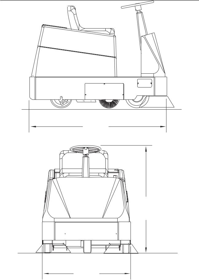
MACHINE DIMENSIONS
56.6" 143.5 cm
47.0" 119.4 cm
36.4"
92.4 cm |
C0459 |
|
American-Lincoln Technology |
1-3 |
114 RS Operator’s Manual |
|

MACHINE SPECIFICATIONS
|
GENERAL MACHINE SPECIFICATIONS |
SWEEPING PATH |
|
Width |
45.0 inches 114.3 cm. Including side brooms |
TRAVEL SPEED |
|
Forward |
4.0 MPH/4.9 KPH |
Reverse |
2.0 MPH/2.48 KPH |
TURNING RADIUS |
|
Right |
46.0 inches116.8 cm. |
Left |
46.0 inches116.8 cm. |
U-turn Clearance |
68.00 inches 172.7 cm. |
DIMENSIONS |
|
Length |
56.6 inches143.5 cm. |
Width |
36.4 inches 92.4 cm. |
Height |
47.0 inches119.4 cm. |
WEIGHT |
|
Standard Machine |
686 LBS .311 KGS (Without Batteries) |
With 228 A.H. Batteries |
1071 LBS.486 KGS |
With 330 A.H. Batteries |
1221 LBS.554 KGS |
TIRES |
|
Type |
Gray Non-Marking |
Rear |
3.0" wide x 10.0"dia. (7.6cm x 25.4cm) Foam Filled |
Front |
2.75" wide x 10.0" dia. (7.0 cm x 25.4 cm) Solid |
BATTERIES |
|
Two 36 VDC Battery Package Options |
|
228 A.H. |
Qty. 3 - 12 VDC Lead Acid Batteries Total Wt. 384 lb/175 kg |
330 A.H. |
Qty. 6 - 6 VDC Lead Acid Batteries Total Wt. 535 lb/243 kg |
DRIVES |
|
Main Broom |
(1) 0.50 HP 36 VDC Electric Motor (372 W.) |
Side Brooms |
(2) 0.13 HP 36 VDC Electric Motor (96.8 W.) |
BRAKING |
|
For Operation |
Dynamic braking to front wheel, using foot pedal. |
For Storage or Service |
Hand operated control to engage two rear wheel lock pins. |
STEERING |
|
System Type |
Single front wheel with chain and sprocket column |
Steering Wheel Diameter |
13 inches (33.02 cm) |
Steering Angle of Front Wheel |
180 degrees Available |
LUBRICATION |
|
Rear Wheels |
Grease Fittings Provided |
Steering Gear |
Grease Fittings Provided |
WHEEL DRIVE SYSTEM |
|
Type |
Front Wheel, Reversible Electric Coaxial Gear Motor |
Rating |
36 VDC .70 HP (500 W.) |
|
|
1-4 |
American-Lincoln Technology |
|
114 RS Operator’s Manual |

MACHINE SPECIFICATIONS
SWEEPING SYSTEM SPECIFICATIONS
MAIN BROOM
Broom bristle mounted in a polycore tube with helical pattern bristle tufted in six double rows.
Length |
27.00 inches (68.6 cm) |
Broom Size |
11.00 inches (27.9 cm) Dia. |
Broom bristle Length |
3.00 inches (7.6 cm) long. (Usable to 1 Inch Length) |
SIDE BROOMS
Polypropylene bristles mounted in a 1.25-inch (3.17-cm) thick marine grade varnished hardwood plate.
Broom Size |
16 inches (40.6 cm) Dia. |
HOPPER |
|
Equipped with dolly wheels and handle. |
|
Volumetric Capacity |
3.0 cubic feet (85.0 lt) |
Weight Capacity |
375 lbs. (170 kg). |
FILTRATION
One pleated treated paper type panel air filter.
Filtering area |
40 square feet (3.7 m2) |
VACUUM FAN |
|
Electric motor is driving a radial impeller. |
|
Motor |
36VDC .62 HP (462W) |
Impeller |
9 inches (22.9 cm) Diameter |
CONTROLS AND INSTRUMENTS
-Side Broom “Off” Switch -Vac Fan “Off” Switch -Push Button Filter Shaker -Push Button Horn
-Control Handle for Main Broom Lift and Sweeping Settings. (Also turns off main broom, side brooms and vacuum impeller)
-Control Handle for Side Broom Lift -Key Start Switch
-Single Pedal Control for Forward/Reverse Motion, Rate of Travel and Braking. -Hour Meter
-Battery Condition Meter
OPTIONAL EQUIPMENT
-Strobe Light
-Back-up Alarm
-Low Battery Shutdown
-Emergency Stop
-Smart Battery Charger Option
-Head, Tail Lights
-Over Head Guard
MAIN BROOM OPTIONS
-Nylon low density -Nylon high density -Proex
American-Lincoln Technology |
1-5 |
114 RS Operator’s Manual |
|
STANDARD HARDWARE & TORQUE VALUES
|
|
SAE - Grade 5 |
|
|
|
|
|
|
|
|
|
|
SAE - Grade 8 |
|
|||||
|
|
|
|
|
|
|
|
|
|
|
|
|
|||||||
|
|
|
|
|
|
|
|
|
|
|
|
|
|
|
|
|
|
|
|
|
Screw |
Grade |
|
Grade |
|
|
|
410H |
|
Brass |
|
Type |
Type |
||||||
|
|
|
|
|
|
|
F & T |
||||||||||||
|
Size |
|
5 |
|
8 |
|
|
|
Stainless |
|
|
B, AB |
|||||||
|
|
|
|
|
|
|
|
& BT |
|||||||||||
|
|
Plated |
|
Plated |
|
|
|
|
|
|
|
|
|
|
|||||
|
|
C |
|
F |
|
C |
|
|
F |
C |
|
F |
|
C |
|
F |
|
||
*6 |
14 |
|
15 |
|
- |
|
- |
18 |
|
|
|
20 |
5 |
20 |
|
23 |
21 |
||
*8 |
27 |
|
28 |
|
- |
|
- |
33 |
|
|
|
35 |
9 |
37 |
|
41 |
34 |
||
*10 |
39 |
|
43 |
|
- |
|
- |
47 |
|
|
|
54 |
13 |
49 |
|
64 |
49 |
||
*1/4 |
86 |
|
108 |
|
130 |
|
151 |
114 |
|
|
|
132 |
32 |
120 |
|
156 |
120 |
||
5/16 |
15 |
|
17 |
|
22 |
|
24 |
19 |
|
|
|
22 |
6 |
- |
|
- |
- |
||
3/8 |
28 |
|
31 |
|
40 |
|
44 |
34 |
|
|
|
39 |
10 |
- |
|
- |
- |
||
7/16 |
44 |
|
49 |
|
63 |
|
70 |
55 |
|
|
|
62 |
16 |
- |
|
- |
- |
||
1/2 |
68 |
|
76 |
|
95 |
|
108 |
85 |
|
|
|
95 |
- |
- |
|
- |
- |
||
9/16 |
98 |
|
110 |
|
138 |
|
155 |
- |
|
|
|
- |
- |
- |
|
- |
- |
||
5/8 |
135 |
|
153 |
|
191 |
|
216 |
- |
|
|
|
- |
- |
- |
|
- |
- |
||
3/4 |
239 |
|
267 |
|
338 |
|
378 |
- |
|
|
|
- |
- |
- |
|
- |
- |
||
7/8 |
387 |
|
- |
|
545 |
|
- |
- |
|
|
|
- |
- |
- |
|
- |
- |
||
1 |
579 |
|
- |
|
818 |
|
- |
- |
|
|
|
- |
- |
- |
|
- |
- |
||
|
|
|
|
|
|
|
|
|
|
|
|
|
|
|
|
|
|
|
|
C = Coarse Thread F = Fine Thread
* = Torque values for #6 through 1/4 are lb./in. All others are lb./ft.
NOTE
Decrease the torque by 20% when using thread lubricant
The torque tolerance is ± on torque values.
C2000/9905
1-6 |
American-Lincoln Technology |
|
114 RS Operator’s Manual |

|
|
|
DECIMAL METRIC CONVERSION TABLE |
||
FRACTION |
DECIMAL |
MILLIMETER |
FRACTION |
DECIMAL |
MILLIMETER |
C-2001/9907 |
|
|
|
|
|
American-Lincoln Technology |
1-7 |
114 RS Operator’s Manual |
|

SAFETY PRECAUTIONS
THE FOLLOWING STATEMENTS ARE USED THROUGHOUT THIS MANUALAS INDICATED IN THEIR DESCRIPTIONS:
 DANGER
To warn of immediate hazards which will result in severe personal injury or death.
 WARNING
To warn of hazards or unsafe practices which could result in severe personal injury or death.
 CAUTION
To warn of hazards or unsafe practices which could result in minor personal injury.
ATTENTION
To warn of unsafe practices which could result in extensive equipment damage.
NOTE
To give important information or to warn of unsafe practices which could result in equipment damage.
THE FOLLOWING INFORMATION SIGNALS POTENTIALLY DANGEROUS CONDITIONS TO THE OPERATOR OR EQUIPMENT. READ THIS MANUAL CAREFULLY. KNOW WHEN THESE CONDITIONS CAN EXIST. THEN, TAKE NECESSARY STEPS TO TRAIN MACHINE OPERATING PERSONNEL.
FOR THE SAFE OPERATION OF THIS MACHINE, READ AND UNDERSTAND ALL WARNINGS, CAUTIONS, AND NOTES.
 WARNING
Machines can ignite flammable materials and vapors. Do not use with or near flammables such as: gasoline, grain dust, solvents, and thinners.
 WARNING
Heavy machinery. Improper use can cause personal injury.
 WARNING
Operate only when lids, doors, and access panels are securely closed.
 WARNING
Use care when reversing machine in confined area.
 WARNING
When servicing the machine, disconnect the batteries first to prevent possible injury.
 WARNING
When working on the machine, empty hopper, remove batteries, clear area of people and obstructions, and use additional people and proper procedures when lifting the machine.
 WARNING
Always empty the Hopper and Disconnect Battery before doing maintenance.
 WARNING
You must have training in the operation of this machine before using it. READ THE INSTRUCTION BOOK.
 WARNING
Do not operate this machine unless it is completely assembled.
 WARNING
Do not use this machine as a step or furniture.
1-8 |
American-Lincoln Technology |
|
114 RS Operator’s Manual |

SAFETY PRECAUTIONS
 WARNING
Be careful when operating the machine on a ramp or incline. Always move slowly on a ramp. Do not turn this machine on a ramp. Do not stop and leave this machine on a ramp.
 WARNING
Stop and leave this machine on a level surface. When you stop the machine, put the power switch in the “OFF” position and engage the Wheel Lock.
 WARNING
To prevent injury, and damage to the machine, do not lift the machine or move it to an edge of a stair or loading dock.
 WARNING
Lead acid batteries generate gases, which can cause an explosion. Keep sparks and flames away from batteries. NO SMOKING. Charge batteries only in area with good ventilation.
 WARNING
Always wear eye protection and protective clothing when working near batteries. Remove all jewelry. Do not put tools or other metal objects across the battery terminals, or the tops of batteries.
 WARNING
Maintenance and repairs must be done by authorized personnel only. Tighten all fasteners. Keep adjustments according to the specifications given in the service manual for the machine. Keep the electrical parts of the machine dry. For storage, keep the machine in a building.
 WARNING
Make sure that all labels, decals, warnings, cautions and instructions are fastened to the machine. Get new labels and decals from Clarke/American-Lincoln.
American-Lincoln Technology |
1-9 |
114 RS Operator’s Manual |
|
MACHINE PREPARATION
C0458 |
FIGURE 1 |
YOUR 114 RS BATTERY MACHINE HAS BEEN SHIPPED COMPLETE, BUT DO NOT ATTEMPT TO OPERATE WITHOUT READING THE FOLLOWING INSTRUCTIONS.
Uncrate the machine and remove all packing material. Inspect the machine for possible shipping damage. Install brooms, as outlined in the Service Instructions Section of this manual. Install batteries as follows (if not included):
1.Turn the key to the “OFF” position.
2.Unplug the polarized connector located next to the operator’s seat.
3.Lift the battery compartment cover and engage the safety latch.
4.Use a battery-lifting device with a 150 lb. (68 KG) capacity to place the batteries in the battery compartment.
5.Install Battery Cables. (See Page 45 for detailed connection information)
6.Charge batteries (See battery charging procedure in the Service Instructions Section of this Manual)
7.Disengage battery cover safety latch and carefully lower cover.
8.Plug the polarized connector into the receptacle located next to the operator’s seat.
9.READ THIS MANUAL before Attempting to Operate the Sweeper.
 WARNING
Hydrogen gas is formed during the charging operation and is explosive! Only charge batteries in a well-venti- lated area with the lid open. Avoid any open flame or electrical sparks. Pulling out the charger plug with the timer on will cause an arc and must be avoided.
1-10 |
American-Lincoln Technology |
|
114 RS Operator’s Manual |
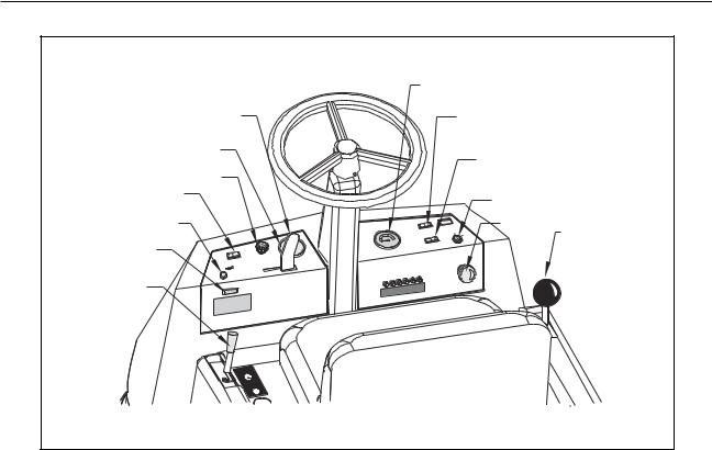
MACHINE CONTROLS
SIDE BROOMS LEVER
HOUR METER
LIGHT SWITCH
FILTER SHAKER SWITCH
HORN |
|
|
|
|
LOW BATTERY LIGHT |
FILTER |
|
ON |
|
|
|
SHAKER |
||
|
HORN |
|
|
DOWN |
|
|
|
|
|
WHEEL LOCK |
|
|
|
|
|
VOLTAG |
E LOW |
||
|
BROOMS |
ARE OFF |
||
|
|
ERIES |
||
|
RECHAR |
GE BATT |
|
|
SIDE BROOMS
UP
WHEELLOCK
UNLOCK
LOCK
BATTERY CONDITION METER
|
|
DUST |
CONTROL |
BATTERY |
ON |
||
OFF |
|
||
|
N |
|
|
CONDITIO |
|
|
|
|
|
|
OFF |
|
|
SIDEBROOMS |
|
|
|
|
ON |
|
|
|
OFF |
|
|
ING |
|
CHECK |
WHILE |
OPERAT |
|
|
|
|
|
DUST CONTROL SWITCH
SIDE BROOMS SWITCH
|
KEY SWITCH |
|
EMERGENCY STOP BUTTON |
ON |
MAIN BROOM LEVER |
CB1 CB5 |
CB4 CB7 |
CB8 |
|
|
C0461 |
FIGURE 2 |
KEY SWITCH - See Figure 2
The Key Switch turned to the right, the “ON” position, will provide power to all Sweeper systems.
HORN BUTTON - See Figure 2
The horn button is active only when the key switch is “on”. Push the horn button to sound the horn.
HOUR METER - See Figure 2
The hour meter is activated when the key switch is in the “On” position. The meter indicates the time, in Hours that the machine has been operated. This is useful for determining service intervals.
LIGHT SWITCH - See Figure 2
The Light Switch is a push-pull type switch that turns on the Front and Rear Lights. Pull the switch “out” to turn on the Lights. Push the switch “in” to turn off the Lights. The Lights are not controlled by the key switch and can be turned on regardless of the key switch position.
SEAT ADJUSTMENT
This lever is located on the right of the seat. This lever allows the seat to be adjusted forward or back when the lever is moved.
FILTER SHAKER SWITCH - See Figure 2
The filter shaker switch is a momentary on rocker type switch that when depressed and held shakes accumulated debris from the dust control filter. Press and hold the switch for 15 seconds to clear the filter. The filter should be cleared periodically while sweeping and prior to emptying the hopper.
SIDE BROOMS LIFT LEVER - See Figure 2
The Side Brooms Lift Lever is a two-position control that allows for Lifting or Lowering of the Side Brooms. Placing the lever to the left lowers the Side Brooms. Placing the lever to the right into the indent raises the Brooms.
American-Lincoln Technology |
1-11 |
114 RS Operator’s Manual |
|
MACHINE CONTROLS
NEUTRAL
NEUTRAL
FORWARD
REVERSE
P4066 |
FIGURE 3 |
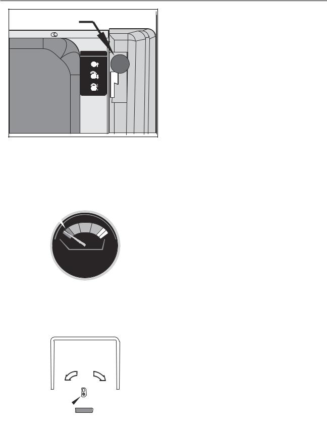
FOOT PEDAL-See Figure 3
The accelerator and directional control foot pedal is located on the floor of the operator’s area. The accelerator and directional control pedal controls the machine direction, travel speed and dynamic braking. If the machine stops due to an electrical system overload in the power panel controller, allow the pedal to return to the neutral position. Reset is automatic when the controller cools.
For Forward Travel - Foot pressure on the upper portion of the pedal will cause the Sweeper to move forward. Increase the foot pressure on the upper portion of the pedal to increase the forward speed.
For Reverse Travel - Put foot pressure on the lower portion of the pedal. The machine will move in reverse. Increase the foot pressure on the lower portion of the pedal to increase the reverse speed.
To Stop the Sweeper - Allow directional control pedal to return to neutral (center position). Pedal will automatically return to centered position, which will automatically provide dynamic braking to stop. If Increased Braking action is desired put light foot pressure to the pedal in the opposite direction of travel until the sweeper stops then allow the pedal to return to center.
|
|
|
|
|
WHEEL LOCK - See Figure 4 |
|
|
|
|
|
|
The Wheel Lock is used to prevent unexpected movement |
|
|
VOLTAGE |
LOW |
of the machine while it is “Parked” for Storage purposes or |
|||
|
|
OFF |
being serviced, such as emptying the hopper. The Wheel |
|||
|
BROOMS |
ARE |
||||
|
|
|||||
|
BATTERIES |
|||||
|
RECHARGE |
|
|
|
Lock is not to be used as a “Brake.” To engage the wheel |
|
|
|
|
|
|
||
|
|
|
|
|
lock, Stop the Sweeper, move the lever out of the indent, |
|
|
|
|
|
|
and push it forward. The wheel lock will engage with the |
|
|
|
|
|
|
lever in the forward position. |
|
|
|
|
|
|
WARNING |
|
|
|
|
|
|
The Wheel Lock is not to be used as a “Brake.” Make |
|
|
|
|
|
|
sure the sweeper has come to a complete stop before |
|
|
|
|
|
CK |
engaging the wheel lock. Personal Injury or Property |
|
|
|
|
|
ELLO |
|
|
|
|
|
HE |
Damage Can Result From Using the Wheel Lock as a |
||
|
|
|
W |
|
||
|
|
|
|
LOCK |
||
|
|
|
|
|
“Brake.” |
|
|
|
|
|
UNLOCK |
|
|
|
|
|
|
|
WARNING |
|
C0466 |
FIGURE 4 |
Turn the Key Switch “Off” and engage the Wheel Lock |
||||
before Leaving the Operator’s Compartment. Do Not |
||||||
|
|
|
|
|
||
|
|
|
|
|
Leave the Sweeper Unattended. |
|
1-12 |
|
|
|
|
American-Lincoln Technology |
|
|
|
|
|
|
114 RS Operator’s Manual |
|
MACHINE CONTROLS
|
MAIN BROOM |
|
LIFT LEVER |
|
MAIN BROOM |
|
OFF |
|
SWEEP |
|
FLOAT |
C0467 |
FIGURE 5 |
|
CHARGE BATTERIES |
WHEN NEEDLE STAYS IN RED ZONE |
|
||
WHILE SWEEPER IS BEING OPERATED |
|||
|
|
|
|
BATTERY |
- |
+ |
|
CONDITION |
|||
|
|
||
|
|
|
|
C0468 |
FIGURE6 |
MAIN BROOM LIFT LEVER - See Figure 5
The main broom lift lever is located on the right side next to the driver’s seat. To lower the main broom, grasp the lever, move it to the left to clear the locking notch and pull back to the first or second notch. The first notch is the “Sweep” position, which is used for normal sweeping conditions, and will result in longer broom life. The second notch is the “Float” position and is used when sweeping very uneven surfaces. The main broom, side brooms and vacuum fan will start when the lever is moved from the “Off” position.
SIDE BROOMS SWITCH - See Figure 2
The Side Brooms Switch is a two-position rocker type On/ Off Switch. Depress the right side of the switch to turn the side brooms on.
Depress the left side of the switch to turn the side brooms off. The side brooms will rotate when the Main Broom Lever is placed in the Sweep or Float Position.
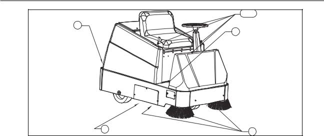
BATTERY CONDITION METER - See Figure 6
The meter shows the condition of the battery, while the machine is running, under load. Batteries are charged when indicator is in the green zone. When indicator stays in the red zone, batteries must be charged.
LOW BATTERY LIGHT (OPTION) - See Figure 2
The Low Battery Shutdown prevents excessive discharging of the batteries. When the batteries get low the indicator light comes on and the Brooms turn off. When the indicator light, illuminates Charge the batteries.
DUST CONTROL SWITCH - See Figure 2
The dust control switch is a two-position rocker switch located on the right instrument panel and is used to control operation of the vacuum fan for the dust control system. To turn on the vacuum fan, push the right side of the rocker switch. To turn off the vacuum fan push the left side of the rocker switch. The vacuum fan will only operate when the main broom lever is moved out of the “Off” position.
|
UNLOCK |
LOCK |
LOCK |
|
HOPPER |
C0469 |
LATCH |
FIGURE 7 |
HOPPER RELEASE LATCH - See Figure 7
The Hopper Release Latch is located on the Hopper at the rear of the sweeper. To disengage the latch, turn the handle to the left to the nine O’clock positions. The Hopper is now ready to be removed. To engage the Hopper latch, ensure the hopper is properly seated and turn the handle to the right to the three O’clock position. You will feel the latch engage if the hopper is properly seated.
EMERGENCY STOP BUTTON (OPTION) - See Figure 2
The emergency stop button is a Red Mushroom switch, which is located near the key switch. To quickly shut down power to the machine, push the large red button. To reset the shut down button; first turn the red button clockwise in the direction of the arrows marked on the switch. Now turn the key switch to the “Off” position then clockwise to the “start” position, when you release the key switch and allow it to return to the “On” position the Sweeper will operate.
American-Lincoln Technology |
1-13 |
114 RS Operator’s Manual |
|
OPERATING INSTRUCTIONS
1,2
6
3
114 |
RS |
|
|
4 |
5 |
|
|
|
C0470 |
|
FIGURE 8 |
NOTE
Before starting, perform the pre-start checks.
PRE-START CHECKLIST - See Figure 8
1.Check controls for proper operation
2.Make sure all controls are in the “Off” position
3.Be sure accelerator / directional control pedal is in the neutral position.
4.Check all Dust flaps for damage or wear.
5.Check Main Broom and Side Broom for proper broom pattern.
6.Ensure that the hopper latch is properly engaged.
TO START MACHINE
1.Release the Wheel Lock.
2.Turn key to “On” position.
POST START CHECKLIST
1.Check the Battery Condition Meter for sufficient battery charge. This must be done with the machine running.
TO TRANSPORT MACHINE
1.Be sure the Main Broom and Side Broom Controls are in the “UP” or “OFF” position with all other controls in the “OFF” position.
2.Push forward on the directional control pedal to place the machine in motion.
3.Vary your foot pressure on the directional control pedal to obtain desired travel speed.
4.To stop, allow directional control pedal to return to neutral (centered) position. (Pedal will automatically return to neutral when foot pressure is released).
TO BEGIN SWEEPING
1.Lower the Side Brooms by Moving the Side Broom Lift Lever to the “Down” Position.
2.Turn on the Side Brooms by setting the side brooms switch to the “On” Position.
3.Turn on the Dust control system by setting the Dust Control Switch to the “On” position.
4.Move the broom lift lever to the “Sweep” or “Float” position.
5.Vary your foot pressure on the directional control pedal to obtain desired travel speed.
6.To stop, allow directional control pedal to return to neutral (centered) position. (Pedal will automatically return to neutral when foot pressure is released).
1-14 |
American-Lincoln Technology |
|
114 RS Operator’s Manual |
OPERATING INSTRUCTIONS
|
SIDE AISLES |
|
MAIN AISLE |
P4134/0001 |
SIDE AISLES |
P4134 |
FIGURE 9 |
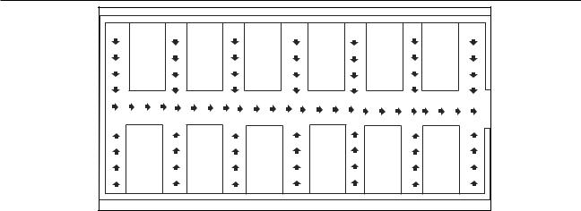
HELPFUL HINTS FOR SWEEPING - See Figure 9
Here are some suggestions to keep in mind while sweeping.
1.Plan your sweeping in advance. Try to arrange long runs with minimum stopping and starting.
2.Pick up large debris before sweeping with the Machine.
3.Use the sweeper to sweep debris from side aisles into the main aisle.
4.After the Sweeper has made a sweeping run, turn off the dust control switch and use the filter shaker, Push and hold the shaker switch for approximately 15 seconds
5.Allow a few inches of overlap of sweep paths. This will eliminate leaving dirty patches.
6.Sweep in straight paths and do not bump posts or scrape the sides of the machine.
7.Periodically turn the sweeping broom end for end to prevent the bristles from “setting” in one direction.
8.Do not turn steering wheel too sharply when machine is in motion. The machine is very responsive to movement of the steering wheel - so avoid sudden turns.
9.As the Hopper becomes full, the sweeper will start to leave debris on the floor. When this occurs stop sweeping and empty the hopper.
TO EMPTY THE HOPPER
1.Place the Main Broom Lever in the “Off” position, raise Side Brooms, and proceed to the disposal site for emptying the Hopper.
2.Stop the Sweeper, Turn off the dust control switch and shake the filter for 15 seconds.
3.Place all controls in the “Off ” position and engage the wheel Lock.
4.Proceed to the rear of the Sweeper and unlock the Hopper latch.
5.Grasp the Hopper Handle and remove the hopper.
6.Dump the Hopper. Get Help if needed.
7.Position the Hopper and install it making sure that the Hopper goes in squarely.
8.Lock the Hopper Latch.
9.Resume Sweeping or perform the Post Operation Checklist if finished Sweeping.
TO STOP THE SWEEPING OPERATION
When the sweeping has been completed follow these instructions.
NOTE
After stopping, perform these post operation checks.
POST OPERATION CHECKLIST
1.Before turning off key switch, Check Battery Condition Meter.
2.Stop Machine and turn key switch to “Off” and Engage Wheel Lock.
3.Check all flaps for wear, damage, and adjustment.
4.Empty Hopper
5.Check Main Broom and Side Broom for wear or damage.
6.Charge Batteries if determined to be necessary in step 1 above.
American-Lincoln Technology |
1-15 |
114 RS Operator’s Manual |
|
SERVICE CHART
|
|
|
5 |
8 |
|
|
|
|
|
|
7 |
2 |
|
ROL |
|
BATTERY |
DUSTCONT |
|
|
OFF |
|
||
CONDITION |
OFF |
||
|
SIDEBROOMS |
||
|
|
OFF |
|
R SHAKER |
TING |
|
|
FILTE ON |
ILEOPERA |
|
|
|
CHECKWH |
|
|
MS |
|
|
|
SIDE BROO |
UP |
|
|
HORN |
|
|
|
DOWN |
|
|
|
|
CB1 CB5 CB4 |
CB7 CB8 |
|
|
|
|
|
VOLTAGE LOWFF |
|
|
|
BROOMS ARE ORIES |
|
|
|
RECHARGE BATTE |
|
|
|
|
|
|
12 |
7 |
|
|
|
4 |
|
|
|
9 |
|
|
|
3,10 |
|
|
13 |
|
|
|
|
1 |
|
|
|
7 |
|
|
|
6,11 |
|
|
C0474 |
|
|
|
|
C0474 |
FIGURE 10 |
||
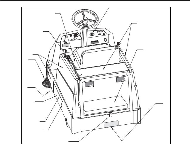
SERVICE CHART FOR 114 RS
Check items for proper operation. If service is required, please consult your Clarke/American-Lincoln Authorized Distributor:
EVERY 8 HOURS or DAILY
1.All flaps for wear or damage.
2.Wheel Lock for proper operation.
3.Main Brooms for wear or damage.
4.Side Brooms for wear or damage.
5.Check Batteries and charge if necessary. (See Page 22 for Battery charging instructions)
6.Empty Hopper and ensure latch is properly secured.
7.All Hardware, Panels and Covers for tightness and security
50 HOUR MAINTENANCE CHECKLIST
8.Check battery electrolyte level.
9.Lubricate front wheel bearing and pivot.
10.Rotate Main Broom end for end to prevent uneven wear.
100 HOUR MAINTENANCE CHECKLIST
11.Clean Hopper.
12.Remove and Clean / Inspect Dust Control Filter. Replace if necessary
13.Lubricate Wheel lock pins.
1-16 |
American-Lincoln Technology |
|
114 RS Operator’s Manual |

SERVICE CHART
For service assistance, consult your local Clarke/American-Lincoln Distributor. For best performance, replace worn parts with genuine Clarke/American-Lincoln parts.
Refer all Maintenance and Service Requirements to Qualified Maintenance Personnel.
Do not attempt to Service this Machine until you have read and understand all Safety Warnings associated with the equipment you are working with.
 WARNING
Electrical repairs must be done by authorized personnel only. Consult your Clarke Authorized Service Person to do service procedures. Use only genuine Clarke/American-Lincoln parts.
 WARNING
Always park on a level surface, turn key off, and engage wheel lock before working on the machine to keep it from creeping or rolling.
IMPORTANT
If towing or pushing is required, disconnect motor lead located on the terminal block on the bottom of the machine
 WARNING
Maintenance and repairs must be done by authorized personnel only. Always empty the Hopper and disconnect the batteries before doing any maintenance. Keep all fasteners tight. Keep adjustments according to the specifications as shown in the Service Manual for this machine.
 WARNING
Always wear eye protection and protective clothing when working near batteries. Do not put tools or other metal objects across the tops of the batteries. NO SMOKING.
 WARNING
To prevent damage to the machine and discharge across the tops of the batteries, do not fill the batteries above the bottom of the tube in each cell. Wipe any acid from the machine or the tops of the batteries. Do not add acid to a battery after installation.
 WARNING
Always engage the safety latch before working under the Battery cover.
 WARNING
Turn Key Off Before removing Battery Connector. Disconnecting the Battery with the key switch on will produce sparks and Could cause an Explosion.
American-Lincoln Technology |
1-17 |
114 RS Operator’s Manual |
|
SERVICE INSTRUCTIONS
2
4
1
3
C0477a |
FIGURE 11 |
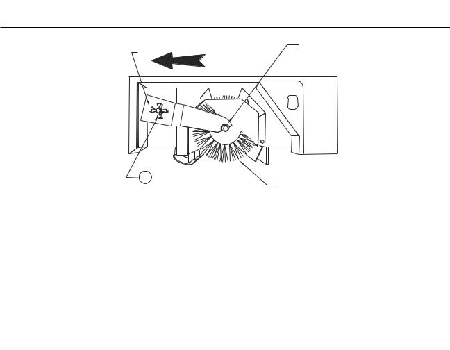
MAIN BROOM SERVICE INSTRUCTIONS
TO CHECK THE MAIN BROOM SWEEP PATTERN
Check the main broom sweep pattern after changing the broom or when poor sweeping performance is encountered while sweeping.
1.While the machine is not moving, lower the main broom to the SWEEP position and let machine sweep in one spot for a short period.
2.Before moving machine, move main broom lever to the OFF position and move the sweeper forward until you can see the pattern left by the main broom bristles on the floor.
3.Check the width of the pattern on the floor to determine if the main broom requires adjustment.
-A normal sweep pattern left on the floor will be between one and two inches wide.
-A pattern that is more than two inches wide indicates the broom linkage needs to be adjusted “UP.”
-A pattern that is less than one inch wide indicates the broom linkage needs to be adjusted “DOWN.”
 WARNING
Always engage the safety latch before working under the Battery cover.
TO ADJUST THE MAIN BROOM SWEEP HEIGHT
When changing the sweep height adjustment it is recommended that the bolt be adjusted one turn at a time, After adjustment, recheck the sweep pattern to determine if further adjustment is necessary.
1.Gain access to the main broom height adjustment bolt by lifting the battery compartment cover, locking it in the up position and removing the right side panel cover.
2.Locate the Main Broom Height Adjustment bolt, which is located at the bottom of the Main Broom Lift linkage.(It will have a spring around it)
3.Turn the adjustment screw as described below.
-Turn the adjustment bolt counterclockwise to INCREASE the sweep pattern width. -Turn the adjustment screw clockwise to DECREASE the sweep pattern width.
 WARNING
Always park on a level surface, turn key off, and engage wheel lock before working on the machine to keep it from creeping or rolling.
TO CHANGE THE MAIN BROOM [See Figure 11]
Replace the main broom when the bristles become worn to 1-inch length.
1.Park the sweeper on a smooth level surface and engage the wheel lock.
2.Gain access to the main broom by opening the left-hand side broom compartment door.
3.Remove the Main broom Idler hub [Item 2] by loosening the threaded knob [Item 1].
4.Grasp the Main Broom [Item 3] and remove it from the drive hub. [Item 2].
5.Insert Replacement Broom [Item 3] Into the broom compartment. Pay special attention to the slots on the broom, it may be necessary to rotate the broom so the tabs on the drive hub align with the slots on the broom.
6.Reinstall the idler hub [Item 2] to the broom and over the locator stud [Item 4] and screw provided for the threaded knob [Item 1].
7.Install the threaded knob and close the Broom Door.
8.Recheck Main Broom Sweep Pattern.
1-18 |
American-Lincoln Technology |
|
114 RS Operator’s Manual |
SERVICE INSTRUCTIONS
|
FLOOR |
FLOOR |
|
CONTACT |
|
|
CONTACT |
|
|
AREA |
|
|
AREA |
|
|
|
|
C0472 |
|
FIGURE 12 |
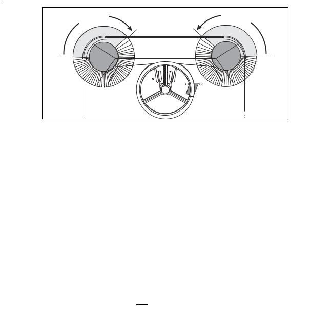
SIDE BROOMS SERVICE INSTRUCTIONS
The Side Brooms Sweeping angle is not adjustable however the height of the side brooms can be adjusted to compensate for wear as the brooms become worn from use. Two access panels need to be removed to make the Side Broom Height adjustment.
TO CHECK THE SIDE BROOM SWEEP PATTERN
1.Park the machine on a smooth level surface and turn the Side Broom Switch to the “ON” position.
2.Place the Side Broom Lift Lever in the “DOWN” position.
3.Move the Main Broom Lever to the “SWEEP” position.
4.While staying in place, allow the side brooms to sweep for a short period. (Allow enough time for the side brooms to leave a clean footprint on the floor).
5.Place the Side Broom Lift Lever in the “UP” position.
6.Turn the Side Broom Switch to the “OFF” position.
7.Move the Main Broom Lever to the “OFF” Position.
8.Back the sweeper away from the area where the Pattern was left.
9.Turn Key Switch to the “OFF” position and engage Wheel Lock.
10.Leave operator’s compartment and check the Pattern to determine the Floor Contact area.
11.Determine if adjustment to the side brooms height is necessary by comparing the floor contact area to the diagram in figure 12.
 WARNING
Always park on a level surface, turn key off, and engage wheel lock before working on the machine to keep it from creeping or rolling.
TO CHANGE THE SIDE BROOMS HEIGHT ADJUSTMENT
1.Park Machine on a smooth level surface, turnkey switch to “OFF” Position and engage Wheel Lock.
2.Place the Side Brooms Lift Lever in the “DOWN” Position.
3.Remove the two access panel screws and remove panel.
4.Loosen the four bolts that pass through the slots in the side broom motor lift bracket.
5.Lower the side broom motor in the slots so the broom contacts the floor as shown. (See figure 12)
6.Tighten the four bolts and recheck the sweep pattern.
7.Reinstall the access panels when proper adjustment has been achieved.
TO CHANGE THE SIDE BROOMS (See Page 47 for detailed assembly)
Change the side brooms when the bristles become worn to less than 3 inches length.
1.Park Machine on a smooth level surface, turnkey switch to “OFF” Position and engage Wheel Lock.
2.Place the side brooms lever in the “DOWN” Position.
3.Remove the three (3) ¼ inch bolts and nuts that hold the broom to the motor flange.
4.Install the replacement Broom and fasten using the hardware removed in step 3.
American-Lincoln Technology |
1-19 |
114 RS Operator’s Manual |
|
SERVICE INSTRUCTIONS
DUST CONTROL SYSTEM SERVICE INSTRUCTIONS
The Dust Control system consists of a Filter Baffle and a Panel Filter. The filter baffle is located under the dust control filter and should be checked/cleaned when the hopper is being emptied. The Panel Filter is located in the rear compartment behind the seat.
 WARNING
Always park on a level surface, turn key off, and engage wheel lock before working on the machine to keep it from creeping or rolling.
TO CLEAN THE FILTER BAFFLE
The filter baffle should be cleaned as a first step when the dust control system fails to effectively control dusting while sweeping.
1.Park the sweeper on a smooth level surface, Turn the key switch to the “OFF” position and engage the wheel lock.
2.Disconnect the Battery Connector, which is located next to the seat.
3.Remove the hopper.
4.Lower the baffle and inspect for debris lodged in the baffle passages.
5.Dislodge all debris from the baffle manually or with compressed air not to exceed 100 PSI.
6.Raise the baffle. Making sure the baffle “Locks” into place.
7.Reinstall the hopper.
8.Reconnect the Battery and return the Sweeper to service.
 WARNING
Always engage the safety latch before working under the Battery cover.
 WARNING
Turn Key Off Before removing Battery Connector. Disconnecting the Battery with the key switch on will produce sparks and Could cause an Explosion.
TO CLEAN THE PANEL FILTER
Clean the Panel filter when the shaker fails to adequately clear the filter pleats. (Refer to page 39 for detailed assembly drawing)
1.Park the sweeper on a smooth level surface, Turn the key switch to the “OFF” position, and engage the wheel lock.
2.Disconnect the Battery Connector, which is located next to the seat.
3.Raise the Battery compartment cover and engage the safety latch.
4.Remove the rear cover.
5.Locate and remove the four wing nuts that hold the filter manifold assembly in place over the filter.
6.Disconnect the shaker motor leads and the Vac fan leads and lift the Vac Fan/Manifold assembly off thedust filter.
7.Remove the filter and blow the dust off the filter with compressed air not to exceed 100 PSI
8.Reinstall the cleaned filter and assemble the Vac Fan/Manifold Assembly to the filter.
9.Connect the shaker motor leads and the Vac fan leads.
10.Install the four Wing Nuts and tighten enough to lightly compress the gasket on the filter.
11.Reinstall the Rear cover and lower the Battery Compartment cover.
12.Reconnect the Battery and return the Sweeper to service.
 WARNING
Always engage the safety latch before working under the Battery cover.
 WARNING
Turn Key Off Before removing Battery Connector. Disconnecting the Battery with the key switch “on” will produce sparks and Could cause an Explosion.
 WARNING
Always park on a level surface, turn key off, and engage wheel lock before working on the machine to keep it from creeping or rolling.
TO CHANGE THE PANEL FILTER
Change the filter when obvious damage is evident, Inspect for leakage or a heavily loaded filter to the point that cleaning and shaking of the filter has no effect on clearing the pleats.
1-20 |
American-Lincoln Technology |
|
114 RS Operator’s Manual |
SERVICE INSTRUCTIONS
TO CHANGE THE PANEL FILTER - Cont.
1.Park the sweeper on a smooth level surface, Turn the key switch to the “OFF” position and engage the wheel lock.
2.Disconnect the Battery Connector, which is located next to the seat.
3.Raise the Battery compartment cover and engage the safety latch.
4.Remove the rear cover.
5.Locate and remove the four wing nuts that hold the filter manifold assembly in place over the filter.
6.Disconnect the shaker motor leads and the Vac fan leads and lift the Vac Fan/Manifold assembly off thedust filter.
7.Remove and replace the dust filter.
8.Reinstall the cleaned filter and assemble the Vac Fan/Manifold Assembly to the filter.
9.Connect the shaker motor leads and the Vac fan leads.
10.Install the four Wing Nuts and tighten enough to lightly compress the gasket on the filter.
11.Reinstall the Rear cover and lower the Battery Compartment cover.
12.Reconnect the Battery and return the Sweeper to service.
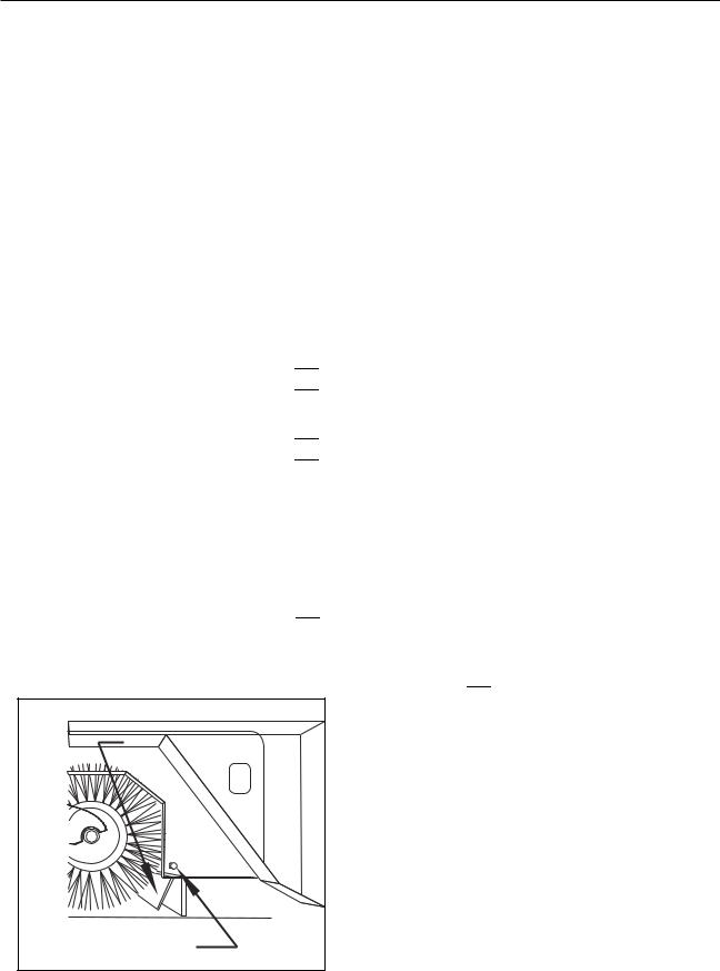
FLAP SERVICE INSTRUCTIONS
The Flaps are very important to the sweeping process. Inspect the Flaps Daily and replace any flap that shows signs of wear or deterioration. The drive wheel and side flaps are adjustable and should be adjusted so there is a recommended 1/16" to 1/8" gap between the floor and the bottom edge of the flaps. The adjustable flaps have slotted mounting holes to facilitate adjustment. The Recycling flap is also an adjustable flap and should be adjusted so the flap touches the broom. The adjustment bolt is located inside the left side broom chamber door. All other flaps require no adjustment and should be replaced when worn or damaged.
 WARNING
Turn Key Off Before removing Battery Connector. Disconnecting the Battery with the key switch on will produce sparks and Could cause an Explosion.
 WARNING
Always park on a level surface, turn key off, and engage wheel lock before working on the machine to keep it from creeping or rolling.
TO ADJUST THE DRIVE WHEEL AND SIDE FLAPS
1.Park Sweeper on a smooth level surface. Turn the key switch to the “OFF” position and engage the wheel lock.
2.Disconnect the Battery Connector located next to the seat.
3.Loosen the Flap retaining screws and adjust the flap to clear the floor and leave a 1/16" to 1/8" Gap.
4.Tighten Flap retaining screws while holding flap in position.
5.Reconnect the Battery Connector.
 WARNING
Turn Key Off Before removing Battery Connector. Disconnecting the Battery with the key switch on will produce sparks and Could cause an Explosion.
|
RECYCLING FLAP |
|
FLAP ADJUSTMENT |
|
SCREW |
C0477b |
FIGURE 13 |
 WARNING
Always park on a level surface, turn key off, and engage wheel lock before working on the machine to keep it from creeping or rolling.
TO ADJUST THE RECYCLING FLAP
1.Park Sweeper on a smooth level surface. Turn the key switch to the “OFF” position and engage the wheel lock.
2.Disconnect the Battery Connector located next to the seat.
3.Open the left side broom door and locate the recycling flap adjustment screw (See Figure 13)
4.Loosen the adjustment screw and turn the flap upwards so the flap touches the ends of the broom bristles.
5.Tighten the adjustment screw while holding the flap in place.
6.Close and Latch the left side broom door Reconnect the Battery.
American-Lincoln Technology |
1-21 |
114 RS Operator’s Manual |
|
SERVICE INSTRUCTIONS
|
SAFETY |
|
LATCH |
C0471 |
FIGURE 14 |
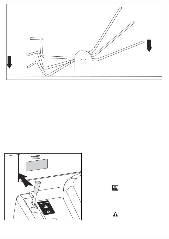
BATTERY SERVICE INSTRUCTIONS
TO CHARGE THE BATTERIES
1.Ensure Wheel Lock is engaged and key switch is “Off”.
 WARNING
Turn Key Off Before removing Battery Connector. Disconnecting the Battery with the key switch on will produce sparks and Could cause an Explosion.
 WARNING
Always wear eye protection and protective clothing when working near Batteries.
 WARNING
Remove all Jewelry and do not lay tools etc. across the tops of Batteries. Batteries produce Explosive Hydrogen Gas. Keep Sparks and Flames away from Batteries. NO SMOKING.
 WARNING
Always engage the safety latch before working under the Battery cover.
2.Disconnect Machine Battery Connector.
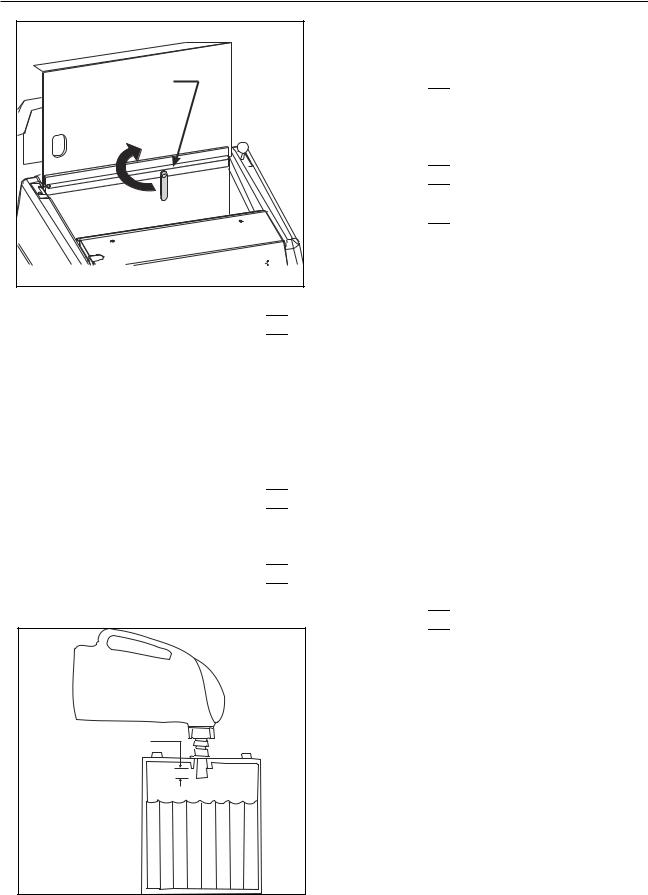
3.Raise Battery Cover and engage Safety Latch. (See Figure 14)
4.Insert charging plug into battery receptacle.
5.Plug power cord into proper AC source.
6.Leave battery cover open while charging.
7.Follow the charging instructions provided on the Charger.
8.Maintain electrolyte level in batteries check after charging. Add distilled water as needed (See Figure15)
 WARNING
Hydrogen gas is formed during the charging operation and is explosive! Only charge batteries in a well-venti- lated area with the lid open. Avoid any open flame or electrical sparks. Pulling out the charger plug with the Charger on will cause an arc and must be avoided.
 WARNING
Batteries are heavy. Use two people to lift the batteries.
DISTILLED WATER
FILL TO 1/4 INCH
FROM BOTTOM OF TUBE
1/4 INCH (6mm)
 WARNING
Always engage the safety latch before working under the Battery cover.
TO REMOVE THE BATTERIES
1.Turn Key Switch “Off” and engage the wheel lock.
2.Unplug the battery connector located next to the operator’s seat.
3.Raise the battery compartment cover and engage the Safety Latch.(See Figure 14)
4.Disconnect the Battery Cables.
5.Lift the Batteries out one at a time.
P4074 |
FIGURE 15 |
1-22 |
American-Lincoln Technology |
|
114 RS Operator’s Manual |
 Loading...