


TE200

M358 E 05.4.NF.1
ECLIPSE TE2000 INVERTED
MICROSCOPE
PERFECT FOCUS SYSTEM
T-PFB Perfect Focus Module
T-PFC Perfect Focus Controller
T-FLC2-E Motorized Cassette Holder
Instructions


Preface
Thank you for purchasing the Nikon products.
This instruction manual is written for the users of the Nikon’s Eclipse TE2000-E Inverted Microscope Perfect Focus
System.
To ensure correct usage, read this manual carefully before operating the instrument.
• It is prohibited to reproduce or transmit this manual in part or whole without Nikon’s expressed permission.
• The contents of this manual are subject to change without notice.
• Although every effort has been made to ensure the accuracy of this manual, if you note any points that are unclear or
incorrect, contact your nearest Nikon representative.
• Some of the products described in this manual may not be included in the set you have purchased.
• Be sure to read the instruction manuals for TE2000-E/U/S Inverted Microscope.
1

Warning for Using this Product
WARNING and CAUTION Symbols
Although Nikon products are designed to provide the utmost safety during use, incorrect usage or failure to follow the
safety instructions provided may cause personal injury or property damage. To ensure correct use, read the instruction
manual carefully and thoroughly before using the instrument. Do not discard the manual; keep it handy for easy
reference.
Safety instructions within this manual are accompanied by the following symbols to highlight their importance. For your
safety, always follow the instructions accompanying these symbols.
Symbol Meaning
WARNING
CAUTION
Disregarding instructions accompanying this symbol may lead to serious injury or death.
Disregarding instructions accompanying this symbol may lead to injury or property
damage.
2

Warning for Using this Product
A
t
1. LED safety
WARNING
This product uses the near-infrared region lights (infrared band) emitted from an infrared LED to perform focus
control. This product has European safety standard EN60825-1: 2001 and International safety standard
IEC60825-1: 2001 approval. And its LED safety class is categorized as Class 1.
Use of controls or adjustments or performance of procedures other than those specified herein may result in
hazardous radiation exposure.
Location of the safety labels on the T-PFB Perfect Focus module
• The safety labels are affixed on the T-PFB Perfect Focus module.
• Under normal conditions, infrared rays are irradiated from the part in the figure below. Be careful.
(1) Caution label (2) Class 1 LED product label (3) Safety standard label
A
T-PFB Perfect Focus module
(For easy understanding, each
perture for the infrared ligh
emission
(1)
part is removed in this picture.)
(2)
View A
(3)
3

Warning for Using this Product
2. Handle the system gently.
3. Do not disassemble.
4. AC adapter of the perfect focus (PF) controller
WARNING
Components of this system are precision optical instruments. Handle them carefully, and do not subject them
to any shocks.
In particular, the precision of the objectives can be adversely affected even by weak shocks.
Disassembly may cause malfunction and / or electric shock, and will lead to the forfeiture of all claims against
warranty. Do not disassemble any part other than those described in this manual. If you experience any
problem with this product, contact your nearest Nikon representative.
The PF controller uses the AC adapter as the power source. Be sure to use the adapter specified in Chapter
IX, “Specification.” Use of other adapter may cause a malfunction, abnormal heating, or serious damage.
• To avoid malfunction or the risk of fire, locate the AC adapter on the well-ventilated place. Do not cover the AC
adapter with any materials, otherwise poor heat radiation may cause overheating of it.
• Before connecting the AC adapter to the PF controller, be sure to turn off the power switch of the PF controller (flip
to the O side) to avoid malfunctions.
5. Power cord for the AC adapter of the PF controller
To prevent electric shock, always turn off the power switch (switch to the O side) of the PF controller before
attaching or detaching the power cord. Use one of the power cords specified in Chapter IX, “Specification.”
Use of an improper power cord can result in fire or other hazard. Also note that the power supply is classified
as subject to the protection class I against electric shock. Therefore, be sure to connect it to a protective earth
terminal.
4

Warning for Using this Product
1. Do not take a look at the radiation light from the LED.
2. Do not wet the instrument.
3. Dirt on the lens
4. Installation location
CAUTION
When this instrument is turned on, weak near-infrared rays (infrared band) are emitted through the objective.
The light intensity is categorized as Class 1 level and is not harmful. But avoid direct viewing.
If the instrument gets wet, a short circuit may cause a malfunction or abnormal heating. If you accidentally spill
a liquid on the instrument, immediately turn off the power switch (flip to the O side) and unplug the power cord
from the wall outlet. Then use a dry cloth to wipe away the moisture. If any liquid gets inside the instrument,
do not use it; instead, contact your nearest Nikon representative.
Scratches, dirt, and fingerprints on the optical parts, such as lenses and filters, will adversely affect the
microscope image. If these parts get dirty, clean them by following the instructions described in Chapter VIII,
“Care and maintenance.”
Using or storing this instrument under unsuitable conditions may damage it or may have an adverse effect on
its accuracy. The following conditions should be kept in mind when selecting the installation location:
• Choose a flat surface with little vibration.
• Choose a location less exposed to hazards in the event of collisions, earthquakes, or other potential disasters. If
required to keep the device from falling, use strong wires or other means to secure this product to the worktable or
to another heavy, stable item.
• Avoid a brightly lit location such as a room that receives direct sunlight.
• Choose a location that is free from dust or dirt.
• Do not install this product in a hot and humid location. (Mold or condensation will form on the lenses and filters.)
• The room light just above the microscope may come into the objective as an extraneous light. (Especially when
using a condenser lens with longer working distance such as SLWD, ELWD and LWD lenses.) To avoid this, Nikon
recommends turning off the room light above the microscope when observing the image.
• Install the equipment in a location where the power cord can be easily unplugged from the AC inlet of the AC
adapter in case of emergency.
5. Focusing knobs
• Never turn the focus knobs on the left and right sides of the microscope in opposite directions at the same time, as
doing so can result in damage to the microscope.
• Turning the coarse focus knob as far as it will go and then attempting to turn it further will result in damage to the
microscope. Never use undue force to turn the knob.
• The coarse focus knob turns in sync with the motorized escape, refocus movements, or calling of the nosepiece
up/down position. To prevent malfunctions, avoid contact with the coarse focus knob during the knob is rotating.
6. Vibrations during motorized operation
This product is designed to minimize vibrations caused by motors inside, however, note that even the
minimized vibration may affect on image observation depending on service condition.
7. Electromagnetic waves
This product emits weak electromagnetic waves. The accuracy of any precision electronic equipment may be
adversely affected if positioned too close. If this product affects TV or radio reception, move the radio or TV
further away from the product.
5

Contents
Preface................................................................................................................................................................................ 1
Warning for Using this Product ........................................................................................................................................... 2
I Overview ...................................................................................................................................................................... 8
1 Overview.............................................................................................................................................................. 8
2 Features............................................................................................................................................................... 8
3 Offset function ........................................................................................................................................................ 8
4 Specimen ............................................................................................................................................................... 9
4.1 Suitable specimen ........................................................................................................................................... 9
4.2 Suitable objectives........................................................................................................................................... 9
4.3 Not-suitable specimen................................................................................................................................... 10
II Name and Function of Each Part ............................................................................................................................... 11
1 Name of Each Part .......................................................................................................................................... 11
2 T-PFC PF Controller............................................................................................................................................. 12
III Preparation................................................................................................................................................................. 14
1 T-RCP Remote Control Pad................................................................................................................................. 14
2 Startup and Shutdown of the Remote Control Pad............................................................................................... 16
3 Registering Data of the Objectives ....................................................................................................................... 17
For deleting the registered data........................................................................................................................... 19
Important: list of objectives requiring data registration......................................................................................... 19
4 Registering Installation Information of Objectives Mounted on Nosepiece........................................................... 19
IV Operating Procedures ................................................................................................................................................ 21
1 Basic Operation.................................................................................................................................................... 21
2 Registering and Restoring the Offset Amount ...................................................................................................... 23
2.1 Registering the Offset Amount....................................................................................................................... 23
2.2 Restoring the Offset Amount ......................................................................................................................... 24
3 Registering and Restoring the Vertical Position of the Nosepiece........................................................................ 24
3.1 Registering the Vertical Position of the Nosepiece........................................................................................ 24
3.2 Escaping the Objective.................................................................................................................................. 25
3.3 Restoring the Vertical Position of the Nosepiece........................................................................................... 25
3.4 About the Movement of the Objective in Registering and Restoring the Vertical Position of the Nosepiece. 26
V Connecting a PC........................................................................................................................................................ 27
Connecting a PC ................................................................................................................................................. 27
Communications cable........................................................................................................................................ 27
Specification for serial interface communication.................................................................................................. 27
Communication commands................................................................................................................................. 27
VI Assembling................................................................................................................................................................. 28
Required tools ..................................................................................................................................................... 28
Block diagram...................................................................................................................................................... 29
1 Checking Components ......................................................................................................................................... 30
2 Mounting the T-FLC2-E Motorized Cassette Holder............................................................................................. 30
3 Mounting the T-PFB PF Module........................................................................................................................... 31
6

Contents
4 Mounting Stage-up Kits ........................................................................................................................................ 31
5 Mounting the Motorized Nosepiece ...................................................................................................................... 31
6 Mounting the Stage .............................................................................................................................................. 32
7 Mounting IR-cut Filters ......................................................................................................................................... 32
8 Connecting Cables ............................................................................................................................................... 33
Rear view of the PF Controller ............................................................................................................................ 33
Cables ................................................................................................................................................................. 33
Checking Connections......................................................................................................................................... 34
VII Troubleshooting ......................................................................................................................................................... 35
1 During System Startup ......................................................................................................................................... 35
2 While Using the Perfect Focus Functions............................................................................................................. 35
VIII Care and Maintenance............................................................................................................................................... 38
1 Lens Cleaning ...................................................................................................................................................... 38
2 Cleaning This Product ...................................................................................................................................... 38
3 Disinfecting This Product ................................................................................................................................. 38
4 Storage ............................................................................................................................................................... 38
5 Periodical Inspections (Expenses Charged) ................................................................................................. 38
IX Specifications ............................................................................................................................................................. 39
7

I
Overview
This chapter explains the overview of the perfect focus system.
1 Overview
Nikon perfect focus system is provided for Nikon inverted microscope ECLIPSE TE2000-E to track the focus
automatically.
This system detects the boundary surface between the cover glass* and aqueous solution of the specimen. When a dry
type objective is used, this system detects the boundary surface between the cover glass and air. And the detection is
performed by using a near infrared light (infrared band), which does not interfere with general observations, and controls
the focus of the microscope by tracking the vertical fluctuation of the boundary surface. That is, this system is free from
the specimen’s state change and color fading during fluorescent observation and keeps the focus at a steady position by
automatically correcting the minute defocus caused by changes over time, stage movement, and so on. This system is,
therefore, suitable for continuous observations and capturing images with a camera for changes of a living organic cell
and so on.
*: The cover glass is the bottom part of the glass bottom dish.
2 Features
• As the infrared band light is used for the focusing control, which is insensitive to a specimen and does not interfere
with the fluorescent microscopy, the focus-keeping and the fluorescent microscopy can be done simultaneously.
• The focus position can be adjusted manually with the optical offset function.
• The vertical position (position on the Z-axis) of the nosepiece and the focus offset amount for each objective can be
registered.
• The focus can be kept on the image-capturing specimen located at any place in the view field.
• Automatic adjustment of the defocusing can be done for any type of observation cameras and methods including
observation by naked eyes, that is, without restriction by the camera type, not alike the image contrast method.
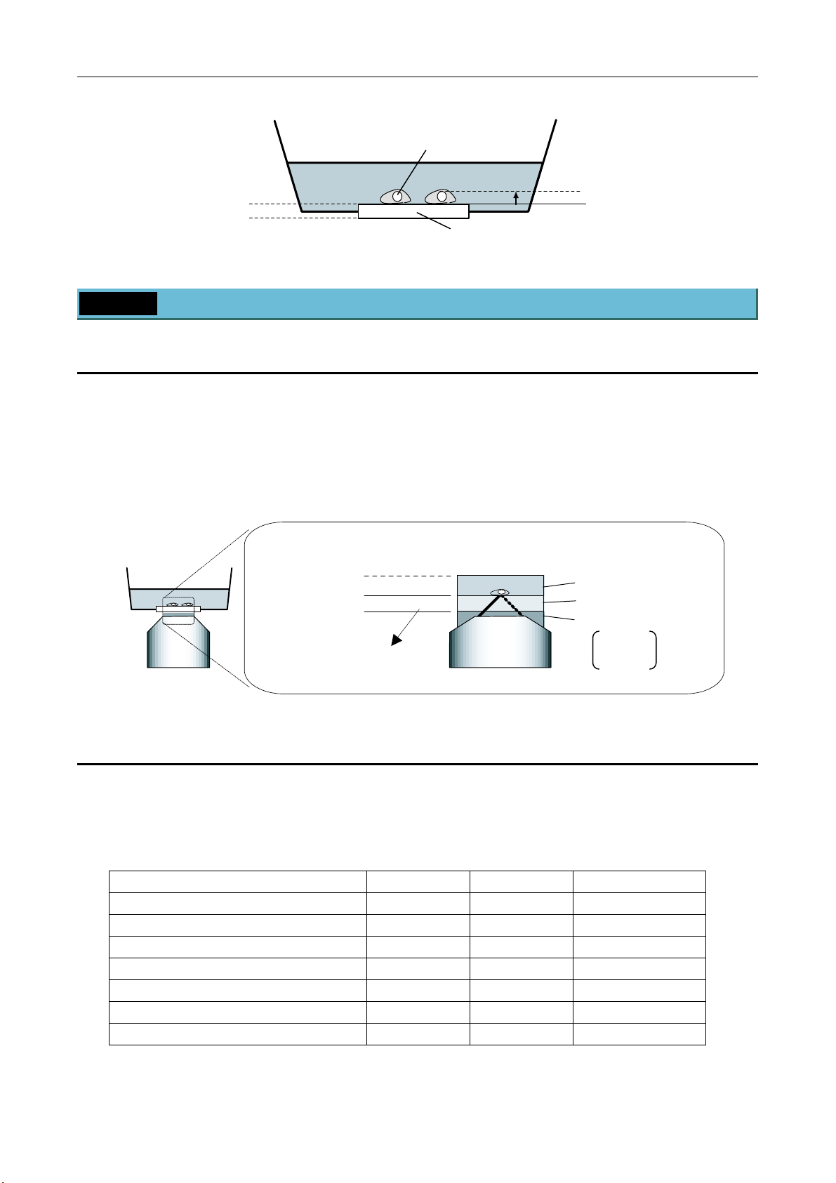
3 Offset function
This system detects the boundary surface between the cover glass and aqueous solution of the specimen using a near
infrared light (infrared band) and controls focusing using the boundary surface as the reference position.
The objective of the microscope tracks the up/down changes of the boundary surface caused by the defocusing over
time and the stage movement when controlling the focus.
To focus on a desired point on the specimen, adjust the OFFSET knob on the perfect focus controller.
The offset amount is defined as the deviation of the focus point from the reference position (boundary surface) to where
the focus point is moved by adjusting the OFFSET knob. Keeping the specified offset amount, focusing can be controlled
so as to track the up/down changes of the boundary surface. The range of the offset amount depends on the objective. In
particular, when a water or oil immersion type objective is used, the offset amount is limited in the downward.
8
I Overview
Specimen
Detected boundary surface
(water or oil immersion)
Detected boundary surface
(dry type)
Aqueous solution
Cover glass
4 Specimen
4.1 Suitable specimen
Cells touching the upper surface of the cover glass of the glass bottom dish
Cover glass thickness: 150 to 180 µm (No.1S)
refractive index: 1.5
Aqueous solution (culture solution) depth: 3 mm or more
refractive index: 1.33 or near
Boundary surface
(water or oil immersion)
Boundary surface
(dry type)
t = 165±15 µm
(Standard: No.1S)
≥ 3 mm
t
Offset amount
Refractive index
Culture solution: up to 1.35
Cover glass: up to 1.5
Water: 1.33
Oil: 1.514
Air: 1.0
4.2 Suitable objectives
The following objectives are suitable for this system. If another objective is attempted to be used, an error will occur and
the LED of the [Obj Err] on the perfect focus controller will be lit.
If the LED of the [Obj Err] is lit, refer to the VII. Troubleshooting.
Name NA WD (mm) Type
Plan Fluor 40x 0.75 0.72 dry
Plan Fluor 40xH 1.30 0.2 oil immersion
Plan Fluor ELWD 20xC 0.45 7.6 dry
Plan Fluor ELWD 40xC 0.6 2.9 dry
Plan Fluor ELWD DM 20xC 0.45 7.6 dry
Plan Fluor ELWD ADL 20xC 0.45 7.6 dry
Plan Fluor ELWD ADL 40xC 0.6 2.9 dry
9

I Overview
Name NA WD (mm) Type
Plan Apo VC 60xH 1.40 0.13 oil immersion
Plan Apo VC 100xH 1.40 0.13 oil immersion
Plan Apo VC 60xWI 1.20 0.27 water immersion
Plan Apo 60xHA 1.40 0.21 oil immersion
Plan Apo 100xH 1.40 0.13 oil immersion
Plan Apo 60xWI 1.20 0.22 water immersion
Plan Apo 20x 0.75 1.00 dry
Plan Apo DM 60xH 1.40 0.21 oil immersion
Plan Apo DM 100xH 1.40 0.13 oil immersion
Plan Apo TIRF 60x 1.45 0.13 oil immersion
4.3 Not-suitable specimen
The following specimens are hard to be observed. Because the focus control cannot be performed by reason of that the
reflection signal of the infrared is weak or the scattered light is strong.
(1) Fixed specimen
Usually a fixed specimen is filled with mounting medium. And this medium has a high refractive index. So, the
difference of the refractive indexes between the cover glass and the specimen is relatively small. Therefore,
enough reflection for the detection cannot be get.
(2) Sliced specimen
A sliced specimen is thick and its scattered light is strong. So, the reflection is hard to detect because the reflection
from the boundary surface is relatively weak.
(3) Specimen of strong reflection or strong light scattering
In addition to the sliced specimen, if a specimen has a strong light scattering, the weak reflection from the boundary
surface is hard to detect as is the case of (2).
(4) Cells touching the bottom glass with the thickness of 170 µm or more
When a dry type objective is used for a specimen with a thick bottom glass, the offset amount may be insufficient to
observe the boundary surface. So, the focusing range cannot be secured. (For an oil immersion type objective, the
boundary surface may be detected. But this method is not recommend. Use the cover glass of No.1S.)
(5) Specimen mounted on a plastic dish
A plastic dish is not recommended because the boundary surface is not suitable for the detection.
(6) Specimen mounted on a dirty cover glass
This system detects the surface of the cover glass and controls focusing. So, if the surface of the cover glass is not
clean, it will adversely affect the detection. Please clean the cover glass beforehand.
10
II
Name and Function of Each Part
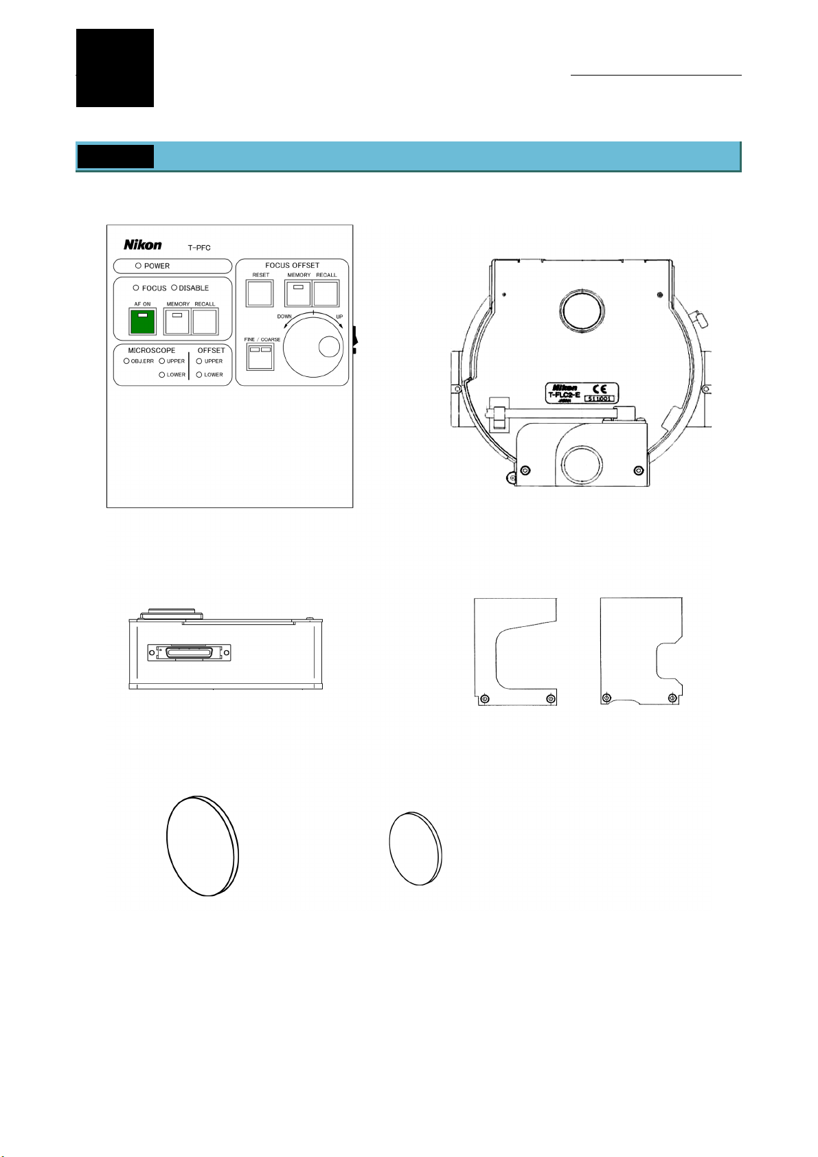
1 Name of Each Part
T-PFC perfect focus controller
T-PFB perfect focus module
T-FLC2-E motorized cassette holder
T-PFB perfect focus module pillars
IR-CUT filter of 45 mm diameter IR-CUT filter of 25 mm diameter
11
 Loading...