


M314E 04.7.CF.3(1/5)
Inverted Microscope
ECLIPSE TE2000-E
ECLIPSE TE2000-U
ECLIPSE TE2000-S
Instructions
Thank you for purchasing the Nikon products.
This instruction manual is written for the users of the Nikon’s inverted microscopes “ECLIPSE TE2000-E, ECLIPSE TE2000-U, ECLIPSE TE2000-S” and describes the basic operations of the microscope.
To ensure correct usage, read this manual carefully before operating the instrument.
•It is prohibited to reproduce or transmit this manual in part or whole without Nikon’s expressed permission.
•The contents of this manual are subject to change without notice.
•Although every effort has been made to ensure the accuracy of this manual, if you note any points that are unclear or incorrect, contact your nearest Nikon representative.
•Some of the products described in this manual may not be included in the set you have purchased.
•Be sure to read the instruction manual for any other products used in combination with the microscope.
•If you purchased the TE2000-E model, be sure to read the instruction manual supplied with the T-HUBC HUB controller.
•If you are using the TE2000-U/S together with the T-HUBC HUB controller, be sure to read the instruction manual supplied with the T-HUBC HUB controller.
Warning / Caution symbols used in this manual
Although Nikon products are designed to provide you with the utmost safety during use, incorrect usage or disregard of the instructions can cause personal injury or property damage and will lead to the forfeiture of all claims against warranty. For your safety, read the instruction manual carefully and thoroughly before using the instrument. Do not discard this manual but keep it near the product for easy reference.
In this manual, safety instructions are indicated with the symbols shown below. Be sure to follow the instructions indicated with these symbols to ensure correct and safe operation.
Symbol |
Meaning |
|
|
|
Disregarding instructions marked with this symbol may lead to death or serious |
|
|
|
|
|
injury. |
|
|
Disregarding instructions marked with this symbol may lead to injury or property |
|
|
|
|
|
|
|
|
damage. |
|
|
|
Meaning of symbols used on the equipment
The symbol appearing on the product indicates the need for caution at all times during use.
Always refer to the instruction manual and read the relevant instructions before manipulating any part to which the symbol has been affixed.
Symbol Meaning
Caution for heat.
This marking at the top part of the Dia-illuminator and the 12V100W lamphouse calls your attention on the following;
•Lamphouse becomes very hot during and immediately after the illumination.
•Risk of burns. Do not touch the lamphouse during and immediately after the illumination.
•Make sure that the lamphouse is sufficiently cool before the lamp replacement.
Biohazard
This symbol on the stage calls your attention to the following:
•Spillage of a sample from a vessel onto the microscope presents a biohazard risk.
•To avoid biohazard contamination, do not touch the contaminated portion with your bare hands.
•Decontaminate the contaminated portion according to the standard procedure of your laboratory.
1

1.Intended use of the equipment.
This microscope is intended mainly for use in microscopic observation and in the micromanipulation of living cells and tissue using diascopic (transmitted) and episcopic (reflected) illumination. It is designed for the main purposes of experimentation and observation, in hospitals or other laboratories, of such cells and tissue within the fields of genetics, immunology, physiology, pharmacology, neurology, cellular biology, and molecular biology.
2.Do not disassemble.
Disassembly may cause malfunction and / or electrical shock, and will lead to the forfeiture of all claims against warranty. Do not disassemble any part other than those described in this manual. If you experience any problem with the microscope, notify your nearest Nikon representative.
3.Check the Input Voltage.
This microscope uses a power supply for the lamp.
When using the power supply TE-PS30 or TE-PSE30:
Make sure that the input voltage indication on the rear panel matches your regional voltage supply. If the voltages do not match, do not use the microscope; instead, notify your nearest Nikon representative. Using the power supply with the wrong input voltage may cause a short circuit or fire. It may also cause damage to the microscope.
When using the power supply TE2-PS100W:
If you are using the power supply TE2-PS100W, there is no need to check the input voltage since the input voltage of this power supply is AC 100-240V and can be used at any place in the world.
4.Check the AC adapter of the HUB controller (when using the T-HUBC HUB controller).
The HUB controller is powered by the AC adapter. Be sure to use the specified adapter model meeting the requirements given below. Use of any other type of adapter can result in malfunction, excessive heating, and/or fire.
•To prevent malfunction and/or fire, be sure to use the AC adapter in a well-ventilated location. To ensure that it radiates heat properly and does not overheat, never cover or place any object on the adapter.
•To prevent malfunction, always turn off the power switch (switch to “O”) of the HUB controller before attaching the AC adapter.
•Specified AC adapter
Manufacturer: |
PHIHONG ENTERPRISE (Taiwan) |
Model: |
PSA30U-120 (N) |
Rated input voltage: |
AC 100-240 V, 0.7 A, 50/60 Hz |
Voltage fluctuation: |
±10% |
Rated output voltage: DC 12 V
Rated output current: 2.5 A
Others: UL Listed product, GS approved, CE satisfied
5.Power cord for power supply and the power cord for AC adaptor of the HUB controller
To prevent electric shock, always turn off the power switch (switch to “O”) for the power supply and the HUB controller before attaching or detaching the power cord. Use one of the power cords specified below. Use of an improper power cord can result in fire or other hazard. Also note that the power supply is classified as subject to protection class I against electric shock. Therefore, be sure to connect it to a protective ground terminal.
•Using units in areas where the supply voltage is 100 to 120 V
UL Listed detachable power cord set, 3 conductor grounding Type SVT, No. 18 AWG, 3 m long maximum, rated at 125 V AC minimum.
•Using units in areas where the supply voltage is 220 to 240 V
Approved according to EU/EN standards, 3 conductor grounding Type HO5VV-F, 3 m long maximum, rated at 250 V AC minimum.
6.Heat from the light source.
•The lamp and the lamphouse become extremely hot by the lamp illumination. To avoid burns, do not touch the lamphouse while the lamp is lit or for thirty minutes after it has been turned off.
•To avoid the risk of fire, do not place fabric, paper or highly flammable volatile materials such as gasoline, petroleum benzine, paint thinner or alcohol near the lamphouse while the lamp is lit or for about thirty minutes after it has been turned off.
•The bottom plate of the power supply becomes hot during use. Do not cover up the ventilation holes on the side of the power supply.
Continued on the next page
2

7.Hazardous sample
This microscope is mainly for use in microscopic observation and micromanipulation of living cells and tissue cultures in Petri dishes, microtiter plates, etc.
When handling a sample, check to determine whether the sample is hazardous. Handle hazardous samples according to the standard procedure of your laboratory. If the sample is of an infectious nature, wear rubber gloves to avoid infection, and be careful not to spill the sample. In the event of spillage of a sample from a vessel onto the microscope, decontaminate the contaminated portion according to the standard procedure of your laboratory.
1.Check the combination of the lamp, dia-illuminator and power supply.
The dia-illuminator and the power supply must be used in correct combination against the ratings of the lamp and the regional voltage supply. See page 38 to find out the correct combination of these items. Using the equipment in wrong combination will lead to fire, electric shocks or malfunction of the equipment.
2.Turn off the power during assembly, connection/disconnection of the cords, and lamp replacement.
To prevent electric shocks and/or malfunction, always turn off the power switch of the power supply and the T-HUBC HUB controller (flip it to the { side) and unplug the power cord from the wall outlet before assembly, connecting or disconnecting of the cords, and the lamp replacement.
3.Cautions on lamp replacement.
To avoid burns, wait at least 30 minutes after the lamp is turned off so that the lamp can cool sufficiently. To avoid electric shocks and malfunction, always turn off the power switch (flip it to the { side) and unplug the power cord from the wall outlet before lamp replacement.
Securely attach the lamphouse cover to the lamphouse after replacing the lamp. Never light the lamp while the lamphouse cover is open. Do not break used lamps; instead dispose of them as special industrial waste or according to the laws applicable to your municipal waste system.
4.Do not wet the microscope.
If the instrument gets wet, a short circuit may result that may cause malfunction or abnormal heating. If you accidentally spill a liquid on the instrument, immediately turn off the power switch (flip to the { side) and unplug the power cord from the wall outlet. Then use a dry cloth to wipe away the moisture. If any liquid gets inside the instrument, do not use it; instead, notify your nearest Nikon representative.
5.Weak electromagnetic waves.
This microscope emits weak electromagnetic waves. The accuracy of any precision electronic equipment may be adversely affected if positioned too close. If the microscope affects TV or radio reception, move the radio or TV further away from the microscope.
6.Cautions on assembling and installing the microscope.
•Be careful not to pinch your fingers or hands during the assembly.
•The scratches and dirt such as fingerprints on the optical parts (such as lens and filters) will adversely affect the microscope image. Be careful not to scratch or directly touch the lens and filters.
•This product is a precision optical instrument. Using or storing it under unsuitable conditions may damage it or may have an adverse effect on its accuracy. See the installation conditions on page 4 and use the product in an adequate environment.
7.Cautions on moving the microscope.
When moving the microscope, do not hold it by the focusing knobs, eyepiece tube, stage, dia-illuminator etc., since these parts can be damaged, or they could come off. Hold the microscope by the bottom front and bottom rear.
8.Be careful of the protruding rack of the T-SR rectangular stage.
The rack of the T-SR rectangular stage will protrude by the stage movement. Be careful not to strike your hands against the rack when reaching the focusing knobs or revolving nosepiece. You may get yourself hurt by the edge of the rack.
Continued on the next page
3

9.Disposal of the microscope
To avoid biohazard risk, dispose of the microscope as contaminated equipment according to the standard procedure of your laboratory.
Notes on handling the microscope
1.Handle the microscope gently.
This product is a precision optical instrument. Handle it carefully, and do not subject it to strong shocks. The precision of the objectives in particular can be adversely affected even by weak shocks.
2.Dirt on the lens.
The scratches and dirt such as fingerprints on the optical parts (such as lens and filters) will adversely affect the microscope image. If these parts get dirty, clean them following the instructions described on “Care and maintenance” at the end of this manual.
3.Dirt on the lamps.
Do not touch the lamp by bare hands. Dirt or fingerprints on the lamp will cause uneven illumination and shortens the life of the lamp. When handling lamps, wear gloves.
4.Installation location.
Using or storing the microscope under unsuitable conditions may damage it or may have an adverse effect on its accuracy. The following conditions should be kept in mind when selecting the installation location.
•Choose a flat surface with little vibration.
•Choose a location less exposed to hazards in the event of collisions, earthquakes, or other potential disasters. If required to keep the device from falling, use strong rope or other means to secure the microscope to the working desk or to another heavy, stable item.
•Avoid a brightly lit location such as a room that receives direct sunlight.
•Choose a location that is free from dust or dirt.
•Do not install the microscope in a warm (60°C or more), humid (85% or more) location. (Mold or condensation will form on the lenses and filters.)
•Leave enough space against the nearby wall since the lamphouse will become hot by lamp illumination.
•When using the “T-DH dia-illuminator 100W”, leave a certain space between the microscope and the nearby wall to allow the user to look at the caution symbols on the dia-illuminator and the lamphouse. If you are planning to use the tilting function of the “T-DH dia-illuminator 100W”, even more space is needed for the illuminator to tilt backward.
•The room light just above the microscope may come into the objective as an extraneous light. (Especially when using a condenser lens with longer working distance such as SLWD, ELWD and LWD lenses.) To avoid this, we recommend to turn off the room light above the microscope when observing the image.
5.Focusing knobs.
•Never turn the focus knobs on the left and right sides of the microscope in opposite directions at the same time, as doing so can result in damage to the microscope.
•Turning the coarse focus knob as far as it will go and then attempting to turn it further will result in damage to the microscope. Never use undue force to turn the knob.
•(For TE2000-E only) The coarse focus knob turns in sync with motorized Escape/Refocus movements. To prevent malfunctions, avoid contact with the coarse focus knob during motorized Escape/Refocus movements.
6.Protect the ports.
When not using any of the ports, be sure to attach the supplied cap to it. If not, extraneous light and dusts will enter the microscope.
4

Contents
Warning / Caution symbols used in this manual |
................................................... 1 |
||
Meaning of symbols used on the equipment ......................................................... |
1 |
||
|
|
............................................................................................................. |
2 |
|
|
............................................................................................................. |
3 |
Notes on handling the microscope........................................................................ |
4 |
||
I. |
Parts of the microscope and their names .................................................... |
6 |
|
|
1. |
Eyepiece tubes and eyepieces.................................................................... |
7 |
|
2. |
Microscope base....................................................................................... |
8 |
|
3. |
Dia-illuminators ...................................................................................... |
13 |
|
4. |
Condensers ............................................................................................ |
14 |
|
5. |
Stages, focusing module .......................................................................... |
15 |
|
6. |
Microscope rear ...................................................................................... |
16 |
|
7. |
Power supplies........................................................................................ |
17 |
II. |
Microscopy ................................................................................................ |
18 |
|
1.Microscope system consisting of TE2000-U, dia-illuminator 100W,
system condenser, and T-TD eyepiece tube D |
.............................................20 |
2.Microscope system consisting of TE2000-S, dia-illuminator 30W,
SLWD condenser, and T-TS eyepiece tube S |
................................................25 |
3.Microscope system consisting of TE2000-E, dia-illuminator 30W,
|
|
SLWD condenser, and T-TS eyepiece tube S................................................ |
29 |
|
4. |
Photomicrography (using a 35-mm camera mounted on the front port) ......... |
34 |
III. |
Operation of each part .............................................................................. |
37 |
|
|
1. |
Power ON/OFF ........................................................................................ |
38 |
|
2. |
Brightness adjustment............................................................................. |
39 |
|
3. |
Optical path switching.............................................................................. |
40 |
|
4. |
Using filters............................................................................................ |
42 |
|
5. |
Using field diaphragm .............................................................................. |
42 |
|
6. |
Using condenser aperture diaphragm......................................................... |
43 |
|
7. |
Eyepiece tube turret ................................................................................ |
44 |
|
8. |
System condenser................................................................................... |
44 |
|
9. |
Objectives.............................................................................................. |
45 |
|
10. |
Diopter adjustment ................................................................................. |
47 |
|
11. |
Focusing module ..................................................................................... |
47 |
|
12. |
T-DH dia-illuminator 100W ....................................................................... |
49 |
|
13. |
T-SR rectangular stage ............................................................................ |
50 |
|
14. |
Photomicrography ................................................................................... |
51 |
IV. |
Assembly................................................................................................... |
54 |
|
V. |
Troubleshooting ........................................................................................ |
61 |
|
VI. |
Care and maintenance............................................................................... |
64 |
|
VII. |
Technical specifications............................................................................. |
65 |
|
|
System diagram ........................................................................................ |
70 |
|
5
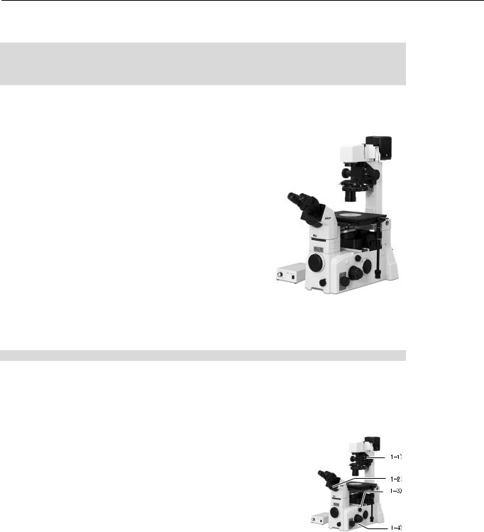
I. Parts of the microscope and their names
I. Parts of the microscope and their names
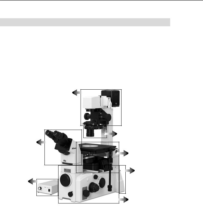
Parts of the microscope can be selected according to your purpose.
Exceptionally, the combination of the lamp, dia-illuminator and the power supply is fixed. Never use these parts in combination other than specified.
(Refer to page 38 for the correct combination of the lamp, dia-illuminator and the power supply.)
The T-HUBC HUB controller, which mounts on the rear side of the microscope, allows the user to control attached motorized units. For details, refer to the instruction manual provided with the T-HUBC HUB controller.
Dia-illuminator
P.13
Condenser
P.14
Eyepiece tube
P.7
Stage
P.15
Microscope rear P.16
Power supply P.17
Microscope base
P.8
This is a photograph of TE2000-U microscope with T-DH dia-illuminator 100W, LHS-H100P-1 12V100W lamphouse, 12V100W halogen lamp, TE2-PS100W power supply, T-SR rectangular stage, T-TD binocular eyepiece tube D, CFI 10X eyepieces, T-N6 sextuple nosepiece, system condenser, objectives, power cord, etc.
6
I. Parts of the microscope and their names
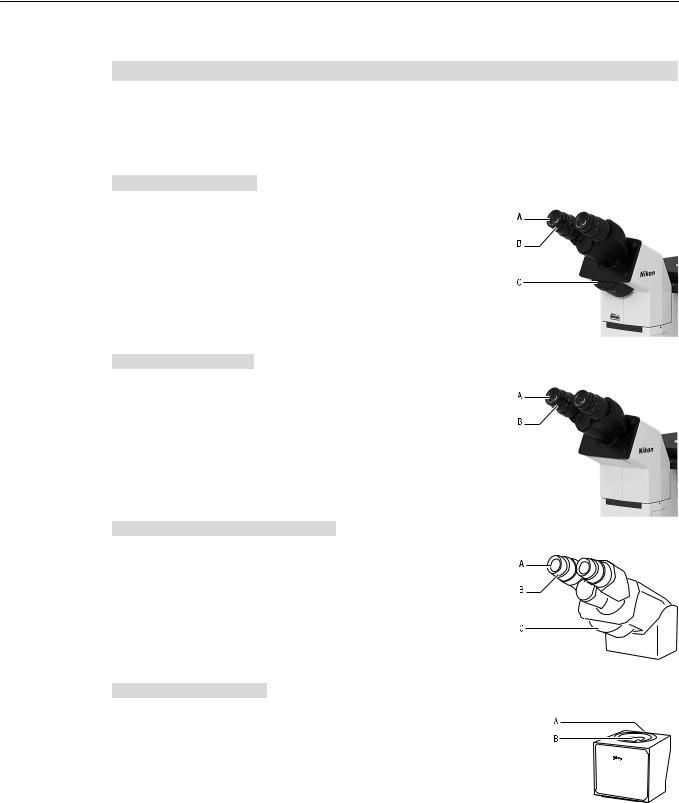
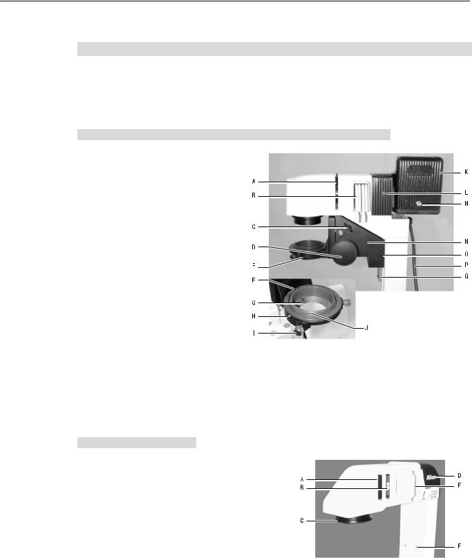
1. Eyepiece tubes and eyepieces
The following eyepiece tubes can be mounted on the observation port of the microscope.
T-TD eyepiece tube D
A:Diopter adjustment ring
B:Eyepiece
C: Eyepiece tube turret
O:Open
B:Bertrand lens (with focusing screw)
C: Close (Shutter)
M:2.5X magnifier
T-TS eyepiece tube S
A:Diopter adjustment ring
B: Eyepiece
T-TERG ergonomic eyepiece tube
A:Diopter adjustment ring
B:Eyepiece
C: Eyepiece tube turret
O:Open
B:Bertrand lens (with focusing screw)
C: Close (Shutter)
T-TI intermediate tube
A: Clamp screw for holding various devices
B: Mount for various devices such as
Trinocular eyepice tube for upright microscopes Teaching head
7
I. Parts of the microscope and their names
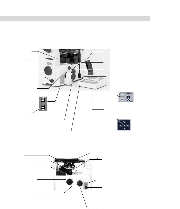
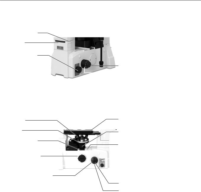
2.Microscope base
Note: Be sure to cover unused ports with supplied caps to prevent the entry of external light and dust.
TE2000-E, right side
Eyepiece-tube clamp screw
Observation port
Install the eyepiece tube.
Front port
Photo-mask dial
Clockwise turn: OUT
Counterclockwise turn: IN
Intermediate magnification dial
1X: No intermediate magnification
1.5X: 1.5X intermediate magnification for all ports
REFOCUS switch |
REFOCUS |
|
Raises the objective to the |
||
COARSE FOCUS |
||
memorized position. |
||
ESCAPE |
ESCAPE switch
Lowers the objective to the Escape position.
Fine focus knob
The distance of travel achieved by one rotation of the knob can be set to Fine, Middle, or Coarse.
The knob is set to Coarse at the factory.
T-RCP remote control pad
Not required when the microscope is controlled using a PC
T-HUBC HUB controller
The specified AC adapter is required.
Adapter clamp screw
Right-side port
Bottom port
 DIA-LAMP ADJ key
Used to adjust the view field brightness. This key can be used only
when the T-DH dia-illuminator 100W is installed.
Turn on the green indicators.
Light path key
Changes the optical path.
Observation 20% |
Observation 100% |
|
Front 80% |
||
|
||
Left 100% |
Observation 20% |
|
|
Right 80% |
|
|
Bottom 100% |
TE-2000E, left side
Objective
Nosepiece
Mount for analyzer
Install the analyzer here for DIC microscopy.
Adapter clamp screw
Left-side port
Optical path switch-over section holding screw
This screw is installed for transportation.
Be sure to remove the screw before using the microscope.
Stage
Black cover for elevating section
Remove the cover when installing the epi-fl attachment.
Mount for cassette holder
For the installation of the cassette holder for epi-fl microscopy
Dia-illumination ON/OFF switch
Brightness adjustment dial
This dial is disabled
when the remote control pad is used for bright adjustment.
Coarse focus knob
8
I. Parts of the microscope and their names
Note: Be sure to cover unused ports with supplied caps to prevent the entry of external light and dust.
TE2000-U, right side
Eyepiece-tube clamp screw
Observation port
Install the eyepiece tube.
Front port
Photo-mask dial
Clockwise turn: OUT
Counterclockwise turn: IN
Intermediate magnification dial
1X: No intermediate magnification
1.5X: 1.5X intermediate magnification for all ports
Optical path switch-over dial
1:Observation 100%
2:Observation 20%, Right 80%
3:Not used (Bottom port 100%)
4:Observation 20%, Front 80%
5:Left 100%
TE2000-U, left side
Adapter clamp screw
Right-side port
Fine focus knob
Coarse focus knob
Objective refocusing ring
Forward turn: Release Backward turn: Lock
Objective
Nosepiece
Mount for analyzer
Install the analyzer here for DIC microscopy.
Adapter clamp screw
Left-side port 
Coarse focus torque adjustment ring
Forward turn: Decreases torque
Backward turn: Increases torque
Stage
Black cover for elevating section
Remove the cover when installing the epi-fl attachment.
Mount for cassette holder
For the installation of the cassette holder for epi-fl microscopy
 Dia-illumination ON/OFF switch
 Brightness adjustment dial
This dial is disabled
when the remote control pad is used for bright adjustment.
Fine focus knob
Coarse focus knob
The bottom port changeover lever is provided on the left-hand side of the TE2000-U bottom port type. See P. 41 for optical path switching.
9
I. Parts of the microscope and their names
Note: |
Be sure to cover unused ports with provided caps to prevent the entry of external light and dust. |
Eyepiece-tube clamp screw
Observation port
Install the eyepiece tube.
Optical path switch-over dial
TE2000-S, right side
EYE: Observation 100%
SIDE: Observation 20%, Left 80%
Fine focus knob
 Coarse focus knob
TE2000-S, left side
Objective
Nosepiece
Mount for analyzer
Install the analyzer here for DIC microscopy.
Adapter clamp screw
Left-side port
Coarse focus torque adjustment ring
Forward turn: Decreases torque
Backward turn: Increases torque
Stage
Black cover for elevating section
Remove the cover
when installing the epi-fl attachment.
Mount for cassette holder
For the installation of the cassette holder for epi-fl microscopy
 Dia-illumination ON/OFF switch
 Brightness adjustment dial
This dial is disabled
when the remote control pad is used for bright adjustment.
Fine focus knob
Coarse focus knob
10

I. Parts of the microscope and their names
Various adapters for the front port (TE2000-S is not equipped with front port.)
T-BFA F-mount adapter
Digital still camera with F-mount such as D1 can be mounted.
T-BSLR SLR camera adapter
Single-lens reflex camera such as FE10, F70, F90 and F5 can be mounted.
T-BDCA direct C-mount adapter
Digital still camera for the microscopes such as DXM1200, can be mounted here.
Various adapters for side port
Side port adapter
This adapter is supplied with the microscope.
T-BPA photo adapter
Double port adapter
Various TV adapters
Various adapters for bottom port
(TE2000-U, except for the bottom-port type, and TE2000-S are not equipped with bottom port)
Bottom port adapter
This adapter is supplied with the microscope.
Various TV adapters
11
I. Parts of the microscope and their names
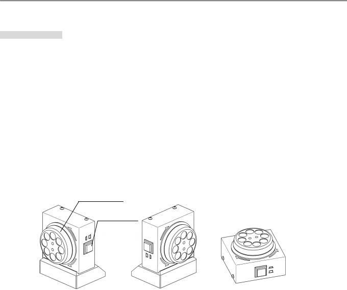
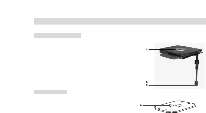
T-EFN Focus Knob
(supplied with the TE2000-E only. The knob is incompatible with the TE2000-U and TE2000-S.)
The TE2000-E provides focus adjustment in various positions with the supplied T-EFN focus knob. You can make fine focus adjustments by connecting the T-EFN focus knob to the T- HUBC HUB controller AUX connector and by switching the knob selector switch on. (Switching the selector switch off permits fine focus adjustments using the fine movement knob provided on the right side of the TE2000-E.)
The T-EFN focus knob is comprised of the focus knob main unit and the base plate, which are connected by a magnet.
The direction of the T-EFN focus knob can be switched between right and left by changing the main unit's position relative to the base plate. Note that the focus adjustment knob can be operated independently with the knob facing up.
Knob rightward rotation (clockwise): Raises the objective (brings the objective closer to the specimen).
Knob leftward rotation (counterclockwise): Lowers the objective (moves the objective farther from the specimen).
Fine movement
.
Selector switch
Knob facing left |
Knob facing right |
Knob facing up |
Caution: The T-EFN focus knob main unit and the base plate are connected by a magnet. Handle carefully. Lifting them while they are connected may cause the base plate to detach and fall.
12
I. Parts of the microscope and their names
3. Dia-illuminators
Dia-illuminators should be used in specified pairs with the lamp (12V100W or 6V30W). A lamphouse is needed for the T-DH dia-illuminator 100W.
T-DH dia-illuminator 100W and LHS-H100P-1 12V100W lamphouse
A:Field aperture diaphragm lever
B:Filter sliders
C: Condenser refocusing clamp (Works only when LWD condenser lens is attached.)
D: Condenser focus knob E: Condenser clamp screw
F: Condenser mount positioning pin G: Condenser mount positioning groove H: Condenser mount rotation clamp
screw
I:Condenser centering screw
J:Condenser mount (rotatable)
K: LHS-H100P-1 12V100W lamphouse
L: Lamphouse clamp screw
M:Lamphouse cover clamp screw
N:Condenser holder (removable)
O:Condensr holder clamp screw
P:Lamp cable
Q:Condenser holder fall-stop screw
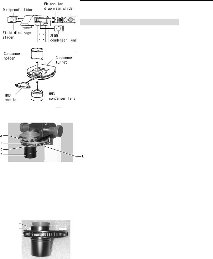
T-DS dia-illuminator 30W
A: Dustproof slider (removable)
B: F stop slider (removable)
C: Condenser mount
D:6V30W lamp housing
E:Filter slider
F:M4 screw holes for additional device mounting
13
I. Parts of the microscope and their names
4. Condensers
System condenser
When mounted on |
When mounted on T-DS dia-illuminator 30W |
T-DH dia-illuminator 100W |
(Only for HMC observation.) |
A:Condenser aperture diaphragm
B:Condenser module
C:Condenser module clamp screw
D:Condenser lens
(3 types available; ELWD, LWD, HMC)
E:Annular diaphragm centering screw (on Ph modules only)
ELWD-S condenser |
|
SLWD condenser |
A Centering handle clamp screw
B Centering handle
C Turret
A
B
C
SLWD condenser can only be mounted on
T-DS dia-illuminator 30W.
14
I. Parts of the microscope and their names
5.Stages, focusing module
T-SR rectangular stage
A: Stage ring
B: Y-axis stage movement knob
C: X-axis stage movement knob
T-SP plain stage
A: Stage ring
15

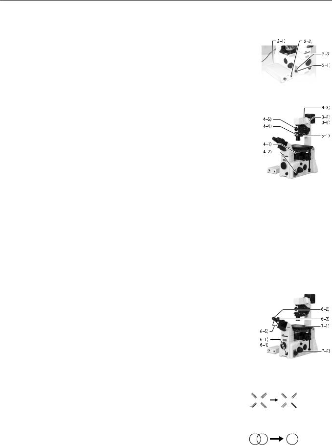
I. Parts of the microscope and their names
6.Microscope rear
Mount for epi-fl attachment
Mount for T-HUBC HUB controller
LAMP CTRL connector Connect the power supply or HUB controller.
MIC CTRL1 connector
Connect the HUB controller. Not provided on TE2000-U or TE2000-S
MIC CTRL2 connector
Connect the HUB controller. Not provided on TE2000-U or TE2000-S
The photo shows the T-HUBC HUB controller and epi-fl attachment installed to the rear side of the microscope. (The HUB controller's connectors are attached with various motorized units.)
Epi-fl attachment
NOSEPIECE
Connect the T-ND6-E sextuple motorized DIC nosepiece.
ANALYZER
Connect the T-A-E motorized DIC analyzer
EX FILTER
Connect the T-FLEW-E EX filter wheel.
FL SHUTER
Connect the T-FL-E motorized epi-fl attachment.
REMOTE
Connect the T-RCP remote control pad.
T-HUBC HUB controller
This device controls
the attached motorized units. It must be installed when the TE2000-E is used.
Installation of this controller is optional on the TE2000-U and TE2000-S.
CONDENSER
Connect the T-CT-E motorized condenser turret.
FL BLOCK
Connect the T-FLC-E motorized cassette holder.
BA FILTER
Connect the T-FLBW-E
BA filter wheel.
AUX
Connect the T-EFN focus knob here. (The T-EFN focus knob is supplied with the TE2000-E only.)
 SHUTTER
Refer to "VI-21 Connection of external equipment"
in the instruction manual supplied with the HUB controller.
STAGE
Refer to "VI-21 Connection of external equipment"
in the instruction manual supplied with the HUB controller.
TE-PS
Connect the power supply.
PC
Connect a PC.
EXP
Refer to "VI-22 Connection to the EXP connector"
in the instruction manual supplied with the HUB controller.
16
I. Parts of the microscope and their names
7.Power supplies
The bottom of the power supply becomes hot while it is in use. Do not obstruct the air vents on the sides of the power supply.
TE2-PS100W power supply
EXTERNAL switch
Turning the switch ON activates the brightness adjustment dial on the microscope or the DIA-LAMP adjustment key on the T-RCP remote control pad (when the T-DH dia-illuminator 100W is used).
Turning this switch OFF activates the brightness adjustment dial on the power supply.
Pilot lamp
Turns on when the power is on.
Pin 2 : ditto
OUTPUT connector
This is the lamp output connector.
Connect the lamp cable from the dia-illuminator to this connector.
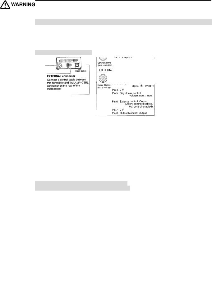
TE-PS30 power supply (for 100−120 V area)
TE-PSE30 power supply (for 220−240 V area)
CTRL connector
Connect the LAMP CTRL connector on the rear of the microscope using a control cable. This device cannot be used to connect the T-HUBC HUB controller.
Pin 3 : Lamp ON/OFF: Input
(Open: ON, 0 V: OFF)
Pin 4 : 0 V
17
II. Microscopy
II.Microscopy
When using the system consisting of the TE2000-E and dia-illuminator 100W
For the microscopy procedure, refer to the instruction manual supplied with the T-HUBC HUB controller.
The T-HUBC HUB controller, which mounts on the rear of the microscope, controls the operations of all attached motorized units. Note that when the T-HUBC HUB controller is mounted on the rear of the microscope, the microscope cannot be operated in the same way as when manual operation is used. Be sure to read the instruction manuals supplied with the T-HUBC HUB controller and T-RCP remote control pad to ensure proper preparation and operation of the microscope.
Note that the following two operations cannot be controlled using the T-HUBC HUB controller.
•6V30W lamp ON/OFF: Use the dia-illumination ON/OFF switch on the microscope main body.
•6V30W lamp voltage adjustment: Use the brightness adjustment dial on the microscope main body or power supply.
When using the TE2000-U or TE2000-S
with the T-HUBC HUB controller mounted on the rear
For the microscopy procedure, refer to the instruction manual supplied with the T-HUBC HUB controller.
The T-HUBC HUB controller, which is mounted on the rear of the microscope, controls the operations of all attached motorized units. Note that when the T-HUBC HUB controller is mounted on the rear of the microscope, the microscope cannot be operated in the same way as when manual operation is used. Be sure to read the instruction manuals supplied with the T-HUBC HUB controller and T-RCP remote control pad to ensure proper preparation and operation of the microscope.
Note that the following five operations cannot be controlled using the T-HUBC HUB controller.
•Optical path switchover: Use the optical path switchover dial on the microscope main body.
•Vertical focus motion control from PC: Use the fine/coarse focus knob on the microscope main body.
•Z-axis display: The Z-axis position data cannot be obtained.
•6V30W lamp ON/OFF: Use the dia-illumination ON/OFF switch on the microscope main body.
•6V30W lamp voltage adjustment: Use the brightness adjustment dial on the microscope main body or power supply.
18
II. Microscopy
The TE2000 series is the system microscopes that can be flexibly configured to meet specific applications. There are three main body types, two types of dia-illuminators, four types of eyepiece tubes, and various other parts variations. The following section describes the basic microscopy procedure based on three standard system configurations.
•Refer to "III. Operation of each part" for details on each operation.
•If your microscope is configured differently from the system described in the manual, refer to the applicable explanations in "III. Operation of each part."
•If your microscope is not pre-assembled, see "IV. Assembly" first.
•If your microscope is mounted with the epi-fl, DIC, or other attachments, refer to the instruction manuals supplied with the respective attachments.
1.Microscope system consisting of TE2000-U, dia-illuminator 100W, system condenser, and T-TD eyepiece tube D
1-1. Bright-field microscopy
1-2. Phase-contrast microscopy
2.Microscope system consisting of TE2000-S, dia-illuminator 30W, SLWD condenser, and T-TS eyepiece tube S
2-1. Bright-field microscopy
2-2. Phase-contrast microscopy
3.Microscope system consisting of TE2000-E, dia-illuminator 30W, SLWD condenser, and T-TS eyepiece tube S
3-1. Bright-field microscopy
3-2. Phase-contrast microscopy
4.Photomicrography (using a 35-mm camera mounted on the front port)
Microscope system consisting of TE2000-U, dia-illuminator 100W, system condenser, and T-TD eyepiece tube D
Supplementary information
When conducting bright-field or phase-contrast microscopy with a microscope system consisting of the TE2000-E, dia-illuminator 100W, system condenser, and T-TD eyepiece tube D, refer to the instruction manual supplied with the T-HUBC HUB controller since it provides detailed information.
Before using the instrument, read the "WARNING," "CAUTION," and "Notes on handling the microscope" sections at the beginning of this manual and be sure to follow the instructions therein.
Also refer to the instruction manuals supplied with other products (such as the epi-fl and DIC attachments) used in combination with the microscope, and follow the instructions written.
19
II. Microscopy
1.Microscope system consisting of TE2000-U, dia-illuminator 100W, system condenser, and T-TD eyepiece tube D
The following instructions are based on a microscope equipped with the parts listed below.
TE2000-U microscope T-TD eyepiece tube D CFI 10X eyepiece
T-DH dia-illuminator 100W LHS-H100P-1 12V100W lamphouse 12V100W halogen lamp TE2-PS100W power supply System condenser
LWD condenser lens
Condenser module for bright-field microscopy Condenser module for phase-contrast microscopy
T-SR rectangular stage T-N6 sextuple nosepiece
Objectives for bright-field microscopy Objectives for phase-contrast microscopy Others
1-1. Bright-field (BF) microscopy
Key point: Detach all optical elements required for other types of observation from the optical path. Position the condenser correctly (adjust the focus and centering), and adjust the clarity of the image by moving the “aperture diaphragm”.
1.Reset the convenient functions.
1)Turn the “condenser refocusing clamp” on the diailluminator counterclockwise to release.
2) Set the “eyepiece tube turret” to position < O >.
3) Set the “intermediate magnification dial” on the right side of the microscope to position < 1X >.
4) Turn the “objective refocusing ring” behind the fine/coarse focus knob on the right side of the microscope counterclockwise to release.
20
II. Microscopy
2.Turn on the dia-illumination.
1) Set the “EXTERNAL switch” on the rear side of the power supply to ON.
2) Turn on the “power switch” of the power supply. (Flip the switch to .)
3)Press the “dia-illumination ON/OFF switch” on the left side of the microscope to turn on the lamp.
3.Adjust the lamp to ensure color fidelity.
1) Set the “brightness adjustment dial” on the left side of the microscope to the < 12V100W > indication.
2) Move the “NCB11 filter” on the dia-illuminator into the optical path.
3) Move the “ND4 filter” on the dia-illuminator into the optical path.
4.Adjust the optical path.
1)Move the < 10X > objective into the optical path.
2)Set the “optical path switchover dial” on the right side of the microscope to position < 1 >. (-> Direct 100% light to the observation port.)
3)Raise the “field diaphragm lever” on the dia-illuminator completely to open the field diaphragm fully.
4)Turn the “aperture diaphragm lever” on the system condenser to the right limit to open the “aperture diaphragm” fully.
5)Turn the condenser focus knob to lower the condenser mount to the lowest position.
Supplementary information
When the system condenser is mounted with the “ELWD condenser lens”, position the condenser mount at the location about 1 cm below the uppermost position. When using the “ELWD-S condenser”, position the condenser mount at the location about 2 cm below the uppermost position.
5.Set the microscope for bright-field microscopy.
1)Set the “condenser turret” to position < A >.
6.Adjust the diopter and interpupillary distance.
1)Turn the “photo-mask dial” on the front side of the microscope counterclockwise to move the photo-mask into the optical path.
2)Look into the left eyepiece with your left eye. Turn the “diopter adjustment ring” of the left eyepiece to bring the double crosshairs of the photo-mask into focus.
3)Look into the right eyepiece with your right eye. Turn the “diopter adjustment ring” of the right eyepiece to bring the double crosshairs of the photo-mask into focus.
Turn the diopter adjustment ring
so that the double crosshairs come into focus.
Adjust the interpupillary distance
to consolidate the view fields of both eyepieces.
21
 Loading...