

Page 1
SUPERSCRIPT
User’s Guide
™
750C
Page 2

Copyright © 1997, NEC Technologies Publication issued by:
NEC Technologies, Inc.
All rights reserved 1250 N. Arlington Heights, Suite 500
Itasca, IL 60143
NEC Technologies reserves the right to modify the equipment described in this manual at any time and without notice.
TRADEMARKS
Any trademarks and/or proprietary names indicated are the property of their respective owners.
Printed in Italy
NOTICE: NEC Technologies makes no representations or warranties with respect to the contents of this document and
specifically disclaims any implied warranties of fitness for any particular purpose. The information contained in this document is
accurate to the best of our knowledge, but NEC Technologies is not liable for errors or misinterpretations.
Page 3
IIIIIIIVVVIVII
Page 4
Page 5
Page 6
Page 7
Page 8
Page 9
Page 10
VIIIIXXXIXII
Page 11
Page 12
Page 13
Page 14
Page 15

NEC Technologies, Inc.
1250 N. Arlington Heights
NEC
Suite 500
Itasca, IL 60143
NECTECH SOFTWARE LICENSE AGREEMENT
PLEASE CAREFULLY READ THE FOLLOWING TERMS AND CONDITIONS BEFORE
OPENING THIS SOFTWARE PACKAGE: OPENING THE PACKAGE INDICATES THAT YOU
HAVE ACCEPTED THESE TERMS AND CONDITIONS. IF YOU DO NOT AGREE WITH
THEM, YOU SHOULD IMMEDIATELY RETURN THE PACKAGE UNOPENED AND THE
PRODUCT UNUSED TO THE PERSON FROM WHOM YOU PURCHASED THE PACKAGE
WITHIN A REASONABLE PERIOD OF TIME FOR A FULL REFUND OF MONEY PAID FOR
THE PACKAGE.
NECTECH provides the Software and licenses its use to you, the licensee, pursuant to the following
terms. (From this time on, references to “you” mean the “licensee”, references to “NECTECH”
mean “NEC Technologies, Inc.”, references to “Printer” mean the printer product purchased with the
Software, and references to the “Software” mean the software programs, including the coded font
programs, in the medium (e.g., floppy disk, CD-ROM) of this package and/or in the ROM of the
Printer and any other enhancements to the Software which you hereafter may acquire from
NECTECH unless such acquisition is subject to another written license agreement.)
You assume responsibility for the selection of the Software to achieve your intended results.
Further, you are responsible for the installation, use and results obtained from the Software.
LICENSE
(1) NECTECH grants to you a nonexclusive and royalty-fee license, subject to these sections (1)
through (4) and the other provisions hereof:
(a) to use on the Printer one (1) copy of that portion of the Software which is provided to you
preinstalled in the ROM of the Printer;
(b) to use on up to five (5) computers connected to the printer that portion of the Software
included in the medium of this package; and
(c) to use the typeface trademarks used by NECTECH to identify the coded font programs and
typefaces produced therefrom, provided that you can only use such trademarks to identify
printed output produced by the coded font programs.
You may not rent or lease the Software, but you may transfer the Printer, the Software and
accompanying documentation on a permanent basis, provided that you retain no copies of the
Software and the recipient agrees to be bound by all of the terms and conditions of this Agreement.
(2) You agree not to alter, reverse engineer or disassemble the Software. You will not copy the
Software except as necessary to use them on computers and the Printer described in section (1)
above or backup purposes. You agree that any such copies of the Software shall contain the same
proprietary notices that appear on and in the Software.
(3) Title to and ownership of the Software, related documentation and any reproduction thereof shall
remain with NECTECH and its suppliers and the trademarks are the property of such trademark
owners. Except as stated in section (1) and (2) above, this Agreement does not grant to you any
right (whenever by license, ownership or otherwise) in or to patents, copyrights, trade secrets,
trade names, trademarks or any other intellectual property right with respect to the Software.
(4) You will not export or re-export the Software without the appropriate United States or foreign
government licenses.
COPYRIGHT
THE SOFTWARE IS COPYRIGHTED AND, EXCEPT AS PERMITTED BY THIS
AGREEMENT, YOU MAY NOT DUPLICATE THE SOFTWARE OR DISCLOSE IT TO ANY
OTHER PARTY.
TERM
This Agreement is effective until terminated. You may terminate it voluntarily at any time.
Voluntary termination by you must be accompanied by complete destruction of the Software and
copies thereof. NECTECH or its suppliers may terminate this Agreement without notice upon your
failure to abide by this Agreement.
LIMITED WARRANTY
(1) NECTECH warrants to you that each medium (floppy disk, ROM and/or CD-ROM) containing
the Software is free from defects in materials and workmanship and also warrants that it will
replace any defective medium at no charge to you, if any such defective medium is returned to
NECTECH within ninety (90) days of your purchase. (Any such return should be made to
NECTECH at the address on this Agreement. “Attention: Printer Software Marketing”, together
with a written notification of the defect.)
(2) YOU AGREE THAT THE SOFTWARE IS PROVIDED AND LICENSED “AS IS”. TO THE
MAXIMUM EXTENT PERMITTED BY APPLICABLE LAW, NECTECH AND ITS
SUPPLIERS DISCLAIM ALL OTHER WARRANTIES, EITHER EXPRESS OR IMPLIED,
INCLUDING, BUT NOT LIMITED TO, IMPLIED WARRANTIES OF MERCHANTABILITY
AND FITNESS FOR A PARTICULAR PURPOSE, WITH REGARD TO THE SOFTWARE.
YOU BEAR THE ENTIRE RISK RELATING TO THE QUALITY OF THE SOFTWARE AND,
IF THE SOFTWARE PROVES TO HAVE ANY DEFECTS, YOU ASSUME THE COST OF
ANY NECESSARY SERVICING OR REPAIRS.
(3) SOME STATES DO NOT ALLOW THE EXCLUSION OF IMPLIED WARRANTIES, SO
THAT THE ABOVE EXTENSION MAY NOT APPLY TO YOU. THIS WARRANTY GIVES
YOU SPECIAL LEGAL RIGHTS AND YOU MAY ALSO HAVE OTHER RIGHTS WHICH
VARY FROM STATE TO STATE.
LIABILITY
TO THE MAXIMUM EXTENT PERMITTED BY APPLICABLE LAW, IN NO EVENT SHALL
NECTECH OR ITS SUPPLIERS BE LIABLE FOR ANY DAMAGES WHATSOEVER
(INCLUDING, WITHOUT LIMITATION, LOSS OF USE, LOSS OF PROFIT, INTERRUPTION
OF BUSINESS, OR ANY INDIRECT, SPECIAL, INCIDENTAL OR CONSEQUENTIAL
DAMAGES OF ANY KIND) REGARDLESS OF THE FORM OF ACTION WHETHER IN
CONTRACT, TORT (INCLUDING NEGLIGENCE), STRICT PRODUCT LIABILITY OR
OTHERWISE, EVEN IF NECTECH HAS BEEN ADVISED OF THE POSSIBILITY OF SUCH
DAMAGES. BECAUSE SOME STATES DO NOT ALLOW THE EXCLUSION OR
LIMITATION OF LIABILITY FOR INCIDENTAL OR CONSEQUENTIAL DAMAGES, THE
ABOVE LIMITATIONSMAY NOT APPLY TO YOU.
THIS AGREEMENT SHALL BE CONSTRUED AND INTERPRETED ACCORDING TO THE
LAWS OF THE COMMONWEALTH OF MASSACHUSETTS.
Page 16

This Page Intentionally Blank
Page 17
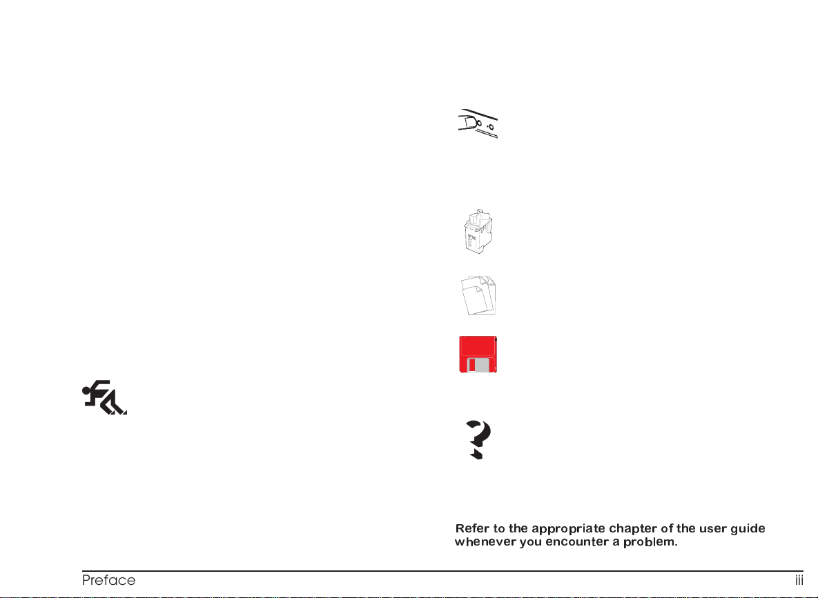
Preface
This manual is structured in several sections:
illustrations,
•
instructions, consisting of:
•
–aQuick Start,
–aUser Guide,
User Guide
User Interface
- Software printer monitor, indicating print job status and
containing a series of printer care functions.
- Printer operator panel, giving the functions of the light
indicators and keys.
- Templates, embossed on the printer casing, indicating
carriage movement, paper out condition and print head
insertion/removal procedures.
Ink Jet Print Heads
- How to insert/remove the ink jet print heads in/from the
printer, how to clean them and preserve optimum print
quality.
–aTroubleshooting Guide,
Glossary of terms, Appendices and an alphabetical
•
Index.
Quick Start
Unpacking and identifying the printer parts
Connecting your printer
Inserting the document supports
Loading paper
Inserting the print heads
Installing printer software
Preparing the printer using the printer monitor
Help
Troubleshooting Guide
Appendices
Refer to the appropriate chapter of the user guide
whenever you encounter a problem.
Paper
- Characteristics of the paper you can use in the printer.
- Use of document supports.
- Usable print area.
Using Software
- Description of the printing system interface and printer
monitor
- How to change the printer settings via the printer driver
settings or the printer set-up utility.
- Lists a series of common problemsand their solution.
- Indicates how to obtain the print test and hexdump.
Product characteristics, parameters and command codes.
Preface iii
Page 18

This Page Intentionally Blank
Page 19

Table of Contents
Preface
User Interface
PrinterMonitor.................. 11
Printer Operator Panel ............. 12
Quick Start
Unpacking..................... 1
IdentifyingthePrinterParts ........... 1
Connecting Your Printer ............. 1
InsertingtheDocumentSupports ........ 3
Loading Paper in the Printer ........... 4
InsertingthePrintHeads............. 4
InstallingPrinterSoftware ............ 5
Preparing your Printer using the Printer Monitor 9
Help........................10
EmbossedTemplates.............. 17
Ink Jet Print Heads
ReplacingthePrintHead............ 18
ReplacingtheInkCartridge........... 20
PhotoCartridge................. 21
Re-aligning the Print Heads .......... 21
PrintHeadCare................. 21
CleaningthePrintHead ............ 22
Paper
Types ...................... 23
Dimensions ................... 24
DocumentInsertion............... 24
PrintArea .................... 25
Table of Contents v
Page 20

Using Software
HowtoUseYourPrinterDriver.........28
PhotoKit .....................29
Appendices
A. Supplies
Running the Printer Set-Up Utility .......30
Troubleshooting
GeneralCare...................33
ProblemsandSolutions.............34
Installation ......................34
Paper......................... 35
Printheads......................37
Printing........................ 39
B. Command Code Su mmary
C. Programmable Printer Features
D. Product Characteristics
E. Getting Service and Support
F. Glossary
G. Index
vi Table of Contents
Page 21

Quick St art
Page 22

This Page Intentionally Blank
Page 23

Quick Start
This section is a rapid guide for installing your p rinter and
preparing it for use. It contains a sequence of operations
which should be
More detailed information about the printer features and
functions is given in the User Guide.
performed in the order described
.
The interface cable for connecting the printer to
your PC is NOT supplied with the printer.
1. Place the printer on an ample, stable surface
near your computer or work station.
2. Make sure that there is enough space around the printer
for all its parts to be accessed comfortably.
3. Make sure that there is a convenient independent
electrical power supply socket to which you can connect
the printer.
Unpacking
Keep the carton and all the packing materials in case
you have to repack or ship the printer.
4.
Do NOT leave the printer exposed to direct sunlight
or heat sources, or in dusty, dirty or poorly
ventilated environments.
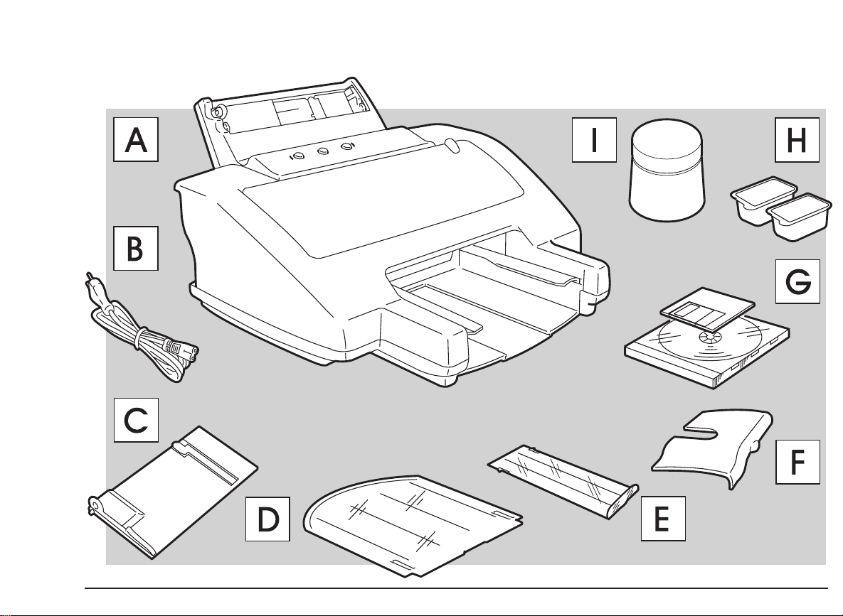
Carton contents
Identifying the Printer Parts
As well as this instructions manual and the NEC Media
Sample Pak, the packing carton also contains (
on page I
A - Printer B - Power cable
C - Manual feeder document support
D - ASF document support E - Output tray extension
F - Interface socket cover G - Diskette and CD
H - Ink jet print heads I - Print head storage box
As soon as you have removed the printer and its
accessories from the packing carton, check that all the
parts ordered have been delivered and are undamaged.
If anything is missing or damaged, contact your local
retailer immediately.
):
see figure
Quick Start 1
Take a few minutes to study your printer and identify its
parts. Refer to the figures in the first section of the manual.
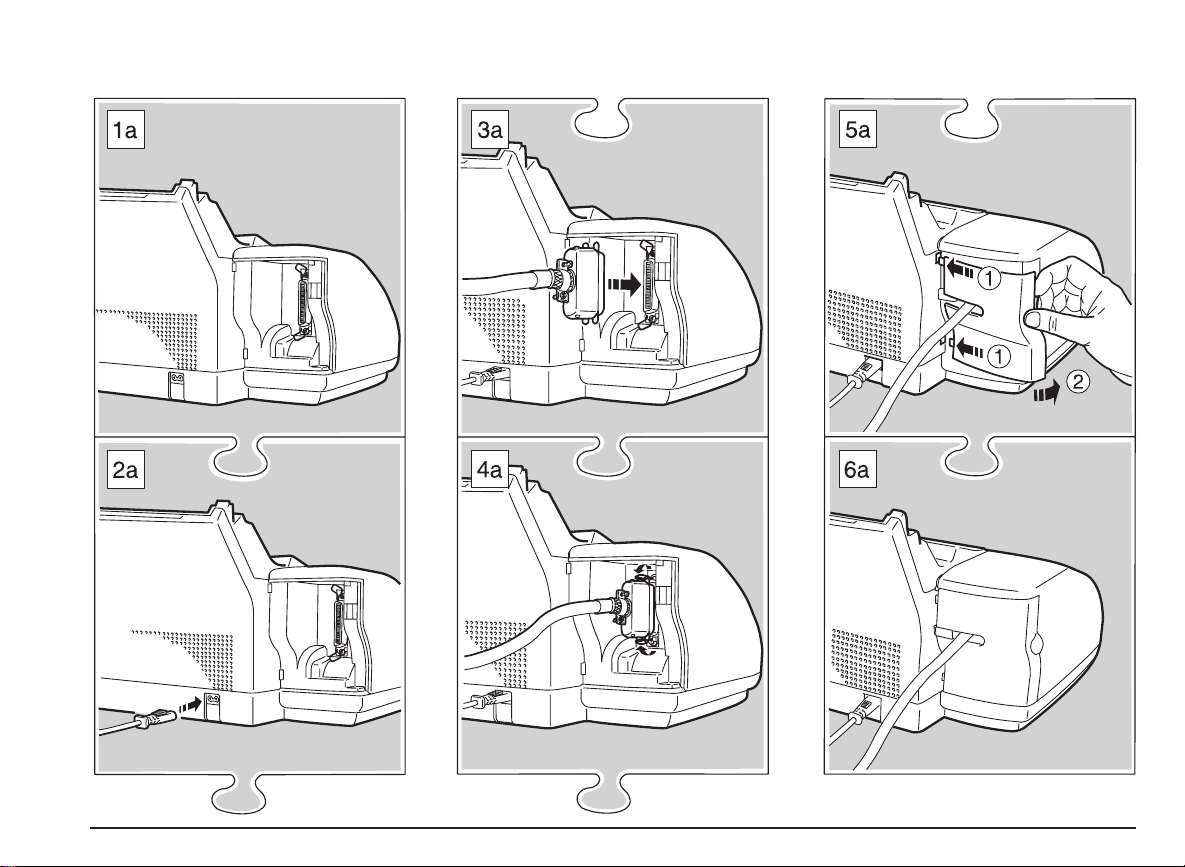
Connecting Your Printer
To the electrical power supply
Your printer has no
to the electrical power supply, it is powered by pressing
the
POWER
it is on a stable surface and that the cover is closed.
1. Insert the power cable in the two-pin connector on the
rear of the printer (
key on the operator panel, so make sure that
ON-OFF
see figure 2a on page II
switch; once it is connected
),
Page 24

2. Plug the printer power cable into a wall socket.
The socket outlet shall be installed near the equipment
and shall be easily accessible.
1.
The interface socket cover, which covers the parallel
interface cable, is in the accessories kit delivered in the
printer packaging.
Make sure the electrical power supplied has the voltage
indicated on the electrical data plate on the base of the
printer.
If the electrical dataplate indicates a different voltage, call
your local retailer immediately. DO NOT, UNDER ANY
CIRCUMSTANCES, CONNECT THE PRINTER TO THE
ELECTRICAL POWER SUPPLY.
Make sure that the plug on the power cable of the printer
is of the type accepted by the wall socket you intend to
use; if it is not, call your local retailer.
Do NOT attempt to change the plug yourself.
The manufacturer declines all responsibility for accidents
to persons or damage to the printer arising from the
non-observance of this warning.
To your computer
See figures 3a to 5a on page II.
The interface cable is not supplied with the printer;
consult your systems engineer or retailer for advice on
the type of cable you require.
Make sure that your computer/host system is switched
off and that the printer is not powered.
2. Plug the interface cable connector into the socket and, if
necessary, close the spring clips on it.
3. Mount the socket cover over the interface connector.
4. Connect the other end of the interface cable to the
appropriate interface connector socket (port) on your
computer/host system.
5. Press the POWER key on the printer operator panel and
switch on your computer.
The printer will take a few moments to execute a series
of internal checks. It will be in ON LINE condition (both
light indicators will be lit).
After approximately 2 minutes of inactivity, the
printer will go into “standby” mode. In standby
mode, the print head carriage returns to and remains
in its rest position at the right hand end of its path
and there is a reduction in the power consumption
(the light indicators on the operator panel remain lit).
To reactivate the printer, just send a file to be
printed or start any other printer operation.
2 Quick Start
Page 25

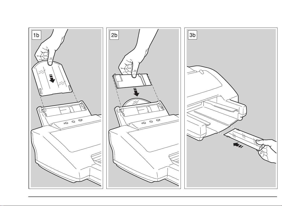
Inserting the Document Supports
Output tray extension (figure 3b)
See figures 1b, 2b and 3b on page III.
Remove the document supports from their packaging (which
should be kept, with the other packing material, in case you
need to repack your printer for relocation).
Document support for ASF (figure 1b)
With the rounded p art of the guide as the top edge, insert
the document support in the slot on the rear of the ASF so
that it slides into the casing.
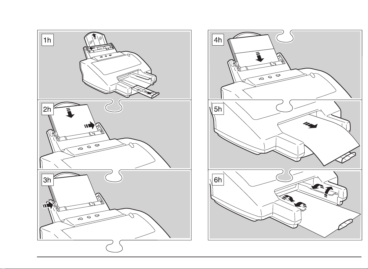
When using the ASF, pull the support upwards so that the
document format you intend to load is fully sustained (
figure 1h on pa ge IX
).
see
Document support for manual feed (figure 2b)
With the adjustable margin guide to the front left, insert the
document support in the front of the ASF so that it sits in the
grooves at the front and forms a second document insertion
channel.
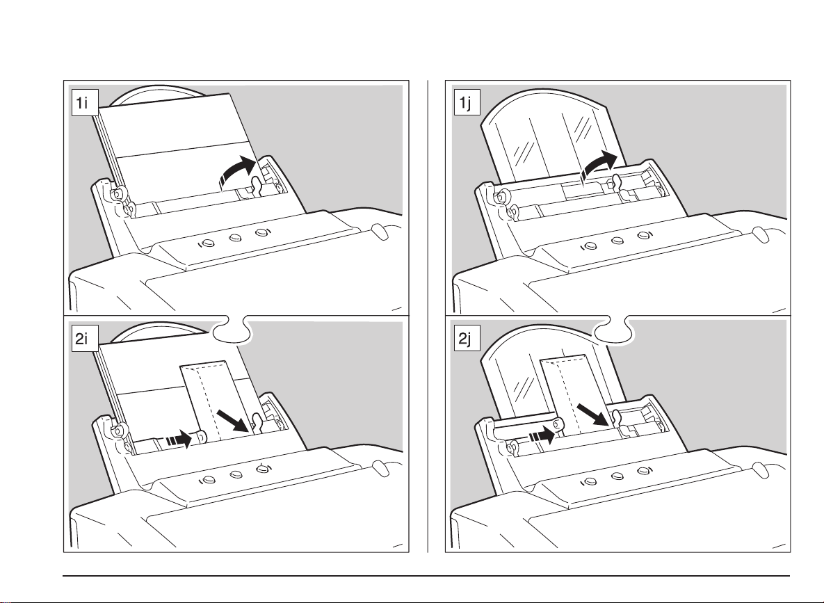
If you use narrow formats in the manual feed, you must
open and use the intermediate right margin (
on page X
).
see figure 1i
With the flat end towards the printer and the lip at the
opposite end facing u pwards, insert the tray extension
in the groove in the center of the output tray.
Before starting to print, pull out the extension so that the
tray accommodates the document format you are printing.
The indicator (LTR, A4, LEGAL) should be level with the
print casing (
seefigure1honpageIX
).
Quick Start 3
Page 26

Loading Paper in the Printer
Inserting the Print Heads
See the sequence of figures on page IX.
1. Holding the tab on the left edge of the guide on the ASF,
move it to its extreme left position (physical left hand
margin).
2. Fan the paper thoroughly.
3. Align the paper against the physical right hand margin
and load it into the ASF, pushing it down carefully until it
stops inside the printer.
The ASF can contain up to 120 x 21 lbs single sheets of
plain paper. For other types of documents and
envelopes, see “Paper” in the User Guide.
Do NOT add paper to that already in the ASF; always
remove any existing paper and fan it together with the
paper to be loaded.
4. Position the left guide against the left edge of the paper.
5. With the printer powered, press the PAPER key. A
sheet of paper is inserted to the first print position (TOF Top of Form). Press PAPER again, to make sure that
the paper feeds smoothly without crushing or skewing.
The paper will exit on to the output tray spoilers and will
drop into the tray when PAPER is pressed again to
load another sheet.
For further information on paper types, sizes, etc., see
“Paper” in the User Guide.
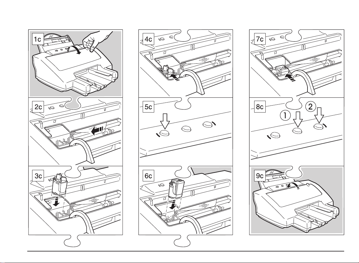
See the sequence of figures on page IV and the instructions on the inside of the cover (template on page XI).
The print head carriage on your printer is designed to hold
two print heads: monochrome black, on the left; color, on
the right.
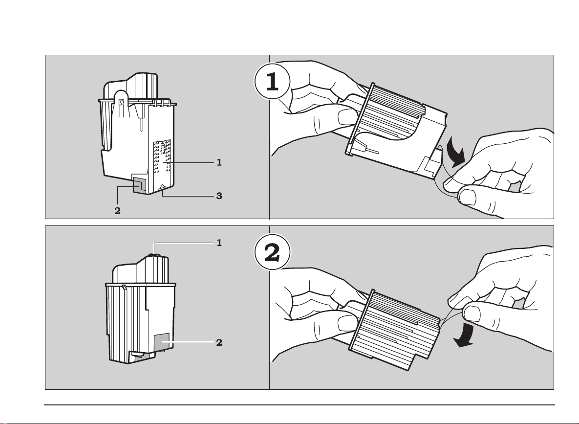
attempting any printing operation. To insert the print heads,
proceed as follows:
1. Make sure the printer is powered (if it is not, press the
2. Open the sealed print head container of the
3. Remove the print head from the container, holding it by
4. Remove the protective film from the print head (
BOTH
print heads
POWER key on the operator panel).
monochrome
leaflet (which should be kept for future reference).
the thumb and finger grip (end opposite the protective
film).
print head and remove the instructions
MUST
be inserted
BEFORE
point 2
in figure 1 on page VIII
).
Do not touch either the electrical contacts
(golden area - point 1 of figure 1 on page VIII) or
the printing nozzles (end opposite the finger/
thumb grip - point 3 of figure 1 on page VIII) nor
sit the print head on either of them.
5. Open the printer cover; the print head carriage will move
automatically to the head loading position for the
monochrome
light indicators will start flashing alternately.
print head (left hand chamber) and the
4 Quick Start
Page 27

6. With the electrical contacts (the golden area) of the print
head towards the corresponding contacts in the housing
on the print head carriage, insert the print head in its
chamber.
Installing Printer Software
Before installing your printer driver
7. Push the print head towards the rear of the printer to fix
it in place.
8. Press the ON LINE key; the print head carriage moves
to the left, to loading position for the
(right hand chamber).
9. Repeat points 2, 3, 4, 6, 7 of this section to insert the
color
print head.
10. To set the ink counter, press and hold PAPER and press
POWER for at least two seconds; the POWER light
indicator will flash three times to confirm that the counter
is set. A sheet of paper will be inserted automatically
and a nozzles test will be printed.
If the print head carriage returns automatically to its rest
position at the right hand side of the printer during the
print head insertion operation, just press the
key to bring it back to the head loading position.
11. Close the cover.
The print head carriage will return automatically to its
rest position, at the right hand side of the printer.
See “Ink Jet Print Heads” in the User Guide for further
details on the handling, substitution and care of the print
heads.
color
print head
ON LINE
The diskettes supplied with your printer contain a high
quality color and monochrome
Windows® 3.1/3.11 and Windows® 95 environments.
If you are installing using the CD, please follow the
instructions supplied with the NEC Media Sample Pak.
This advanced printing system includes :
a
printer driver
•
features through easy-to-use property sheets,
a
printer monitor
•
Printer Care.
A
printer set-up utility
settings under DOS if necessary, is also included in the
diskettes.
Before installing any printer driver, we strongly
recommend that you make a back-up copy of the original
diskettes (according to “Terms and conditions of the
user license” included with the diskettes) and then use
this copy for the installation procedure. This will allow
you to keep the original diskettes as masters so that,
should any problem arise with the back-up copy, you
can make another copy.
which gives you access to all the printer
for easy access to Printing Status and
printing system
program, for personalized printer
for both
Quick Start 5
Page 28
q
Informationfile(README.TXT)
PrinterDriverInstallationProcedure
Whenevernecessary,latestinformationontheprinter
driver,orinstructionsupdatingthismanualareincludedin
aninformationfilecontainedinthediskette(s).Ifpresent,
thefilewillautomaticallybecopiedintothedrivergroupthat
willbecreatedduringdriverinstallation.
Ifyouwanttocheckthisfiledirectlyfromthediskette,you
willfinditineachlanguagedirectory:
underWindows®3.1/3.11,openitthroughthe“Write”
•
application.
underWindows®95,openitthroughthe“Wordpad”
•
application,specifyingthecorrectfileextension(*.TXT)
q
Systemrequirements
FromWindows®3.1uptoWindows®95,
•
PC386orlaterwithatleast4MBytesofRAM(8Mbytes
•
recommendedforWindows®95),
1MByteoffreediskspace.
•
Theinstallationprocedurewillvary,dependingonthe
Windows®environmentinstalledonyourPC.
q
Windows®3.1/3.11
1.StartMicrosoftWindows®.
(Ifitisalreadyrunning,makesurethatallWindows
applicationtasksareclosedbeforestartingtoinstallthe
driver.)
2.InsertthedriverdisketteindriveA(orB)ofyourPC.
3.FromtheFilemenuoftheProgramManager,selectthe
option“Run...”.
4.TypeA:\SETUP.EXE(orB:)andpressENTER.
Theinstallationprocessstarts.
5.Followtheinstructionsgiveninthesequenceofwindows
displayedonyourPCscreen,untilthedriverisinstalled.
6.Agroupwindowwiththedrivernamewillbecreated
automatically.ItallowsimmediateaccesstotheSpool
Manager,thePrinterMonitor,theHelpandinformation
fileswheneverthesearerequired.
Youcanalsoinstalltheprinterdriverthroughthe“Add
Printer”featureintheControlPanelinProgram
Manager/Main,proceedingasfollows:
1.InsertthedisketteindriveA(usually)ofyourPC.
2.ActivateMicrosoftWindows®environment(Ifitis
alreadyrunning,makesurethatallWindowsapplication
tasksareclosedbeforestartingtoinstallthedriver.)
6 QuickStart
Page 29
3. Activate the Control Panel in the Main window, clicking
twice with your mouse indicator on the corresponding
icon.
4. Select the Printers icon, in the same way.
5. If the Installed Printers box is empty, click on Install..
6. If the Installed Printers box already contains one or
more driver names, click on Add>> , select Install
Unlisted or Updated Printer in the List of Printers and
then click on Install... .
7. Check that the Install Driver window already indicates
the drive (usually A) in which you have inserted the
driver diskette, otherwise, click on the drive name and
change it, using your PC keyboard; click on OK.
8. The Add Unlisted or Updated Printer window contains
the list of drivers present on the diskette. Select the
driver with your printer name and click on OK.
9. Your driver is now installed and your printer name
appears in the List of Printers.
10. With your printer name highlighted, click on the Set as
Default Printer button, so that your printer will be active
in all your Windows® applications.
11. Check your printer connection by clicking on the
Connect.. button.
By default, your printer will be connected on the LPT1
port which corresponds to the hardware connection of a
parallel interface cable.
12. Click on the Close button of the Printers dialogue box.
q
Windows® 95
The Microsoft Windows® 95 operating system allows
automatic installation of peripherals through the
“Plug & Play” feature, a bi-directional communication and
hardware recognition procedure.
1. Make sure that both printer and PC are powered.
The printer must NOT be in error mode, i.e. the
indicator lights must not be flashing.
2. Activate Microsoft Windows® 95. If already started,
execute the “Shut down” command and restart the
computer.
3. A window opens, indicating that a new peripheral has
been detected (New Hardware found and the printer
name).
The same window shows the Driver from disk
provided by hardware manufacturer option already
highlighted. Click the OK button.
4. With the Install from Disk window displayed, insert the
printer driver diskette in the drive selected, specify this
drive if requested and click OK.
5. The Add Printer Wizard window is displayed.
If there are no other printer drivers already installed on
your system, your printer will be installed as the Default
printer.
If other printer drivers are already installed, and you
wish to install the current one as the default printer, click
Yes and then the Finish button.
The installation of the driver files will start.
Quick Start 7
Page 30
6. At the end of the installation, you will be asked to
remove the diskette and restart Windows.
change the setting in your system properties, as
follows:
A folder with the driver name will be cr eated automatically in
the Programs folder. It allows easy
access at any time to the Printer Monitor, the Help and
information files whenever these are required.
You can also install your driver through the Add Printers
procedure. In this case, your printer need not be connected
to your PC.
Do not install with the set up program.
1. Click Start, highlight Settings, and then click Printers in
the sub-menu which opens.
2. Double click Add Printer in the Printers window.
3. The first in a series of Add Printer Wizard windows is
displayed; click Next > .
4. Click Have Disk... in the window now displayed.
5. Insert driver diskette no. 1 in drive A (or B)ofyourPC;
click OK.
6. Click Next > .
7. Make sure LPT1: Printer port is highlighted;
click Next > .
If you have an “ECP” computer, make sure that the
port setting for the printer is set to Printer Port
(LPTx) and not to ECP Printer Port (LPTx). If
necessary, once the driver installation is completed,
– right click on the My Computer icon,
– select Properties, then Device Manager,
– double click on Ports (COM&LPT),
– select Printer Port: LPTx.:
8. Click Finish.
The installation of the driver files will start.
9. At the end of the installation, you will be asked to
remove the diskette and restart Windows.
For more details on the printer driver, its parameters and
the printer set-up, see “User Interface” and “Using
Software” in the User Guide or consult your Windows®
documentation.
8 Quick Start
Page 31

Preparing your Printer using the Printer
Monitor
Your printing system, i.e. the
monitor
system, you must prepare your printer by performing two of
the Printer Care functions contained in the P rinter Monitor:
1. check the print accuracy (Align),
2. print a demo page (Demo).
is now installed. Before using your printing
printer driver
and the
printer
3. Click your right mouse button.
4. Select the option “Run the Printer Monitor”in
the menu which opens.
In both environments, the Printer Monitor will also be
activated any time a print job is sent (in Windows® 95, the
option “Show Monitor during Print” has to be already
selected).
Use of the Printer Monitor
How to access the Printer Monitor
q
Under Windows® 3.1/3.11:
The Printer Monitor can be accessed from your printer
group at any time: just double-click the specific icon.
q
Under Windows® 95:
The Printer Monitor can be accessed at any time in either of
the following ways:
1. Click Start, highlight Programs and then the printer
name in the sub-menu which opens.
2. Click the Printer Monitor icon.
OR:
1. Click Start, highlight Settings, and then click Printers in
the sub-menu which opens.
2. Click your printer name to highlight it.
The Printer Monitor contains two tabs:
Status : which provides information on the file printing job,
as well as on job and page printing progress.
Printer Care : which allows you to run four different
“service” operations:
Align : print head alignment (checking print accuracy),
•
Clean : print head cleaning,
•
Demo : printing of the “demo” page,
•
Test : printing of the printer test page.
•
If you leave your Printer Monitor active, the status of your
print jobs will always be displayed automatically.
Quick Start 9
Page 32

Checking print accuracy (Align)
Help
Whenever you insert a new print head or ink cartridge, you
should always check the horizontal and vertical
printing accuracy, to guarantee optimum printing quality.
The Printer Monitor in your printing system makes this
operation extremely easy:
Make sure your printer and PC are powered, your
printing system is installed, both print heads are
inserted and paper is loaded.
1. Open the Printer Monitor on your PC screen.
2. Click the Printer Care tab.
3. Click the Align button, then follow the instructions
displayed.
Printing the “demo” page (Demo)
The demo page gives you a full color and black
monochrome print-out and allows you to check the correct
functioning of the print heads.
1. Check that you are still in the Printer Care tab of the
Printer Monitor.
2. Click the Demo button, then follow the instructions
displayed.
To simplify the use of the printer, and to help you if you
have problems, this printer has an extensive user interface:
from your PC screen; the printing system installed from
•
the diskette supplied contains a printer driver and Printer
Monitor with user-friendly screen interfaces and a
detailed Help file.
For further details, see “User Interface” and “Using
Software” in the User Guide.
the flashing of one or both of the light indicators on the
•
printer operator panel signals the need for operator
intervention.
For further details, see “Operator Panel” in the User
Guide.
two embossed templates (
•
on the printer casing under the cover, the other on the
inside of the cover, illustrate certain operating
procedures.
For further details, see “Embossed Templates” in
the User Guide.
Your printer is now ready for use. If you have problems
with any operating procedure, or are unable to perform a
specific function, always check that you have followed
the instructions as given. If a repetition of the
instructions is unsuccessful, see “Problems and
Solutions” in the User Guide.
see figures on page XI
), one
Once you have completed these two operations, you can
close the Printer Monitor.
10 Quick Start
Page 33

User Guid e
Page 34

This Page Intentionally Blank
Page 35

User Interface
This section describes the user interface of your printer, i.e.
those parts and features that you use and/or refer to during
the day-to-day use of the printer. The user interface
comprises the Printer Monitor which is loaded in your PC
when you install your printing system, the printer operator
panel and the templates embossed on the printer casing.
Checking print accuracy (Align)
Whenever you insert a new print head, you should
check the accuracy of bi-directional printing, to
guarantee optimum printing quality. The Printer Monitor in
your printing system makes this operation extremely easy:
Make sure that your printer and PC are powered, your
printing system is installed, both print heads are
inserted and paper is loaded.
1. Click the Printer Monitor icon.
Printer Monitor
The Printer Monitor is an on-screen aid containing a series
of functions which help you during daily use of the printer. It
is displayed by clicking on the specific icon.
The Printer Monitor allows you to:
view the printer operating status during a print job. It
•
indicates the proportion of the document printed and
eventual error messages (Stat us),
perform printer care functions, to maintain optimum
•
workingconditions (Printer Care):
– Align : print head alignment (checking accuracy of
bi-directional printing),
– Clean : print head cleaning,
– Demo : printing of the “demo” page,
– Test : printing of the printer test page.
2. Click the Printer Care tab.
3. Click the Align button, then follow the instructions
displayed.
Cleaning the print heads (Clean)
If you notice a deterioration in the print quality, before
changing either/both print heads, run the “Clean” function.
1. Click the Printer Monitor icon (if necessary).
2. Click the Printer Care tab.
3. Click the Clean button, then follow the instructions
displayed.
User Interface - Printer Monitor 11
Page 36

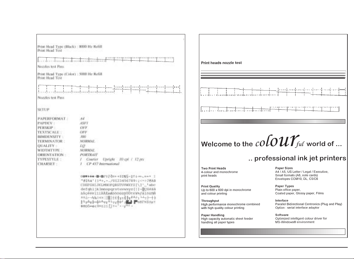
Printing the “demo” page (Demo)
Printer Operator Panel
Thedemopage(
color/black monochrome print-out and allows you to check
the correct functioning of the print heads.
1. Click the Printer Monitor icon (if necessary).
2. Click the Printer Care tab.
3. Click the Demo button, then follow the instructions
displayed.
see example on page XI
) gives you a full
Running the print test (Test)
The print test (
print-out of the printer functional characteristics (firmware
release, print head test, current settings).
1. Click the Printer Monitor icon (if necessary).
2. Click the Printer Care tab.
3. Click the Test button, then follow the instructions
displayed.
The Printer Monitor has an extensive, user-friendly HELP
feature which explains all its functions.
see example on page XI
) gives you a
The behavior of the keys and light indicators on the operator
panel will depend on the printer’s status and whether the
front cover is closed or open.
Printer states:
free: no data to be printed;
•
busy: from the reception of data until the completion of
•
its printing;
standby: printer powered but dormant (more than two
•
minutes have elapsed since last interchange with host);
reduces power consumption.
special function mode : user-invoked operating mode
•
independent of host.
12 User Interface - Printer Operator Panel
Page 37

Basic key functions
Function Key Description
Printer ready/
Pause
Paper load/
eject
ON LINE Toggles the printer ON/OFF LINE
condition.
When the printer is ON LINE, the
ON LINE light indicator is lit and
the printer can process and print
data recei ved from your computer.
When the printer is OFF LINE
(pause), the print head carriage
returns to its rest position at the
physical right margin. The ON
LINE light indicator is off and any
printing operation is suspended.
PAPER With paper loaded in the ASF, but
none already inserted for printing,
loads a sheet of paper to the first
print position.
With paper already inserted for
printing, expels it on to the
spoilers above the output tray.
Pressing again PAPER will open
the spoilers so that the paper on
them falls into the output tray and,
simultaneously, another sheet will
be inserted from the ASF for
printing.
Function Key Description
Printer ON/OFF POWER Toggles the printer POWER
ON/OFF condition.
When the printer is powered,, the
POWER light indicator is lit.
Also has the printer RESET
function.
User Interface - Printer Operator Panel 13
Page 38

Special key functions
q
with printer cover CLOSED
Function Key(s) Description
“Demo” page Press and hold PAPER
Print test
first page only
complete
Clean print
head
and press POWER for
at least 2 seconds.
Press and hold in this
order: ON LINE, then
PAPER,thenPOWER.
Hold all three keys until
both light indicators go
off, then release them
together:
press ON LINE three
times.
press ON LINE,
POWER, ON LINE,in
this order.
Press and hold
ON LINE and press
PAPER for at least 2
seconds.
The “demo” page is
printed; after which the
printer returns ON LINE.
Access to special
functions mode.
The first page of the
print test is printed.
This page contains the
printer release level,
the nozzles test, the
currently selected
parameter values and
character set.
The complete print test
is printed.
The pages following the
first contain the internal
fonts available.
The printer executes a
head cleaning
operation on both print
heads.
Function Key(s) Description
Hex dump Press and hold in this
Exit from hex
dump
order: ON LINE, then
PAPER,thenPOWER.
Hold all three keys until
both light indicators go
off, then release them
together; then press
ON LINE, PAPER,
POWER, in this order.
POWER Printer switched off.
All subsequent data
transmitted to the
printer will be printed in
its hexadecimal format.
This feature should be
used only under
technical guidance,
as it can generate
extremely long
print-outs; see
Troubleshooting
Guide.
14 User Interface - Printer Operator Panel
Page 39

Special key functions
q
with printer cover OPEN
Function Key(s) Description
Print head
carriage
movement
Reset counter Press and hold
ON LINE Toggles the monochrome/
PAPER and
press POWER
for at least
2 seconds
color print head change
position.
Resets the ink counter.
Re-activates the “end of
ink” signal when you
replace the print head or
the ink cartridge.
The POWER light indicator
flashes three times.
User Interface - Printer Operator Panel 15
Page 40

Light indicator functions
Light Indicators
Meaning
ON LINE POWER
lit lit The printer is powered and either ON
LINE, or in standby mode (dormant),
i.e. within the last two minutes, there
has been no printer- host activity nor
operator action.
To return the printer to its operating
condition, just send a file to be printed
or start any other operation.
off lit The printer is powered and OFF LINE.
flashing alternately 1. No print head installed.
2. “End of ink” condition on one of
the print heads.
When you open the printer cover, the
print head carriage will move so that
the print head which caused the error
signal is in the loading position.
If there is no operator intervention
within 40 seconds of the error being
signaled, the print head carriage will
return to its rest position. To return the
print head carriage to the loading
position, press ON LINE or close and
re-open the printercover.
Light Indicators
ON LINE POWER
off single,
flashing
slowly
three-flash
sequence
off 1. If, after a print head replacement
Meaning
Ink counter has been reset correctly
following the replacement of a print
head/ink cartridge and the pressing of
PAPER and POWER for at least 2
seconds.
operation, the print head carriage
remains in the loading position,
the print head has not been
inserted correctly.
Make sure the print head is inserted
in the correct position and blocked
correctly. If it is not, repeat the
insertion operation, pushing the
head towards the rear of the printer
to fix it in position and then press
ON LINE.
2. “Paper out” condition on reception
of data to be printed.
If you open the printer cover, the
print head carriage will be positioned under the “paper” template.
Load paper in the ASF or insert a
single sheet in the manual feeder
and press PAPER.
16 User Interface - Printer Operator Panel
Page 41

Light Indicators
ON LINE POWER
flashing
intermittently
flashing rapidly Failure condition.
off Paper jam or spoilers blocked.
Switch off the printer, open the cover
and remove the jammed paper. Close
the cover and re-power the printer.
If the light indicator continues flashing
intermittently, disconnect the printer
and call the technical support service
or your dealer.
Disconnect the printer from the
electrical power supply. Make sure the
print head carriage and paper feed
paths are not obstructed and then
reconnect the printer to the electrical
power supply and press POWER.
If the light indicators continue flashing
rapidly, disconnect the printer and call
the technical support service or your
dealer.
Meaning
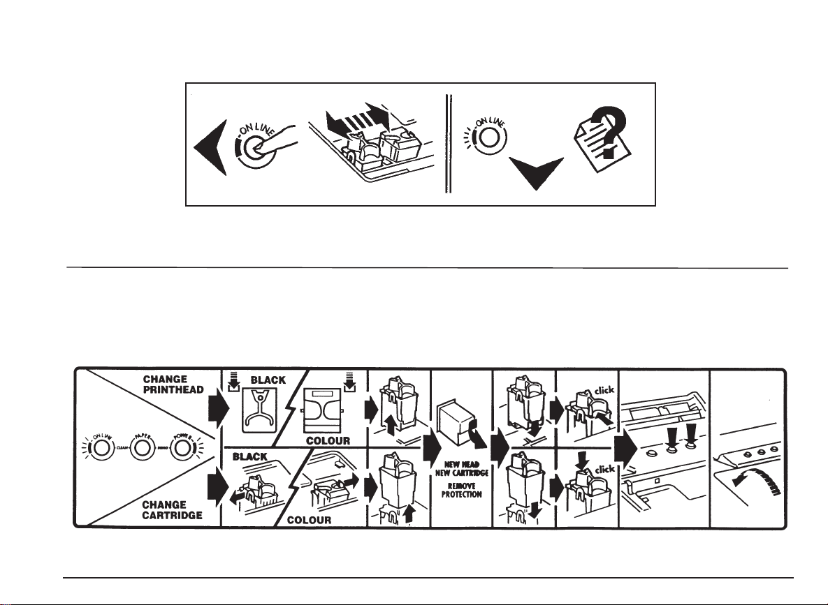
Embossed Templates
See figures on page XII.
Your printer has two embossed instruction templates: one
on the printer casing under the cover, the other on the
inside of the cover:
q
on the printer casing under the cover
how to move from one print head replacement position
•
to the other;
the print head carriage position if a “paper out” condition
•
occurs.
q
ontheinsideofthecover
the operating procedure for changing the print heads.
•
For further details see “Ink Jet Print Heads” and the
appropriate sections in the Troubleshooting Guide.
off 1. The printer is in special functions
mode, awaiting a key sequence to
activate a specific function.
2. The printer is not powered.
User Interface - Embossed Templates 17
Page 42

Ink Jet Print Heads
Your printer is a full-color printer. It must be equipped with
both its monochrome and color print heads in order to
operate correctly.
The
print heads with replaceable ink cartridges
with the printer have an outer casing, with the nozzles and
the electrical contacts, and an ink cartridge which fits inside
the outer casing. This economical and ecological system
allows you to change the cartridge several times before you
have to change the entire print head. This type of print head
generates an “end of ink” condition when the ink runs out,
causing printing to stop, the light indicators to flash
alternately and an error message to be displayed on your
PC screen.
The printer also supports a
print head and ink cartridge which you can use with the
specific driver supplied to print photographic images.
ALWAYS use manufacturer-original Ink Jet Print Heads
and Cartridges.
This section describes:
how to replace the print heads and the ink cartridges,
•
how to clean the print head,
•
how to preserve optimum print quality.
•
Photo Cartridge
supplied
: an all-in-one
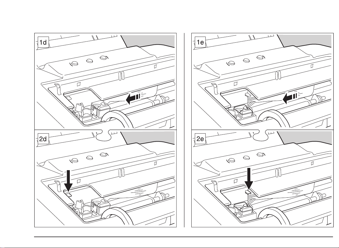
Replacing the Print Head
See figures 1d and 2d on page V, for the monochrome
print head and 1e and 2e on the same page for the color
print head/Photo Cartridge, and the indications on the
template on the inside of the cover.
You should remove the print head from the printer
replace it or to repeat its insertion ( see
Head
in the Quick Start), in the case of faulty printing.
When replacing the print head, take care not to touch the
print head carriage shaft nor the area under the print
head carriage.
Any document inserted for printing will be expelled if
you remove the color print head.
To remove the print head, proceed as follows:
1. Open the printer cover;
(a)
print head with replaceable ink cartridge only:
if you are changing the print head due to an “end of ink”
condition signaled by the printer (printing stopped, both
ON LINE and POWER light indicators on the printer
operator panel flashing alternately, and an error
message on your PC screen), the print head carriage
will move automatically to the head loading/ replacement
position of the print head which caused the error signal.
(b)
all types of print heads:
if you are changing the print head due to deteriorated
print quality which has NOT been signaled by the printer
(
you pressed
opening the cover
the monochrome print head loading/replacement
ON LINE
to interrupt printing BEFORE
), the print head carriage will move to
Inserting the Print
only
to
18 Ink Jet Print Heads - Replacing the Print Head
Page 43

position. If you wish to change the color print head, you
must press ON LINE to move the print carriage to the
correct loading/ replacement position.
If you do nothing within the next 40 seconds, the print
head carriage returns to its rest position. To return to
the replacement position, press
2. Press down the green print head release lever (left for
monochrome print head; right for color print head) to
release the print head.
3. Remove the print head, pulling it upwards by the thumb
and finger grip.
4. Insert a new print head in its place.
The print head carriage will accept ONLY
monochrome print heads in the left chamber, and
color/Photo cartridge;positionPhoto Kit print heads
in the right.
If you insert a print head in the wrong chamber, the
print head carriage will not return to its rest position
and the light indicators will continue to flash.
For the description of the print head insertion procedure,
see
Inserting the Print Heads
5. Only if you have inserted a NEW print head or
replaceable ink cartridge,
COVER
at least two seconds to reset the ink counter.
The POWER light indicator will flash three times to
confirm that the counter is reset and a sheet of paper will
be inserted automatically and a nozzles test printed.
, press and hold PAPER and press POWER for
ON LINE
in the Quick Start.
BEFORE CLOSING THE
.
6.
If you pressed
cover, you must press it again after closing the
cover, to return the printer to its operating status.
If, after replacing a print head, the print head carriage
remains in the loading position and the
indicator is flashing slowly, the print head has not been
inserted correctly or is in the wrong position.
Make sure the print head is inserted in the correct
chamber (black, left; color, right) and fixed correctly,
pushing it towards the rear of the printer to fix it in
position and then press
If you have problems inserting a print head:
Make sure you are loading the print head in the correct
•
chamber on the print head carriage.
Check that the print head chamber is clean and free of
•
foreign bodies.
NEVER force the print head into the chamber. Always
•
remove it completely and repeat the entire insertion
operation.
For other problems, see the specific items in the
Troubleshooting Guide.
ON LINE
ON LINE
before opening the
ON LINE
.
light
If you are re-inserting a color/Photo Cartridge print head
from the print head storage container, you MUST NOT
reset the ink counter.
Ink Jet Print Heads - Replacing the Print Head 19
Page 44

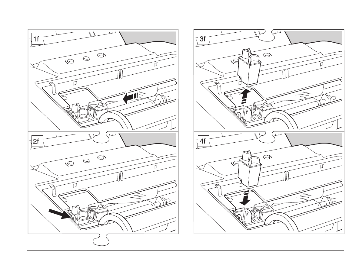
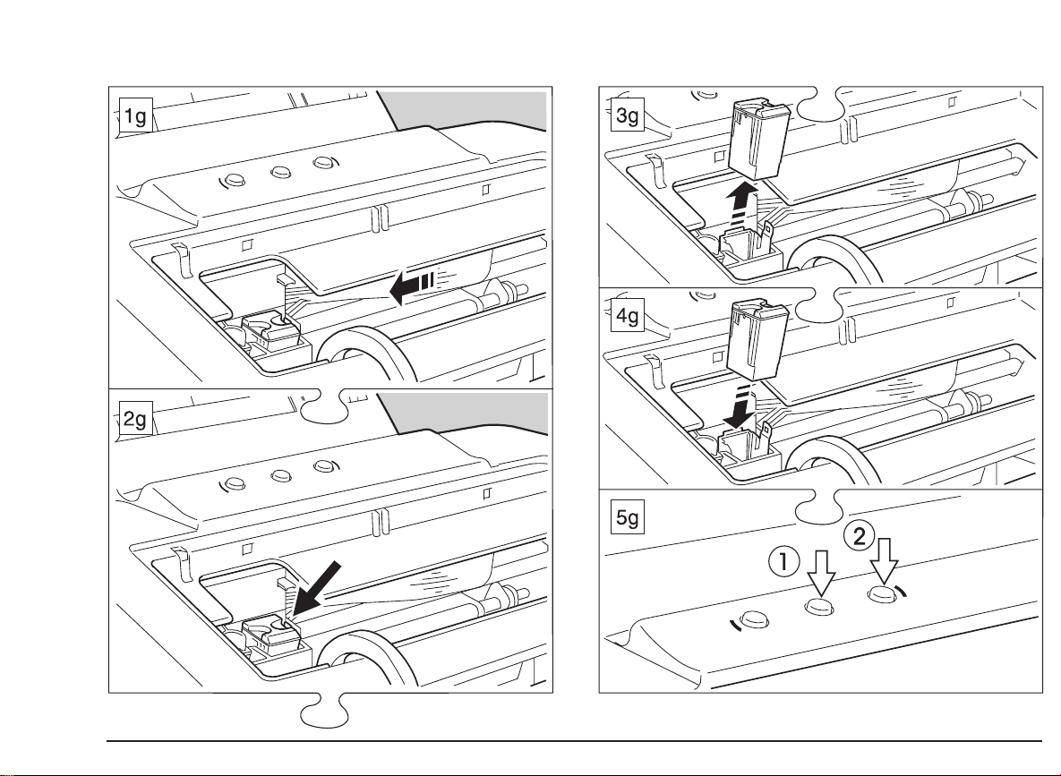
Replacing the Ink Cartridge
See the sequence of figures on page VI (1f to 4f) for the
monochrome print head and on page VII (1g to 5g) for
the color print head and also the indications on the
template on the inside of the cover.
When replacing the ink cartridge, take care not to touch
the print head carriage shaft nor the area under the print
head carriage.
Any document inserted for printing will be expelled if
you remove the color ink cartridge.
When the ink cartridge in either of the print heads runs out
of ink, an “end of ink” condition is signaled: printing stops,
both ON LINE and POWER light indicators on the printer
operator panel start flashing alternately and an error
message is displayed on your PC screen.
To substitute the empty ink cartridge:
1. Open the printer cover.
The print head carriage will move automatically to the
head loading/replacement position of the empty print
head.
If you do nothing within the next 40 seconds, the print
head carriage returns to its rest position. To return to
the loading/replacement position, press
2. Release ONLY the ink cartridge from the print head
casing, pulling gently outwards the lateral lip on the print
head casing;donot
release or remove the print head
casing from its chamber in the printer.
ON LINE.
4. Open the sealed ink cartridge container and remove the
instructions leaflet (which should be kept for future
reference).
5. Remove the ink cartridge from the container, holding it
by the thumb and finger grip.
6. Remove the protective tape/capsule from the new ink
cartridge.
Do NOT touch the ink pad area on the cartridge.
7. Insert the new cartridge in the print head casing
immediately, pressing in until it clicks into place.
8.
BEFORE CLOSING THE COVER
PAPER and press POWER for at least two seconds to
reset the ink counter.
The POWER light indicator will flash three times to
confirm that the counter is reset and a sheet of paper will
be inserted automatically and a nozzles test printed.
9. Close the printer cover.
, press and hold
If your printing operation was interrupted, it will now
resume automatically from the point at which it stopped.
If you have not inserted the new ink cartridge correctly,
the light indicators on the operator panel will continue to
flash. You must repeat the entire replacement operation.
If the quality of printing is not optimum, try cleaning the
print head (see Print Head Care in this section).
3. Remove the cartridge from the print head casing, pulling
it upwards.
After replacing the ink cartridge several times, you must
replace the entire print head (complete with outer casing).
20 Ink Jet Print Heads - Replacing the Ink Cartridge
Page 45

Photo Cartridge
Print Head Care
This all-in-one print head has been developed especially for
printing photographic images. It contains water-resistant
three-color and Photo Black ink.
You should inserted the Photo Cartridge in place of the
color print head, which you must keep in the storage
container provided.
See “Paper” and “Using Software” for information on the
types of printing media to use and the installation of the
specific Photo Kit driver.
Re-aligning the Print Heads
Whenever you change the print heads, you must check their
alignment.
This operation can be done either using the Printer Monitor
in Windows® environment or the printer setup utility
program under DOS.
See the specific sections in “Quick Start” and “Using
Software”.
Always keep the print heads and ink cartridges
sealed until they are to be used.
Separate the ink cartridge from the print head ONLY to
replace it. Do NOT remove and then reinsert it. The ink
cartridge replacement operation should done ONLY
when a new cartridge is available for IMMEDIATE
substitution; the print head MUST NOT be left without an
ink cartridge inserted.
Remember to remove the protective tape/capsule (point
2 in figure 2 on page VIII) before inserting the print
head/ink cartridge in the printer. Take care not to get ink
on your clothes; the ink in the cartridge stains.
Do NOT remove the cap (point 1 in figure 2 on page VIII)
from or attempt to refill a cartridge with ink, as this
damages the print head and the printer.
DO NOT shake the print head; it is not a fountain pen. If
it does not print, do the cleaning operations described in
the next section.
If you think that the number of pages printed with the
current print head/cartridge is fewer than usual, try
cleaning the print head. If the “end of ink” condition
persists, the print head/ink cartridge is empty and
requires replacing.
Always press
from the power supply or before switching off your
computer. This will guarantee that the print head
carriage returns to its rest position.
POWER
before disconnecting your printer
Ink Jet Print Heads - Photo Cartridge 21
Page 46

When the printer is powered, the print head carriage will
automatically return to its rest position after 40 seconds
of inactivity.
Cleaning the Print Head
The print heads are cleaned a utomatically at regular
intervals while the printer is powered. This operation
clears the print head nozzles, guaranteeing the ink flow.
If you have a problem with the printing quality that is not
solved by this automatic nozzle clearing operation, you can
do the same operation, using:
a key combination:
•
WITH THE PRINTER COVER CLOSED
ON LINE,pressPAPER for at least two seconds and
then release both keys together.
the “CLEAN” function in the print care tab in the Printer
•
Monitor (see the specific section in
If you have a problem with the printing quality that is not
solved by the nozzle clearing operation described above, try
cleaning the print head, as follows:
1. Open the cover, release and remove the print head.
2. Clean the electrical contacts (gold part) on the print head
and in the housing on the print head carriage with a
slightly damp lint-free cloth, taking care not to touch the
print head nozzles.
, press and hold
User Interface
).
If there is still no improvement in the p rint quality, try
cleaning the print head nozzles.
This operation MUST NOT be repeated systematically, as
it can damage the print head. It should ONLY be
attempted as a last resort, before changing the ENTIRE
print head.
1. Open the cover, release and remove the print head.
2. Dampen a tissue handkerchief with distilled water;
squeeze it slightly to remove any excess water.
3. Holding the print head with its nozzles facing
downwards
lightly.
4. Repeat the blotting operation a few times on different
areas of the handkerchief, to clean the nozzles.
5. Reinsert the print head in the printer and print the
“demo” page to check the quality of printing (see the
specific section in the
For other problems, see the specific items in the
Troubleshooting Guide.
, blot it against the handkerchief, pressing
Quick Start
).
3. Re-insert the print head in the printer and close the
cover.
22 Ink Jet Print Heads - Cleaning the Print Head
Page 47
Paper
When inserting the sheets for printing, make sure
that the printing surface is face the correct way
(see the instructions on the paper packaging or
container).
This section contains information on the various types of
documents you can use in your printer.
Types
q
Plain paper
Best results are obtained using good quality plain office
paper with a weight between 15 and 30 lbs. Using 21 lbs
paper, you can load a pack of up to 120 single sheets in the
ASF.
q
Special printing media (high resolution coated/glossy
paper, transparencies, T-Shirt transfers)
When you require top professional printing quality, e.g. for
presentation documents in color and for all types of
illustrations (photograph reproductions, drawings and
graphics), you should always use media specifically
indicated for ink jet printers.
Best results are obtained with 24 to 28 lbs documents. You
should use recommended media types (see “
ask your dealer if you require further information. Using
24 lbs documents, you can load up to 40 pieces (max. total
thickness: 6 mm) at a time in the ASF .
Supplies
”) and
The drying time for the ink on the special printing media is
somewhat longer than for plain paper. Always remove the
printed page as soon as it exits from the printer and set it
aside to dry thorougly before handling it. Do NOT stack
such pages.
q
Envelopes
Best results are obtained using quality bond envelopes with
a weight between 19 to 25 lbs. Using 21 lbs envelopes, you
can load up to 25 at a time in the ASF.
q
Note cards
Best results are obtained using note cards with a weight
between 25 to 35 lbs. Using 25 to 28 lbs note cards, you
can load up to 10 at a time.
Paper - Types 23
Page 48

Dimensions
Document Insertion
The following table indicates the document formats you can
use in your printer:
Single Sheets
(width x length)
A4 210 x 297 mm
A5
(vertical)
Letter 8.5 x 11 in
Legal 8.5 x 14 in
Executive 7.25 x 10.5 in
8.26 x 11.7 in
148.5 x 210 mm
5.85 x 8.26 in
215.9 x 279.4 mm
215.9 x 355.6 mm
184.2 x 266.7 mm
COM-10 4.125 x 9.5 in
DL 110 x 220 mm
C5 162 x 228 mm
C6 114 x 162 mm
B6 125 x 176 mm
Envelopes
(width x length)
104.7 x 241.3 mm
4.33 x 8.66 mm
6.37 x 9 in
4.4 x 6.27 in
4.92 x 6.92 in
Note cards (width x length)
#1 4x6in
#2 5x8in
A6 105 x 148.5 mm
T-Shirt transfers
You can insert all document formats both in packs through
the ASF or manually, one at a time, through the manual
feeder. A single document in the manual feeder will have
insertion priority over the document(s) in the ASF.
The documents, including small formats such as A5, note
cards and envelopes, should always be inserted with their
shorter side as the leading edge.
For document insertion in the ASF,
see figures 1h to 6h on
pageIXandthedescriptionintheQuickStart.
Envelopes, glossy, coated, transparencies and T-Shirt
transfers should be inserted with their printing side face up
and envelopes must have the sealing flap underneath.
When using envelopes, remember to select a landscape
font for printing. When using as type of special printing
media, always select the appropriate printing feature (Photo,
Art, etc.) When using T-Shirt transfers, remember to select
the reverse printing feature (“Mirror”).
q
in the ASF
The paper pack must not exceed 12 mm (0.45 in) for
•
standard plain paper and envelopes, (approximately
120 single sheets or 25 envelopes) and 6 mm (0.23 in)
for all other types of printing media.
If you use a narrow document format (less 165 mm (6.5
•
in) wide) or any type of envel ope, you must use the
intermediate right hand margin guide , opening it
outwards (
see figures 1j and 2j on page X
)before
inserting the document to be printed.
24 Paper - Dimensions
Page 49

If you load a pack of envelopes or narrow documents,
•
you cannot then insert a wider format using the manual
feeder.
q
in the manual feeder
A single document in the manual feeder w ill have insertion
priority over the document(s) in the ASF.
Print Area
The following tables contain the measurements of
the physical print area on the document and envelope sizes
handled by the printer. The printer can print a maximum of
67 lines on an A4 page with 6 lpi linespacing (the last line
may be printed with slightly defective linespacing).
Please note that:
All documents are loaded one at a time.
•
If you use a narrow document format (less 165 mm (6.5
•
in) wide) or any type of envelope , you must use the
intermediate right hand margin guide, opening it
outwards (
inserting the document to be printed.
You cannot insert a wider format if you have already
•
loaded a pack of envelopes or narrow documents in the
ASF.
If the ASF is empty, you may have problems inserting a
•
document through the manual feeder.
Sub-standard paper can affect the quality of printing.
Printing on both sides of the paper may increase the risk
of misfeeds or paper jams.
The document/envelope must not be crumpled or torn,
otherwise it may jam or even not be inserted.
see figures 1i and 2i on page X
)before
The physical print area is the maximum print area
•
available on your document.
The recommended print area is generally always smaller
•
than the physical print area. Your application may also
add its own default margins to your page layout, further
reducing the print area.
Pre-printed documents MUST have at least a 5 mm
•
(0.2 in) margin before the first print position.
You should avoid printing high quality/resolution
•
graphics within the last 33 mm (1.25 in) of the page.
Use of documents that do not conform to the specifica-
•
tions indicated may result in crooked or incorrect
insertion and feed-through, with a risk of jamming.
Paper - Print Area 25
Page 50

Single sheets
Envelopes
Format/
Measure-
ment
Page
length
Page
width
Max.
print line
length
Min. left
margin
Min. right
margin
Min. top
margin
Min. bot.
margin
A4
297 mm
11.7 in
210 mm
8.26 in
203.2 mm
8in
3.4 mm
0.134 in
3.4 mm
0.134 in
A5
(
vertical
210 mm
8.26 in
148.5 mm
5.85 in
141.7 mm
5.58 in
3.4 mm
0.134 in
3.4 mm
0.134 in
Letter Legal
)
279.4 mm
11 in
215.9 mm
8.5 in
203.2 mm
8in
6.4 mm
0.25 in
6.4 mm
0.25 in
1 mm / 0.04 in
12.7 mm / 0.5 in
355.6 mm
14 in
215.9 mm
8.5 in
203.2 mm
8in
6.4 mm
0.25 in
6.4 mm
0.25 in
US
EXEC
266.7 mm
10.5 in
184.2 mm
7.25 in
177.8 mm
7in
3.1 mm
0.125 in
3.1 mm
0.125 in
Format/
Measurement
Document
length
Document
width
Max. print line
length
Min. left margin 3.4 mm / 0.134 in
Min. right mar. 3.4 mm / 0.134 in
Min. top
margin
Min. bot. mar. 33 mm / 1.29 in
COM-10 DL C5 C6 B6
241.3 mm
9.5 in
104.7 mm
4.12 in
98 mm
3.85 in
220 mm
8.66 in
110 mm
4.33 in
103 mm
4.06 in
1mm/0.04in
228 mm
9in
162 mm
6.37 in
155 mm
6.11 in
162 mm
6.37 in
114 mm
4.4 in
107 mm
4.22 in
176 mm
6.92 in
125 mm
4.92 in
118 mm
4.65 in
26 Paper - Print Area
Page 51

Note cards
Format/
Measurement
Document length 152.6 mm
Document width 101.6 mm
Max. print line length 94.8 mm
Minimum left margin 3.4 mm / 0.134 in
Minimin right margin 3.4 mm / 0.134 in
Minimum top margin 1mm/0.04in
Min. bottom margin 33 mm / 1.29 in
#1
(4x6in)#2(5x8in)
6in
4in
3.73 in
203.2 mm
8in
127 mm
5in
120.2 mm
4.73 in
A6
148.5 mm
5.85 in
105 mm
4.13 in
98.2 mm
3.87 in
Paper - Print Area 27
Page 52

Using Software
Your printer is optimized for operation under Windows®.
This section gives an overview of your printer driver and the
printer setup utility program contained on the diskettes
supplied with your printer. For information regarding the
Printer Monitor, see
Quick Start
and
User Interface
.
3. Check that your printer is selected (if not, select it),
4. Click Setup:
q
In Windows® 95:
1. Using your mouse, click Start in Desktop,
2. Highlight Settings, then click Printers,
3. Highlight your printer model, then click the right button of
your mouse,
How to Use Your Printer Driver
Once you have installed your printing system in your PC (as
explained in
to optimize your print job.
Your driver automatically applies the best overall choice of
settings for your document. If you wish to modify these
settings, your driver offers a variety of combinations.
Access
Access to the printing parameters in the driver varies
slightly, depending on your application environment:
q
In Windows® 3.1/3.11:
1. Using your mouse, access Control Panel, though
Program Manager and Main,
2. In Control Panel, open the Printers dialogue box, in the
same way,
Quick Start
), you can access the printer driver
4. Click Properties.
The driver selection is organized in property sheets. To
select the parameters you require for your print job, open
property sheets
Settings,QualityorColor
, as necessary.
Help
Each active screen has an extensive module of detailed
information which can be accessed by clicking on the Help
button at the foot of the window.
If you rest your mouse arrow on most features and scrolling
windows for more than two seconds, an information flash
will indicate the specific function of that feature or window.
E.g.: if, in Settings property sheet, the mouse arrow rests
on the feature “Photos” in the Document Type section, the
help tip “Select for printing photographic images”is
displayed; if it rests on the scrolling window in the Paper
Size section, “Selects the paper size to use” is displayed.
28 Using Software - How to Use Your Printer Driver
Page 53

Modify
Photo Kit
To change the value of any feature, just click the item or
value. To move from one screen to another, just click the
appropriate tab at the top of the window; the property sheet
selected is activated and displayed automatically.
Save
When you have made all the changes you require, click OK
at the bottom of the window to save your new configuration
and exit.
Hints
q
Document type
If Automatic is selected, m any of the other items in the
various screens are disabled. The values for these features
are set automatically, according to your document contents.
q
Monochrome printing only
If you wish to print only with the monochrome print head,
you must select a document type other than Automatic, then
go into the Color tab and select Grayscale.
q
Fonts
Scaleable and/or TrueType fonts are available when you
operate in a Microsoft® Windows® environment.
How to install the driver:
If you are a Windows® 3.1/3.11 user:
1. Start Microsoft Windows®.
(If it is already running,make sure that all Windows®
application tasks are closed before starting the driver
installation procedure).
2. In Main group, select Printers.
3. Highlight your printer icon and click on Remove.
4. Insert the driver diskette/CD in the appropriate drive of
your PC.
5. Activate Control Panel in Main and select Printers.
6. Click on Add>>, then follow the instructions which
appear on your PC screen until the driver is installed.
If you are a Windows® 95 user:
1. Make sure that your printer is connected and powered.
2. From “Start”, select “Settings” and then “Printers”.
3. Click on your printer folder group and select “Delete”in
the “File” menu.
4. Double click the “Add printer” icon
You cannot use the printer’s resident fonts in Windows®
environment.
5. Click on “Next>” until a list of manufacturers and printer
models is displayed.
Using Software - Photo Kit 29
Page 54

6. Click on “Have Disk...”. Insert the driver diskette/CD in
the appropriate drive of your PC. then follow the
instructions which appear on your PC screen.
7. At the end of the installation, you will be asked to
remove the diskette and restart Windows®.
The printing clarity and definition of photographs and high
resolution or fine pattern images require special paper; the
NEC-recommended Photo and Coated papers guarantee
optimum results.
For the use of these types of papers, refer to the
instructions contained in the paper packaging and the
section entitled Paper in the User’s Manual.
The Photo Kit driver helps you to select the printing
parameters that give the best possible quality.
The driver’s ON LINE Help contains many suggestions and
indications and a section of Problems and Solutions.
Running the Printer Set-Up Utility
This program runs under DOS. It should be used if the
feature you require cannot be selected through the driver
you have installed and you wish to modify your resident
printer parameters or if you wish to control the print head
alignment.
Use a good quality interface cable for your computerprinter connection, to ensure correct communication
(ask your retailer for details).
q
Note for Windows® 95 users
If you have Windows® 95 installed on your PC, BEFORE
running the setup utility, you must disable the DOS spooler,
as follows:
1. Open the Printers folder, select your printer then the
Properties tab.
2. In the Details property sheet, click Port Settings.
3. A window entitled Configure LPT ports opens, with the
option Spool MS-DOS print jobs selected.
4. Click the box, to disactivate the option. This will enable
the DOS application to handle the port directly.
5. Click OK.
6. Click OK in the Details property sheet.
To re-enable the “Spool MS-DOS print jobs” feature, just
repeat the above procedure.
30 Using Software - Running the Printer Set-Up Utility
Page 55

To run the setup utility, proceed as follows:
1. Insert the diskette containing the setup utility program in
drivea(usually) of your computer.
2. At the DOS prompt, type A:\ (or B:\)STUP750.EXE,and
press ENTER.
3. The program will read the setup parameters currently
stored in the printer. It will then display a screen offering
the choice:
- Print head alignment, or
- Printer setup modifications.
4. If you click Print head alignment, the program will
display a series of screens which guide you step by step
through the alignment procedure.
5. If you click Printer setup modifications, the program
will display the setup parameters currently stored in the
printer.
6. If you click Change Parameters, the parameter group
selection screen is displayed.
You can now select, one at a time, the parameter groups
containing the feature(s) you wish to change.
See also Appendix B for a complete list and description
of the parameters available.
7. If you click Factory Default, you restore the default
settings.
The parameter settings defined in the driver and
common to the program always have priority over the
settings made using the setup utility.
8. If you click Quit, you abandon the setup utility program
and return to DOS. If you changed any settings, you will
be prompted to confirm that you want to “Save setup
into printer?”.
Using Software - Running the Printer Set-Up Utility 31
Page 56

This Page Intentionally Blank
Page 57

Troubleshooting
This section contains a troubleshooting guide which
indicates some of the problems which m ay occur during the
day-to-day use of your printer, together with suggestions for
their solution.
Your printer is designed to require only minimum
maintenance. However, everyday use will give rise to a
number of simple printer-care operations.
If you detect serious mechanical damage to or a failure
in the printer, do not attempt to repair it yourself! CALL
THE TECHNICAL SUPPORT SERVICE at 1-800-632-4650.
General Care
1. Environment
Keep your printer in a stabilized, ventilated environment
•
(temperature range: 60 - 95oF / 15 to 35oC; relative
humidity: 20% - 80% without condensation).
Do not subject your printer to brusque changes in
•
temperature and/or humidity.
Do not let dust accumulate on the printer casing.
•
Use a slightly damp cloth to remove dust.
Do NOT use abrasive or corrosive cleaning fluids to
clean the printer casing.
2. Transportation
Always make sure that the print head carriage is in its
•
rest position.
To ensure this, always switch off your printer (pressing
POWER) BEFORE switching off the host to which it is
connected.
Take care not to drop your printer.
•
Repack your printer in its original carton, whenever
•
possible.
Troubleshooting - 33
Page 58

Problems and Solutions
If you have problems while working with the printer, check
through the following list, to see if you can find the cause of
the problem.
If a printer malfunction other than those indicated in the
following sections occurs, or if, after executing the
suggested corrective action, the problem persists, call
your retailer or the Technical Support Service.
During normal printer operation, an error condition will be
signaled by the flashing of the ON LINE and/or POWER
light indicators.
Installation
1. Missing or damaged parts.
Contact your retailer immediately.
•
2. Printer is not powered.
No power supply (no light indicators are lit).
Check that the printer is connected properly to the power
•
socket.
Press POWER.
•
3. No printer reaction.
When the printer is powered, the print head carriage and the
output tray spoilers do not move.
Check that the carriage path and spoilers are free of
•
impediment.
Try switching the printer off and then on again.
•
If the ON LINE and POWER light indicators are flashing
•
rapidly, there is a failure on the mother board; press
POWER to switch the printer off, disconnect it and call
the technical support service.
4. Demo page did not run.
If the print head carriage does not move, check that its
•
path is not obstructed.
Press POWER, to switch the printer off, wait a few
•
seconds and then press POWER again. Repeat the key
sequence or click the appropriate button in the Printer
Care tab in the Printer Monitor.
If the ON LINE and POWER light indicators flash
•
alternately:
– the print head/ink cartridge needs replacing.
Follow the instructions given in
replace the print head/ink cartridge.
– check that the ink cartridge is inserted correctly; if it is
not, remove and reinsert it.
If the ON LINE light indicator flashes slowly:
•
– open the cover to check the position of the print head
carriage, which may have moved to indicate a paper
out condition.
If this is the case, load paper in the ASF and press
PAPER on the operator panel,
– both print heads are inserted, but the print head
carriage does not return to its rest position.
The print head(s) is/are not inserted/fixed correctly;
Ink Jet Print Heads
,to
34 Troubleshooting - Installation
Page 59

check that the print head(s) are fixed in their blocked
position (towards the rear of the printer).
5. Problems with connection to host.
Check that your interface cable is of the correct type.
•
Make sure you have fixed the interface connectors
•
properly both to the printer and to the host.
If you have an “ECP” computer, check that its printer
•
port setting is Printer Port: LPTx. If necessary, change
this setting in your system properties:
– right click on the My Computer icon,
– select Properties, then Device Manager,
– double click on Ports (COM&LPT),
– select Printer Port: LPTx.
Paper
q
Precautions
The paper must not be crumpled or torn, otherwise it
•
may jam or even not be inserted. Always use paper in
perfect condition and within the specifications defined
(see
Paper
and
Product Characteristics
Make sure the paper feeds smoothly, and that it is not
•
held too tightly nor has too much play.
If you remove the paper from or add paper to the ASF,
•
you MUST repeat the entire paper loading operation.
Always make sure there is no paper inserted for printing
•
before disconnecting the printer from the electrical
power supply.
Printing on both sides of the paper may cause smudging.
•
).
If problems continue after confirming the above printer
port setting, set the LPT mode in the computer BIOS to
either [Standard] or [Bi-directional].
For further details on the BIOS settings, refer to your
computer manual or contact your computer dealer.
Check that you have configured your application
•
correctly (see the driver installation procedure in
Start
and your application manual).
Quick
1. No paper.
If, on a print command, there is no paper loaded in the
printer, the ON LINE light indicator flashes slowly.
To clear this condition, load paper in the ASF and press
PAPER.
2. Paper does not load.
Check that the size and weight of the paper used are
•
within the limits allowed. Press PAPER, then repeat the
paper loading operation.
Troubleshooting - Paper 35
Page 60

If you removed the paper from the ASF, you must press
•
PAPER, repeat the entire paper loading operation and
then press PAPER again.
Make sure the paper is not feeding in crookedly.
•
If the ON LINE light indicator flashes slowly, open the
•
cover to check the position of the print head carriage,
which may have moved to indicate a paper out condition.
Make sure the correct paper feed parameter is selected
•
in your printer driver, load paper in the ASF and press
PAPER .
3. Single sheets/envelopes not loaded (or loaded
incorrectly).
The document/envelope has not been positioned
•
correctly for insertion.
Make sure the correct paper format parameter is
•
selected in your printer driver.
Preprinted documents must have a clean 5 mm margin
•
before the first print position.
–
when adding paper to the ASF, ALWAYS remove
any paper already present and reload it all as a
single pack.
–
after clearing a paper jam from the ASF or printing
area, ALWAYS remove any paper still in the ASF,
check it for and remove any damaged pages,
press
PAPER
the incorrect loading of paper,
•
trying to load a single document through the manual
•
feeder when the ASF is empty or when it contains a
narrower document format than that in the manual
feeder.
If the paper has already exited from the print area:
•
– remove the jammed paper, pulling it carefully forward
towards the output tray.
– to resume printing, check the paper in the ASF (if
necessary remove any imperfect/damaged sheets,
fan and square it and then reload it in the ASF),
and then press ON LINE.
If the paper jams in the ASF:
•
and then reload the paper.
4. Paper jams or tears.
The intermittent flashing of the ON LINE light indicator
signals that a paper jam has occurred.
The most common causes of paper jamming in the ASF
are:
the addition of paper when the ASF is not empty,
•
–pressPOWER (printer off) and disconnect the printer
from the electrical power supply
– remove the damaged page(s) from the ASF. Remove
the rest of the paper, check it for imperfect/damaged
sheets, fan and square it and then reload it in the
ASF.
– Reconnect and power the printer.
36 Troubleshooting - Paper
Page 61

5. Incorrect stacking.
Too many sheets of paper in the output tray.
•
The output tray capacity depends on the type of paper
and print coverage on the page. It will hold
approximately 60 standard weight printed pages.
Heavily printed pages tend to curl and may not stack
correctly. They may also stain the rear of the page
stacked over them, as they require longer to dry. Always
remove such pages from the output tray as soon as they
are expelled from the printer.
Print heads
When changing the print head(s), take care not to
touch the print head carriage shaft nor the area
under the print head carriage.
1. Printer does not print
Check that you have removed the protective film from
•
the print head.
2. Print head carriage does not return to the rest
position after a replacement operation.
Check that you have inserted the print head properly,
•
the correct position
Check that nothing is blocking the carriage path.
•
Check that the print head(s) is/are fixed correctly.
•
If you have inserted a NEW print head or if you have
•
replaced the ink cartridge, remember to reset the ink
counter (press and hold PAPER and then press POWER
for at least 2 seconds).
3. Characters are faint.
Run a demo page to check that there is ink in the print
•
head.
If printing is still faint, clear the print head, holding ON
LINE and pressing PAPER for at least 2 seconds.
Repeat the demo page; if there is no improvement,
replace/change the ink cartridge/ print head.
(black, left; color/Photo, right).
in
Troubleshooting - Print heads 37
Page 62

4. Missing dots
If dots or lines are not printed completely, remove the ink jet
print head and reinsert it, or:
If you have any problems with the print test, check that
you have followed the operating procedures correctly.
Print test contents
Clean the print head, holding ON LINE and pressing
•
PAPER for at least 2 seconds.
Clean the electrical contacts on the print head and those
•
in the print head carriage.
For all these operations, see the appropriate paragraphs in
Ink Jet Print Heads
After clearing and/or cleaning the print head contacts, print
a “demo” page to check the print quality. If the print quality
is still not acceptable, run a print test, as follows:
Make sure that the print heads are inserted and that
•
there is paper in the ASF.
Press and hold in this order: ON LINE, then PAPER,
•
then POWER. Hold them until the light indicators go off,
then release them together. Press ON LINE, POWER,
ON LINE, in this order; or click the appropriate button in
the Printer Care folder in the Printer Monitor.
A sheet of paper will be fed into the printer and the print
•
test will be executed automatically.
To suspend the print test temporarily, press ON LINE
(pressing this key a second time will cause printing to
resume). Once the test is completed and the last sheet of
paper expelled, the printer will go automatically into
ON-LINE condition. Check the print quality of the test,
making sure that all the characters are clearly defined and
complete.
.
The print test (
on the printer firmware (release, emulation and character
generators) and the correct operation of the print head
nozzles:
The first line of the print test contains technical
•
information on the printer contents.
This is followed by information on the condition of the
•
two print heads (first the monochrome head, then the
color print head). This information consists of:
– the Print Head Type (Black/Color),
– the Print Head Test (consisting of a diagonal line,
indicating the performance of the head nozzles),
– the result line (Nozzle test Pass, or Fail with the
number(s) of the faulty nozzle(s)).
If dots are missing, see the appropriate paragraphs in
•
this section for the possible solutions to this problem.
Then repeat the print test.
The rest of the print test containsthe currently selected
•
values for the programmable parameters (SETUP), a
print-out of the currently selected character set and the
internal fonts available.
If you wish to modify your printer set-up under DOS, see
Running the Printer Set-Up UtilityinUsing Software
see figure on page XI
) contains information
.
38 Troubleshooting - Print heads
Page 63

Printing
During a printing operation, do not stop the print head
carriage manually nor touch the area within its path.
If the ON LINE light indicator flashes slowly,
•
check that paper is present and that it loads
correctly, and that the print heads are fixedly in
place correctly.
1. Printer does not print/receive data.
Check that the printer is connected to the electrical
•
power supply, powered on and On Line (the ON LINE
and POWER light indicators on the operator panel
should be lit).
Check the physical (cables) and logical (application and
•
driver) connections between the printer and host.
If you have an “ECP” computer, make sure that its
•
printer port setting is Printer Port: LPTx.
If necessary, change the setting in your system
properties (see point 5 in the section entitled
Check that host system is switched on.
•
If the print head carriage does not move and the ON
•
LINE and POWER light indicators flash rapidly, press
POWER to switch off the printer and then disconnect it
from the electrical power supply. Wait a a few seconds,
then reconnect and power the printer again. If the ON
LINE and POWER light indicators continue to flash
rapidly, switch off and disconnect the printer and call the
Technical Support Service.
Check whether the printer is in the special functions
•
mode (printer powered but both light indicators off).
Check that you have removed the protective film from
•
the print head.
Installation
2. Printing stops.
If the ON LINE light indicator flashes intermittently,
•
check that the paper has not jammed.
If this is the case, see point 4 (Paper jams or tears) in
the section entitled
If the ON LINE light indicator flashes slowly, check that
•
paper is present and that it loads correctly.
If there is no paper in the printer, load up to 120
standard weight sheets of plain paper in the ASF and
press the PAPER key on the operator panel.
See
Paper
).
If the ON LINE and POWER light indicators flash
•
alternately, replace the ink cartridge or change the print
head.
Printing stops in the middle of the print job and the page
•
is ejected; check the printer port, which should be
Printer Port: LPTx (see point 5 in the section entitled
Installation
3. Printing does not resume after changing the print
head(s).
the print head(s) is/are not inserted/fixed correctly.
•
Make sure the print head is inserted in the correct
chamber (black, left; color/Photo, right) and fixed
towards the rear of the printer.
for the correct paper loading procedure.
).
Paper
.
Troubleshooting - Printing 39
Page 64

the ink counter has not been reset.
•
Press and hold PAPER and press POWER for at least 2
seconds. The POWER light indicator will flash three
times.
5. Strange characters are printed.
Check that the default driver you have selected is the
•
correct one.
See “Ink Jet Print Heads” for the correct ink cartridge/
print head replacement procedure.
4. Poor print quality.
(a) Legibility
Clean the print head, holding ON LINE and pressing
•
PAPER for at least 2 seconds, or clicking on the
appropriate button in the Printer Care tab in the Printer
Monitor.
Clean the electrical contacts on the print head and those
•
in the print head carriage.
Try printing on the other side of the paper.
•
Make sure you are using good quality paper.
•
(b) Character alignment
In Windows® environment, access the Printer Care tab
•
in the Printer Monitor and run the “ALIGN” function, to
correct eventual horizontal/vertical misalignment of the
characters (see
Start
).
Under DOS, access the print head alignment function in
•
the printer setup utility program (see
Checking print accuracy
Using Software
in the
Quick
Check the interface cable quality and length (max.
•
recommended length: 2 meters).
When using Standard print quality (or Automatic mode
•
with Speed optimization) with some applications
(CorelDraw, Designer, etc.), you may obtain strange
printouts (extra-large characters, altered character
spacings, incorrectly proportioned graphics). This is due
to difficulties in handling non-square resolutions
(600 x 300 dpi). If this occurs, you should select another
print quality (or change to Quality optimization in
Automatic mode).
If you cannot solve this problem, your hot line service may
request you to run a hex dump of a test piece to check that
the data transmission is operative. To run the hex dump,
proceed as follows:
Press and hold in this order: ON LINE, then PAPER,
•
then POWER. Hold them until the light indicators go off,
then release them together. Press ON LINE, PAPER,
POWER,inthisorder.
(a) Send a
printed as a string of hexadecimal codes corresponding
to the individual characters transmitted.
(b) To exit, press POWER (printer switched off).
).
short
text file from your computer. This file is
40 Troubleshooting - Printing
Page 65

6. Print test executed correctly, but unable to print in
Windows® environment.
The printer driver may not be installed correctly.
Windows® 3.1/3.11
•
Check that the name of the printer appears in the List of
printers in the Printers dialogue box:
– If the printer name is not listed, install the printer
following the driver installation procedure described in
the Quick Start.
– If the printer name is listed, remove it from the list by
clicking on the Remove button in the Printers
dialogue box and then repeat the driver installation
procedure.
Windows® 95
•
Check that the printer icon appears in the Printers
dialogue box:
– If the printer icon is not present, install the printer
following the driver installation procedure described in
the Quick Start.
– If the printer icon is present, remove it by highlight the
icon, right clicking your mouse buton, and then
clicking on Delete in the menu which opens; repeat
the driver installation procedure.
7. Color printing and your PC monitor.
You are continually getting an “out of memory”
•
message which is preventing you from printing.
Your color monitor is set to “high resolution” and is
processing all the data.
Change/reduce the setting. You will not lose in printing
quality and you will be able to print without this error
message appearing.
Color on your PC monitor differs from color on printer.
•
As your PC monitor and printer use different methods to
create color (PC monitor: red, green, blue; printer: cyan,
magenta, yellow), the colors produced in your printed
document may differ.
Beyond adjusting the printer driver, you will get the best
color matches if you use a 24-bit color monitor.
Color printing speed.
•
The speed at which your color document is printed
depends on:
– the processing speed of your PC,
– the amount of RAM available in your PC,
– the type of document you are printing.
Troubleshooting - Printing 41
Page 66

This Page Intentionally Blank
Page 67

Appendices
A: Supplies
B: Command Code Summary
C: Programmable Printer Features
D: Product Characteristics
E: Getting Service and Support
F: Glossary
G: Index
Page 68

This Page Intentionally Blank
Page 69

Supplies
The following items can be ordered from your retailer. They
are packed individually and have specific instructions
leaflets.
Item Order No.
Midnight Black Printhead 30-070
•
Midnight Black Ink Cartridge 30-071 *
•
TrueColor Printhead 30-076
•
TrueColor Ink Cartridge 30-077 *
•
Photo Cartridge 30-079
•
* Snap-in Replaceable Ink Cartridge
The SuperScript 750C is compatible with most ink jet
papers (coated and uncoated). For optimum print quality,
we recommend the following paper types:
Item Order No.
NEC Fine White Paper 70-100
•
Perfect for every day use
NEC Premium Paper 70-110
•
Presentation quality results
NEC T-shirt Transfer 70-290
•
NECUltra Inkjet Paper Coated Glossy Finish 70-115
•
Economical photo quality output
NEC Premium Inkjet Transparency 70-120
•
Project clear, crisp color presentation
NEC Photo Paper 70-240
•
Designed especially for use with photo cartridge
Ordering Information
For the NEC authorized supplies reseller nearest you or to
order directly from NEC, call 1-800-632-2326
Supplies A-1
Page 70

This Page Intentionally Blank
Page 71

Command Code Summary
Basic Operations
BS
HT
LF
FF
CR
SO
SI
SP
8
9
10
12
13
14
15
32
08
09
0A
0C
0D
0E
0F
20
Backspace
Horizontal Tabulation
Line Feed
Form Feed
Carriage Return
Activates Secondary Font
Activates Primary Font
Space
Fonts and Character Sets
ESC (n@
ESC ( 0 @
ESC ( 1 @
ESC ( 2 @
ESC ( 3 @
ESC )
n
ESC ) 0 @
ESC ) 1 @
ESC ) 2 @
ESC ) 3 @
ESC & l 0 O
ESC & l 1 O
@
27 40
n
64
27 40 48 64
27 40 49 64
27 40 50 64
27 40 51 64
27 41
n
64
27 41 48 64
27 41 49 64
27 41 50 64
27 41 51 64
27 38 108 48 79
27 38 108 49 79
Command Code Summary B-1
1B 28
n
1B 28 30 40
1B 28 31 40
1B 28 32 40
1B 28 33 40
1B 29
1B 29 30 40
1B 29 31 40
1B 29 32 40
1B 29 33 40
1B 26 6C 30 4F
1B 26 6C 31 4F
40
n
40
Primary Font Definition
Designates default primary character set as primary font
Same as for ESC ( 0 @
Designates current primary character set as primary font
Selects the default primary font
Secondary Font Definition
Designates the default character set as the secondary font
Designates the default primary font as the secondary font
Designates the current primary font as the secondary font
Selects the default secondary font
PORTRAIT Print Orientation
LANDSCAPE Print Orientation
(continued)
Page 72

FONTS AND CHARACTER SETS (continued)
ESC (
nm
ESC )
nm
.
.
27 40
27 41
nm
nm
... ..
... ..
1B 28
1B 29
nm
nm
... ..
... ..
Primary Character Set Definition
Secondary Character Set Definition (values ofnandmas for ESC (nm... .. )
ESC (
nm
ESC ( 10 U
ESC ( 8 U
ESC ( 11 U
ESC ( 12 U
ESC ( 0 N
ESC ( 1 E
ESC ( 1 G
ESC ( 1 F
ESC ( 0 I
ESC ( 0 D
ESC ( 1 D
ESC ( 0 S
ESC ( 3 S
ESC ( 2 S
ESC ( 0 U
ESC ( 2 U
ESC ( 4 S
ESC ( 0 K
ESC ( 1 U
ESC ( 33 I
ESC ( 13 U
ESC ( 34 I
ESC ( 59 P
ESC ( 60 P
27 40
nm
27 40 49 48 85
27 40 56 85
27 40 49 49 85
27 40 49 50 85
27 40 48 78
27 40 49 69
27 40 49 71
27 40 49 70
27 40 48 73
27 40 48 68
27 40 49 68
27 40 48 83
27 40 51 83
27 40 50 83
27 40 48 85
27 40 50 85
27 40 52 83
27 40 48 75
27 40 49 85
27 40 51 51 73
27 40 49 51 85
27 40 51 52 73
27 40 53 57 80
27 40 54 48 80
1B 28
nm
1B 28 31 30 55
1B 28 38 55
1B 28 31 31 55
1B 28 31 32 55
1B 28 30 4E
1B 28 31 45
1B 28 31 47
1B 28 31 46
1B 28 30 49
1B 28 30 44
1B 28 31 44
1B 28 30 53
1B 28 33 53
1B 28 32 53
1B 28 30 55
1B 28 32 55
1B 28 34 53
1B 28 30 4B
1B 28 31 55
1B 28 33 33 49
1B 28 31 33 55
1B 28 33 34 49
1B 28 35 39 50
1B 28 36 30 50
Primary Character Set Definition
CP 437 International (default)
Roman8
PC 8 Denmark/Norway
CP 850 (Multilingual)
ECMA-94 Latin 1
ISO 4 - United Kingdom
ISO 21- Germany
ISO 69 - France
ISO 15 - Italy
ISO 60 - Norway 1
ISO 61 - Norway 2
ISO 11 - Sweden Names
ISO 10 - Sweden
ISO 17 - Spain
ISO 6 - ASCII
ISO 2 - IRV
ISO 16 - Portugal
ISO 14 - JIS ASCII
Legal
CP 860 Portugal
UNIX International
CP 863 French Canadian
PC Abicomp International
PC Abicomp Portugal
B-2 Command Code Summary
Page 73

Print Attributes
ESC ( s + 1 U
ESC ( s - 1 U
ESC ( s 0 U
ESC ( s 0 P
ESC ( s 1 P
ESC ( s
ESC ( s 5 H
ESC ( s 6 H
ESC ( s 8.33 H
ESC ( s 10 H
ESC ( s 12 H
ESC ( s 16.67 H
ESC ( s 20 H
ESC ( s 24 H
ESC ( s 33.33 H
ESC ( s
ESC ( s 4.25 V
ESC ( s 6 V
ESC ( s 9.5 V
ESC ( s 12 V
ESC ( s 24 V
ESC ( s 0 S
ESC ( s 1 S
ESC ( s 0 B
ESC ( s 3 B
ESC ( s
ESC ( s 3 T
ESC ( s 5 T
ESC ( s 6 T
ESC ( s 4101 T
ESC ( s 4148 T
n
H
n
V
n
T
27 40 115 43 49 85
27 40 115 45 49 85
27 40 115 48 85
27 40 115 48 80
27 40 115 49 80
27 40 115
27 40 115 53 72
27 40 115 54 72
27 40 115 56 46 51 51 72
27 40 115 49 48 72
27 40 115 49 50 72
2740115495446545572
27 40 115 50 48 72
27 40 115 50 52 72
2740115515146515172
27 40 115n86
27 40 115 52 46 50 53 86
27 40 115 54 86
27 40 115 57 46 53 86
27 40 115 49 50 86
27 40 115 50 52 86
27 40 115 48 83
27 40 115 49 83
27 40 115 48 66
27 40 115 51 66
27 40 115n84
27 40 115 51 84
27 40 115 53 84
27 40 115 54 84
27 40 115 52 49 48 49 84
27 40 115 52 49 52 56 84
n
72
1B 28 73 2B 31 55
1B 28 73 2D 31 55
1B 28 73 30 55
1B 28 73 30 50
1B 28 73 31 50
1B 28 73
1B 28 73 35 48
1B 28 73 36 48
1B 28 73 38 2E 33 33 48
1B 28 73 31 30 48
1B 28 73 31 32 48
1B 28 73 31 36 2E 36 37 48
1B 28 73 32 30 48
1B 28 73 32 34 48
1B 28 73 33 33 2E 33 33 48
1B 28 73n56
1B 28 73 34 2E 32 35 56
1B 28 73 36 56
1B 28 73 39 2E 35 56
1B 28 73 31 30 56
1B 28 73 32 34 56
1B 28 73 30 53
1B 28 73 31 53
1B 28 73 30 42
1B 28 73 33 42
1B 28 73n54
1B 28 73 33 54
1B 28 73 35 54
1B 28 73 36 54
1B 28 73 34 31 30 31 54
1B 28 73 34 31 34 38 54
n
48
Superscripts
Subscripts
Clears Superscripts/ Subscripts
Selects Fixed Horizontal Spacing
Selects Proportional Horizontal Spacing
Defines Fixed Horizontal Pitch
Selects 5 cpi pitch
Selects 6 cpi pitch
Selects 8.33 cpi pitch
Selects 10 cpi pitch
Selects 12 cpi pitch
Selects 16.67 cpi pitch
Selects 20 cpi pitch
Selects 24 cpi pitch
Selects 33.33 cpi pitch
Defines Character Height
Selects 4.25 point character height
Selects 6 point character height
Selects 9.5 point character height
Selects 12 point character height
Selects 24 point character height
Upright Print Style
Italic Print Style
Medium Stroke Intensity
Bold Stroke Intensity
Defines Character Typeface
Selects Courier typeface
Selects Team Nordic typeface
Selects Letter Gothic typeface
Selects BF Team typeface
Selects Linea typeface
(continued)
Command Code Summary B-3
Page 74
PRINT ATTRIBUTES (continued)
ESC ( s 1 Q
ESC ( s 9 Q
ESC ( s 2 Q
ESC ( s 3 Q
ESC ( s 4 Q
ESC ( s 5 Q
ESC & d
ESC&d0D
ESC&d1D
ESC&d2D
ESC&d3D
ESC&d4D
ESC & d @
ESC & k
n
D
n
E
27 40 115 49 81
27 40 115 57 81
27 40 115 50 81
27 40 115 51 81
27 40 115 52 81
27 40 115 53 81
27 38 100
27 38 100 48 68
27 38 100 49 68
27 38 100 50 68
27 38 100 51 68
27 38 100 52 68
27 38 100 64
27 38 107
n
68
n
69
1B 28 73 31 51
1B 28 73 39 51
1B 28 73 32 51
1B 28 73 33 51
1B 28 73 34 51
1B 28 73 35 51
1B 26 64
1B 26 64 30 44
1B 26 64 31 44
1B 26 64 32 44
1B 26 64 33 44
1B 26 64 34 44
1B 26 64 40
1B 26 6B
n
44
n
45
NLQ Printing
DRAFT Printing
LETTER QUALITY Printing
Best Quality 0
Best Quality 1
Best Quality 2
Defines Underscore
Selects fixed single underscore (default)
Selects fixed single underscore
Selects fixed double underscore
Selects variable single underscore
Selects variable double underscore
Clears Underscore
Underscore for One Line (0=one line; 1=continuous)
B-4 Command Code Summary
Page 75

Page Format
ESC & lnA
ESC & l 0 A
ESC & l 1 A
ESC & l 2 A
ESC & l 3 A
ESC & l 26 A
ESC & l 29 A
ESC & l 73 A
ESC & l 74 A
ESC & l 75 A
ESC & l 81 A
ESC & l 90 A
ESC & l 91 A
ESC & l 92 A
ESC & l 95 A
ESC & l 93 A
ESC & l
ESC & l
ESC & l
ESC & l
ESC =
ESC & a
ESC & a
ESC 9
n
L
n
D
n
C
n
P
n
n
27 38 108
27 38 108 48 65
27 38 108 49 65
27 38 108 50 65
27 38 108 51 65
27 38 108 50 54 65
27 38 108 50 57 65
27 38 108 55 51 65
27 38 108 55 52 65
27 38 108 55 53 65
27 38 108 56 49 65
27 38 108 57 48 65
27 38 108 57 49 65
27 38 108 57 50 65
27 38 108 57 53 65
27 38 108 57 51 65
27 38 108
27 38 108
27 38 108
27 38 108
27 61
L
M
27 38 97
27 38 97
27 57
n
65
n
76
n
68
n
67
n
80
n
76
n
77
1B 26 6C
1B 26 6C 30 41
1B 26 6C 31 41
1B 26 6C 32 41
1B 26 6C 33 41
1B 26 6C 32 36 41
1B 26 6C 32 39 41
1B 26 6C 37 33 41
1B 26 6C 37 34 41
1B 26 6C 37 35 41
1B 26 6C 38 31 41
1B 26 6C 39 30 41
1B 26 6C 39 31 41
1B 26 6C 39 32 41
1B 26 6C 39 35 41
1B 26 6C 39 33 41
1B 26 6C
1B 26 6C
1B 26 6C
1B 26 6C
1B 3D
1B 26 61
1B 26 61
1B 39
n
41
n
4C
n
44
n
43
n
50
n
4C
n
4D
Defines Paper Format
Selects default paper format
Selects US Executive format
Selects US Letter format
Selects US Legal format
Selects A4 format
Selects A5 format
Selects A6 format
Selects note card #1 (4 x 6 in)
Selects note card #2 (5 x 8 in)
Selects COM 10 envelope size
Selects International DL envelope size
Selects International C5 envelope size
Selects International C6 envelope size
Selects International B6 envelope size
Selects US Executive format (for compatibility with older drivers)
Skip over Bottom of Form (1 = enables; 0 = disables)
n
Line Feed (in LPI) (
Line Feed (in
Page Length (
Half Line Feed Forward
Left Margin (0
Right Margin (1
Clears Left and Right Margins
may vary, compatibly with font used)
n
/48 in) (1n126)
n
may vary, compatibly with physical page size used)
n
78; with 10 cpi pitch)
n
79; with 10 cpi pitch)
(continued)
Command Code Summary B-5
Page 76
PAGE FORMAT (continued)
ESC & l
ESC & l
ESC & l
ESC & l
ESC =
ESC & a
ESC & a
ESC 9
ESC & l
ESC & l
n
L
n
D
n
C
n
P
n
L
n
M
n
E
n
F
27 38 108
27 38 108
27 38 108
27 38 108
27 61
27 38 97
27 38 97
27 57
27 38 108
27 38 108
n
76
n
68
n
67
n
80
n
76
n
77
n
69
n
70
1B 26 6C
1B 26 6C
1B 26 6C
1B 26 6C
1B 3D
1B 26 61
1B 26 61
1B 39
1B 26 6C
1B 26 6C
Vertical Positioning of Cursor
ESC & anR
ESC & a +
ESC & a ESC * p
ESC * p +
ESC * p ESC & a
ESC & a +
ESC & a -
n
Y
n
n
n
27 38 97
R
R
Y
Y
V
V
27 38 97 43
27 38 97 45
27 42 112
27 42 112 43
27 42 112 45
27 38 97
27 38 97 43
27 38 97 45
n
n
V
n
n
n
82
n
82
n
82
n
89
n
89
n
89
n
86
n
86
n
86
1B 26 61
1B 26 61 2B
1B 26 61 2D
1B 2A 70
1B 2A 70 2B
1B 2A 70 2D
1B 26 61
1B 26 61 2B
1B 26 61 2D
n
4C
n
44
n
43
n
50
n
4C
n
4D
n
45
n
46
n
52
n
52
n
52
n
59
n
59
n
59
n
56
n
56
n
56
Skip over Bottom of Form (1 = enables; 0 = disables)
n
Line Feed (in LPI) (
Line Feed (in
Page Length (
Half Line Feed Forward
Left Margin (0
Right Margin (1
Clears Left and Right Margins
Top of Form (TOF) (
Print Area Length (
size less TOF)
Positioning on line “n” (the value of
per page; first print line on page = 0)
Positioning “n” lines forward
Positioning “n” lines back
Positioning on dot “n” (the dot positions are numbered from the top
margin; one dot = 1/300 in)
Positioning “n” dots forward
Positioning “n” dots back
Positioning on decipoint “n” (the decipoint positions are numbered from
the top margin; one decipoint = 1/720 in)
Positioning “n” decipoints forward
Positioning “n” decipoints back
may vary, compatibly with font used)
n
/48 in) (1n126)
n
may vary, compatibly with physical page size used)
n
78; with 10 cpi pitch)
n
79; with 10 cpi pitch)
n
= no. of print lines)
n
= no. of print lines, compatibly with physical page
n
is limited to the number of lines
B-6 Command Code Summary
Page 77
Horizontal Positioning of Cursor
C
C
X
X
H
H
27 38 97
27 38 97 43
27 38 97 45
27 42 112
27 42 112 43
27 42 112 45
27 38 97
27 38 97 43
27 38 97 45
27 38 107
ESC & anC
ESC & a +
ESC & a -
ESC * p
ESC * p +
ESC * p ESC & a
ESC & a +
ESC & a -
ESC & k
n
n
X
n
n
n
n
n
n
H
n
H
Graphic Printing
ESC * tnR
ESC * t 75 R
ESC * t 100 R
ESC * t 150 R
ESC * t 300 R
ESC * r
n
S
ESC*b0M
ESC*b1M
ESC*b2M
ESC*b3M
ESC*b9M
27 42 116
27 42 116 55 53 82
27 42 116 49 48 48 82
27 42 116 49 53 48 82
27 42 116 51 48 48 82
27 42 114
27 42 98 48 77
27 42 98 49 77
27 42 98 50 77
27 42 98 51 77
27 42 98 57 77
n
67
n
67
n
67
n
88
n
88
n
88
n
72
n
72
n
72
n
72
n
82
n
83
1B 26 61
1B 26 61 2B
1B 26 61 2D
1B 2A 70
1B 2A 70 2B
1B 2A 70 2D
1B 26 61
1B 26 61 2B
1B 26 61 2D
1B 26 6B
1B 2A 74
1B 2A 74 37 35 52
1B 2A 74 31 30 30 52
1B 2A 74 31 35 30 52
1B 2A 74 33 30 30 52
1B 2A 72
1B 2A 62 30 4D
1B 2A 62 31 4D
1B 2A 62 32 4D
1B 2A 62 33 4D
1B 2A 62 39 4D
n
43
n
43
n
43
n
58
n
58
n
58
n
48
n
48
n
48
n
48
n
52
n
53
Positioning first print position in column “n” (the horizontal movement is
calculated from the left margin; the number of columns per line depends
on the print pitch)
Positioning “n” columns to the right
Positioning “n” columns to the left
Positioning first print position on dot “n” (the dot positions are numbered
from the leftmost print position; one dot=1/300 in)
Positioning “n” dots to the right
Positioning “n” dots to the left
Positioning first print position on decipoint “n” (the decipoint positions
are numbered from the leftmost print position; one decipoint = 1/720 in)
Positioning “n” decipoints to the right
Positioning “n” decipoints to the left
Horizontal Motion Index (HMI) n/120 in
Graphic Resolution
75 dpi print density
100 dpi print density
150 dpi print density
300 dpi print density
Graphic Printing Width (
and is limited by the page width)
Normal Graphic Printing
CompactedMode1
CompactedMode2
CompactedMode3
CompactedMode9
n
depends on the width of the image created
(continued)
Command Code Summary B-7
Page 78
GRAPHIC PRINTING (continued)
ESC * r
n
ESC * r 0 Q
ESC * r 1 Q
ESC * r 2 Q
ESC * r 9 Q
ESC * r
n
Q
A
27 42 114n81
27 42 114 48 81
27 42 114 49 81
27 42 114 50 81
27 42 114 57 81
27 42 114
n
65
1B 2A 72n51
1B 2A 72 30 51
1B 2A 72 31 51
1B 2A 72 32 51
1B 2A 72 39 51
n
1B 2A 72
41
Graphic Printing Quality
Default value (LQ)
NLQ
Letter Quality
Draft
Start Graphic Printing
n
= 0, start at left margin;n= 1, start at current cursor position)
(
ESC * b
ESC * b
ESC * b
ESC * r B
ESC * r C
ESC * g
ESC * p
ESC*p0N
ESC*p1N
ESC*p2N
ESC*p3N
ESC * o
ESC*o0Q
ESC*o1Q
ESC*o2Q
n
W..
n
X274298
n
Y274298
n
W
n
N
n
Q
27 42 98
27 42 114 66
27 42 114 67
27 42 103n87
27 42 112n78
27 42 112 48 78
27 42 112 49 78
27 42 112 50 78
27 42 112 51 78
27 42 111n81
27 42 111 48 81
27 42 111 49 81
27 42 111 50 81
n
87 ..
n
88 1B 2A 62n58 Horizontal (X) Offset (n is a number of blank dots - a multiple of eight -
n
89 1B 2A 62n59 Vertical (Y) Offset (n is a number of blank dots - a multiple of eight -
1B 2A 62
1B 2A 72 42
1B 2A 72 43
1B 2A 67n57
1B 2A 70n4E
1B 2A 70 30 4E
1B 2A 70 31 4E
1B 2A 70 32 4E
1B 2A 70 33 4E
1B 2A 6Fn51
1B 2A 6F 30 51
1B 2A 6F 31 51
1B 2A 6F 32 51
n
57 ..
Send Data for Graphic Printing (n is the data for one pixel raster row)
inserted, starting from the left hand margin, at the beginning of the
raster row; one dot = 1/300 in)
inserted before the raster row, starting from the top margin; one dot =
1/300 in)
End Graphic Printing
End Graphic Printing
Definition of graphic planes
Graphic Printing Direction
Default
Bidirectional
Left to right
Right to left
Shingling
No shingling
50% shingling (2 passes)
25% shingling (4 passes)
B-8 Command Code Summary
Page 79
Others
ESC E
ESC z
ESC Y
ESC Z
ESC * r K
ESC & p
ESC & s
ESC & k
ESC & k 0 G
ESC & k 1 G
ESC & k 2 G
ESC & k 3 G
ESC & k
ESC & k
ESC & k 0 W
ESC & k 1 W
ESC & k 2 W
ESC& k
ESC & l 0 H
ESC & l 1 H
ESC & l 3 H
n
n
n
n
n
n
W
X.
C
G
F
W
27 69
27 122
27 89
27 90
27 42 114 75
27 38 112
27 38 115
27 38 107
27 38 107 48 71
27 38 107 49 71
27 38 107 50 71
27 38 107 51 71
27 38 107
27 38 107
27 38 107 48 87
27 38 107 49 87
27 38 107 50 87
27 38 107n87
27 38 108 48 72
27 38 108 49 72
27 38 108 51 72
n
88..
n
67
n
71
n
70
n
87
1B 45
1B 7A
1B 59
1B 5A
1B 2A 72 4B
1B 26 70
1B 26 73
1B 26 6B
1B 26 6B 30 47
1B 26 6B 31 47
1B 26 6B 32 47
1B 26 6B 33 47
1B 26 6B
1B 26 6B
1B 26 6B 30 57
1B 26 6B 31 57
1B 26 6B 32 57
1B 26 6Bn57
1B 26 6C 30 48
1B 26 6C 31 48
1B 26 6C 33 48
n
n
n
n
n
58 ..
43
47
46
57
Logical Reset
Autodiagnostics
Code Printing
Disables Code Printing
Tansmits printer identification
Transparent Printing Mode (0
Wrap Around (n = 0, enables;
Print Line Closure
CR=CR; LF=LF; FF=FF
CR=CR+LF; LF=LF; FF=FF
CR=CR; LF=LF+CR; FF=FF+CR
CR=CR+LF; LF=LF+CR; FF=FF+CR
SO/SI enabled for One Line
(n = 0, SO/SI enabled for one line; n = 1, standard function for SO/SI)
Print Direction
Left to right
Bi-directional
Right to left
Text Scaling
(n = 5, Text scaling disabled; n = 6, Text scaling enabled)
Paper Expulsion
Paper Feed from Paper Tray
Manual Paper Feed (only sheet)
n
32,767)
n
= 1, disables)
Command Code Summary B-9
Page 80
Color Printing
ESC * bnS
ESC * b
ESC * r
ESC * r -3 U
ESC * r 0 U
ESC * r 1 U
ESC * r 3 U
ESC * o
ESC*o1D
ESC*o2D
ESC*o3D
n
V
n
U
n
D
27 42 98
27 42 98
27 42 114
27 42 114 45 51 85
27 42 114 48 85
27 42 114 49 85
27 42 114 51 85
27 42 111
27 42 111 49 68
27 42 111 50 68
27 42 111 51 68
n
83
n
86
n
85
n
68
1B 2A 65
1B 2A 65
1B 2A 72
1B 2A 72 2D 33 55
1B 2A 72 30 55
1B 2A 72 31 55
1B 2A 72 33 55
1B 2A 6F
1B 2A 6F 31 44
1B 2A 6F 32 44
1B 2A 6F 33 44
n
53
n
56
n
55
n
44
Seed row select source plane to compacted modes 3 and 9 (graphics)
Data Transfer in Planes
(n = number of bytes of binary data to be sent to the printer.)
Selects Monochrome/Color Printing
Selects color palette: cyan, magenta, yellow
Selects monochrome printing
Selects monochrome printing
Selects color palette: red, green, blue
Image Depletion
No depletion
25% depletion
50% depletion
B-10 Command Code Summary
Page 81

Programmable Printer Features
The factory settings for the printer parameters are:
Feature Default setting
This appendix contains a b rief descripton of the printer
settings, using the printer setup utility programme.
Factory Settings
When you receive the printer, its basic operating
parameters are already set with pre-defined factory settings
(default settings for PCL III+ emulation). These are the
settings which appear in the print test the very first time you
run it (see specific section in
Your printer emulation is set to be compatible with the
diskette included with your printer. You should not have
to vary anything.
Troubleshooting
).
Paper format Letter
Paper device ASF
Perforation skip mode ON
Text scale mode OFF
Graphic resolution 300 dpi
Line terminator Normal (CR=CR, LF=LF, FF=FF)
Print quality LQ (Letter Quality)
Width type Normal
Orientation Portrait
Type style (Font) Courier Upright Portrait 10 cpi 12 pt
Character set CP 437 International
Programmable Printer Features C-1
Page 82
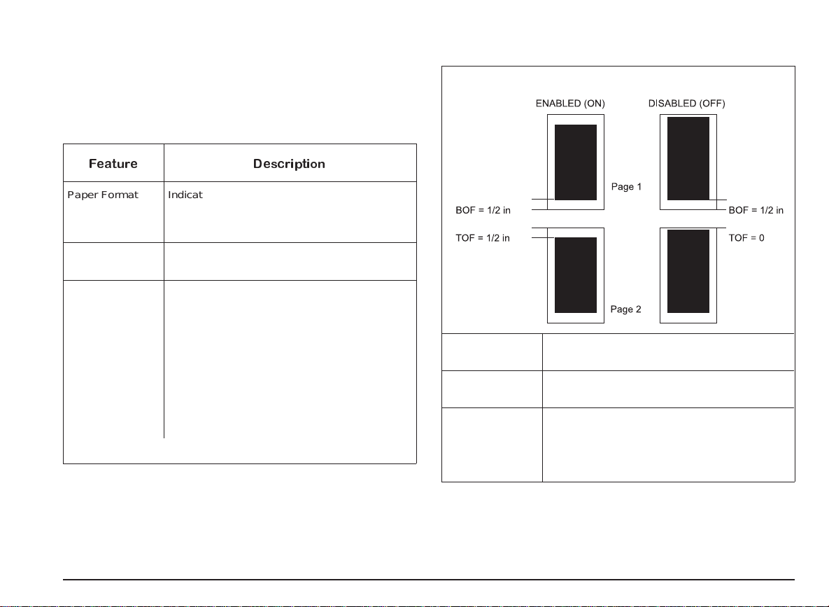
User-Definable Parameters
The following tables give a brief description of all the
features which can be selected using the printer set-up utility
Feature Description
Perforation skip mode (Skip TOF) (continued)
Paper Format Indicates the type and dimensions of the
Paper Device Means by which paper is fed to the printer:
Perforation skip
mode (Skip TOF)
document to be printed:
Letter; Legal; A4; vertical A5; COM10; DL; C5;
Executive; Free; C6; B6, note cards.
ASF, manual.
Affects only text, introducing a half inch
(12.7 mm) non-printable area at the top of
each page. In most cases, Perforation skip
mode ON will meet your requirements.
When Perforation skip mode is
overruns the lower limit of the text area will be
printed below the top margin of the next page.
When Perforation skip mode is
will be printed on the first physical print line of
the new page.
ON
, a line that
OFF
, the line
(continued)
Print Quality Type of printing quality:
Graphic
resolution
Line Terminator Normal: CR=CR; LF=LF; FF=FF
LQ (Letter Quality), Draft, etc.
Graphic printing resolution (dots per inch - dpi):
75 to 600.
AutoLF: CR=CR+LF; LF=LF; FF=FF
AutoCR: CR=CR; LF=LF+CR; FF=FF+CR
AutoCRLF: CR=CR+LF; LF=LF+CR;
FF=CR+FF
C-2 Programmable Printer Features
Page 83

Character Set Character Set: set of national or specialized
characters/ symbols to be used for printing:
CP 437 International
Roman 8
PC-8 Denmark/Norway
CP 850 (multilingual)
ECMA 94 Latin 1
ISO 4 United Kingdom
ISO 21 Germany
ISO 69 France
ISO 15 Italy
ISO 60 Norway 1
ISO 61 Norway 2
ISO 11 Sweden Names
ISO 10 Sweden
ISO 17 Spain
ISO 6 USASCII
ISO 2 IRV
ISO 16 Portugal
ISO 14 JIS ASCII
Legal
CP 860 Portugal
UNIX International
CP 863 French Canadian
PC Abicomp International
PC Abicomp Portugal
Type Style (Font) Shape, size, spacing, etc. of the character/
symbol set printed (all fonts are printed both in
portrait and landscape):
Courier Upright 10cpi 12pts
Courier Italic 10cpi 12pts
Courier Upright 16.67cpi 12pts
Letter Gothic Upright 10cpi 12pts
Letter Gothic Upright 12cpi 12pts
Letter Gothic Italic 12cpi 12pts
LetterGothic Upright 16.67cpi 9.5pts
BF Team Upright PS 14pts
BF Team Italic PS 14pts
BF Team Upright PS 12pts
BF Team Italic PS 12pts
BF Team Upright PS 10pts
BF Team Italic PS 10pts
BF Team Upright PS 8pts
BF Team Italic PS 8pts
Linea Upright PS 14pts
Linea Upright PS 12pts
Linea Italic PS 12pts
Linea Upright PS 10pts
Linea Italic PS 10pts
Linea Upright PS 8pts
Programmable Printer Features C-3
Page 84

Text Scale Mode Affects only text, reducing automatically the
current Line Feed setting to maintain a
half-inch (12.7 mm) non-printable area at the
foot of the page even for the maximum number
of print lines per page.
Possible ONLY with portrait orientation
selected and the Perforation Skip feature
DISABLED
.
Width Type Defines the dimensions of the
character/symbol printed, according to the
FONT selected (see parameter). Some fonts
are not affected:
normal; half width; half height; half width and
half height.
C-4 Programmable Printer Features
Page 85

Product Characteristics
Printing Technique
Non-impact, bubble ink jet, with water-resistant ink
Color and Monochrome Print Heads, either with
Replaceable Ink Cartridge or disposable
Throughput
Windows® environment
up to 6 pages per minute (ppm)
N.B.: this value may vary depending on the print mode (Draft/LQ), the
software application and/or the type of computer used.
Paper Handling
Automatic sheet feeder (ASF)
Manual (single documents)
ASF Capacity
Plain paper : up to 120 sheets (21 lbs paper)
Envelopes : up to 25 envelopes (21 lbs paper)
Note cards/thicker documents : up to 10 pieces (28 lbs
paper)
Special printing media : up to 40 sheets (24 lbs paper)
Paper Type
Plain office paper
Transparencies
High resolution glossy/coated papers
Envelopes
Note cards
T-Shirt Transfer
:
Paper Weight
Single sheets: 15 to 30 lbs
Envelopes: 19 to 25 lbs
Note cards/thicker documents: 25 to 35 lbs
Special printing media : 24 to 30 lbs
Paper Size
Single sheets: A4, A5, Letter, Legal, Executive
Envelopes: COM-10, DL, C5, C6, B6
Note cards: 4 x 6 in, 5 x 8 in, A6
Graphic Density
From 75 to 600 dpi
Resident Emulation
PCL III extended
Resident Fonts
-Courier:
orientation:Portrait and Landscape
pitch: 5, 8.33, 10, 16.67, 20, 33.34 cpi
size: 6, 12, 24 points
style: Upright (Italic 5, 10, 20 cpi)
- Letter Gothic:
orientation:Portrait and Landscape
pitch: 5, 6, 8.33, 10, 12, 16.67, 20, 24, 33.34 cpi
size: 4.75, 6, 9.5, 12 points
style: Upright (Italic 6, 12, 24 cpi; 6, 12, 24 points)
-BFTeam:
orientation:Portrait and Landscape
pitch: Proportional
size: 4, 5, 6, 7, 8, 10, 12, 14 points
style : Upright and Italic
Product Characteristics D-1
Page 86

- Linea:
orientation:Portrait and Landscape
pitch: Proportional
size: 4, 5, 6, 7, 8, 10, 12, 14 points
style: Upright (Italic 5, 6, 10, 12 points)
Character Sets
CP 437 International; Roman 8; PC 8 Denmark/ Norway; CP
850 Multilingual; ECMA-94 Latin 1; ISO 4 - United Kingdom;
ISO 21 - Germany; ISO 69 - France; ISO 15 - Italy; ISO 60 Norway 1; ISO 61 - Norway 2; ISO 11 - Sweden Names;
ISO 10 - Sweden; ISO 17 - Spain; ISO 6 - ASCII; ISO 2 IRV; ISO 16 - Portugal; ISO 14 - JIS ASCII; Legal; CP 860
Portugal; UNIX International; CP 863 French Canadian;
PC Abicomp International; PC Abicomp Portugal
Interface
Parallel Centronics (Bi-directional)
RAM
1 Mbyte
Product Certification
For USA and Canada
Safety regulations:
USA: UL 1950/478
Canada: CSA C22-2
Electromagnetic compatibility:
FCC part 15 Class B
Electrical Characteristics
Voltage
- 110 - 120 V, +/- 10%; 50 - 60 Hz
Power absorbed
- < 26W, in printing mode
-<2W,instandbymode
:
:
Operating Environment
Temperature: 60 - 95oF - 15 to 35oC
Relative Humidity: 20% - 80%, without condensation
Sound level
49 dB in LQ printing mode (continuous)
Physical Characteristics
Printer closed
Height 9.29 in (236 mm)
Width 18.11 in (460 mm)
Depth 18.30 in (465 mm)
Weight 9.9 lbs (4.5 kg)
D-2 Product Characteristics
Page 87

Getting Service and Support
Getting Help from N EC
Printer Technical Support is available Monday through
Friday, between the hours of 8:30AM and 8:00PM (Eastern
Standard Time) at 1-800-632-4650. Technical support for
this printer is provided free of charge during the one year
factory warranty.
Information regarding out-of-warranty repair is available by
calling the National Service Response Center at
1-800-632-4650.
You may also send electronic mail to support via the
following methods:
Internet address: tech-support@nectech.com
AOL keyword: NECTECH
Microsoft Network: NECTECH
You will always be required to provide information regarding
where and when the printer was purchased, regardless of
whether we have received your warranty card.
SuperScript 750C Printer Limited Warranty
The SuperScript 750C is warranted for one year from the
date of purchase under the NEC SuperScript Limited
Warranty. The warranty works as follows:
The Customer calls NEC Customer Service and Support
•
at 800-632-4650.
A recorded message will provide a list of various service
•
and support departments. Press the correct number for
Technical Support.
(Note: Many times a simple problem can be averted by
speaking with a technical support representative first).
If it is determined that the printer is defective, the support
representative w ill transfer you to another department to set
up the warranty exchange process.
SuperScript 750C Printer Limited Warranty
If you wish to receive a replacement printer by overnight
delivery, the service representative will obtain a major credit
card number from you, along with your shipping address.
An electronic credit check will be made in the amount of the
current price of the printer. If the defective printer is not
returned to NEC within 15 days, or you cannot prove that
your printer is still under warranty, your account will be
debited in this amount.
You must return the defective printer, properly packaged in
the original or replacement printer packaging, within fifteen
(15) days or your credit card account will be debited for the
current price of the the SuperScript 750C.
If you do not wish to provide a credit card number to NEC,
the service representative will provide you with an MRA
(Material Return Authorization) number for return of the
defective printer at your own expense. You must package
the printer in its original packaging, or equivalent, mark the
package with the MRA number, and return it to the address
provided. Upon receipt of the defective printer, NEC will
ship a replacement by overnight delivery.
Getting Service and Support E-1
Page 88

Warranty
NEC TECHNOLOGIES, INC. (here inafter NECTECH)
warrants this Product to be free of defects in material and
workmanship and agrees to repair or replace any part of the
enclosed unit w hich proves defective under these terms and
conditions.
Warranty Length
Labor is warranted for one (1) year from the date of the first
consumer purchase. Parts are warranted for one (1) year
from the date of the first consumer purchase.
Product modification, or failure to follow instructions
supplied with the Product.
(b) Alteration, repair or attempted repair by anyone not
authorized by NECTECH.
(c) Any shipment of the Product (claims must be presented
to the carrier).
(d) Removal or installation of the Product.
(e) Any other cause which does not relate to a Product
defect.
4. Cartons, carrying cases, batteries, external cabinets,
magnetic tapes, or any accessories used in connection
with the Product.
Warranty Coverage
This warranty may be enforced only by the first consumer
purchaser and it is not transferable.
Except as specified below, this warranty covers all defects
in material or workmanship in this Product. The following
are not covered by this warranty:
1. Any Product which is not distributed in the U.S.A. or
Canada by NECTECH or which is not purchased in the
U.S.A. or Canada by the first consumer purchaser.
2. Any Product on which the serial number has been
defaced, modified or removed.
3. Damage, deterioration or malfunction resulting from:
(a) Accident, misuse, abuse, neglect, fire, water, lightning or
other acts of nature, improper storage, unauthorized
5. This warranty covers only NECTECH-supplied
components. Service required as a result of third party
components is not covered under this warranty.
Warranty Support
NECTECH will pay labor and material expenses for covered
items, but we will not pay for the following:
1. Removal or installation charges.
2. Costs of initial technical adjustments (set-up), including
adjustment of user controls.
3. Payment of shipping and related charges incurred in
returning the Product for warranty repair.
E-2 Getting Service and Support
Page 89

Getting Warranty Service
You must return this Product directly to NECTECH factory
for warranty service. It shall be your obligation and expense
to ship the Product, freight prepaid, or to deliver it to a
NECTECH authorized service center or other facility
authorized by NECTECH to render the warranty services, in
either the original package or a similar package affording an
equal degree of protection.
NECTECH will send a replacement printer which will be, at
NECTECH’s option, new or like new, and will meet all of the
specification of the replaced printer. The replacement
printer will be shipped to you at NECTECH’s expense by
overnight delivery within the United States, upon receipt of
you defective printer, or upon receipt of a major credit card
number to guarantee receipt of the defective printer. The
warranty period on any replacement printer shall be either
(1) the remaining balance of the original one ( 1) year term,
or (2) ninety (90) days, whichever is longer. With the
exception of the duration, the terms and conditions of this
warranty shall apply to any replacement printer.
NECTECH may require that you provide the original bill of
sale or receipt as proof of purchase in order to obtain
warranty service. Please retain such proof of purchase with
your records.
Limitation of Damages and Implied
Warranties
NECTECH’S SOLE LIAB ILITY FOR ANY DEFECTIVE
PRODUCT IS LIMITED TO THE R EPAIR OR
REPLACEMENT OF THE PRODUCT AT OUR OPTION.
NECTECH SHALL NOT B E L IABL E FOR:
1. DAMAGE TO OTHER PROPERTY CAUSED BY ANY
DEFECTS IN THIS PRODUCT, DAMAGES BASED
UPON INCONVENIENCE, LOSS OF USE OF THE
PRODUCT, LOSS OF TIME OR DATA, COMMERCIAL
LOSS; OR
2. ANY OTHER DAMAGES, WHETHER INCIDENTAL,
CONSEQUENTIAL OR OTHERWISE.
THIS WARRANTY IS EXCLUSIVE AND IS IN LIEU OF ALL
OTHER WARRANTIES, EXPRESS OR IMPLIED,
INCLUDING BUT NOT LIMITED TO, THE IMPLIED
WARRANTIES OF MERCHANT ABILITY OR FITNESS FOR
A PARTICULAR PURPOSE. SOME STATES DO NOT
ALLOW THE EXCLUSION OF IMPLIED WARRANTIES OR
THE LIMITATION OR EXCLUSION OF LIABILITY FOR
INCIDENTAL OR CONSEQUENTIAL DAMAGES.
THEREFORE, THE ABOVE EXCLUSIONS OR
LIMITATIONS MAY NOT APPLY TO YOU.
This warranty gives you specific legal rights, and you may
also have other rights which vary from state to state.
For information, telephone 1-800-632-4650.
Note:
All Products returned to NECTECH for service MUST
have prior approval; this may be obtained by calling the
above number.
Getting Service and Support E-3
Page 90

This Product is warranted in accordance with the terms of
this limited warranty. Customers are cautioned that Product
performance is affected by system configuration, software,
the application, customer data, and operator control of the
system, among other factors. While NEC
TECHNOLOGIES, INC. Products are considered compatible
with many systems, the specific functional implementation
by customers of the Product may vary. Therefore, the
suitability of a Product for a specific purpose or application
must be determined by the customer and is not warranted
by NECTECH.
E-4 Getting Service and Support
Page 91

Glossary
Alignment
Control/adjustment of the horizontal and vertical printing
accuracy by means of a resident operator function.
ASCII-table
(American Standard Code of Information Interchange);
standardized code and character assignment table from 0 to
127 decimal.
ASF
(Automatic Sheet Feeder); paper insertion device
incorporated in the upper rear part of the printer.
BIM
(Bit Image Mode); graphic printing mode, in which a byte is
not interpreted as character. Its bits cause the individual
nozzles of the print head to print or not.
bit
Smallest information item; a signal set to 0 or 1. Eight bits
make one byte ( character).
BOF
(Bottom Of Form); the area at the foot of each form, in
which printing will not be possible (it will be skipped
automatically).
buffer
Built-in memory in the printer, in which data will be stored
until it is printed.
byte
Standard unit for character/symbol representation. A byte
consists of 8 bits.
character generator
Resident printer program, which converts a character code
(byte) into a pixel matrix for printing.
character set
Assignment table between a code and a specific printable
character (usually in connection with national languages).
cpi
Characters per inch; indicates the number of characters
which can be printed in one inch.
dB (decibel)
Unit of measurement for sound.
default
Standard initial setting of a feature or a parameter. Can
usually be modified.
dithering
Printing method by which color dots are combined on a
document to achieve a range of colors.
dot size
Size of the smallest element used to create the character
image (default value: 1/72 in).
dpi
Dots per inch; indicates the number of dots which can be
printed in one inch.
Glossary F-1
Page 92

driver
Software program which controls output to the printer and
does necessary code conversions between application
program and printer.
grayscale
Printing method by which dots from a color file are
combined on a document which is printed in monochrome
(black) and shades of gray.
economy print mode
Low dot resolution print mode. Allows ink saving.
elementary spacing
Smallest possible horizontal or vertical movement of the
print head.
emulation
Set of commands that can be interpreted by the printer
and/or driver.
ESCAPE character
Special character with the decimal value 27 (ESC), which
tells the printer that the following character(s) form a control
sequence.
ESCAPE sequence
Set of characters, s tarting with the ESC character, which
controls an action of the printer as defined by its emulation.
factory setting s
Printer settings defined by the manufacturer; also known as
default settings (see item).
firmware
Built-in control intelligence of the printer which cannot be
changed by the user.
font
Set of characters available in a certain typeface and size
(see also items “cpi” and “dot size”).
halftoning
Printing method by which shades of gray or of color are
produced by the variable concentration of dots. When
printing in color, the proximity of different colored ink dots
creates the impression of new colors.
handshaking
Signal exchange between the printer and the controlling
system, which regulates the loading of data to the printer’s
buffer and avoids overflow of this buffer.
hex-dump
Printing mode in which the transmitted characters (and also
control codes) are printed as two digit hexadecimal codes.
Used for debugging.
initialization
Process at printer switch-on in which the printer executes
an automatic self-diagnosis of its hardware and loads the
settings as defined in programming (set up). Reset by
command also causes (re-)initialization of the printer (but
without hardware check).
interface
Physical (with cable) and logical (synchronization and
interpretation of signals) connection of the printer with a
host system/computer.
ISO table
(International Standardization Organization); a convention
which assigns to certain ASCII codes (see item) a
one-per-nation set of special European characters.
F-2 Glossary
Page 93

landscape
Page orientation in which the characters are printed along
the long side of the paper.
pitch
The character spacing measured in characters per inch (cpi
- see item).
LOCAL condition
Another word for the printer Off-Line state (see item).
nozzles
Microscopic holes on the print head through which ink is
expelled to form the character/symbol to be printed.
off-line
Printer operating condition in which data and commands via
interface are accepted until the input buffer is full, but are
not executed. It permits the execution of operations
commanded via the operator panel.
on-line
Operating condition in which the printer is completely
controlled by its host.
parallel interface
Means of connecting the printer to a computer with a
defined standard plug and pin assignment . Data is
transmitted by 8 “parallel” lines, i.e. one complete byte at a
time.
parameter
A command or feature, the value of which may be varied
(see setting).
PCL commands
(Printer Command Language); resident emulation.
A proprietary name of Hewlett-Packard.
portrait
Page orientation in which the characters are printed across
the short side of the paper.
print buffer
An intermediate buffer in which data coming from the line
buffer is stored, until the transmission of a code which
commands printing.
print quality
LQ (Letter Quality); printing with a high character definition
which approaches solid character profiles.
Draft; printing with reduced character definition, to give a
higher print speed.
printer monitor
On-screen user interface, containing information on the
current print job and printer care operations that can be run
by the user.
RAM
(Random Access Memory); a memory area which may be
written to repeatedly, e.g. the print buffer (volatile, i.e. loses
contents when overwritten or at printer switch-off).
release X.X
Indicates the version/updating level of the firmware.
reset
Commands the printer to clear the buffer and all temporary
settings, returning to an initial switch-on state.
Glossary F-3
Page 94

resolution
Print density defined as the number of dots printed per inch.
user settings
Parameter values defined by the user.
ROM
(Read Only Memory); a non-volatile memory area that can
be read (used) but not modified and contains the built-in
character generator, command code emulation, etc.
scaleable font
A file containing the basic elements of a set of characters
the size of which can be enlarged and/or reduced (within the
specifications indicated) by the user.
setting
The value of a parameter, command or feature.
SET-UP
An operating procedure in which it is possible to define the
printer parameter settings and memorize them.
standby
Printer status in which the printer is powered but dormant.
Occurs after a certain period o f inactivity.
throughput
The optimum average output (in pages per minute) of the
printer.
TOF
(Top Of Form); the space on top of a form in which printing
is not possible. Will be skipped automatically on the
execution of an FF.
word length
(7 or 8 bits); refers to the format in which a byte of data is
transmitted to and interpreted by the printer.
TrueType font
Another name for bit-map fonts.
F-4 Glossary
Page 95

INDEX
Color printing
command codes, A-10
Connecting the printer, 1
to a computer, 2
to the electrical power supply, 2
A
Aligning the print heads, 10, 11, 21
ASF
capacity, 23, 24, C-1
document support, 3
use of intermediate right margin, 24
ASF capacity
envelopes, 23, 24
note cards, 23
plain paper, 23, 24
special printing media, 23, 24
thicker documents, 23, 24
C
Carton contents, 1
Character sets, C-2
available through SETUP utility, B-3
command codes, A-1, A-2
default setting, B-1
Check print accuracy
SEE Aligning the print heads
Cleaning the print heads, 22
key combination, 40, 14, 22
Color print head
ink cartridge replacement, 20
insertion, 4, 5
nozzles test, 38
removal, 19
D
Defaultsettings, B-1
how to restore, 31
Demo page
how to obtain, 10, 12
key combination, 14
Document supports
for ASF, 1
for manual feeder, 1
how to insert, 3
output tray extension, 1
DOS environment, 30, 31
Drivers
diskettes, 5
how to change parameters, 28, 29
how to save parameters, 29
installation, 8
on-line help, 28, 29
user interface, 28, 29
E
Electrical characteristics, C-2
Electrical data plate, 2
Emulation resident, C-1
End of ink condition, 18, 20
light indicator status, 16
Index G-1
Page 96

Envelopes
accepted weight, 23
ASF capacity, 23, 24, C-1
dimensions, 24
formats, C-1
insertion, 24, 25
print area, 26
types, 24, 26
weight, 23, C-1
F
Factory settings, B-1
Failure
light indicator status, 17
Fonts, C-1
available through SETUP utility, B-3
command codes, A-1, A-2
default setting, B-1
PCL III + emulation, C-1, C-2
resident, C-1, C-2
G
Graphic printing
command codes, A-7, A-8
H
Help
drivers, 28, 29
problems and solutions, 34, 35, 36, 37, 38, 39, 40, 41
Hex dump, 40
key combination, 14
I
Identifying the printer parts, 1
Ink cartridge, 18, 20
how to replace, 20
Ink counter reset, 19, 20
indicator light status, 16
key combination, 15
Ink jet print heads, 1, 18, 19, 20, 21, 22
alignment, 10, 11, 21
cleaning, 22
color print head insertion, 4, 5
counter reset, 19, 20
electrical contacts, 4
how to clean, 11
how to insert, 4, 5
how to remove, 18, 19
how to replace,18, 19
how to replace the ink cartridge, 20
ink counter reset, 15
instructions on templates, 17
monochrome print head insertion, 4
Photo Cartridge, 18, 19
printing nozzles, 4
rest position, 19, 20
Inserting the document supports, 3
Inserting the print heads, 4
Installing printer software, 5
driver installation procedure, 6, 8
preparation, 5, 6
Interface
connecting a parallel cable, 2
parallel, C-2
parallel port setting, 8, 35
G-2 Index
Page 97

K
N
Key combinations
access to special functions, 14
cleaning print heads, 14
demo page, 14
hex dump, 14
print test (complete), 14
print test (first page only), 14
reset ink counter, 15
Keys, 13, 14, 15
basic functions, 13
special functions, 14, 15
L
Light indicators (LEDs), 16, 17
end of ink condition, 16
failure condition, 17
paper jam condition, 17
paper out condition, 16
standby condition, 16
Loading envelopes, 24
Loading paper, 4
M
Manual document support
insertion, 3
use of intermediate right margin, 3, 25
Monochrome print head
ink cartridge replacement, 20
insertion, 4
nozzles test, 38
removal, 19
Narrow documents
insertion, 24, 25
measurements, 24, 25, 27
use of intermediate right margin, 24, 25
Note c ards
ASF capacity, 23, C-1
formats, C-1
types, 24
weight, 23, C-1
Nozzles
how to clean, 40, 22
test, 38
O
Operating environment, 33, C-2
Operator panel, 12, 13, 14, 15, 16, 17
keys, 13, 14, 15
light indicators (LEDs), 16, 17
Options, 43
Others (command codes)
command codes, A-9
Output tray extension
how to insert, 3
how to position,3
P
Page format
available through SETUP utility, B-2
command codes, A-5
default value, B-1
Index G-3
Page 98

Paper, 23, 24, 25, 26, 27, C-1
accepted weight of plain paper, 23
characteristics, C-1
dimensions, 24, 25
formats, C-1
formats accepted, 24, 25
inserting the document supports, 3
loading, 4, 24
recommended weight of plain paper, 23
solutions to problems with, 35, 36
types, 23, C-1
weight, 23, C-1
weight of thicker documents, 23
Paper jams
causes, 36
howtoavoid,4,35
how to clear, 36
in the ASF, 36
in the printer, 36
light indicator status, 36, 17
Paper out
light indicator status, 36, 16
print head carriage position, 34, 36, 16, 17
template, 17
PCL III + emulation
fonts, C-1, C-2
Perforation skip
default setting, B-1
parameter description, B-2
Photo cartridge, 18, 21
insertion, 21
Photo kit, 29, 30
driver installation, 29, 30
Physical characteristics, C-2
Plain paper
ASF capacity, 23, 24, C-1
Preparation for use
connecting to a PC/host system, 2
connecting to the electrical power supply, 1
inserting the document supports, 3
inserting the print heads, 4, 5
loading a printer driver, 5
Print area on document, 25, 26, 27
envelopes, 26
note cards, 27
single sheets, 26
Print attributes
command codes, A-3, A-4
Print definition
graphics, C-1
Print head care, 21, 22
cleaning the print heads (Clean), 22
Print position
command codes, A-6, A-7
Printspeed,C-1
Print test, 38
color nozzles test, 38
contents, 38
how to interrupt, 38
how to obtain, 38, 12
how to resume, 38
key combination (first page only), 14
key combination (full print-out), 14
monochrome nozzles test, 38
nozzle test, 38
troubleshooting, 38
Printer care
aligning the print heads (Align), 10, 40, 11, 21
checking print accuracy, 10, 11
cleaning the print head (Clean), 11
cleaning the print heads (Clean), 40, 22
environment, 33
printing the demo page (Demo), 10, 34, 12
running the print test (Print test), 38
G-4 Index
Page 99

running the print test (Test), 12
transportation, 33
Printer characteristics, C-1, C-2
Printer monitor, 11
contents, 5
how to activate, 9
how to use, 9, 10, 11, 12
print job status, 11
printer care functions, 38, 40, 11, 22
Printer set-up utility, 30, 31
access to, 31
exit from, 31
how to restore default settings, 31
how to select parameters, 31
Printer states, 12
Printing
demo page, 10, 12
print test, 38, 12
troubleshooting, 39, 40, 41
Problems and solutions, 34, 35, 36, 37, 38, 39, 40, 41
Product certification, C-2
Programmable printer features, B-1, B-2, B-3, B-4
factory settings, B-1
user-definable parameters, B-2, B-3, B-4
Q
Quality
envelopes, 23
paper, 23
printing, command codes, A-4
printing, poor, 40
printing, setup parameters, B-2
Quickstart,1,2,3,4,5,6,7,8,9,10
R
Re-activate end of ink signal
SEE Ink counter reset
Replaceable ink cartridge, 20
Resolution
graphics, C-1
S
SETUP utility
user-definable parameters, B-2, B-3, B-4
Single sheets
dimensions, 24
types, 24
Software
printer SET-UP utility, 30, 31
Special functions
key combination, 14
light indicator status, 14
with printer closed, 14, 15
with printer open, 14
Special printing media
ASF capacity, 23, 24, C-1
types, 23
weight, 23, C-1
Speed,C-1
Standby, 2, 12
light indicator status, 16
Supplies, 43
Index G-5
Page 100

T
U
Templates, 17
ink jet print heads, 17
paper out, 17
Text scale mode
default setting, B-1
parameter description, B-4
Thicker documents
ASF capacity, 23, 24, C-1
weight, 23, C-1
Throughput, C-1
Troubleshooting
demo page, 34
faint characters, 37
host, 35
installation, 34
missing dots, 38
no printing, 34, 37, 38, 39
paper, 35, 36
parallel port setting, 8, 35
powering the printer, 34
print heads, 37, 38, 40
print quality (character alignment), 40
print quality (leggibility), 40
print test, 34
printing, 37, 39, 40, 41
strange characters, 40
Windows® environment, 41
Unpacking, 1
Use of intermediate right margin
on ASF, 24
on manual feed channel, 25
User interface, 11
operator panel, 11, 12, 13, 14, 15, 16, 17
printer monitor, 11
templates, 11, 17
W
Weight
envelopes, C-1
note cards, C-1
paper, C-1
printer, C-2
special printing media, C-1
thicker documents, C-1
Windows® environment, 28, 29
access to driver parameters, 28
G-6 Index
 Loading...