


SERVICE MANUAL
C 541 COMPACT DISC PLAYER
NAD
C 541
COMPACT
DISC PLAYER
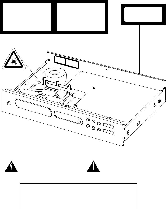
SAFETY INFORMATION
CAUTION
CAUTION - INVISIBLE LASER RADIATION WHEN OPEN AND INTERLOCKS DEFEATED. AVOID EXPOSURE TO BEAM.
ADVARSEL - USYNLIG LASERSTRÅLING NÅR DEKSEL ÅPNES OG SIKKERHEDSLÅS BR YTES. UNNGÅ EKSPONERING FOR STRÅLEN.
ADVARSEL- USYNLIG LASERSTRÅLING VED ÅBNING, NÅR SIKKERHEDSAFBRYDERE ER UDE AF FUNKTION. UNDGÅ UDSÆTTELSE FOR STRÅLING.
VARING - OSYNLING LASERSTRÅLNING NÄR DENNA DEL ÄR ÖPPNAD OCH SPÄRRAR ÄR URKOPPLADE. STRÅLEN ÄR F ARLIG.
VARO! - AVATTAESSAJASUOJALUKITUS OHITETTAESSAOLET ALTTIINANÄKTMÄTÖNTÄ LASERSÄTEIL YLLE. ÄLÄ KAISO SÄTEESEEN.
VORSICT!- UNSICHTBARE LASERSTRAHLUNG TRITTAUS, WENN DECKEL GEÖFFNET UND WENN SICHERHEITSVERRIEGELUNG ÜBERBRÜCKT IST. NICHT DEM STRAHLAUSSETZEN.
|
CATUION |
|
|
|
|
|
|
|
ADVARSELHGKJDHSGKJHGSJK |
VARING |
|
|
ADVARSELKBVNCLKNBCVLKNLKNVLKNCVNCLVK |
|
|
|
HGKJDHSGKJHGS |
KLHKFG;LKNG;LKJGF;LKJGF;LKJFL;SJK |
|
|
HFKLJHJLDKLJLKDJLKFHJHSGMMKJHGSJK |
||
|
HGKLFH;L;HJMNMD |
VARO! |
HGKJDHSGKJHGKLGDJH |
|
|
KBVNCLKNBCVLKNLKNVLKNCVNCLVKVORSICT!HGKJDHSGKJHJBJKBKJBJKGS |
|
|
|
JHFKLJHJLDKLJLKDJLKFHJHSGKJHGSJK |
|
|
|
|
HGKLFH;L;HHBHHJD |
|
|
|
|
CLASS 1
LASER PRODUCT
The lightning flash with arrowhead, within an equilateral tri- |
The exclamation point within an equilateral triangle is intend- |
angle is intended to alert the user of the presence of |
ed to alert the user of the presence of important operating |
uninsulated "dangerous voltage" within the product’s |
and maintenance (servicing) instructions in the literature |
enclosure; that may be of sufficient magnitude to consti- |
accompanying the appliance. |
tute a risk of electric shock to persons. |
|
|
|
THIS DEVICE COMPLIES WITH PART 15 OF THE FCC RULES.
OPERATION IS SUBJECT TO THE FOLLOWING TWO CONDITIONS:-
(1)THIS DEVICE MAY NOT CAUSE HARMFUL INTERFERENCE, AND
(2)THIS DEVICE MUST ACCEPT ANY INTERFERENCE RECEIVED, INCLUDING INTERFERENCE THAT MAY CAUSE UNDESIRED OPERATION.
2

SERVICE SAFETY PRECAUTIONS
1.Replacing the fuses
CAUTION: FOR CONTINUED PROTECTION AGAINST THE RISK OF FIRE REPLACE ONLY WITH SAME TYPE OF FUSE.
Reference No |
Part Number |
Description |
|
M507 |
*AH |
5120-0052-0 |
FUSE T1.6A 250V 5X20MM |
M512, M513 *AH |
5120-0020-0 |
FU T1A 250V UL/CSA 5X20 |
|
M514 |
*AH |
5120-0026-0 |
FU T315MA L 250V UL/CSA |
M507 |
*C |
5120-0050-0 |
FUSE T1.6A 250V 5X20MM |
M512, M513 *C |
5120-0018-0 |
FU T1A 250V SEMKO/VDE |
|
M514 |
*C |
5120-0027-0 |
FU T315MAL 250V |
NOTE:
<*AH > : USA, CANADIAN MODEL ONLY.
<*C > : EUROPEAN MODEL ONLY.
2. Safety check out
(Only U.S.A. model)
Before returning the product to the customer, make leakage current or resistance measurements to determine that exposed parts are acceptably insulated from the supply circuit.
Parts marked with the symbol  are critical with regard to the risk of fire and electric shock.
Replace only with parts recommended by the manufacturer.
CONTENTS
DESCRIPTION PAGE
SPECIFICATIONS . . . . . . . . . . . . . . . . . . . . . . . . . . . . . . . . . . . . . . . . . . . . . . . . . . . . . . . . . . .4 REAR PANEL / FRONT PANEL . . . . . . . . . . . . . . . . . . . . . . . . . . . . . . . . . . . . . . . . . . . . . . . . .5 DISASSEMBLY INSTRUCTIONS . . . . . . . . . . . . . . . . . . . . . . . . . . . . . . . . . . . . . . . . . . . . . . . .6 BLOCK DIAGRAM . . . . . . . . . . . . . . . . . . . . . . . . . . . . . . . . . . . . . . . . . . . . . . . . . . . . . . . . . . .7 WIRING DIAGRAM . . . . . . . . . . . . . . . . . . . . . . . . . . . . . . . . . . . . . . . . . . . . . . . . . . . . . . . . . .8 RF PATTERN TESTING . . . . . . . . . . . . . . . . . . . . . . . . . . . . . . . . . . . . . . . . . . . . . . . . . . . . . . .9
IMPORTANT NOTES . . . . . . . . . . . . . . . . . . . . . . . . . . . . . . . . . . . . . . . . . . . . . . . . . . . . .10-11 PCB LAYOUT . . . . . . . . . . . . . . . . . . . . . . . . . . . . . . . . . . . . . . . . . . . . . . . . . . . . . . . . . . .12-14 SCHEMATIC DIAGRAM . . . . . . . . . . . . . . . . . . . . . . . . . . . . . . . . . . . . . . . . . . . . . . . . . . .15-16 IC BLOCK DIAGRAM . . . . . . . . . . . . . . . . . . . . . . . . . . . . . . . . . . . . . . . . . . . . . . . . . . . . .17-19
TROUBLESHOOTING GUIDE . . . . . . . . . . . . . . . . . . . . . . . . . . . . . . . . . . . . . . . . . . . . . . . . .20
ELECTRICAL PARTS LIST . . . . . . . . . . . . . . . . . . . . . . . . . . . . . . . . . . . . . . . . . . . . . . . . .21-26 MECHANISM EXPLODED VIEW . . . . . . . . . . . . . . . . . . . . . . . . . . . . . . . . . . . . . . . . . . . . . . .27 MECHANISM EXPLODED VIEW PARTS LIST . . . . . . . . . . . . . . . . . . . . . . . . . . . . . . . . . . . . .28 EXPLODED VIEW OF LASER CD11CA-G . . . . . . . . . . . . . . . . . . . . . . . . . . . . . . . . . . . . . . . .29
EXPLODED VIEW PARTS LIST OF LASER CD11CA-G . . . . . . . . . . . . . . . . . . . . . . . . . . . . . .30
EXPLODED VIEW . . . . . . . . . . . . . . . . . . . . . . . . . . . . . . . . . . . . . . . . . . . . . . . . . . . . . . . . . .31 EXPLODED VIEW PARTS LIST . . . . . . . . . . . . . . . . . . . . . . . . . . . . . . . . . . . . . . . . . . . . . . . .32
PACKING DIAGRAM . . . . . . . . . . . . . . . . . . . . . . . . . . . . . . . . . . . . . . . . . . . . . . . . . . . . . . . .33
3
SPECIFICATIONS
Disc Capacity . . . . . . . . . . . . . . . . . . . . . . . . . . . . |
One Disc, 120 or 80 mm |
Decoding . . . . . . . . . . . . . . . . . . . . . . . . . . . . . . . |
BURR-BROWN Delta Sigma 24bit |
Digital Filter . . . . . . . . . . . . . . . . . . . . . . . . . . . . . |
8 Times oversample |
Analog Filter . . . . . . . . . . . . . . . . . . . . . . . . . . . . . |
4 pole active |
Frequency Response . . . . . . . . . . . . . . . . . . . . . . |
+/- 0.5 dB, 5Hz - 20kHz |
De-Emphasis Error . . . . . . . . . . . . . . . . . . . . . . . . |
+/- 0.3 dB |
THD (at 0 dB, 1kHz) . . . . . . . . . . . . . . . . . . . . . . . |
0.007% |
Intermodulation Distortion . . . . . . . . . . . . . . . . . . . |
< - 100 dB |
(19 + 20 kHz) |
|
Dynamic Range . . . . . . . . . . . . . . . . . . . . . . . . . . |
96 dB |
Linearity . . . . . . . . . . . . . . . . . . . . . . . . . . . . . . . . |
+/- 0.5 dB, 0 dB to -80 dB |
Signal / Noise Ratio (A-Weight) . . . . . . . . . . . . . . |
³102 dB, De-Emphasis on |
|
³102 dB, De-Emphasis off |
Channel Separation 1kHz . . . . . . . . . . . . . . . . . . |
>90 dB |
10 kHz . . . . . . . . . . . . . . . . |
>80 dB |
Wow and Flutter . . . . . . . . . . . . . . . . . . . . . . . . . . |
Unmeasurable (Quartz Crystal Accuracy) |
Output Impedance . . . . . . . . . . . . . . . . . . . . . . . . |
200 ½ |
Output Level at 0 dB . . . . . . . . . . . . . . . . . . . . . . . |
2.2 V rms |
Digital Error Correction . . . . . . . . . . . . . . . . . . . . . |
CIRC with double error correction |
|
in C1 and C2 |
Digital Code Output . . . . . . . . . . . . . . . . . . . . . . . |
Sony / Philips Serial data format |
CONTROLS
Play / Pause, Stop, Random, Skip (< >), Scan (< >), Open, Time, Repeat.
PHYSICAL SPECIFICATIONS |
|
Dimensions |
435 x 80 x 285 mm |
(Width x Height x Depth) |
|
Net weight |
4 kg (8.8 lbs) |
Shipping weight |
5.1 kg (11.22 lbs) |
4
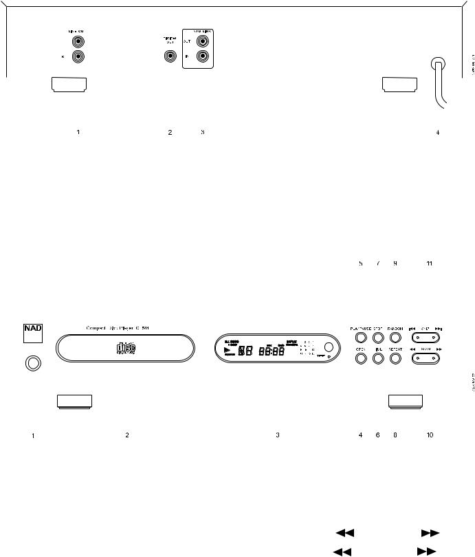
REAR PANEL / FRONT PANEL
REAR PANEL
|
|
|
|
|
|
|
|
|
|
|
|
|
|
|
|
|
|
|
|
|
|
|
|
|
|
|
|
|
|
|
|
|
|
|
|
|
|
|
|
|
|
|
|
|
|
|
|
|
|
|
|
|
|
|
|
|
|
|
|
|
|
|
|
|
|
|
|
|
|
|
|
|
|
|
|
|
|
|
|
|
|
|
|
|
|
|
|
|
|
|
|
|
|
|
|
|
|
|
|
|
|
|
|
|
|
|
|
|
|
|
|
|
|
|
|
|
|
|
|
|
|
|
|
|
|
|
|
|
|
|
|
|
|
|
|
|
|
|
|
|
|
|
|
|
|
|
|
|
|
|
|
|
|
|
|
|
|
|
|
|
|
|
|
|
|
|
|
|
|
|
|
|
|
|
|
|
|
|
|
|
|
|
|
1. |
LINE OUT |
|
|
|
|
|
|
|
|
3. NAD LINK |
|
|
|
|||||||||
2. |
DIGITAL OUT |
|
|
|
|
|
|
|
|
4. AC LINE CORD |
|
|
|
|||||||||
FRONT PANEL
|
|
|
|
|
|
|
|
|
|
|
|
|
|
|
|
|
|
|
|
|
|
|
|
|
|
|
|
|
|
|
|
|
|
|
|
|
|
|
|
|
|
|
|
|
|
|
|
|
|
|
|
|
|
|
|
|
|
|
|
|
|
|
|
|
|
|
|
|
|
|
|
|
|
|
|
|
|
|
|
|
|
|
|
|
|
|
|
|
|
|
|
|
|
|
|
|
|
|
|
|
|
|
|
|
|
|
|
|
|
|
|
|
|
|
|
|
|
|
|
|
|
|
|
|
|
|
|
|
|
|
|
|
|
|
|
|
|
|
|
|
|
|
|
|
|
|
|
|
|
|
|
|
|
|
|
|
|
|
|
|
|
|
|
|
|
|
|
|
|
|
|
|
|
|
|
|
|
|
|
|
|
|
|
|
|
|
|
|
|
|
|
|
|
|
|
|
|
|
|
|
|
|
|
|
|
|
|
|
|
|
|
|
|
|
|
|
|
|
|
|
|
|
|
|
|
|
|
1. |
POWER ON / OFF |
7. |
STOP |
|
|
|
|
|
|
|
|
|
||||||
2. |
DISC DRAWER |
8. |
REPEAT |
|
|
|
|
|
|
|
|
|
||||||
3. |
DISPLAY |
9. |
RANDOM |
|
|
|
|
|
|
|
|
|
||||||
4. |
OPEN |
10. |
SCAN Back ( |
) / Forward ( |
) |
|
||||||||||||
5. |
PLAY / PAUSE |
11. |
SKIP Back ( |
|
|
) / Forward ( |
|
) |
|
|||||||||
|
|
|||||||||||||||||
6. |
TIME |
|
|
|
|
|
|
|
|
|
|
|
|
|
|
|||
5
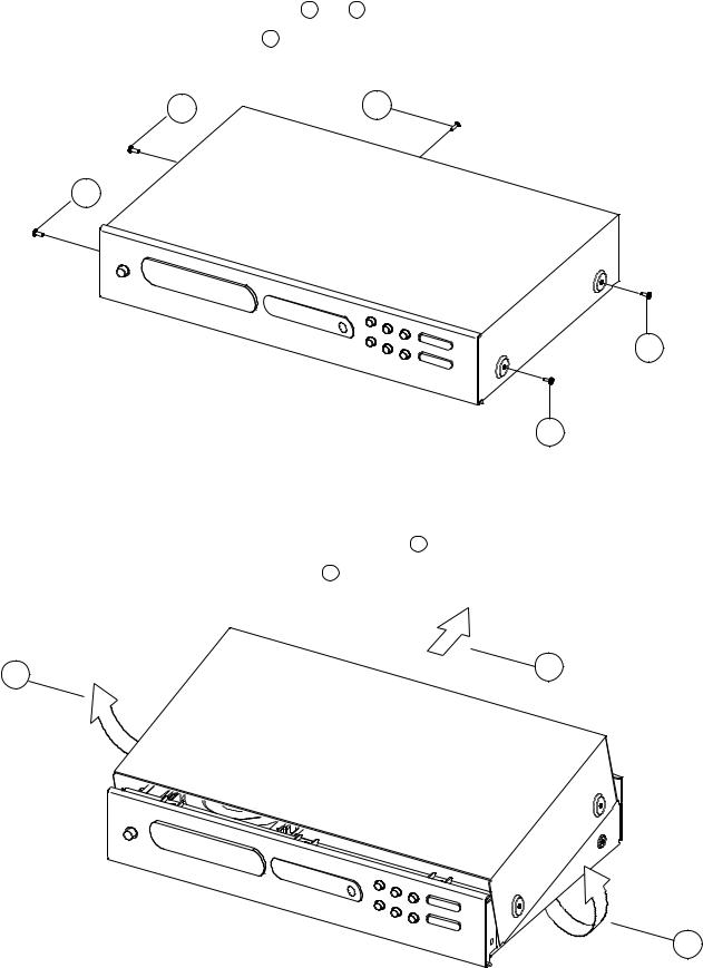
DISASSEMBLY INSTRUCTIONS
1.Remove machine screws M 4.0 x 6.0 ( 1 to 4 ) from the side panels.
Remove tapping screw 3.0 x 8.5 5 from the back panel.
Refer to Figure No.1.
4 |
5 |
3
2
Figure No.1 |
1 |
|
2. Pull both sides of the TOP COVER slightly outwards 6 and tilt approx. 35˚ and then remove in the direction as indicated by the arrow 7 . Refer to Figure No.2.
6 |
7 |
|
6
Figure No.2.
6
|
|
|
|
|
|
|
|
|
|
|
KEYBOARD |
|
|
|
|
|
|
|
|
|
|
||||
|
|
|
|
|
|
|
|
|
|
|
|
|
|
|
|
|
|
|
|
M501 |
|
|
M319 |
|
|
|
|
|
|
|
|
|
|
|
|
|
|
|
|
|
|
|
|
|
|
|
RCA JACK |
||||
|
|
|
|
|
|
|
|
|
|
|
|
REPEAT |
|
|
|
|
VFL DISPLAY |
|
|||||||
|
|
|
|
|
|
|
|
|
|
|
|
|
|
|
|
NAD LINK |
NAD LINK |
||||||||
|
|
|
|
|
|
|
|
|
|
|
|
|
|
|
|
|
|
||||||||
|
|
|
|
|
|
|
|
|
|
M110 |
M109 |
M104 |
|
M112 |
M111 |
|
|
||||||||
|
|
|
|
|
|
|
|
|
|
|
|
|
|
IN |
|
|
OUT |
||||||||
|
|
|
|
|
-22V |
|
|
|
|
|
|
|
|
|
|
|
|
|
|
|
|
|
|
||
|
|
|
|
|
|
|
|
|
|
|
|
|
|
|
|
|
|
|
|
|
|
|
|
|
|
|
|
-12V |
|
D510-D511 |
|
|
|
|
|
|
|
|
|
TIME |
RANDOM |
|
|
9 |
10 |
|
11 |
||||
+8V |
+5V |
+12V |
5V |
|
|
|
|
M101 |
M103 |
M102 |
|
M108 |
M106 |
|
|
|
|||||||||
|
ZENER DIODES |
|
|
|
|
|
|
|
|
U403 |
|
||||||||||||||
|
|
|
|
|
|
|
|
|
|
|
|
|
|
|
|
|
|
|
|
|
|
||||
U501,U507 |
U502-3,U506 |
|
|
|
|
|
|
|
|
|
|
|
|
|
|
|
|
|
74HC00 NAND GATE |
||||||
|
|
|
|
|
|
|
|
|
|
|
|
|
|
|
|
|
|
|
|
|
|
||||
|
DIGITAL |
ANALOGUE |
|
|
|
|
|
|
|
|
|
|
|
|
|
|
|
|
|
|
8 |
|
|
12 13 |
|
|
POWER |
POWER |
|
D506-D508 |
|
|
|
|
|
|
|
|
|
|
|
|
|
|
|
|
|
|
|
||
|
|
|
|
|
|
|
|
|
|
|
|
|
|
|
|
|
|
|
|
|
|
|
|
||
|
|
|
|
|
RECTIFIER |
|
POWER |
|
|
|
|
|
|
|
|
|
|
|
|
|
|
|
|
||
|
|
|
|
|
DIODES |
|
|
|
|
|
|
|
|
|
|
|
|
|
|
|
|
|
|
||
|
|
|
|
|
|
TRANSFORMER |
|
57 |
|
58 |
|
|
|
|
1 |
16 |
|
|
|
|
|
||||
|
D514-D517 |
D501-D504 |
|
|
|
|
|
|
|
|
|
|
|
|
|
|
|||||||||
|
|
|
|
|
|
|
|
|
|
|
|
|
|
|
|
19 |
24 |
|
9 |
U402 |
15 |
||||
|
RECTIFIER |
RECTIFIER |
|
|
|
|
|
|
|
|
|
|
|
|
U401 LC866008 |
|
|||||||||
|
|
|
|
|
|
|
|
|
|
|
|
|
|
|
|
|
|
||||||||
|
DIODES |
DIODES |
|
|
|
|
|
|
|
|
|
|
|
|
|
|
|
|
NAD LINK |
||||||
|
|
|
|
|
|
M500 |
|
|
|
|
|
|
SYSTEM CONTROL CPU |
64 |
11 |
|
|||||||||
|
|
|
|
|
|
|
|
|
|
|
|
|
|
|
|
MICRO- |
|
||||||||
|
|
|
|
|
|
|
|
|
|
|
|
|
|
|
|
& VFL DISPLAY DRIVER |
|
|
|
|
|||||
|
|
|
|
|
|
|
|
|
|
|
|
|
|
|
|
|
|
CONTROLLER |
|||||||
|
|
|
|
|
|
|
|
|
|
|
|
|
41 |
|
35 |
33 |
39 |
|
|
|
8 |
||||
|
|
|
|
|
|
|
|
|
|
AC POWER I / P |
|
|
|
|
|
|
|
|
|
||||||
|
|
|
|
|
|
|
|
|
|
|
|
|
|
|
|
|
|
|
|
|
|
|
|
||
|
|
|
|
|
|
|
|
|
|
|
|
44 |
43 |
47 |
36 |
34 |
40 |
48 |
|
|
|
|
|
|
|
|
|
|
|
|
|
|
|
|
|
|
|
|
|
|
|
|
|
|
|
|
1 |
|
|
|
|
|
|
|
|
|
|
|
|
|
|
|
|
|
|
|
|
|
|
|
|
|
M113 |
|
|
|
|
|
|
|
|
|
|
|
|
|
|
|
|
|
|
|
|
|
|
|
|
|
REMOTE |
|
|
|
|
|
|
|
|
|
|
|
|
|
|
|
|
|
|
|
|
|
|
|
|
|
SENSOR |
|
|
|
|
7 |
|
|
|
|
|
|
|
|
|
|
|
|
|
|
|
|
|
|
|
|
|
|
|
CD AUDIO |
|
|
|
|
|
|
|
|
|
|
|
|
|
|
|
|
|
|
|
|
|
|
|
|
|
O/P |
|
|
|
|
|
|
|
|
|
|
|
|
|
|
|
|
|
|
|
|
|
|
|
|
|
|
|
CD MECHANISM UNIT |
|
|
|
|
|
|
|
|
|
|
|
|
|
|
Q401Q403 |
|
|
|
L |
|
|
J317 |
|||
|
|
|
|
|
|
|
|
|
|
|
|
|
|
|
Q301-Q304 |
|
R |
|
|
||||||
|
|
|
|
|
|
|
|
|
|
|
|
|
|
|
|
MUTE CIRCUIT |
|
MUTE |
|
|
|
RCA |
|||
|
|
|
|
|
|
|
|
|
|
|
|
|
|
|
|
|
|
|
|
|
|
|
|
JACK |
|
|
|
|
|
|
|
|
|
|
|
|
|
|
|
|
|
|
|
|
|
|
|
|
|
|
|
|
LOADING |
|
|
|
|
|
30 |
|
31 |
|
|
63 |
65 |
|
|
|
|
|
|
|
|
|
|
|
|
|
MOTOR |
2 |
10 |
5 |
6 |
|
|
|
|
|
|
|
|
|
|
|
|
|
|
|
|
||||
|
|
|
|
|
|
|
|
|
|
|
|
|
|
|
U306 |
|
|
|
|
|
|||||
|
|
|
|
|
|
|
|
|
|
|
TOFF |
|
|
|
|
|
|
|
|
U305 |
|
|
|
|
|
LOADING MOTOR |
|
U701 LB1641 |
|
|
|
|
|
35 |
23 |
|
67 |
42 |
|
|
1 |
|
|
L |
|
|
|
|
|
||
|
MOTOR DRIVER |
|
|
|
|
|
TGL |
|
|
|
|
|
|
U302 |
16 |
|
|
|
|
|
|
||||
LIMIT SWITCH |
|
U101 LA9240 |
34 |
|
|
|
|
|
2 |
|
|
|
|
|
|
||||||||||
|
|
|
|
|
|
44 |
|
|
|
R |
|
|
|
|
|
||||||||||
|
|
|
|
|
ANALOG SIGNAL |
24 |
|
|
|
|
PCM1732 |
|
|
|
|
|
|||||||||
|
|
|
|
|
|
CLV- |
|
|
|
|
|
|
DAC |
|
|
|
|
|
|
|
|||||
|
|
|
|
|
PROCESSOR/SERVO |
|
|
|
|
|
|
|
13 |
|
|
|
|
|
|
||||||
|
SPINDLE |
|
|
|
39 |
14 |
|
|
43 |
|
|
3 |
|
|
|
|
|
|
|
||||||
|
MOTOR |
|
|
|
|
|
|
|
|
40 |
CLV+ |
|
|
|
|
|
|
|
|
|
|
|
|
|
|
|
|
|
|
|
|
|
|
|
|
13 |
|
|
|
|
|
|
|
|
|
|
|
|
|
|
|
|
|
5 |
6 |
|
15 |
16 |
|
|
|
|
EFM |
|
|
|
|
|
|
|
|
|
|
|
|
|
|
|
|
|
|
|
43 |
44 |
10 |
11 |
|
|
|
|
|
|
|
|
|
|
|
|
|||||
|
|
|
|
|
|
|
|
|
|
|
|
|
|
|
|
|
|
|
|||||||
|
SLED |
|
U201 LA6541 |
29 |
63 |
62 |
1 |
4 |
|
|
|
|
|
|
|
|
|
|
|
|
|
|
|
||
|
MOTOR |
|
FOCUS & |
27 |
|
U301 |
|
|
|
|
|
|
|
|
|
|
|
|
|||||||
DISC |
|
|
|
|
|
|
|
|
|
|
|
|
|
|
|
|
|
|
|
|
|||||
|
|
TRACKING |
|
|
|
|
|
|
|
|
|
|
|
|
|
|
|
|
|
|
|
||||
|
|
|
|
|
|
|
|
|
LC78621 |
|
|
|
|
|
|
|
|
|
|
|
|||||
|
|
MOTOR |
|
|
|
|
|
|
|
|
|
|
|
|
M303 |
|
|
|
|
|
|||||
|
PU-IN |
10 |
11 DRIVER |
|
|
|
|
|
|
|
|
DIGITAL |
|
|
|
3 |
6 |
|
|
|
|
|
|||
|
|
|
|
|
|
|
|
|
|
|
|
EMC FILTER |
|
|
|
|
|
||||||||
|
LIMIT SWITCH |
20 |
21 |
3 |
13 |
|
|
|
|
|
|
SIGNAL |
|
|
|
|
U403 |
|
|
M318 |
|
|
|||
|
|
|
|
|
|
PROCESSOR |
|
|
|
74HC00 |
|
|
|
|
|||||||||||
|
|
|
|
|
|
|
|
|
|
|
|
|
|
||||||||||||
|
|
25 |
26 |
18 |
28 |
|
|
|
|
|
|
|
|
|
|
|
NAND GATE |
|
RCA JACK |
|
|
||||
|
|
|
|
|
|
|
|
|
|
|
|
|
|
DIGITAL |
|
|
|||||||||
|
|
|
|
|
|
|
|
|
|
|
|
|
|
|
|
|
|
|
|||||||
|
|
|
|
|
|
|
|
|
|
|
|
|
|
|
|
|
|
|
|
|
|
|
|||
|
PICK |
|
|
|
|
|
|
|
|
|
|
|
|
|
|
|
|
|
|
L301 |
OUTPUT |
|
|
||
|
UP |
|
|
|
|
|
Q101 |
|
|
|
|
|
|
|
|
|
|
|
|
|
|
|
|||
|
|
|
|
|
|
|
|
|
|
56 |
|
|
2 |
4 |
DIGITAL COIL |
|
|
|
|
||||||
|
|
|
|
|
|
|
|
|
|
|
|
|
|
|
|
|
|
|
|
|
|
|
|||
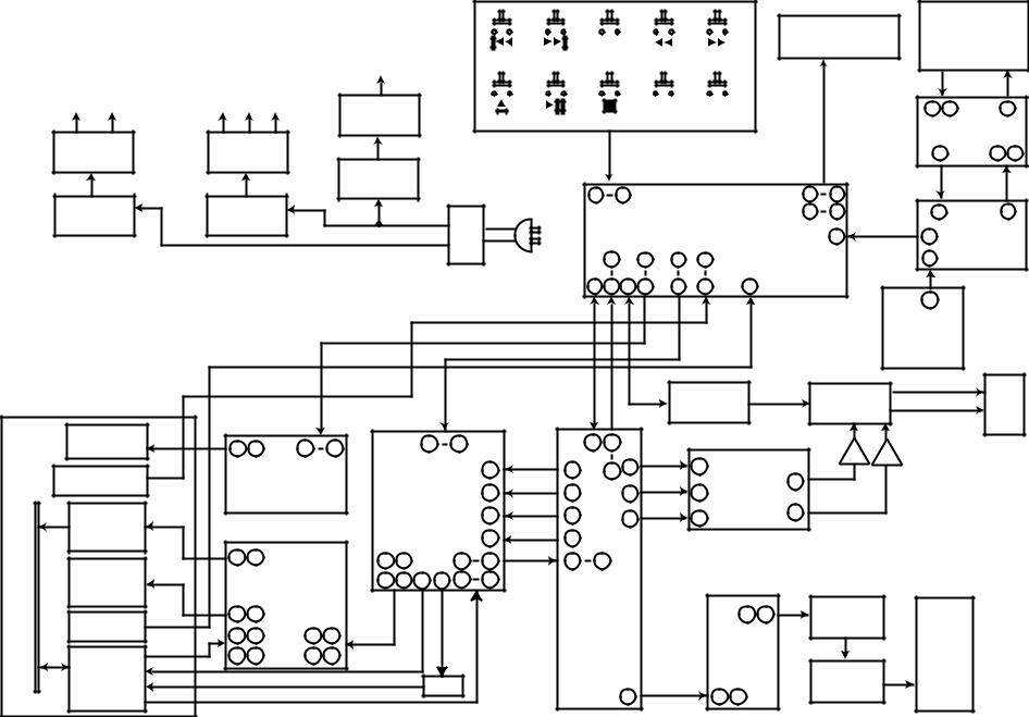
DIAGRAM BLOCK

MAIN BOARD |
TO CHASSIS |
NAD |
IN/OUT |
TRANSFORMER
M502
RED
BROWN
M102 (15 PINS)
M105 (6 PINS)
8
M101 (5 PINS)
BLACK
CD MECHANISM
NEUTRAL |
|
|
|
M505B |
M120A |
LIVE |
|
KEYBOARD |
DISPLAY BOARD |
M505A |
|
DIAGRAM WIRING
LIVE BOARD

RF PATTERN TESTING
Testing |
Point |
J334 |
Testing Point |
R132 |
NAD - C 541 PCB TESTING POINTS DIAGRAM
TESTING PROCEDURE
(1)Load the test disc (Sony Test CD YEDS-7) and set the unit into PLAY mode.
(2)Connect the scope to R132 (Pin 41 of U101) and DGND (J334).
Scope setting: |
Coupling |
: AC. |
|
|
Vertical sensitivity |
: 0.2 |
V/ div. |
|
Horizontal time base |
: 0.5 |
µS/div. |
(3) Observe the waveform is 2.0V p-p +/-5% and the eye pattern is at its best shape (see FIG. 1).
FIG. 1 (a) |
FIG. 1 (b) Poor eye pattern |
3T 4T 5T — |
11T |
FIG. 1 (C) Good eye pattern
9

IMPORTANT NOTES
INSTRUCTION FOR HANDLING OPTICAL SYSTEM BLOCK PICK-UP
Electrostatic breakdown of the laser diode in the optical system block may occur due to a potential difference caused by electrostatic charge accumulated on clothing, human body, etc. A ground must be provided as follows to prevent any electrostatic charge during unpacking or repair work.
1. Ground for Human Body
Be sure to wear a ground band (1M ohm) that is properly to remove any static electricity that may be charged on the body.
2. Ground for Work Bench
Be sure to place a conductive sheet (1M ohm) or copper plate with proper grounding on the work bench or other surface on which the pick-up is to be placed.
3. Because the static electricity charge on the clothing does not discharge through the body grounding band, do not let clothing to get in contact with the pick-up unit.
INCORRECT |
|
CORRECT |
1.Grounding band
1M ohm
1M ohm
2.Conducttive Sheet or Copper Plate
NOTE: Laser diodes are so susceptible to damage from static electricity that even if a static discharge does not ruin the diode, it can shorten its life or cause it to work improperly.
PRECAUTIONS FOR CHECKING BEAM EMISSION
The laser beam of this unit is focused on the reflecting surface of the objective lens in the optical system block. Therefore, keep your eyes at least 12 inches (30 cm) away from the objective lens when the laser diode is ON.
(Operation Check Method for Laser Diode and Focus Search Function.)
When the POWER switch is turned ON after the chucking plate is removed, observe the objective lens and confirm that the following operations are performed properly.
(The optical system should be at the lead-in area position when it is checked at this time.)
(1)The laser should be at the innermost position after the chucking plate is removed.
(2)The diffused light of the laser beam can be seen when the POWER switch is turned ON.
(3)Vertical (up and down) movement of the ojective lens (2 or 3 times) will take place.
10
 Loading...