

Page 1

Model 293.22 Hydraulic Service Manifold
Product Manual
015-081-100 E be certain.
Page 2

©
2014 MTS Systems Corporation. All rights reserved.
Original Instructions (English): 015-081-100 E
Trademark Information
MTS, be certain., Bionix, ElastomerExpress, FlatTrac, FlexTest, Just In Case, LevelPlus, MTS Criterion,
MTS EM Extend, MTS Insight, MTS Landmark, RPC, ServoSensor, SWIFT, Temposonics, TestWare,
TestWorks are registered trademarks of MTS Systems Corporation within the United States. Acumen,
Advantage, Aero ST, Aero-90, AeroPro, Criterion, CRPC, Echo, Flat-Trac, Landmark, MAST,
MicroProfiler, MPT, MTS Acumen, MTS Echo, MTS Fundamentals, MTS TestSuite, ReNew, SilentFlo,
TempoGuard, TestLine, and Tytron are trademarks of MTS Systems Corporation within the United
States. These trademarks may be registered in other countries. All other trademarks are property of
their respective owners. All other trademarks are property of their respective owners.
Proprietary Software
Software use and license is governed by the MTS End User License Agreement which defines all
rights retained by MTS and granted to the End User. All Software is proprietary, confidential, and
owned by MTS Systems Corporation and cannot be copied, reproduced, disassembled, decompiled,
reverse engineered, or distributed without express written consent of MTS.
Software Verification and Validation
MTS software is developed using established quality practices in accordance with the requirements
detailed in the ISO 9001 standards. Because MTS-authored software is delivered in binary format, it
is not user accessible. This software will not change over time. Many releases are written to be
backwards compatible, creating another form of verification. The status and validity of the MTS operating
software is also checked during system verification and routine calibration of MTS hardware. These
controlled calibration processes compare the final test results after statistical analysis against the
predicted response of the calibration standards. With these established methods, MTS assures its
customers that MTS products meet exacting quality standards when initially installed and will continue
to perform as intended over time.
Manual Part Number—Publication Date—Release
015-081-100 E—March 2014
015-081-100 D—March 2008
015-081-100 C—February 2001
150811-00B—November 1994
Page 3

Table of Contents
Technical Support
How to Get Technical Support.........................................................................................................5
Before You Contact MTS.................................................................................................................5
If You Contact MTS by Phone..........................................................................................................7
Problem Submittal Form in MTS Manuals.......................................................................................8
Preface
Before You Begin.............................................................................................................................9
Documentation Conventions............................................................................................................9
Introduction
About the Hydraulic Service Manifold (HSM).................................................................................14
What You Need to Know.....................................................................................................14
Related Products.................................................................................................................14
Model 293.22 HSM Component Identification...............................................................................15
HSM Fluid Flow..............................................................................................................................19
HSM Filtering.................................................................................................................................19
HSM Pressure Control...................................................................................................................19
About HSM Pilot Pressure.............................................................................................................20
HSM Accumulators........................................................................................................................20
HSM Slow Turn-On........................................................................................................................20
HSM Rapid Pressure Reduction....................................................................................................21
Model 293.22 HSM Hydraulic Schematics.....................................................................................21
Table of Contents
Safety
General Safety Practices: Hydraulic Power Units and Hydraulic Service Manifolds.....................24
Hazard Placard Placement.................................................................................................25
Read all manuals................................................................................................................26
Locate and read hazard placards/labels.............................................................................26
Specimen Temperature Changes.......................................................................................26
Know facility safe procedures.............................................................................................26
Know controls......................................................................................................................26
Have first aid available........................................................................................................26
Know potential crush and pinch points...............................................................................26
Be aware of component movement with hydraulics off.......................................................27
Know electrical hazards......................................................................................................27
Keep bystanders safely away.............................................................................................27
Wear proper clothing...........................................................................................................27
3
Page 4

Table of Contents
Remove flammable fluids....................................................................................................27
Check bolt ratings and torques...........................................................................................27
Practice good housekeeping...............................................................................................28
Protect hoses and cables....................................................................................................28
Provide proper hydraulic fluid filtration................................................................................28
Protect accumulators from moving objects.........................................................................28
Do not exceed the Maximum Supply Pressure...................................................................28
Do not disable safety devices.............................................................................................28
Use appropriately sized fuses.............................................................................................28
Provide adequate lighting....................................................................................................29
Provide means to access out-of-reach components...........................................................29
Wear appropriate personal protection.................................................................................29
Handle chemicals safely ....................................................................................................29
Know system interlocks.......................................................................................................29
Know system limits..............................................................................................................29
Do not disturb sensors .......................................................................................................30
Ensure secure cables..........................................................................................................30
Stay alert ............................................................................................................................30
Contain small leaks ............................................................................................................30
Stay clear of moving equipment/avoid crush points ...........................................................30
Know the causes of unexpected actuator motions ............................................................30
Do not use RF transmitters ................................................................................................31
Know compressed gas hazards..........................................................................................31
Installation
HSM Site Preparation....................................................................................................................34
Model 293.22 HSM Hydraulic Connections...................................................................................34
Model 293.22 HSM Electrical Connections....................................................................................36
System Checks..............................................................................................................................37
Operation
HSM Control..................................................................................................................................40
HSM Pilot Pressure Considerations...............................................................................................40
Model 293.22 HSM Controls and Indicators..................................................................................41
Setting Low Pressure.....................................................................................................................42
Maintenance
Hydromechanical System Precautions..........................................................................................46
Model 293.22 HSM Main Filter Cleaning.......................................................................................46
Model 293.22 HSM Pilot Filter Replacement.................................................................................48
Checking the Accumulators...........................................................................................................49
4
Page 5

Technical Support
How to Get Technical Support
Start with your manuals
The manuals supplied by MTS provide most of the information you need to use and maintain your equipment.
If your equipment includes software, look for online help and README files that contain additional product
information.
Technical support methods
MTS provides a full range of support services after your system is installed. If you have any questions
about a system or product, contact Technical Support in one of the following ways.
Web site
Outside the U.S.
For technical support outside the United States, contact your local sales and service office. For a list of
worldwide sales and service locations and contact information, use the Global MTS link at the MTS web
site:
www.mts.com > Global Presence > Choose a Region
www.mts.com > Contact Us (upper-right corner) > In the Subject field, choose
To escalate a problem; Problem Submittal Form
Worldwide: tech.support@mts.comE-mail
Europe: techsupport.europe@mts.com
Worldwide: 1 800 328 2255 - toll free in U.S.; +1 952 937 4000 - outside U.S.Telephone
Europe: +800 81002 222, International toll free in Europe
Before You Contact MTS
MTS can help you more efficiently if you have the following information available when you contact us for
support.
Know your site number and system number
The site number contains your company number and identifies your equipment type (such as material
testing or simulation). The number is typically written on a label on your equipment before the system
leaves MTS. If you do not know your MTS site number, contact your sales engineer.
Example site number: 571167
Model 293.22 Hydraulic Service Manifold | 5
Page 6

Technical Support
When you have more than one MTS system, the system job number identifies your system. You can find
your job number in your order paperwork.
Example system number: US1.42460
Know information from prior technical assistance
If you have contacted MTS about this problem before, we can recall your file based on the:
• MTS case number
• Name of the person who helped you
Identify the problem
Describe the problem and know the answers to the following questions:
• How long and how often has the problem occurred?
• Can you reproduce the problem?
• Were any hardware or software changes made to the system before the problem started?
• What are the equipment model numbers?
• What is the controller model (if applicable)?
• What is the system configuration?
Know relevant computer information
For a computer problem, have the following information available:
• Manufacturer’s name and model number
• Operating software type and service patch information
• Amount of system memory
• Amount of free space on the hard drive where the application resides
• Current status of hard-drive fragmentation
• Connection status to a corporate network
Know relevant software information
For software application problems, have the following information available:
• The software application’s name, version number, build number, and (if available) software patch
number. This information can typically be found in the About selection in the Help menu.
• The names of other applications on your computer, such as:
— Anti-virus software
— Screen savers
— Keyboard enhancers
— Print spoolers
6 | Model 293.22 Hydraulic Service Manifold
Page 7

Technical Support
— Messaging applications
If You Contact MTS by Phone
A Call Center agent registers your call before connecting you with a technical support specialist. The agent
asks you for your:
• Site number
• Email address
• Name
• Company name
• Company address
• Phone number where you can be reached
If your issue has a case number, please provide that number. A new issue will be assigned a unique case
number.
Identify system type
To enable the Call Center agent to connect you with the most qualified technical support specialist available,
identify your system as one of the following types:
• Electrodynamic material test system
• Electromechanical material test system
• Hydromechanical material test system
• Vehicle test system
• Vehicle component test system
• Aero test system
Be prepared to troubleshoot
Prepare to perform troubleshooting while on the phone:
• Call from a telephone close to the system so that you can implement suggestions made over the phone.
• Have the original operating and application software media available.
• If you are not familiar with all aspects of the equipment operation, have an experienced user nearby to
assist you.
Write down relevant information
In case Technical Support must call you:
• Verify the case number.
Model 293.22 Hydraulic Service Manifold | 7
Page 8

Technical Support
• Record the name of the person who helped you.
• Write down any specific instructions.
After you call
MTS logs and tracks all calls to ensure that you receive assistance for your problem or request. If you
have questions about the status of your problem or have additional information to report, please contact
Technical Support again and provide your original case number.
Problem Submittal Form in MTS Manuals
Use the Problem Submittal Form to communicate problems with your software, hardware, manuals, or
service that are not resolved to your satisfaction through the technical support process. The form includes
check boxes that allow you to indicate the urgency of your problem and your expectation of an acceptable
response time. We guarantee a timely response—your feedback is important to us.
You can access the Problem Submittal Form at www.mts.com > Contact Us (upper-right corner) > In the
Subject field, choose To escalate a problem; Problem Submittal Form
8 | Model 293.22 Hydraulic Service Manifold
Page 9

Preface
Before You Begin
Safety first!
Before you use your MTS product or system, read and understand the safety information provided with
your system. Improper installation, operation, or maintenance can result in hazardous conditions that can
cause severe personal injury or death, or damage to your equipment and specimen. Again, read and
understand the safety information provided with your system before you continue. It is very important that
you remain aware of hazards that apply to your system.
Other MTS manuals
In addition to this manual, you may receive additional manuals in paper or electronic form.
You may also receive an MTS System Documentation CD. It contains an electronic copy of the manuals
that pertain to your test system.
Controller and application software manuals are typically included on the software CD distribution disc(s).
Documentation Conventions
The following paragraphs describe some of the conventions that are used in your MTS manuals.
Hazard conventions
Hazard notices may be embedded in this manual. These notices contain safety information that is specific
to the activity to be performed. Hazard notices immediately precede the step or procedure that may lead
to an associated hazard. Read all hazard notices carefully and follow all directions and recommendations.
Three different levels of hazard notices may appear in your manuals. Following are examples of all three
levels. (for general safety information, see the safety information provided with your system.)
Danger:
Danger notices indicate the presence of a hazard with a high level of risk which, if ignored,
will result in death, severe personal injury, or substantial property damage.
Model 293.22 Hydraulic Service Manifold | 9
Page 10
Preface
Warning:
Warning notices indicate the presence of a hazard with a medium level of risk which, if ignored,
can result in death, severe personal injury, or substantial property damage.
Caution:
Caution notices indicate the presence of a hazard with a low level of risk which, if ignored,
could cause moderate or minor personal injury or equipment damage, or could endanger test
integrity.
Other special text conventions
Important:
Important notices provide information about your system that is essential to its proper
function. While not safety-related, if the important information is ignored, test results may
not be reliable, or your system may not operate properly.
Note:
Notes provide additional information about operating your system or highlight easily
overlooked information.
Recommended:
Recommended notes provide a suggested way to accomplish a task based on what MTS
has found to be most effective.
Tip:
Tips provide helpful information or a hint about how to most efficiently accomplish a task.
Access:
Access provides the route you should follow to a referenced item in the software.
Examples show specific scenarios relating to your product and appear with a shaded
background.
Special terms
The first occurrence of special terms is shown in italics.
Illustrations
Illustrations appear in this manual to clarify text. They are examples only and do not necessarily represent
your actual system configuration, test application, or software.
10 | Model 293.22 Hydraulic Service Manifold
Page 11

Preface
Electronic manual conventions
This manual is available as an electronic document in the Portable Document File (PDF) format. It can be
viewed on any computer that has Adobe Acrobat Reader installed.
Hypertext links
The electronic document has many hypertext links displayed in a blue font. All blue words in the body text,
along with all contents entries and index page numbers, are hypertext links. When you click a hypertext
link, the application jumps to the corresponding topic.
Model 293.22 Hydraulic Service Manifold | 11
Page 12

Page 13

Introduction
Topics:
•
About the Hydraulic Service Manifold (HSM)....................................................................................14
•
Model 293.22 HSM Component Identification...................................................................................15
•
HSM Fluid Flow.................................................................................................................................19
•
HSM Filtering.....................................................................................................................................19
•
HSM Pressure Control.......................................................................................................................19
•
About HSM Pilot Pressure.................................................................................................................20
•
HSM Accumulators............................................................................................................................20
•
HSM Slow Turn-On............................................................................................................................20
•
HSM Rapid Pressure Reduction........................................................................................................21
•
Model 293.22 HSM Hydraulic Schematics........................................................................................21
Model 293.22 Hydraulic Service Manifold | 13
Page 14

Introduction
About the Hydraulic Service Manifold (HSM)
The hydraulic service manifold (HSM), also called the actuator manifold, is a hydraulic component that
controls hydraulic pressure to one work station. The HSM controls are independent of the hydraulic power
unit’s controls. The basic function of the HSM is to provide line pressure regulation.
An HSM contains ports to provide pilot valve filtration, the use of accumulators, and the use of hydraulic
solenoid valves to control the hydraulic pressure to the work station.
The HSM is available with a control voltage of 24 V DC or 115 V AC.
What You Need to Know
This manual assumes that you know how to use your system controller. See the appropriate manual for
information about performing any controller-related step in this manual’s procedures. You are expected
to know how to:
• Turn the system hydraulic pressure on and off.
• Turn the station hydraulic pressure on and off.
Related Products
Each HSM includes the Series 111 Accumulators; see the Series 111 Accumulators Product Information
manual (MTS part number 011-553-304) for any accumulator maintenance procedures.
14 | Model 293.22 Hydraulic Service Manifold
Page 15
Introduction
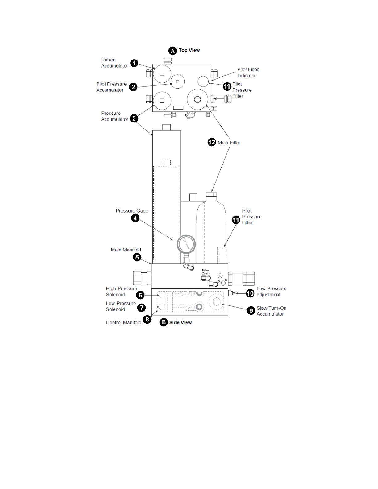
Model 293.22 HSM Component Identification
Model 293.22 Hydraulic Service Manifold
Model 293.22 Hydraulic Service Manifold | 15
Page 16
Introduction
Component Identification Single Channel
16 | Model 293.22 Hydraulic Service Manifold
Page 17

Introduction
Component Identification Multiple Channel
DescriptionNameItem
Viewing angleFront ViewA
Viewing angleSide ViewB
Model 293.22 Hydraulic Service Manifold | 17
Page 18

Introduction
DescriptionNameItem
C
Manifold
Return Accumulator1
2
Pilot Pressure Accumulator
(optional)
Pressure Accumulator3
Main Manifold5
High-Pressure Solenoid Valve6
Low-Pressure Solenoid Valve7
Viewing angleFront View of the Control
Reduces pressure and flow fluctuations resulting from changing
system demands.
Reduces pressure and flow fluctuations at the pilot pressure
port.
Reduces pressure and flow fluctuations resulting from changing
system demands.
Indicates system hydraulic pressure.Pressure Gage4
Distributes hydraulic fluid between the HPU and up to two
control manifolds or a distribution manifold.
Allows high-pressure hydraulic fluid to be output to the hydraulic
channel.
Allows low-pressure hydraulic fluid to be output to the hydraulic
channel.
Control manifold8
Slow Turn-On Accumulator9
Pilot Pressure Filter (optional)11
Main Filter12
Distributes hydraulic fluid to and from a single hydraulic
channel. A hydraulic channel is usually associated with an
actuator and a servovalve. The control manifold also contains
a low-pressure solenoid valve, a high-pressure solenoid valve,
a main valve, a slow turn-on valve, and a pressure gage.
Fills to extend the pressure rise time and slowing the rate at
which the main control valve operates.
Sets the low-pressure output of the hydraulic channel.Low-Pressure Adjustment10
Filters the hydraulic fluid as it is input to the pilot pressure
circuit. The filter has a visual indicator to signal when the
element requires replacement.
Filters the hydraulic fluid as it is input to the main manifold. The
filter has a visual indicator to signal when the element is
requires replacement.
18 | Model 293.22 Hydraulic Service Manifold
Page 19

Introduction
DescriptionNameItem
Pilot Filter Indicator113
Distribution Manifold14
A pop-up indicator is activated when the pilot pressure filter
element becomes dirty.
Distributes hydraulic fluid from the main manifold to up to four
control manifolds.
HSM Fluid Flow
Hydraulic fluid from the HPU enters the HSM at the pressure in port. It passes through an inlet check valve
and a filter. After filtration, part of the fluid is channeled to the pilot pressure circuit. The rest of the fluid
passes through a control manifold, fills the pressure accumulator, passes through the control manifold,
and exits the HSM to an actuator/servovalve through the pressure out port.
Return fluid from the actuator enters the return in port. It flows past the return accumulator and exits to the
HPU through the return out port. Drain ports provide a path for collecting excess fluid and returning it to
the HPU.
HSM Filtering
Fluid passes through the main pressure filter with a wire-mesh cleanable element. An inlet check valve
provides backflow protection for the main filter element when supply pressure drops as the HPU is turned
off. A pilot pressure filter provides 3 μ (absolute) filtration with a visual indicator that shows when the filter
is dirty.
HSM Pressure Control
The control manifold supplies hydraulic pressure to the servovalve and controls whether the pressure is
high or low at the HSM pressure output ports. High-pressure output is typically maintained at 21 MPa
(3000 psi). A gage on the HSM indicates output pressure.
The HSM is in the off-pressure mode when fluid flow is blocked by the main control valve. When low-pressure
solenoid SOL1 is energized, a restricted flow is ported to the slow turn-on accumulator, which begins to
charge. Pressure rises and is applied to the main control valve, causing it to open and port fluid to the
pressure out port. The main control valve opens and closes automatically to maintain the low pressure
level set by the low-pressure adjustment, stabilizing the HSM in low-pressure mode.
1 If you start the pump and hydraulic fluid is cold, the filter indicator may pop out. When this happens: allow
the fluid to warm up, press the filter indicator, and replace the filter element only if the indicator pops out
again.
Model 293.22 Hydraulic Service Manifold | 19
Page 20

Introduction
When high-pressure solenoid SOL2 energizes, pressure in the control circuit rises and is applied to the
main control valve, causing it to open completely and remain open. The HSM is now in high pressure
mode. De-energizing SOL2 allows pressure to bleed off.
The main control valve closes until the low-pressure setting is reached. The HSM is now in low-pressure
mode. De-energizing the low-pressure solenoid disconnects HPS pressure from the control circuit. The
control circuit is now connected to the drain line, and pressure drops rapidly. As control circuit pressure
drops, downstream pressure and a control spring fully close the main control valve. The HSM returns to
the pressure-off mode.
About HSM Pilot Pressure
The HSM is equipped with a hydraulic circuit which provides separately filtered fluid at HPU pressure to
operate the pilot stage of multistage servovalves. This portion of the HSM operates automatically and
requires only routine filter maintenance.
Note:
Turning pressure on and off, or changing between low and high output pressure, does not affect
the pilot pressure output. Pilot pressure is always present, as long as pressure is available from the
HPU. The pilot circuit takes time to bleed down after high pressure is removed from the HSM.
HSM Accumulators
The pressure, return, and pilot pressure accumulators reduce pressure and flow fluctuations caused by
changing system demands. When the HPS is located some distance from the actuator, the flow and
pressure of the hydraulic fluid may be inadequate at certain frequencies.
The type and frequency of the servovalve command signal affects the efficiency of the accumulator. Square
waves cause a greater demand than sine or ramp signals. At low frequencies, fluid flow in the lines can
stop completely and fluid inertia can become an operational factor.
The pressure accumulator reduces the inertia and line restriction considerations. When the servovalve
opens and line pressure begins to drop, the accumulator supplies part of the fluid volume to help maintain
line pressure. Then, when the servovalve closes, the accumulator recharges, causing fluid in the lines to
remain in motion.
An accumulator in the return line reduces pulsing caused by the varying amounts of fluid being discharged
into the lines as the actuator moves. Movement of hoses or "hammering" of hard lines is thus reduced.
HSM Slow Turn-On
The control manifold contains the slow turn-on accumulator. The fixed control circuit inlet orifice, and the
variable low-pressure adjustment orifice affects the rate at which the control circuit operates. When the
low-pressure solenoid is energized, hydraulic fluid is allowed to flow through the control circuit inlet orifice.
20 | Model 293.22 Hydraulic Service Manifold
Page 21

As it passes through the orifice into the control circuit, the initial pressure is decreased substantially. As
the control circuit fills, the slow turn-on accumulator begins to fill, extending the pressure rise time and
slowing the rate at which the main control valve operates. Control circuit bleed-off through the low-pressure
control also increases the time required for the main control valve to balance. A controlled, gradual increase
(or decrease) occurs during the shift from low to high pressure (or from high to low pressure).
HSM Rapid Pressure Reduction
The control manifold dumps hydraulic pressure rapidly when the high and low solenoid valves are
de-energized simultaneously to turn off the fluid flow and port the output pressure line to the return line.
The control circuit is connected to the drain line and pressure in the control circuit drops rapidly, allowing
downstream pressure and a control spring to close the main control valve. HPU pressure is disconnected
from the pressure output. At the same time, the pressure output is connected to the return line by the main
control valve, and the pressure accumulator is drained.
Model 293.22 HSM Hydraulic Schematics
Introduction
The following figures show the hydraulic schematics for the single-channel and multichannel versions of
the HSM.
Single-Channel Hydraulic Schematic
Model 293.22 Hydraulic Service Manifold | 21
Page 22

Introduction
Multi-Channel Hydraulic Schematic
Note:
The Drain Out must be connected to the HPU reservoir or drain circuit.
22 | Model 293.22 Hydraulic Service Manifold
Page 23

Safety
Topics:
•
General Safety Practices: Hydraulic Power Units and Hydraulic Service Manifolds.........................24
Model 293.22 Hydraulic Service Manifold | 23
Page 24

Safety
General Safety Practices: Hydraulic Power Units and Hydraulic Service Manifolds
The hydraulic power unit (HPU) provides high pressure hydraulic fluid to system components for system
operation. The hydraulic service manifold (HSM) controls distribution of that hydraulic fluid pressure. This
section provides general information about safety issues that pertain to system hydraulic supply and
distribution components. These issues include statements to the intended use and foreseeable misuse of
the system and definition for the graphical hazard labeling that is affixed to your product, and other (more
general) safety information that relates to the high-pressure and high-performance characteristics of MTS
servohydraulic and electromechanical systems.
When you prepare to operate a system that includes hydraulic components, ensure the following:
• Do not use or allow personnel to operate the system who are not experienced, trained, or educated in
the inherent dangers associated with high-performance servo hydraulics and who are not experienced,
trained, or educated with regard to the intended operation as it applies to this test system.
• Do not disable safety components or features (including limit detectors, light curtains, or proximity
switches/detectors).
• Do not attempt to operate the system without appropriate personal safety gear (for example, hearing,
hand, and eye protection).
• Do not modify the system or replace system components using parts that are not MTS component parts
or effect repairs using parts or components that are not manufactured to MTS specifications.
• Do not use the system in a test area where uncontrolled access to the test system is allowed when the
system is in operation.
• For servohydraulic systems, do not operate the system unless an interlock is installed to monitor supply
pressure into the HSM and initiate a system interlock if a low or no pressure event occurs.
• Mists of DTE 25 are combustible. Refer to MSDS. Customer is responsible for fire prevention measures
as per facility or building or other local regulations and codes
If you have system related responsibilities (that is, if you are an operator, service engineer, or maintenance
person), you should study safety information carefully before you attempt to perform any test system
procedure.
You should receive training on this system or a similar system to ensure a thorough knowledge of your
equipment and the safety issues that are associated with its use. In addition, you should gain an
understanding of system functions by studying the other manuals supplied with your test system. Contact
MTS for information about the content and dates of training classes that are offered.
It is very important that you study the following safety information to ensure that your facility procedures
and the system’s operating environment do not contribute to or result in a hazardous situation. Remember,
you cannot eliminate all the hazards associated with this system, so you must learn and remain aware of
the hazards that apply to your system at all times. Use these safety guidelines to help learn and identify
hazards so that you can establish appropriate training and operating procedures and acquire appropriate
safety equipment (such as gloves, goggles, and hearing protection).
Each test system operates within a unique environment which includes the following known variables:
24 | Model 293.22 Hydraulic Service Manifold
Page 25

• Facility variables (facility variables include the structure, atmosphere, and utilities)
• Unauthorized customer modifications to the equipment
• Operator experience and specialization
• Test specimens
Because of these variables (and the possibility of others), your system can operate under unforeseen
circumstances that can result in an operating environment with unknown hazards.
Improper installation, operation, or maintenance of your system can result in hazardous conditions that
can cause death, personal injury, or damage to the equipment or to the specimen. Common sense and a
thorough knowledge of the system’s operating capabilities can help to determine an appropriate and safe
approach to its operation.
Hazard Placard Placement
Hazard placards contain specific safety information and are affixed directly to the system so they are plainly
visible.
Each placard describes a system-related hazard. When possible, international symbols (icons) are used
to graphically indicate the type of hazard and the placard label indicates its severity. In some instances,
the placard may contain text that describes the hazard, the potential result if the hazard is ignored, and
general instructions about how to avoid the hazard.
Safety
The following labels are typically located on the HSM.
DescriptionLabel
Warning
Sudden actuator movement can cause severe
personal injury or damage to equipment.
Drain line hose must be connected before applying
pressure to this service manifold.
Part # 048-124-501
Voltage Label
Part # 057-130-001
Voltage Label
Part # 057-130-002
Model 293.22 Hydraulic Service Manifold | 25
Page 26

Safety
Read all manuals
Study the contents of this manual and the other manuals provided with your system before attempting to
perform any system function for the first time. Procedures that seem relatively simple or intuitively obvious
may require a complete understanding of system operation to avoid unsafe or dangerous situations.
Locate and read hazard placards/labels
Find, read, and follow the hazard placard instructions located on the equipment. These placards are placed
strategically on the equipment to call attention to areas such as known crush points, electrical voltage,
and high pressure hazards.
Specimen Temperature Changes
During environmental testing, the specimen temperature can become hot enough to cause burns. Wear
personal protection equipment (gloves) when handling specimens.
Know facility safe procedures
Most facilities have internal procedures and rules regarding safe practices within the facility. Be aware of
these safe practices and incorporate them into your daily operation of the system.
Know controls
Before you operate the system for the first time, make a trial run through the operating procedures with
the power off. Locate all hardware and software controls and know what their functions are and what
adjustments they require. If any control function or operating adjustment is not clear, review the applicable
information until you understand it thoroughly.
Have first aid available
Accidents can happen even when you are careful. Arrange your operator schedules so that a properly
trained person is always close by to render first aid. In addition, ensure that local emergency contact
information is posted clearly and in sight of the system operator.
Know potential crush and pinch points
Be aware of potential crush and pinch points on your system and keep personnel and equipment clear of
these areas.
Remember, when hydraulic power is interrupted on a servohydraulic system, it is likely that stored
accumulator pressure will persist for some time within the system. In addition, it is likely that as stored
energy dissipates, gravity will cause portions of the system to move.
26 | Model 293.22 Hydraulic Service Manifold
Page 27

Be aware of component movement with hydraulics off
The actuator rod can also drift down when hydraulics are turned off hitting anything in its path. This
uncommanded movement is because of oil movement between the pressure/return ports and oil blow by
across the piston hub. Be aware that this can happen and clear the area around the actuator rod when
hydraulics are turned off.
Know electrical hazards
When the system electrical power is turned on, minimize the potential for electrical shock hazards. Wear
clothing and use tools that are properly insulated for electrical work. Avoid contact with exposed wiring or
switch contacts.
Whenever possible, turn off electrical power when you work on or in proximity to any electrical system
component. Observe the same precautions as those given for any other high-voltage machinery.
Make sure that all electrical components are adequately grounded. Grounds must remain connected and
undisturbed at all times.
Keep bystanders safely away
Safety
Keep bystanders at a safe distance from all equipment. Never allow bystanders to touch specimens or
equipment while the test is running.
Wear proper clothing
Do not wear neckties, shop aprons, loose clothing or jewelry, or long hair that could get caught in equipment
and result in an injury. Remove loose clothing or jewelry and restrain long hair.
Remove flammable fluids
Remove flammable fluids from their containers or from components before you install the container or
component. If desired, you can replace the flammable fluid with a non-flammable fluid to maintain the
proper proportion of weight and balance.
Check bolt ratings and torques
To ensure a reliable product, fasteners (such as bolts and tie rods) used in MTS-manufactured systems
are torqued to specific requirements. If a fastener is loosened or the configuration of a component within
the system is modified, refer to information in this product manual to determine the correct fastener, fastener
rating, and torque. Over torquing or under torquing a fastener can create a hazardous situation due to the
high forces and pressures present in MTS test systems.
On rare occasions, a fastener can fail even when it is correctly installed. Failure usually occurs during
torquing, but it can occur several days later. Failure of a fastener can result in a high velocity projectile.
Therefore, it is a good practice to avoid stationing personnel in line with or below assemblies that contain
large or long fasteners.
Model 293.22 Hydraulic Service Manifold | 27
Page 28

Safety
Practice good housekeeping
Keep the floors in the work area clean. Hydraulic fluid that is spilled on any type of floor can result in a
dangerous, slippery surface. Do not leave tools, fixtures, or other items not specific to the test, lying about
on the floor, system, or decking.
Protect hoses and cables
Protect electrical cables from spilled hydraulic fluid and from excessive temperatures that can cause the
cables to harden and eventually fail. Ensure that all cables have appropriate strain relief devices installed
at the cable and near the connector plug. Do not use the connector plug as a strain relief.
Protect all system hoses and cables from sharp or abrasive objects that can cause the hose or cable to
fail. Never walk on hoses or cables or move heavy objects over them. Consider hydraulic distribution
system layout and route hoses and cables away from areas that expose them to possible damage.
Provide proper hydraulic fluid filtration
If the system is equipped with a non-MTS hydraulic power unit, ensure proper filtration to the hydraulic
distribution system and testing components. Particles present in hydraulic fluid and cause erratic or poor
system response.
Protect accumulators from moving objects
Protect accumulators with supports or guards. Do not strike accumulators with moving objects. This could
cause the accumulator(s) to separate from the manifold resulting in equipment damage and personal
injury.
Do not exceed the Maximum Supply Pressure
For hydraulic grips and fixtures. make sure that the hydraulic supply pressure is limited to the maximum
pressure defined by the grip or fixture identification (ID) tag.
Do not disable safety devices
Your system may have active or passive safety devices installed to prevent system operation if the device
indicates an unsafe condition. Do not disable such devices as it may result in unexpected system motion.
Use appropriately sized fuses
Whenever you replace fuses for the system or supply, ensure that you use a fuse that is appropriately
sized and correctly installed. Undersized or oversized fuses can result in cables that overheat and fuses
that explode. Either instance creates a fire hazard.
28 | Model 293.22 Hydraulic Service Manifold
Page 29

Provide adequate lighting
Ensure adequate lighting to minimize the chance of operation errors, equipment damage, and personal
injury. You need to see what you are doing.
Provide means to access out-of-reach components
Make sure you can access system components that might be out of reach while standing on the floor. For
example, ladders or scaffolding might be required to reach load cell connectors on tall load units.
Wear appropriate personal protection
Wear eye protection when you work with high-pressure hydraulic fluid, breakable specimens, or when
anything characteristic to the specimen could break apart.
Wear ear protection when you work near electric motors, pumps, or other devices that generate high noise
levels. Some systems can create sound pressure levels that exceed 70 dbA during operation.
Wear appropriate personal protection equipment (gloves, boots, suits, respirators) whenever you work
with fluids, chemicals, or powders that can irritate or harm the skin, respiratory system, or eyes.
Safety
Handle chemicals safely
Whenever you use or handle chemicals (for example, cleaning fluids, hydraulic fluid, batteries, contaminated
parts, electrical fluids, and maintenance waste), refer to the appropriate MSDS documentation for that
material and determine the appropriate measures and equipment required to handle and use the chemical
safely. Ensure that the chemical is disposed of appropriately.
Know system interlocks
Interlock devices should always be used and properly adjusted. Interlock devices are designed to minimize
the chance of accidental damage to the test specimen or the equipment. Test all interlock devices for
proper operation immediately before a test. Do not disable or bypass any interlock devices as doing so
could allow hydraulic pressure to be applied regardless of the true interlock condition. The Reset/Override
button is a software function that can be used to temporarily override an interlock while attempting to gain
control of the system.
Know system limits
Never rely on system limits such as mechanical limits or software limits to protect you or any personnel.
System limits are designed to minimize the chance of accidental damage to test specimens or to equipment.
Test all limits for proper operation immediately before a test. Always use these limits and adjust them
properly.
Model 293.22 Hydraulic Service Manifold | 29
Page 30

Safety
Do not disturb sensors
Do not bump, wiggle, adjust, disconnect, or otherwise disturb a sensor (such as an accelerometer or
extensometer) or its connecting cable when hydraulic pressure is applied.
Ensure secure cables
Do not change any cable connections when electrical power or hydraulic pressure is applied. If you attempt
to change a cable connection while the system is in operation, an open control loop condition can result.
An open control loop condition can cause a rapid, unexpected system response which can result in severe
personal injury, death, or damage to equipment. Also, ensure that all cables are connected after you make
any changes in the system configuration.
Stay alert
Avoid long periods of work without adequate rest. In addition, avoid long periods of repetitious, unvarying,
or monotonous work because these conditions can contribute to accidents and hazardous situations. If
you are too familiar with the work environment, it is easy to overlook potential hazards that exist in that
environment.
Contain small leaks
Do not use your fingers or hands to stop small leaks in hydraulic or pneumatic hoses. Substantial pressures
can build up, especially if the hole is small. These high pressures can cause the oil or gas to penetrate
your skin, causing painful and dangerously infected wounds. Turn off the hydraulic supply and allow the
hydraulic pressure to dissipate before you remove and replace the hose or any pressurized component.
Stay clear of moving equipment/avoid crush points
Stay clear of mechanical linkages, connecting cables, and hoses that move because you can get pinched,
crushed, tangled, or dragged along with the equipment. High forces generated by the system can pinch,
cut, or crush anything in the path of the equipment and cause serious injury. Stay clear of any potential
crush points. Most test systems can produce sudden, high-force motion. Never assume that your reactions
are fast enough to allow you to escape injury when a system fails.
Know the causes of unexpected actuator motions
The high force and velocity capabilities of MTS actuators can be destructive and dangerous (especially if
actuator motion is unexpected). The most likely causes of unexpected actuator response are operator
error and equipment failure due to damage or abuse (such as broken, cut, or crushed cables and hoses;
shorted wires; overstressed feedback devices; and damaged components within the servocontrol loop).
Eliminate any condition that could cause unexpected actuator motion.
30 | Model 293.22 Hydraulic Service Manifold
Page 31

Do not use RF transmitters
Keep radio frequency (RF) transmitters away from the workstation computers, remote terminals, and
electronics consoles. Intense RF fields can cause erratic operation of the more sensitive circuits in the
system.
Know compressed gas hazards
Some environmental chambers use liquid nitrogen or some inert gas to achieve a required test atmosphere.
Typically these gasses are supplied in pressurized tanks.
Observe the following safety practices when you work with high-pressure air or gases:
• When you charge an accumulator, follow all the charging instructions provided in the appropriate product
information manuals. When precharging accumulators, properly identify the type of gas to be used and
the type of accumulator to be precharged.
• Use only dry-pumped nitrogen to precharge nitrogen-charged accumulators. (Dry-pumped nitrogen
can also be labeled “oil pumped” or “dry water pumped.”) Do not use compressed air or oxygen for
precharging: the temperature increase caused by rapid gas compression can result in highly explosive
conditions when hydraulic fluid is in the presence of oxygen or compressed air.
Safety
• Always follow the recommended bleeding procedures before you remove or disassemble components
that contain pressurized gas. When you bleed a gas or remove a fitting, hose, or component that
contains a gas, remember that many gases cannot support life. Therefore, as the ratio of released gas
to oxygen increases, so does the potential for suffocation.
• Wear appropriate safety devices to protect your hearing. Escaping air or gas can create a noise level
that can damage your hearing.
• Ensure that all pressurized air or gas is bled out of a pneumatic or gas-charged device before you start
to disassemble it. A thorough understanding of the assembly and its pressurized areas is necessary
before you undertake any maintenance. Refer to the appropriate product information for the correct
bleeding procedure.
It may not be obvious or intuitive which bolts or fittings are used to restrain a pressurized area. On
some assemblies, you must remove a cover plate to gain access to the structural bolts. Sometimes, to
protect you from a rapid release of trapped gases, a small port is exposed when you remove this cover
plate. Exposing this port ensures that the gas precharge is fully bled before disassembly. However,
this is not the recommended procedure for bleeding a pneumatic or gas-charged device, because it
can expose you to the dangers of escaping compressed gas and particulates that are expelled from
the chamber or around the seals. Do not assume that cover plates and ports are installed in all the
critical locations.
Consult MTS when in doubt about the safety or reliability of any system-related procedure or modification
that involves devices that contain any type of compressed gas.
Model 293.22 Hydraulic Service Manifold | 31
Page 32

Page 33

Installation
Topics:
•
HSM Site Preparation........................................................................................................................34
•
Model 293.22 HSM Hydraulic Connections.......................................................................................34
•
Model 293.22 HSM Electrical Connections.......................................................................................36
•
System Checks..................................................................................................................................37
Model 293.22 Hydraulic Service Manifold | 33
Page 34

Installation
HSM Site Preparation
Consider the following items for site preparation:
• The HSM must be installed in an area that is protected from extreme temperature and humidity. An
environment with a non-corrosive atmosphere is recommended.
• The HSM must be located as close as possible to the servovalve(s) it supplies. The maximum allowable
distance must take the specific system dynamic flow transient requirements and turn-on/turn-off transient
requirements into account. For assistance in calculating these factors, contact MTS Systems Corporation.
• MTS recommends that you install a shut-off valve and lock-out tag on each HSM to ensure that HPU
pressure is not applied to an HSM being serviced.
• To prevent movement of equipment due to hydraulic line transients, the recommended mounting method
includes anchor bolts set in concrete to a steel framework.
• If you have a multi-channel HSM configuration, MTS recommends that you install a shut-off valve and
lock-out tag on each HSM to ensure that HPU pressure is not applied to an HSM being serviced.
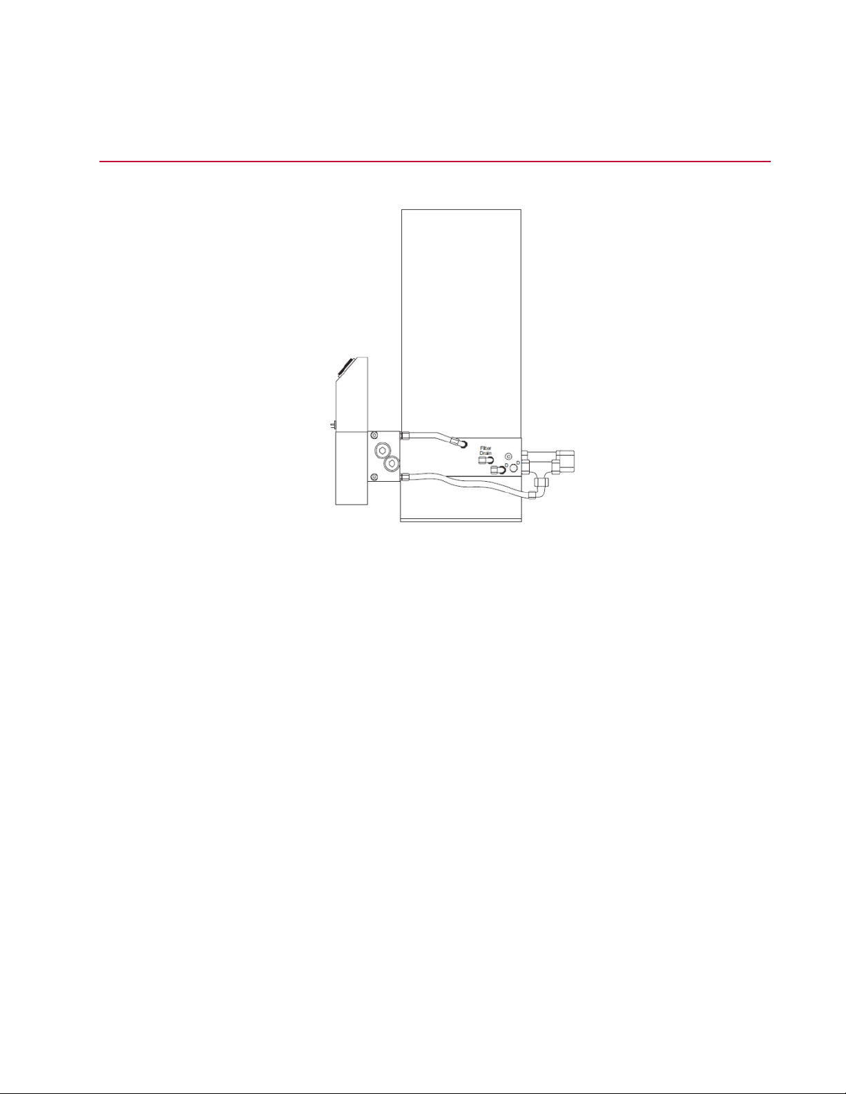
Model 293.22 HSM Hydraulic Connections
For a single-channel HSM, all hydraulic connections are made on the main manifold. In a multichannel
operation, the actuator and servovalve connections are made at the associated control manifold ports; the
HPU connections are made at the main manifold.
34 | Model 293.22 Hydraulic Service Manifold
Page 35

Installation
Note:
Connect the Drain Out line hose to the HPU reservoir or the drain circuit on the hardline before you
apply hydraulic pressure.
Note:
Remove a fluid cap port plug only when a hose is ready for connection. Retain these plugs for use
during service.
Hydraulic Connections
DescriptionItem
PressureP
ReturnR
DrainD
Pilot PressurePP
Pilot Pressure ReturnPR
Hydrostatic BearingHB
Hydrostatic Bearing Supplied PressureHBS
Hydrostatic Bearing Controlled PressureHBC
Model 293.22 Hydraulic Service Manifold | 35
Page 36

Installation
Model 293.22 HSM Electrical Connections
The Model 293.22 HSM is equipped with a control manifold that permits selection of various hydraulic
pressures. Control cable connections must be made between the high and low solenoids of the HSM and
system controller. The following figure shows the locations of the high/low solenoids in both a multichannel
and single-channel HSM.
High/Low Solenoid Locations
DescriptionItem
Low Pressure Solenoid1
High Pressure Solenoid2
Control Manifold (Multi Channel)3
Control Manifold (Single Channel)4
High Pressure Solenoid5
Low Pressure Solenoid6
Depending on the model, the high/low solenoids may be powered by either 115 VAC or 24 VDC. The
following figure shows the pin assignments of each connector.
• The Model 293.22A contains 24 VDC control power. The 3-pin connector for the high/low solenoids is
shown below.
36 | Model 293.22 Hydraulic Service Manifold
Page 37

• The Model 293.22B contains 115 VAC control power. The 3-pin DIN connector for the high/low solenoids
is shown below.
Pin Assignments for High/Low Solenoid Connectors
System Checks
Complete the following steps to ensure proper HSM installation.
1. Check the HSM for secure mounting.
2. Check all hydraulic connections according to the system diagrams. Ensure that the connections are
secure.
3. Check all electrical cable connections (where applicable) according to the system diagrams. Ensure
that the connections are correctly mated and locked.
4. Precharge the accumulators. The procedure for precharging accumulators manufactured by MTS
Systems Corporation can be found in the Series 111 Accumulator Product Information manual. For
accumulators not manufactured by MTS Systems Corporation, refer to the vendor literature for that
accumulator.
5. Check to see if you have installed a shut-off valve and lock-out tag on each HSM to ensure that HPU
pressure is not applied to an HSM being serviced. Remember that pilot pressure is present whenever
there is supply pressure even if the HSM is off.
6. Apply low pressure. Check for leaks at all hose connections and on the HSM. With pressure turned off,
tighten fittings as necessary. Apply high pressure and check again for leaks.
7. Apply high pressure and operate the system for at least ten minutes to bleed air from the system.
8. Check the setting of the low and high pressure output levels. Check the ramp time between low and
high pressure levels.
9. Turn off hydraulic and electrical power.
10. Check the HPU fluid level.
Installation
Model 293.22 Hydraulic Service Manifold | 37
Page 38

Page 39

Operation
Topics:
•
HSM Control......................................................................................................................................40
•
HSM Pilot Pressure Considerations..................................................................................................40
•
Model 293.22 HSM Controls and Indicators......................................................................................41
•
Setting Low Pressure........................................................................................................................42
Model 293.22 Hydraulic Service Manifold | 39
Page 40

Operation
HSM Control
Solenoid control valves located on the HSM control manifold are controlled by the system controller; they
cannot be controlled locally. Low-pressure, high pressure, or pressure-off conditions are operated from
the system controller (which can be controller software, a control panel, or a remote module).
The manifold design requires the HSM to be switched to low pressure from the off condition. This makes
the sequence to obtain a high-hydraulic pressure output, from off to low to high. Pressure is then reduced
by returning to low pressure mode.
Smooth pressure transitions between one mode and another are automatically provided by the HSM.
Pushing the Emergency Stop or Hydraulics Off pressure control switch causes the HSM to turn off input
hydraulic pressure and connect the pressure output to the return line.
HSM Pilot Pressure Considerations
The HSM is equipped with a hydraulic circuit which provides separate filtered fluid at HPU pressure to
operate the pilot stage of multistage servovalves.
Warning:
Pilot pressure is always present, as long as pressure is available from the HPU. Turning HSM
pressure on and off, or changing between low and high output pressure, does not affect the
pilot pressure output.
Disturbing the pilot pressure circuit can cause unexpected actuator movement which can
cause personal injury, damage to equipment, or both.
Ensure that the HPU is turned off before working with the pilot pressure circuit.
40 | Model 293.22 Hydraulic Service Manifold
Page 41

Model 293.22 HSM Controls and Indicators
Operation
Controls and Indicators
DescriptionItem
Pressure Gage1
Control Manifold Multi Channel2
Low Pressure Adjustment3
Top View4
Side View5
Model 293.22 Hydraulic Service Manifold | 41
Page 42

Operation
DescriptionItem
Pilot Filter Indicator26
A pop-up indicator is activated when the pilot pressure filter element becomes
dirty.
Pressure Gage7
A liquid-filled, constant-read pressure gage is connected directly to the output
pressure line. A small orifice protects it against damage from rapid pressure
changes. For single-channel operation, the pressure gage is located on the main
manifold. For multichannel operation, each control manifold contains a pressure
gage.
Low Pressure Adjustment8
A variable orifice is used to set the output pressure of the HSM in the low-pressure
mode For single-channel operation, the low-pressure adjustment is located on
the main manifold. For multichannel operation, each control manifold contains a
low-pressure adjustment.
Control Manifold Single Channel9
Setting Low Pressure
The pressure delivered in high-pressure mode is determined by the HPU output pressure. Refer to the
operation section of the appropriate HPU manual for instructions on setting this level. In low-pressure
mode, the pressure delivered is determined by the setting of the low-pressure adjustment in the HSM.
Refer to the appropriate section for the location of the low-pressure adjustment. The setting can be changed
by using the following procedure.
1. Turn the HPU to low pressure.
2. Turn the HPU to high pressure.
3. Activate the HSM in low-pressure mode. Use the HSM pressure gage to check the present low-pressure
setting.
4. While holding the setting of the low-pressure adjustment with a hex key, turn the locking nut 1/2 turn
counterclockwise.
5. Set the pressure to the desired level, as registered on the gage. Clockwise rotation increases pressure.
6. While holding the setting of the low-pressure adjustment with the hex key, tighten the locking nut 1/2
turn clockwise.
7. Check the pressure at the gage. If necessary, repeat Steps 4 through 6 to improve the accuracy of the
setting.
2 If you start the pump and hydraulic fluid is cold, the filter indicator may pop out. When this happens: allow
the fluid to warm up, press the filter indicator, and replace the filter element only if the indicator pops out
again.
42 | Model 293.22 Hydraulic Service Manifold
Page 43

8. Turn off the system.
Operation
Model 293.22 Hydraulic Service Manifold | 43
Page 44

Page 45

Maintenance
Topics:
•
Hydromechanical System Precautions..............................................................................................46
•
Model 293.22 HSM Main Filter Cleaning...........................................................................................46
•
Model 293.22 HSM Pilot Filter Replacement....................................................................................48
•
Checking the Accumulators...............................................................................................................49
Model 293.22 Hydraulic Service Manifold | 45
Page 46

Maintenance
Hydromechanical System Precautions
Hydraulic systems have the capacity for rapid and forceful movement. Systems contain equipment that
can be hazardous to persons and damaging to equipment, if improperly used.
Warning:
Do not perform calibration, maintenance, or repair procedures with the hydraulic system
operating.
This can cause injury to persons or damage to equipment or both (due to unexpected actuator
movement).
Ensure that you read the following precautions.
Follow these precautions:
• Do not permit untrained people to operate, or service the system.
• Ensure that the Hydraulic Power Unit (HPU) is turned off before you service or go near hydraulic
equipment. When servicing multi-channel HSMs, MTS recommends that you install a shut-off valve
and lock-out tag on each HSM to ensure that HPU pressure is not applied to the HSM being serviced.
• Remove from the test area all devices which can be damaged by full force, rate, distance, or rotational
movement of the actuator.
• Hydraulic system fluids can be irritating to skin and eyes and are poisonous if taken internally.
• Hydraulic systems operate at high pressures and the spray from even a small leak can cause cutting
or piercing injuries. If possible, test new equipment at low pressure and only when no one is near the
system.
• Use only specified parts for replacement. Replacement parts found in hardware stores are not suitable
for HSM maintenance and may rupture explosively when pressurized. Contact your MTS service
representative or MTS Systems Corporation for part numbers.
Model 293.22 HSM Main Filter Cleaning
The main filter is a metal screen, mesh-type filter which should be removed and cleaned (or replaced if
damaged) at six-month intervals.
The replacement filter kit is MTS part number 052-957-801. It includes a 74 µ (absolute) filter and a seal
for the filter bowl.
46 | Model 293.22 Hydraulic Service Manifold
Page 47

Warning:
The rapid expansion of pressurized gas can propel objects and generate concussive forces.
The spray of pressurized fluid can be hot and piercing. With pressure supplies turned off,
residual pressure in the system can cause machinery to move.
Pressurized gas and pressurized fluid can result in injury or death.
Unless required for a procedure, turn off hydraulic, pneumatic, and water supply to the system
before performing maintenance. Isolate the system from the supply sources. Make sure that
all of the associated pressure gages read zero (0).
1. Turn off the HPU or remove hydraulic pressure from the hydraulic input of the HSM.
2. Place a drain pan under the filter drain port and remove the cap from the port.
3. Remove the vent plug from the filter bowl. Allow the fluid to drain for five minutes.
4. Unscrew the filter top and remove it.
Caution:
Contaminated hydraulic fluid can collect inside a filter housing around the base of the filter
element.
Maintenance
If contaminated fluid gets into the system supply lines, erratic system operation can result
due to contamination of the system servovalves.
Do not remove a filter element from its housing without first removing all contaminated fluid
from around the base of the element. Make sure that the area around the base of the filter
element is free of contaminated fluid before removing the element.
5. Check the filter bowl for contamination (particles adhering to the inside of the bowl). If contamination
is present, check the system for wear or loss of seal integrity. Wipe the bowl out with a lint-free cloth.
6. Carefully clean all contaminated fluid from around the base of the filter element.
7. Remove the filter element and inspect it for physical damage. If it is damaged, replace it and proceed
to step 14.
Note:
Ultrasonic cleaning is the preferred method for cleaning the filter. The cleaning and rinsing
solutions may be obtained from MTS as part numbers 111617-01 and 111617-02, respectively.
If an ultrasonic unit is not available, these solutions can be used with a plastic bristle brush for
manual cleaning.
8. Fill the ultrasonic unit tank with approximately 130 mm (5 in) of water and allow it to warm up for 10
minutes.
9. Obtain a plastic container with sufficient volume to entirely submerge the element and small enough
to stand in the ultrasonic unit. Fill it with cleaning solution.
10. After removing any rubber components, such as the ring seal, from the element, place it in the container
and agitate it by hand for two minutes.
11. Remove it and apply pressurized air to remove large particles.
Model 293.22 Hydraulic Service Manifold | 47
Page 48

Maintenance
12. Stand the container in the ultrasonic unit tank and submerge the element in the container for at least
five minutes. Allow additional time if the element is exceptionally dirty.
13. Remove the element from the container. Apply compressed air to the element to remove fluid and dirt.
14. Empty, rinse, and refill the container with cleaning solution.
15. Repeat Step 12 and Step 13. Inspect the element. If contamination is still present, repeat Steps 12
through 14 until it is clean, or discard the element and replace it. If replaced, proceed to Step 17.
16. Empty the container. Rinse and fill it with rinsing solution. Repeat Step 12 and Step 13.
17. Replace the filter bowl seal. Install the element on the manifold. Ensure that the filter bowl seal is seated
in its channel.
18. Screw the filter bowl into place until it is seated. Tighten it to 40.7 N•m (30 lb•ft).
19. Empty the drain pan. Replace the cap on the drain port fitting.
20. Replace the vent plug. Tighten it to 47.5 N•m (35 lb•ft).
21. Test the system after you have finished:
a) Apply low pressure and check the filter bowl and drain port for leaks.
b) Switch to high pressure and check the filter bowl, vent plug, and drain port for leaks.
c) To tighten components, remove pressure.
d) Repeat pressure checks until leakage is stopped.
Model 293.22 HSM Pilot Filter Replacement
Replace the filter element if the indicator pops out. If fluid is cold when you start the pump, the pilot pressure
indicator may pop out. Let the fluid warm up, press the indicator in, and replace the filter element if it pops
out again.
Fluid filtration is provided by a 3 µ (absolute) pilot pressure filter. The replacement filter kit is MTS part
number 052-957-701. The kit includes a 3 µ (absolute) pilot pressure filter, an O-ring filter bowl seal, and
a back-up retainer ring. The MTS part number for the filter element only is 010-088-309.
Warning:
Pilot pressure is always present as long as pressure is available from the HPU. With the HPU
off, residual pressure can still exist in hydraulic systems.
Opening a hydraulic line or component that contains pilot or residual pressure can cause
sudden, unexpected pressure release resulting in injury to personnel or damage to equipment.
Before you compromise a hydraulic line or component, make sure that the HPU is turned off
and the residual pressure is zero. To bleed a circuit to zero requires that you bleed the circuit
at the accumulator valve or wait a minimum of twenty minutes after the HPU has been turned
off.
1. Turn off the HPU or remove hydraulic pressure from the hydraulic input of the HSM.
2. Place a drain pan under the filter drain port and remove the cap from the port.
3. Remove the vent plug from the filter bowl. Allow the fluid to drain for five minutes.
4. Manually turn the filter bowl counterclockwise (when viewed from above) to remove it.
5. Remove the filter element and discard it.
48 | Model 293.22 Hydraulic Service Manifold
Page 49

Maintenance
6. Wipe the filter base dry with a clean, lint-free cloth and visually check the main seal and back-up ring
for damage. If necessary, replace them with new seals from the pilot filter kit.
7. Check the filter bowl for signs of contamination (particles adhering to the inside of the bowl). If
contamination is present, check the system for wear or loss of seal integrity.
Warning:
Re-using a dirty filter can introduce contamination.
Contaminated hydraulic fluid can cause premature wear of the hydraulic components in
your system.
Do not re-use filter elements.
8. With a small amount of clean hydraulic fluid, lubricate the main seal, back-up ring, and internal seal of
a new pilot pressure filter.
9. Install the new filter element and turn the bowl clockwise until it is hand tight.
10. Reset the pilot filter indicator by pressing it down.
11. Remove and empty the drain pan. Replace the cap on the drain port fitting. Replace the vent plug.
Tighten it to 47.5 N•m 35 lb•ft).
12. Remove any specimen from the test area and turn on electrical power.
13. Activate the HPU in low and then high pressure mode.
14. Operate the actuator for at least five minutes to bleed any air from the pilot circuit(s).
Checking the Accumulators
The accumulators have a pressure charge of compressed gas. The accumulator’s correct precharge
pressures are recorded on their labels. The precharge pressure should be checked once a month.
Warning:
Do not charge the accumulators with gases other than pure (commercial grade, dry) nitrogen
gas.
Using unacceptable gasses can cause personal injury, damage to equipment, or both.
Refer to the accumulator manual for information about charging the accumulator.
The recommended accumulator precharge levels for an HPU output of 21 MPa (3000 psi) are as follows:
PrechargeAccumulator
7 MPa (1000 psi)3Main pressure
3 May be varied according to system performance.
Model 293.22 Hydraulic Service Manifold | 49
Page 50

Maintenance
PrechargeAccumulator
0.35 MPa (50 psi)4Return
7 MPa (1000 psi)Pilot pressure
1.4 MPa (200 psi)Slow turn-on
Record both the pressure and the room temperature in a log book. Use these readings as a basis for
changing the interval between pressure checks. Initially, check the precharge after two weeks or 100
operating hours:
• If there is a change of ±1.4 MPa (±200 psi) or more in the pressure line accumulator, check the precharge
every week or 50 operating hours.
• If there is a change of less than ±1.4 MPa (±200 psi) in the pressure line accumulator, check the
precharge every four weeks or 200 operating hours.
• If there is a ±50% or more change in the return, pilot pressure, or slow turn-on accumulators, check
the precharge every week or 50 operating hours.
• If there is a change of less than ±50% in the return, pilot pressure, or slow turn-on accumulators, check
the precharge every four weeks or 200 operating hours.
See the Series 111 Accumulator Product Information manual (MTS part number 011-553-304) for
maintenance procedures.
4 For optimum performance, set the precharge within this range as close as possible to the low-pressure
setting (2.8 MPa; 400 psi minimum).
50 | Model 293.22 Hydraulic Service Manifold
Page 51

Page 52

MTS Systems Corporation
14000 Technology Drive
Eden Prairie, Minnesota 55344-2290 USA
Toll Free Phone: 800-328-2255
(within U.S. or Canada)
Phone:952-937-4000
(outside the U.S. or Canada)
Fax 952-937-4515
E-mail: info@mts.com
Internet: www.mts.com
ISO 9001 Certified QMS
 Loading...