

Page 1

Model 286.31 Transient Permeability
Pore Pressure Intensifier
Product Information
l
015-018-201 C
Page 2

Copyright information © 2007 MTS Systems Corporation. All rights reserved.
Trademark information MTS is a registered trademark of MTS Systems Corporation.
Contact information MTS Systems Corporation
14000 Technology Drive
Eden Prairie, Minnesota 55344-2290 USA
Toll Free Phone: 800-328-2255 (within the U.S. or Canada)
Phone: 952-937-4000 (outside the U.S. or Canada)
Fax: 952-937-4515
E-mail: info@mts.com
http://www.mts.com
Publication information
Manual Part Number Publication Date
015-018-201 B
015-018-201 C
July 1992
August 2007
Page 3

Contents
Introduction 5
Major Components 6
Control Panel Valves 7
Specifications 9
How the Pressure Intensifier Works 10
The Area Ratio 11
Operation 13
Operating the Control Panel Valves 15
Purging and Filling the Fluid Lines 16
Fill the Fluid Reservoir 17
Purge and Fill the Pressure Intensifier 20
Pressurize the Intensifier 22
Purge and Fill the Lower Pore Line 24
Purge and Fill the Reference Volume 1 Lines 26
Purge and Fill the Balance and Upper Pore Lines 29
Purge and Fill the Reference Volume 2 Lines 32
Purge and Fill the Low Pressure Reservoir Line 35
Purge and Fill the Reservoir Return Line 38
Refill the Pressure Intensifier 41
Running a Steady State Flow Test 44
Fill the Pressure Intensifier 45
Purge and Fill the Pore Pressure Lines 49
Refill the Pressure Intensifier 53
Prepare to Run a Test 56
End the Test 58
Running a Transient Permeability Flow Test 59
Fill the Pressure Intensifier 60
Purge and Fill the Pore Pressure Lines 63
Refill the Pressure Intensifier 67
\Prepare to Run the Test 70
End the Test 77
Maintenance 81
286.31 Transient Permeability Pore Pressure Intensifier
3
Page 4

4
286.31 Transient Permeability Pore Pressure Intensifier
Page 5
Introduction
This manual documents the Model 286.31 Transient Permeability Pore Pressure
Intensifier.
The 286.31 pressurizes fresh, distilled water up to 10,000 psi (69 MPa). The
pressurized fluid is applied to a specimen installed in a triaxial cell to test its
permeability characteristics.
286.31 Transient Permeability Pore Pressure Intensifier Introduction
5
Page 6
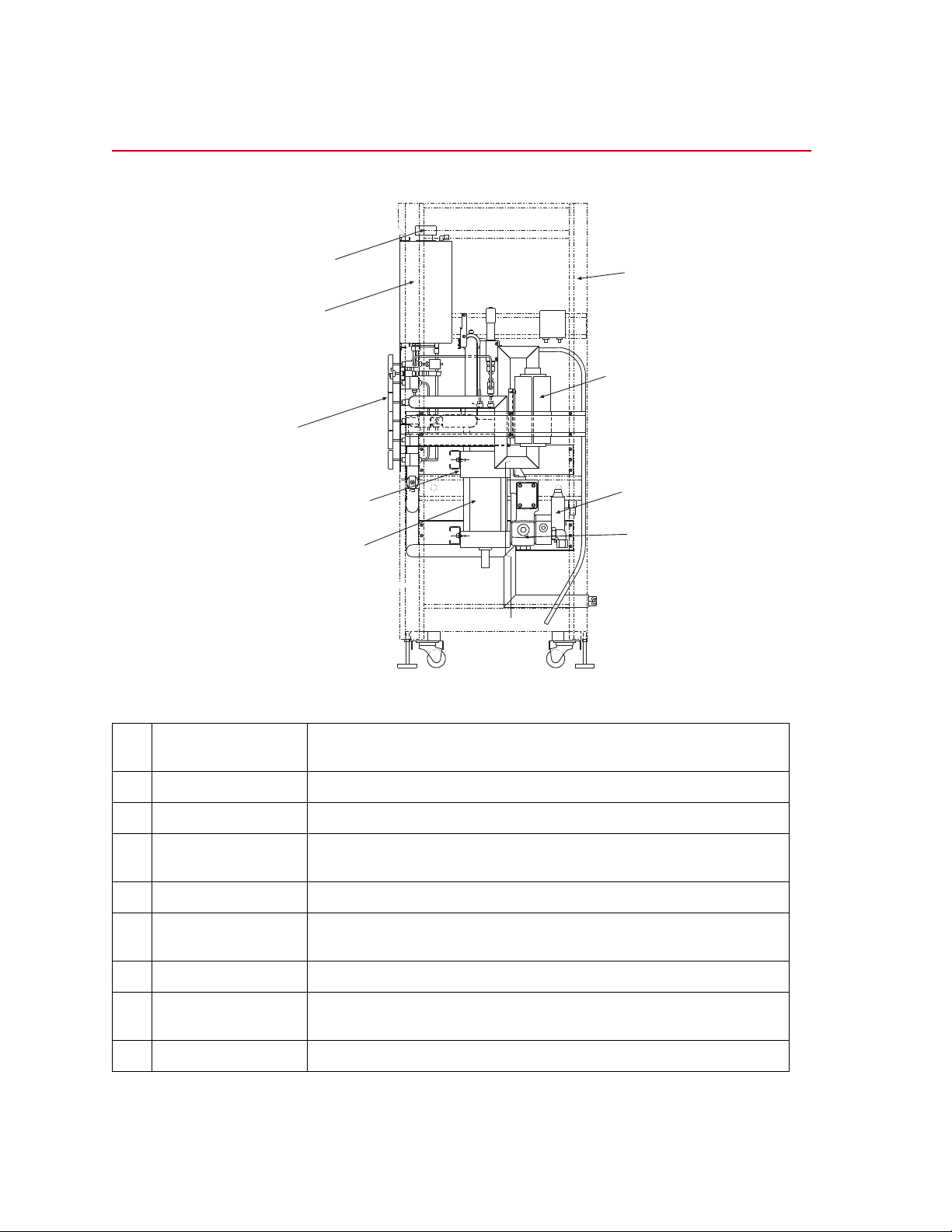
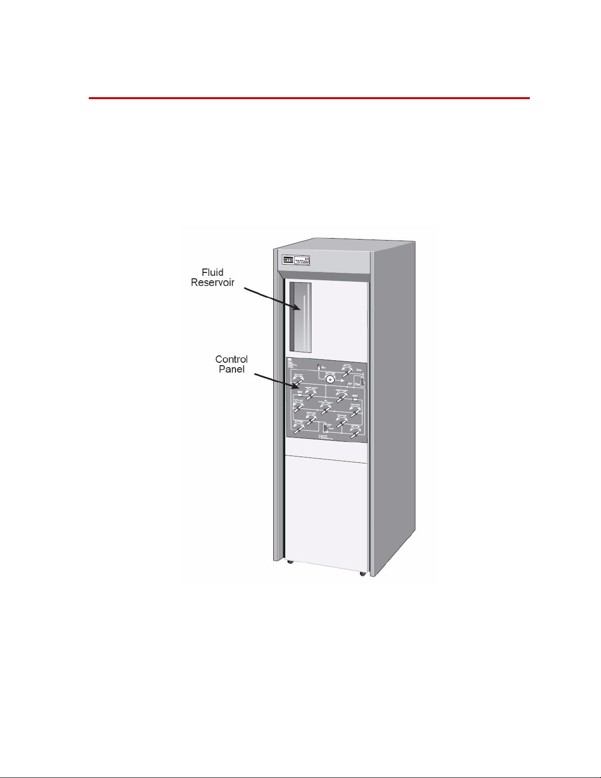
Major Components
1
2
3
4
5
6
7
8
9
Major Components
vent
1
is a removable cap that allows air trapped in the system to escape; also the
fill point for manually filling the reservoir.
cabinet
2
fluid reservoir
3
control panel
4
identification label
5
pressure intensifier
6
actuator manifold
7
servovalve
8
houses the 286.31. It has leveling casters and a rear access door.
holds the system’s distilled water in a clear acrylic container.
has the valves needed to operate the 286.31. Valves are identified by name
and placed in front of a hydraulic schematic of the 286.31 and T riaxial Cell.
lists unit specifications such as pressure, reservoir capacity, and fluid type.
is an servovalve controlled actuator that operates a pump which boosts pore
pressure fluid up to 10,000 psi (69 MPa).
is the connection point for hydraulic components.
responds to system control signals to operate the pressure intensifier’s
piston.
reference volumes
9
6
Introduction
are two high pressure reservoirs used during transient permeability tests.
286.31 Transient Permeability Pore Pressure Intensifier
Page 7
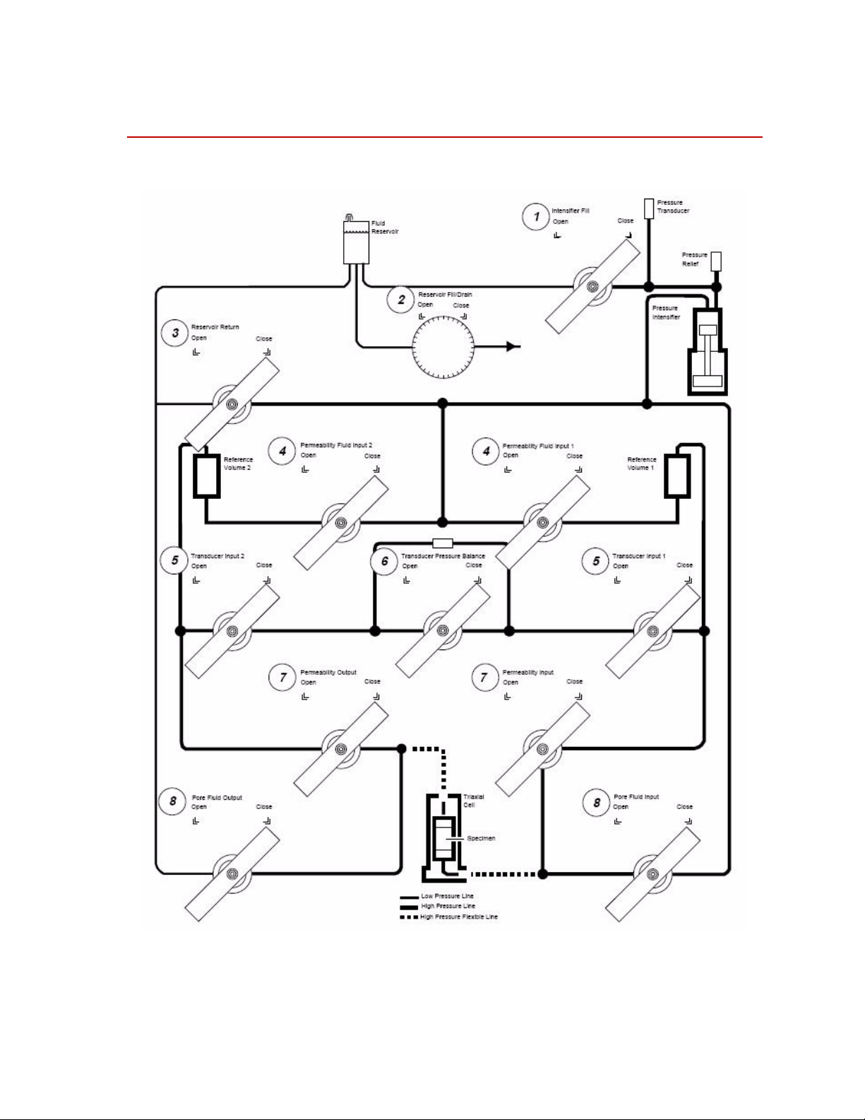
Control Panel Valves
Control Panel Valves
286.31 Transient Permeability Pore Pressure Intensifier Introduction
7
Page 8

Control Panel Valves
1 Intensifier Fill
2 Reservoir Fill/Drain
3 Reservoir Return
4 Permeability Fluid Input 1
Permeability Fluid Input 2
5 Transducer Input 1 Transducer
Input 2
6 Transducer Pressure Balance
7 Permeability Input Permeability
Output
8 Pore Fluid Input Pore Fluid
Output
controls the flow of fluid from the Reservoir into the Pressure
Intensifier.
controls the flow of fluid into the Fluid Reservoir when the 286.31 is
connected to a fluid supply.
is normally kept closed.
control the filling and pressurization of Reference Volumes 1 and 2.
apply Reference Volume 1 and 2 pressures to the Pressure Transducer
when open.
protect the pressure transducer from damaging high pressures. It is
normally left open. When closed it exposes this transducer to the
pressure differential between Reference Volumes 1 and 2.
apply Reference Volume 1 and 2 pressures to the specimen in the
triaxial cell when open.
bypass the permeability fluid circuit when open.
8
Introduction
286.31 Transient Permeability Pore Pressure Intensifier
Page 9

Specifications
Console Dimensions
height
width
depth
Weight 1000 lb 454 kg
74 in.
24 in.
32 in
1880 mm
610 mm
813 mm
Specifications
Reservoir capacity
Intensifier capacity
Controllable output pressure 12,000 psi
Max. fluid temperature 167°F 75°C
Fluid type distilled water
Hardline fittings F375C (female)
1.6 gal (369 in
0.09 gal (20 in
20,000 psi
3
) 6.1 litre (6050 cm3)
3
) 0.34 litre (340 cm3)
80 MPa
140 MPa
286.31 Transient Permeability Pore Pressure Intensifier Introduction
9
Page 10
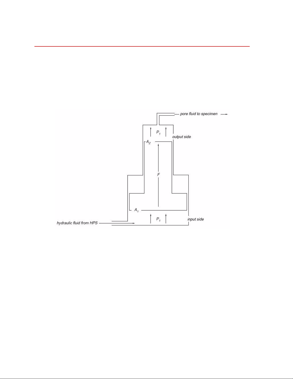
How the Pressure Intensifier Works
FA1P1×=
P
2
F
A
2
------=
How the Pressure Intensifier Works
The 286.31’s Pressure Intensifier develops the 10,000 psi (69 MPa) pressures
applied to your specimen. The pressure transformer is the part of the Intensifier
that develops this pressure.
The pressure transformer’s principle: low pressure applied to a large area
produces a large force. Apply this force over a smaller area and you will produce
a higher pressure.
The hydraulic power supply forces hydraulic fluid into the transformer’s low
pressure input side. The resulting force (F) is the product of the supply side’s
large piston area (A
HPS (P
):
1
) multiplied by the pressure of the hydraulic fluid from the
1
The force produced (F) transfers to the fluid in the output side. The resulting
pressure (P2) is the product of the force (F) divided by the output side’s smaller
piston area (A
Introduction
10
):
2
286.31 Transient Permeability Pore Pressure Intensifier
Page 11

The Area Ratio
area ratio
A
1
A
2
------=
How the Pressure Intensifier Works
The area ratio is the ratio of the input pressure to the output pressure. It
determines how much the input pressure boosts the output pressure. It is
The identification label on your 286.31 gives its area ratio.
For example, your label says the area ratio is 3.33:1. This means a 3000 psi input
pressure will produce a 10,000 psi output pressure.
286.31 Transient Permeability Pore Pressure Intensifier Introduction
11
Page 12

How the Pressure Intensifier Works
12
Introduction
286.31 Transient Permeability Pore Pressure Intensifier
Page 13

Operation
Operation of the 286.31 Intensifier consists of —
• Purging and Filling the Fluid Lines
• Running a Steady State Flow Test
• Running a Transient Permeability Flow Test
Note Complete purging needs only to be done when —
• You first install the 286.31.
• You accidentally draw air into the Pressure Intensifier
Special equipment needed —
• distilled water — at least 2 gallons (8 litres)
• 1% Triton® wetting solution
• Teflon® thread sealing tape
The 286.31 is designed to operate as part of an integrated system that typically
includes —
• a Test Controller with closed-loop control electronics
• a hydraulic power supply
• a triaxial cell or pressure vessel installed in a load unit
• a confining fluid pressure intensifier
T o become familiar with your system, make a trial run of the test you want to run.
Familiarize yourself with the controls and indicators used in each step, without
actually doing the step.
286.31 Transient Permeability Pore Pressure Intensifier Operation
13
Page 14

The following warning, caution, and note apply during all steps.
WARNING
CAUTION
You will be working with very high pressures — The spray from a leak could
cut your skin.
The 286.31 develops intensely high pressures (10000 psi/69 MPa). Broken lines
or fittings could produce a skin cutting spray.
Stop if you can’t build up to test pressure. You may have a leak somewhere.
Reduce pressure to zero, then find and repair the leak.
Fluid hotter than 165°F/75°C can damage the acry lic flui d res erv oi r an d its
hoses.
Watch the temperature of the confining fluid in your triaxial cell —
especially if your cell has heaters. The confining fluid will heat the pore
fluid.
Wait for the confining fluid temperature to cool below 165°F/75°C before
drawing the pore fluid back into the 286.31 reservoir.
Use only distilled water in the 286.31—
Use any other fluid and you can wreck its seals.
Note Adding a 1% T riton wetting solution to the distilled water will lubricate the
286.31’s seals and make them last longer.
14
Operation
286.31 Transient Permeability Pore Pressure Intensifier
Page 15
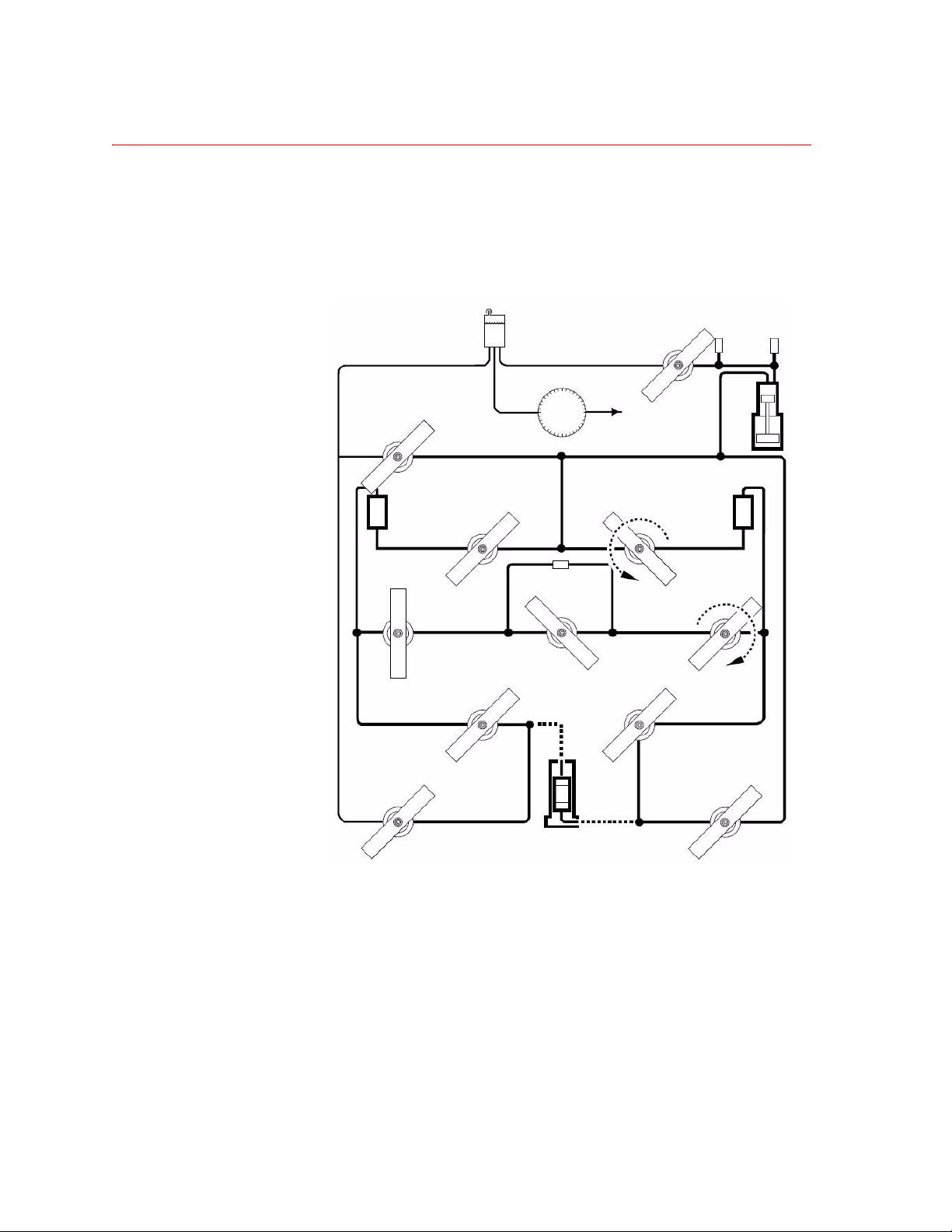
Operating the Control Panel Valves
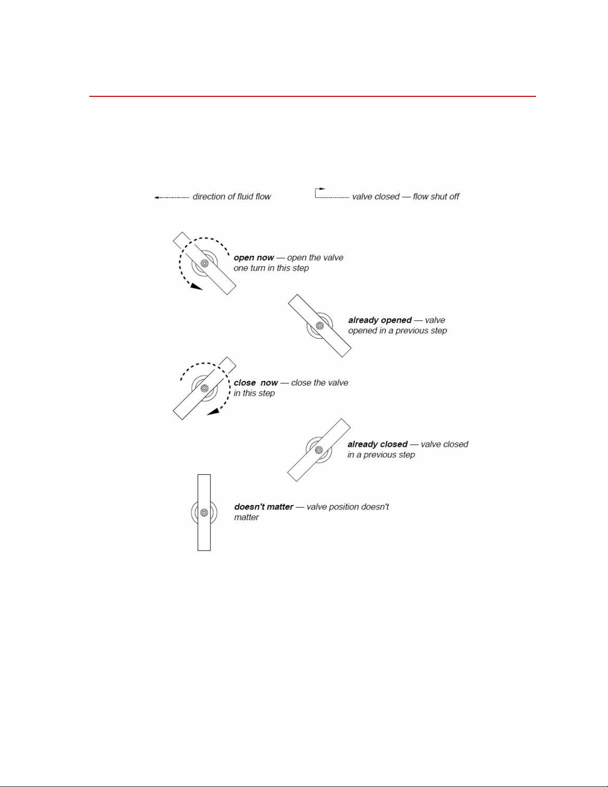
Most of the steps in this section involve opening and closing valves on the
286.31’s control panel. The pictures that follow in this section will show you
which valves to open and close. The figure below is the key to these pictures.
Operating the Control Panel Valves
A full turn opens a valve completely but still lets you shut it quickly. It takes only
light force to shut the valve completely, though using more force won’t hurt it.
286.31 Transient Permeability Pore Pressure Intensifier Operation
15
Page 16

Purging and Filling the Fluid Lines
Purging and Filling the Fluid Lines
In this section you’ll purge the 286.31’s lines of air and fill them with distilled
water.
You only need to do this after installing the 286.31 or if you’ve accidentally
drawn air into the Pressure Intensifier through a dry Fluid Reservoir.
Note Before you start purging and filling, make sure your Triaxial Cell is open.
Purging and filling has ten major tasks, which must be done in order
• Fill the Fluid Reservoir
• Purge and Fill the Pressure Intensifier
• Pressurize the Intensifier
• Purge and Fill the Lower Pore Line
• Purge and Fill the Reference 1 Lines
• Purge and Fill the Balance and Upper Pore Lines
• Purge and Fill the Reference 2 Lines
• Purge and Fill the Low Pressure Reservoir Line
• Purge and Fill the Reservoir Return Line
• Refill the Pressure Intensifier
16
Operation
286.31 Transient Permeability Pore Pressure Intensifier
Page 17
Fill the Fluid Reservoir
CAUTION
An open Transducer Pressure Balance valve protects the differential
pressure transducer from damaging high system pressures —
Keep this valve open except when told to close it.
1. Protect the differential pressure transducer .
Tur n the Transducer Pressure Balance valve to the Open position.
Purging and Filling the Fluid Lines
286.31 Transient Permeability Pore Pressure Intensifier Operation
17
Page 18
Purging and Filling the Fluid Lines
2. If there is a specimen installed in the triaxial cell, remove it. Lines cannot be
purged and filled with a specimen in place.
You will find instructions for removing the specimen in your Triaxial Cell
manual.
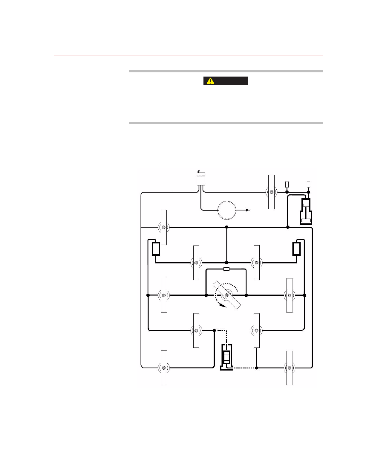
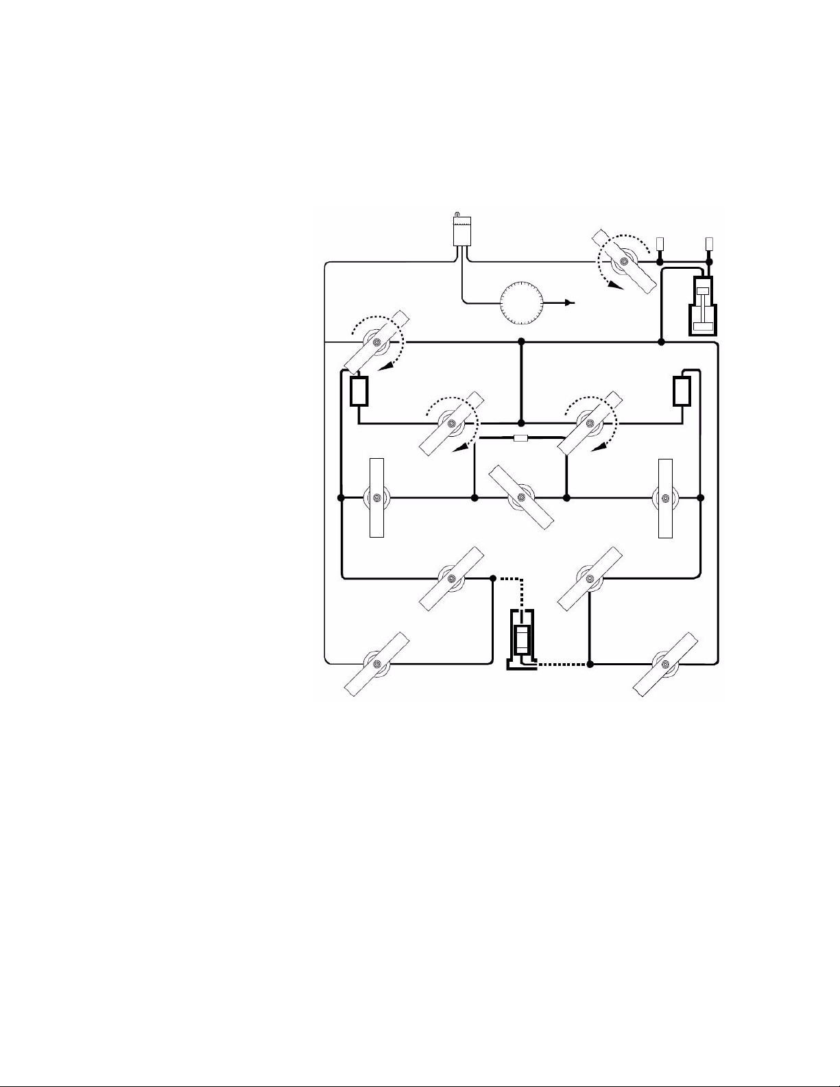
3. Prepare to fill the Fluid Reservoir.
Turn the Pore Fluid Output, Por e Fluid Input, Permeability Output, and
Permeability Input valves to the Close position.
18
Operation
286.31 Transient Permeability Pore Pressure Intensifier
Page 19
Purging and Filling the Fluid Lines
4. Fill the Fluid Reservoir.
If your 286.31 is connected to a distilled water supply —
Tur n the Reservoir Fill/Drain valve to the Open position.
When the Fluid Reservoir is about 3/4 full, turn the Reservoir Fill/
Drain valve to the Close position.
If your 286.31 is not connected to a distilled water supply —
Remove the filler plug at the top of the 286.31’s cabinet.
Open the console’s rear door . Unscrew one of the hex–head plugs in the
Reservoir. (This allows air to vent more easily out of the Reservoir.)
Use a funnel to fill the Fluid Reservoir about 3/4 full.
Seal the filler cap and hex–head plug with Teflon thread sealing tape
and reinstall them.
286.31 Transient Permeability Pore Pressure Intensifier Operation
19
Page 20

Purging and Filling the Fluid Lines
Purge and Fill the Pressure Intensifier
1. Switch on electrical power at the control console.
2. Set up the test controller to control the 286.31’s Pressure Intensifier from the
Manual Control on the RCS (Remote Station Controller).
3. Select the pore pressure control channel’s most sensitive operating range.
4. Select pore pressure as the active control mode.
5. Apply high hydraulic pressure to the 286.31.
20
Operation
286.31 Transient Permeability Pore Pressure Intensifier
Page 21
Purging and Filling the Fluid Lines
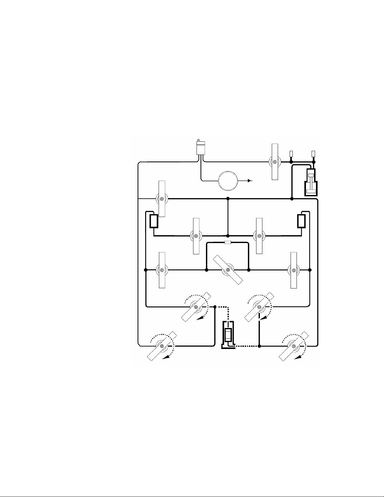
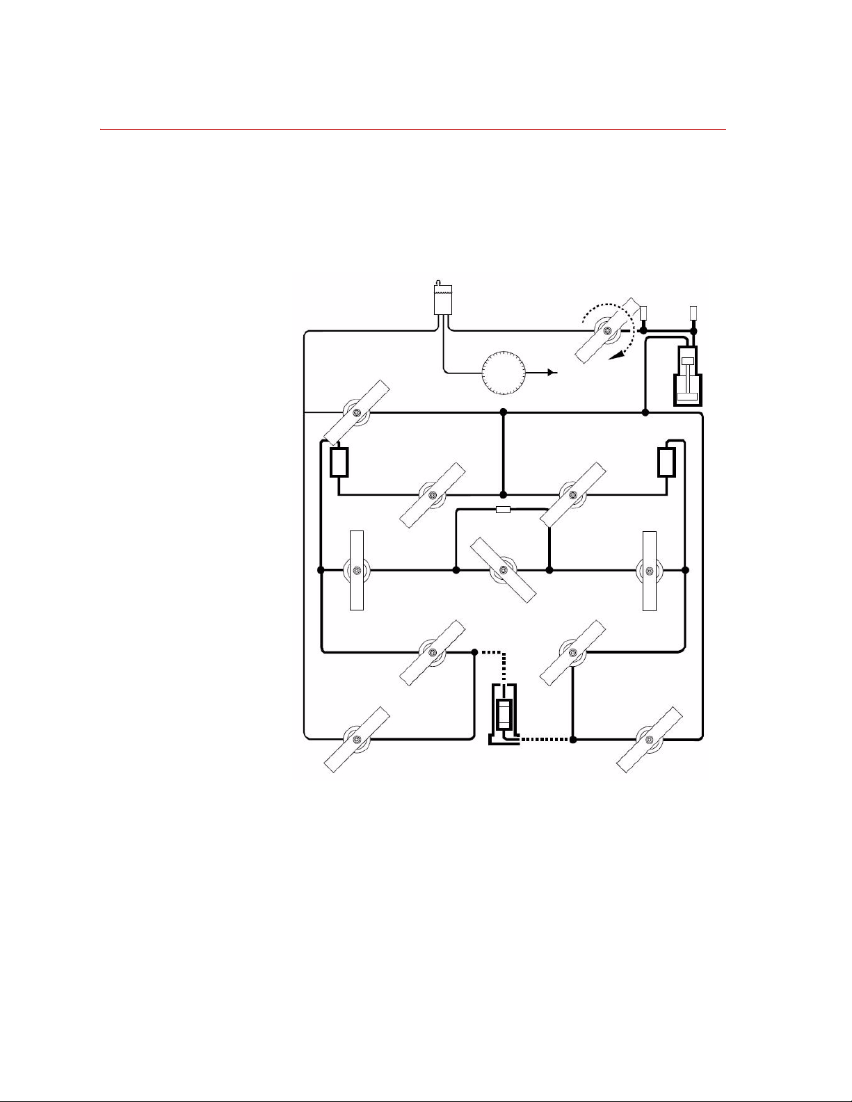
6. Prepare to purge the Pressure Intensifier of air and fill it with fluid.
Tur n the Permeability Fluid Input 1, Permeability Fluid Input 2, and
Reservoir Return valves to the Close position.
Tur n the Intensifier Fill val ve to the Open position.
7. On the test controller, monitor the displacement sensor output.
8. Purge the Pressure Intensifier of air and fill it with fluid.
Slowly turn the Manual Control clockwise, then counterclockwise to fully
stroke the Intensifier’s piston.
Watch the displacement signal to make sure you fully stroke the piston.
When the bubbling at the Fluid Reservoir stops, use the Set Point or
Manual Control to fully retract the Intensifier’s piston.
286.31 Transient Permeability Pore Pressure Intensifier Operation
21
Page 22
Purging and Filling the Fluid Lines
Pressurize the Intensifier
1. On the test controller, monitor the pressure sensor output.
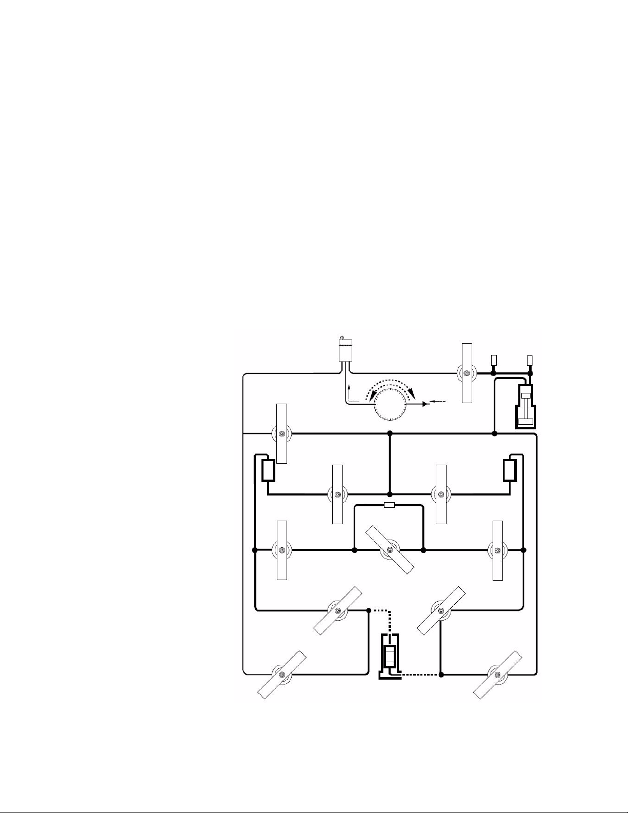
2. Prepare to pressurize the fluid in the 286.31.
Tur n the Intensifier Fill val ve to the Close position.
22
Operation
286.31 Transient Permeability Pore Pressure Intensifier
Page 23

Purging and Filling the Fluid Lines
3. Extend the Pressure Intensifier’s piston to pressurize the fluid.
On the RSC, slowly turn the Manual Control to develop a slight positive
pressure.
While purging, keep the pressure as low as practical but positive all the
time. Keep watching the pore pressure as you purge the lines.
If pressure starts dropping and extending the piston does not raise the
pressure, you will have to stop and refill the Pressure Intensifier.
Note If the Intensifier needs refilling during this procedure —
1. Shut off any valve that is draining fluid out of the 286.31.
2. Turn the Permeability Fluid Input 1, Permeability Fluid Input 2,
and Reservoir Return valves to the Close position.
3. Do the steps in “Refill the Pressure Intensifier” on page 41.
4. Return to the step where you were when the Intensifier ran dry.
5. Turn the Permeability Fluid Input 1, Permeability Fluid Input 2,
and Reservoir Return valves back where they were.
286.31 Transient Permeability Pore Pressure Intensifier Operation
23
Page 24
Purging and Filling the Fluid Lines
Purge and Fill the Lower Pore Line
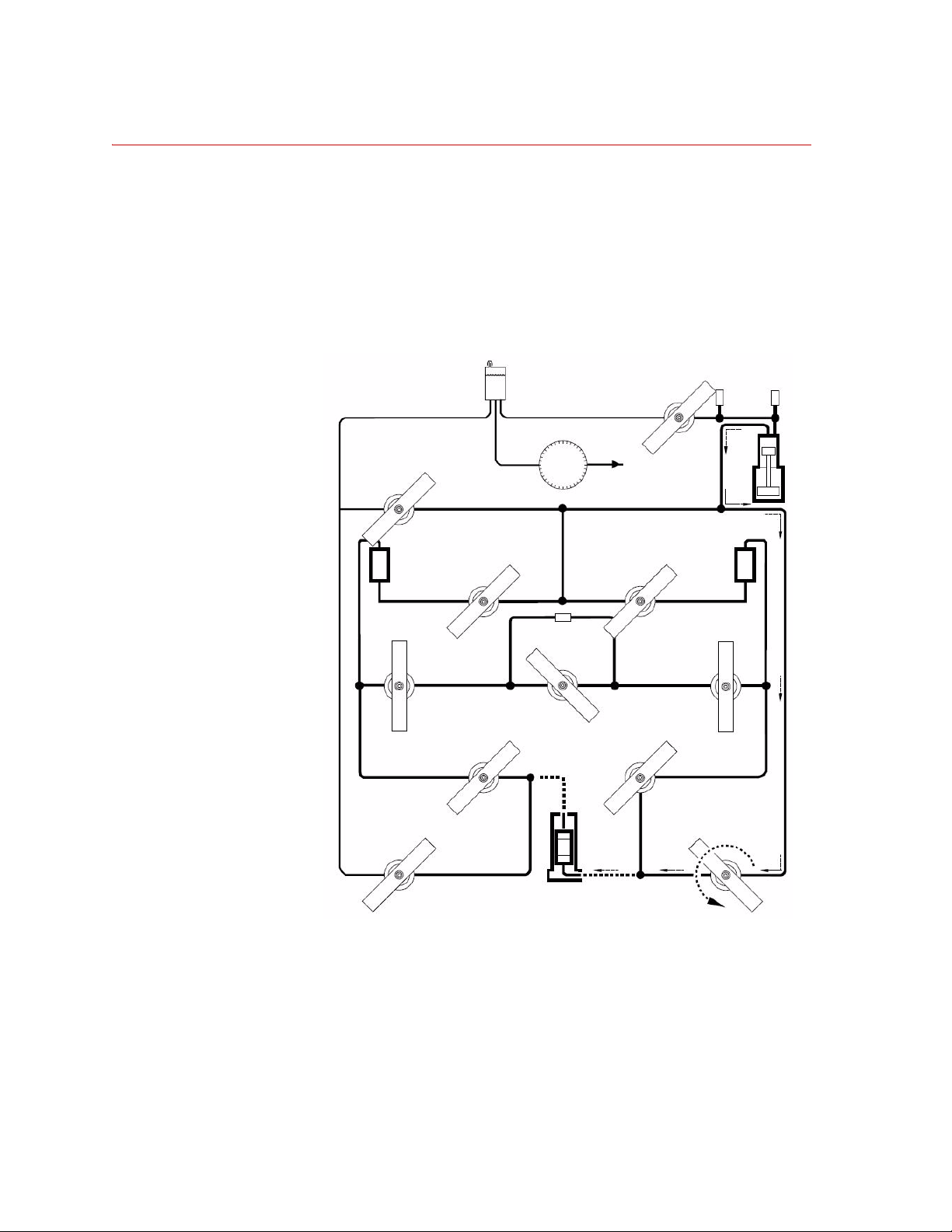
1. Purge the lower pore pressure line of air and fill it with fluid.
Tur n the Pore Fluid Input valve to the Open position.
Fluid and bubbles will come out of the triaxial cell's lower pore pressure
port.
As soon as the bubbles stop, go on to step 2.
24
Operation
286.31 Transient Permeability Pore Pressure Intensifier
Page 25
Purging and Filling the Fluid Lines
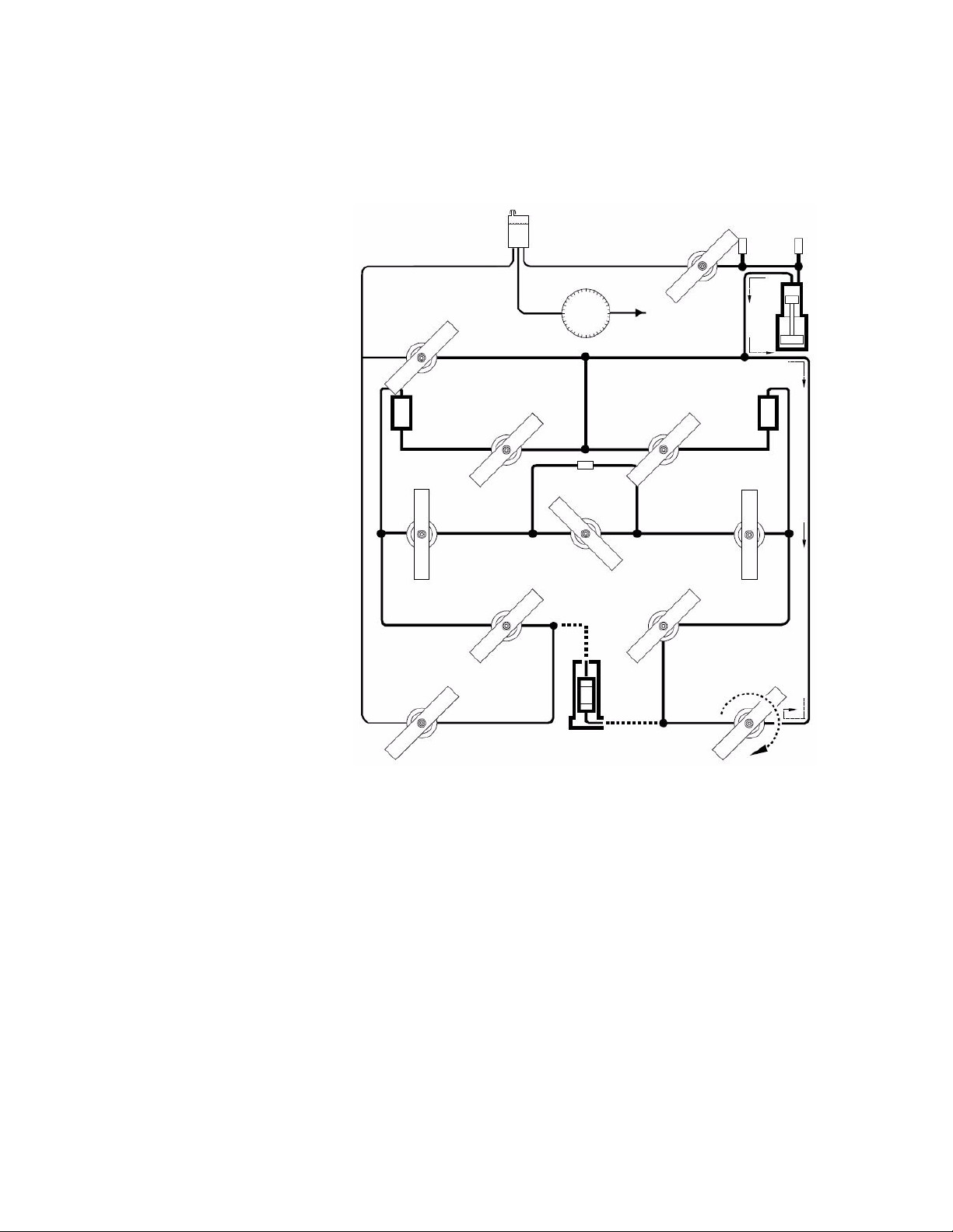
2. Shut off the flow to the triaxial cell.
Tur n the Pore Fluid Input valve to the Close position.
286.31 Transient Permeability Pore Pressure Intensifier Operation
25
Page 26
Purging and Filling the Fluid Lines
Purge and Fill the Reference Volume 1 Lines
1. Prepare to purge the Reference Volume 1 lines of air and fill them with fluid.
Tur n the Permeability Fluid Input 1 valve to the Open position.
Tur n the Transducer Input 1 valve to the Close position.
26
Operation
286.31 Transient Permeability Pore Pressure Intensifier
Page 27

Purging and Filling the Fluid Lines
2. Purge the Reference Volume 1 lines of air and fill them with fluid.
Tur n the Permeability Input valve to the Open position.
As soon as the fluid coming out at the triaxial cell’s lower pore pressure port
becomes bubble-free, go on to step 3.
286.31 Transient Permeability Pore Pressure Intensifier Operation
27
Page 28

Purging and Filling the Fluid Lines
3. Shut off the flow to the triaxial cell.
Tur n the Permeability Input valve to the Close position.
28
Operation
286.31 Transient Permeability Pore Pressure Intensifier
Page 29

Purging and Filling the Fluid Lines
Purge and Fill the Balance and Upper Pore Lines
1. If your triaxial cell has a upper pore pressure valve, open it now.
2. Prepare to purge the Transducer Pressure Balance and upper pore pressure
lines of air and fill them with fluid.
Tur n the Transducer Input 1 and Transducer Input 2 valves to the Open
position.
286.31 Transient Permeability Pore Pressure Intensifier Operation
29
Page 30

Purging and Filling the Fluid Lines
3. Purge the Transducer Pressure Balance and upper pore pressure port lines of
air and fill them with fluid.
Tur n the Permeability Output to the Open position.
As soon as the fluid coming out at the triaxial cell’s upper pore pressure port
becomes bubble-free, go on to step 4.
30
Operation
286.31 Transient Permeability Pore Pressure Intensifier
Page 31

Purging and Filling the Fluid Lines
4. Shut off the fluid flow to the triaxial cell.
Tur n the Permeability Output valve to the Close position.
286.31 Transient Permeability Pore Pressure Intensifier Operation
31
Page 32

Purging and Filling the Fluid Lines
Purge and Fill the Reference Volume 2 Lines
1. Prepare to purge the Reference Volume 2 lines of air and fill them with fluid.
Tur n the Permeability Fluid Input 2 valve to the Open position.
Turn the T ransducer Inpu t 2 and Permeability Fluid Input 1 valves to the
Close position.
32
Operation
286.31 Transient Permeability Pore Pressure Intensifier
Page 33

Purging and Filling the Fluid Lines
2. Purge the Reference Volume 2 lines of air and fill them with fluid.
Tur n the Permeability Output to the Open position.
As soon as bubble-free fluid starts coming out at the triaxial cell’s upper
pore pressure port, go on to step 3.
286.31 Transient Permeability Pore Pressure Intensifier Operation
33
Page 34

Purging and Filling the Fluid Lines
3. Stop the flow to the triaxial cell.
Tur n the Permeability Output valve to the Close position.
34
Operation
4. If your Triaxial Cell has an upper pore pressure valve, close it now.
286.31 Transient Permeability Pore Pressure Intensifier
Page 35

Purging and Filling the Fluid Lines
Purge and Fill the Low Pressure Reservoir Line
1. Prepare to purge the low pressure Fluid Reservoir line of air and fill it with
fluid.
Tur n the Pore Fluid Output valve to the Open position.
Air in this line will come out at the Fluid Reservoir.
286.31 Transient Permeability Pore Pressure Intensifier Operation
35
Page 36

Purging and Filling the Fluid Lines
2. Purge the low pressure Fluid Reservoir line of air and fill it with fluid.
If your triaxial cell doesn’t have a shut off valve for the upper pore pressure
line, plug this line at its triaxial cell output. Cap it or plug it with your finger
(or a helper’s).
Tur n the Permeability Output valve to the Open position.
As soon as the fluid entering the Fluid Reservoir becomes bubble-free, go
on to step 3.
36
Operation
286.31 Transient Permeability Pore Pressure Intensifier
Page 37

Purging and Filling the Fluid Lines
3. Stop the flow to the Fluid Reservoir.
Tur n the Permeability Output valve to the Close position.
4. Uncap the Triaxial Cell’s upper pore pressure line if you have plugged it.
286.31 Transient Permeability Pore Pressure Intensifier Operation
37
Page 38

Purging and Filling the Fluid Lines
Purge and Fill the Reservoir Return Line
1. Prepare to purge the Reservoir Return line of air and fill it with fluid.
Tur n the Pore Fluid Output and Permeability Fl uid Input 2 valves to the
Close position.
Air purged from this line will bubble out at the Fluid Reservoir.
38
Operation
286.31 Transient Permeability Pore Pressure Intensifier
Page 39

Purging and Filling the Fluid Lines
2. Purge the reservoir return line of air and fill it with fluid.
Tur n the Reservoir Return valve to the Open position.
As soon as bubbles stop coming out at the Fluid Reservoir, go on to step 3.
286.31 Transient Permeability Pore Pressure Intensifier Operation
39
Page 40

Purging and Filling the Fluid Lines
3. Stop the flow to the Fluid Reservoir.
Tur n the Reservoir Return valve to the Close position.
40
Operation
286.31 Transient Permeability Pore Pressure Intensifier
Page 41

Refill the Pressure Intensifier
1. On the RSC, turn the Manual Control until pressure drops to zero.
2. On the test controller, monitor the displacement sensor output.
3. Prepare to refill the Pressure Intensifier. Turn the Intensifier Fill valve to
the Open position.
Purging and Filling the Fluid Lines
286.31 Transient Permeability Pore Pressure Intensifier Operation
41
Page 42

Purging and Filling the Fluid Lines
4. Refill the Pressure Intensifier with fluid.
On the RSC, slowly turn the Manual Control to retract the Intensifier’s
piston.
Stop when the displacement signal shows a fully retracted piston.
5. Make sure the Pressure Transducer line is fully purged so air bubbles will
not be forced into the pore lines.
On the RSC, slowly turn the Manual Control to extend the Intensifier’s
piston.
Stop when bubble-free fluid begins flowing back into the Reservoir.
Now turn the Manual Control to fully retract the Intensifier’s piston .
6. On the test controller, monitor the pressure sensor output.
42
Operation
286.31 Transient Permeability Pore Pressure Intensifier
Page 43

Purging and Filling the Fluid Lines
7. Prepare to pressurize the 286.31's lines.
Tur n the Intensifier Fill val ve to the Close position.
8. On the RSC, slowly turn the Manual Control to produce a positive
pressure.
286.31 Transient Permeability Pore Pressure Intensifier Operation
43
Page 44

Running a Steady State Flow Test
Running a Steady State Flow Test
Running a steady state flow test has five major tasks
• Fill the Pressure Intensifier
• Purge and Fill the Pore Pressure Lines
• Refill the Pressure Intensifier
• Prepare to Run the Test
• End the Test
Note If you have just done a complete purge of the 286.31, skip ahead to
“Prepare to Run a Test” on page 56.
44
Operation
286.31 Transient Permeability Pore Pressure Intensifier
Page 45

Fill the Pressure Intensifier
1. If you have a specimen installed in the triaxial cell, remove it now. Your
triaxial cell manual has the details on doing this.
2. Turn the valves to match the positions shown in the Step 3 picture.
3. Skip this step if the Reservoir is already 3/4 full.
Fill the Fluid Reservoir.
If your 286.31 is connected to a distilled water supply —
Tur n the Reservoir Fill/Drain valve to the Open position.
When the Fluid Reservoir is about 3/4 full, turn the Reservoir Fill/
Drain valve to the Close position.
If your 286.31 is not connected to a distilled water supply —
Remove the filler plug at the top of the 286.31.
Open the console’s rear door . Unscrew one of the hex–head plugs in the
Reservoir. (This allows air to vent more easily out of the Reservoir.)
Running a Steady State Flow Test
Use a funnel to fill the Fluid Reservoir about 3/4 full.
Seal the filler cap and hex–head plug with Teflon thread sealing tape
and reinstall them.
286.31 Transient Permeability Pore Pressure Intensifier Operation
45
Page 46

Running a Steady State Flow Test
4. Switch on electrical power at the control console.
5. Set up the test controller to control the 286.31’s Pressure Intensifier from
Manual Control on the RSC.
6. Select pore pressure as the active control mode.
7. Select the pore pressure control channel’s most sensitive operating range.
8. Apply high hydraulic pressure to the 286.31.
9. Prepare to purge the Pressure Intensifier of air and fill it with fluid. Turn the
Intensifier Fill valve to the Open position.
46
Operation
286.31 Transient Permeability Pore Pressure Intensifier
Page 47

Running a Steady State Flow Test
10. On the test controller, monitor the displacement sensor output.
11. Purge the Pressure Intensifier of air and fill it with fluid.
On the RSC, slowly turn the Manual Control clockwise, then
counterclockwise to fully stroke the Intensifier’s piston.
Watch the displacement signal to make sure you fully stroke the piston.
When the bubbling at the Fluid Reservoir stops, use the RSC Manual
Control to fully retract the Intensifier’s piston.
12. On the test controller, monitor the pressure sensor output.
286.31 Transient Permeability Pore Pressure Intensifier Operation
47
Page 48

Running a Steady State Flow Test
13. Prepare to pressurize the fluid in the 286.31. Turn the Intensifier Fill valve
to the Close position.
48
Operation
14. Pressurize the fluid in the 286.31 by extending the Intensifier ’s piston.
On the RSC, slowly turn the Manual Control to develop a positive
pressure.
As you purge the pore pressure lines, keep the pressure low but positive all
the time. Keep an eye on the pressure as you purge the lines.
286.31 Transient Permeability Pore Pressure Intensifier
Page 49

Purge and Fill the Pore Pressure Lines
1. Purge and fill the lower pore pressure line.
Tur n the Pore Fluid Input valve to the Open position.
As soon as bubble-free fluid comes out at the triaxial cell’s lower pore
pressure port, go on to step 2.
Running a Steady State Flow Test
286.31 Transient Permeability Pore Pressure Intensifier Operation
49
Page 50

Running a Steady State Flow Test
2. Shut off the flow of fluid to the triaxial cell.
Tur n the Pore Fluid Input valve to the Close position.
50
Operation
3. If your triaxial cell has an upper pore pressure valve, open it now.
286.31 Transient Permeability Pore Pressure Intensifier
Page 51

Running a Steady State Flow Test
4. Purge and fill the upper pore pressure line.
Tur n the Reservoir Return and Pore Fluid Output valves to the Open
position.
Go on to step 5 as soon as bubble–free fluid comes out of the upper pore
pressure line.
286.31 Transient Permeability Pore Pressure Intensifier Operation
51
Page 52

Running a Steady State Flow Test
5. Turn the Reservoir Return and Pore Fluid Output valves to the Close
position.
52
Operation
286.31 Transient Permeability Pore Pressure Intensifier
Page 53

Refill the Pressure Intensifier
1. Refill the Fluid Reservoir.
You can skip this step if the Reservoir is already 3/4 full.
If your 286.31 is connected to a distilled water supply —
Tur n the Reservoir Fill/Drain valve to the Open position.
When the Fluid Reservoir is about 3/4 full, turn the Reservoir Fill/
Drain valve to the Close position.
If your 286.31 is not connected to a distilled water supply —
Remove the filler plug at the top of the 286.31.
Open the console’s rear door . Unscrew one of the hex–head plugs in the
Reservoir. (This allows air to vent more easily out of the Reservoir.)
Use a funnel to fill the Fluid Reservoir about 3/4 full.
Seal the filler cap and hex–head plug with Teflon thread sealing tape
and reinstall them.
Running a Steady State Flow Test
286.31 Transient Permeability Pore Pressure Intensifier Operation
53
Page 54

Running a Steady State Flow Test
2. On the test controller, monitor the displacement sensor output.
3. Prepare to refill the Pressure Intensifier with fluid. Turn the Intensifier Fill
valve to the Open position.
54
Operation
4. Fill the Pressure Intensifier with fluid.
On the RSC, slowly turn the Manual Control to fully retract the
Intensifier’s piston.
Watch the displacement signal to make sure you have fully retracted the
piston.
286.31 Transient Permeability Pore Pressure Intensifier
Page 55

Running a Steady State Flow Test
5. Prepare to pressurize the fluid in the 286.31.
Tur n the Intensifier Fill val ve to the Close position.
286.31 Transient Permeability Pore Pressure Intensifier Operation
55
Page 56

Running a Steady State Flow Test
CAUTION
Prepare to Run a Test
1. Install your specimen in the triaxial cell.
If pore pressure becomes higher than confining pressure — even for a
second — your specimen will be damaged.
Always keep confining pressure higher than pore pressure.
2. If your Triaxial Cell has an upper pore pressure shut off valve, make sure it’s
3. Apply a confining pressure to the specimen.
For the details on doing this step, see the installation section of your triaxial
cell manual.
open.
Confining pressure must always be higher than the pore pressure.
For the details on doing this step, see the operation section of your confining
pressure intensifier manual.
4. Pressurize the pore fluid to the desired starting pressure.
On the RSC, turn the Manual Control control slowly until you reach the
desired pore pressure.
5. If the rest of your system is ready, start your data acquisition procedure.
56
Operation
286.31 Transient Permeability Pore Pressure Intensifier
Page 57

Running a Steady State Flow Test
6. Begin the steady state flow test
Tur n the Pore Fluid Input and Pore Fluid Output valves to the Open
position.
Fluid will slowly flow through the specimen and into the Fluid Reservoir,
discharging at atmospheric pressure.
286.31 Transient Permeability Pore Pressure Intensifier Operation
57
Page 58

Running a Steady State Flow Test
End the Test
1. On the test controller, monitor the pressure sensor output.
2. Remove pressure from the lines.
On the RSC, turn the Manual Control control slowly until pressure
becomes zero.
3. Isolate the triaxial cell.
Turn the Pore Fluid Output and Pore Fluid Input valves to the Close
position.
58
Operation
4. If your triaxial cell has an upper pore pressure valve, close it.
286.31 Transient Permeability Pore Pressure Intensifier
Page 59

Running a Transient Permeability Flow Test
Running a Transient Permeability Flow Test
Performing a permeability flow test has five major tasks
• Fill the Pressure Intensifier
• Purge and Fill the Pore Pressure Lines
• Refill the Pressure Intensifier
• Prepare to Run the Test
• End the Test
Note If you have just done a complete purge of the 286.31, skip ahead to
Section 2.3.4. It begins on page 2-96.
286.31 Transient Permeability Pore Pressure Intensifier Operation
59
Page 60

Running a Transient Permeability Flow Test
Fill the Pressure Intensifier
1. If you have a specimen installed in the triaxial cell, remove it now. Your
triaxial cell manual has the details on doing this.
2. Turn the valves to match the positions shown in the Step 3 picture.
3. Fill the Fluid Reservoir. Skip this step if the reservoir is 3/4 full.
If your 286.31 is connected to a distilled water supply —
Tur n the Reservoir Fill/Drain valve to the Open position.
When the Fluid Reservoir is about 3/4 full, turn the Reservoir Fill/
Drain valve to the Close position.
If your 286.31 is not connected to a distilled water supply —
Remove the filler plug at the top of the 286.31.
Open the console’s rear door . Unscrew one of the hex–head plugs in the
Reservoir. (This allows air to vent more easily out of the Reservoir.)
Use a funnel to fill the Fluid Reservoir about 3/4 full.
Seal the filler cap and hex–head plug with Teflon thread sealing tape
and reinstall them.
60
Operation
286.31 Transient Permeability Pore Pressure Intensifier
Page 61

Running a Transient Permeability Flow Test
4. Switch on electrical power at the control console.
5. Set up the test controller to control the 286.31’s Pressure Intensifier from the
RSC (Remote Station Controller).
6. Select the pore pressure control channel’s most sensitive operating range.
7. Select pore pressure as the active control mode.
8. Apply high hydraulic pressure to the 286.31.
9. Prepare to purge the Pressure Intensifier of air and fill it with fluid. Turn the
Intensifier Fill valve to the Open position.
10. On the test controller, monitor the displacement sensor output.
286.31 Transient Permeability Pore Pressure Intensifier Operation
61
Page 62

Running a Transient Permeability Flow Test
11. Purge the Pressure Intensifier of air and fill it with fluid.
On the RSC, slowly turn the Manual Control clockwise, then
counterclockwise to fully stroke the Intensifier’s piston.
Watch the displacement signal to make sure you fully stroke the piston.
When the bubbling at the Fluid Reservoir stops, use the Manual Control to
fully retract the Intensifier’s piston.
12. On the test controller, monitor the pressure sensor output.
13. Prepare to pressurize the fluid in the 286.31. Turn the Intensifier Fill valve
to the Close position.
62
Operation
14. Pressurize the fluid in the 286.31 by extending the Intensifier ’s piston.
On the RSC, slowly turn the Manual Control to develop a positive
pressure.
As you purge the pore pressure lines, keep the pressure low but positive all
the time. Keep an eye on the pressure as you purge the lines.
286.31 Transient Permeability Pore Pressure Intensifier
Page 63

Purge and Fill the Pore Pressure Lines
1. Purge and fill the lower pore pressure line.
Tur n the Pore Fluid Input valve to the Open position.
As soon as bubble-free fluid comes out at the triaxial cell’s lower pore
pressure port, go on to step 2.
Running a Transient Permeability Flow Test
286.31 Transient Permeability Pore Pressure Intensifier Operation
63
Page 64

Running a Transient Permeability Flow Test
2. Shut off the flow of fluid to the triaxial cell.
Tur n the Pore Fluid Input valve to the Close position.
64
Operation
3. If your triaxial cell has an upper pore pressure valve, open it now.
286.31 Transient Permeability Pore Pressure Intensifier
Page 65

Running a Transient Permeability Flow Test
4. Purge and fill the upper pore pressure line.
Tur n the Reservoir Return and Pore Fluid Output valves to the Open
position.
Go on to step 5 as soon as bubble–free fluid comes out of the upper pore
pressure line.
286.31 Transient Permeability Pore Pressure Intensifier Operation
65
Page 66

Running a Transient Permeability Flow Test
5. Turn the Reservoir Return and Pore Fluid Output valves to the Close
position.
66
Operation
286.31 Transient Permeability Pore Pressure Intensifier
Page 67

Refill the Pressure Intensifier
1. Refill the Fluid Reservoir.
You can skip this step if the Reservoir is already 3/4 full.
If your 286.31 is connected to a distilled water supply —
Tur n the Reservoir Fill/Drain valve to the Open position.
When the Fluid Reservoir is about 3/4 full, turn the Reservoir Fill/
Drain valve to the Close position.
If your 286.31 is not connected to a distilled water supply —
Remove the filler plug at the top of the 286.31.
Open the console’s rear door . Unscrew one of the hex–head plugs in the
Reservoir. (This allows air to vent more easily out of the Reservoir.)
Use a funnel to fill the Fluid Reservoir about 3/4 full.
Seal the filler cap and hex–head plug with Teflon thread sealing tape
and reinstall them.
Running a Transient Permeability Flow Test
286.31 Transient Permeability Pore Pressure Intensifier Operation
67
Page 68

Running a Transient Permeability Flow Test
2. On the test controller, monitor the displacement sensor output.
3. Prepare to refill the Pressure Intensifier with fluid. Turn the Intensifier Fill
valve to the Open position.
68
Operation
4. Fill the Pressure Intensifier with fluid.
On the RSC, slowly turn the Manual Control to fully retract the
Intensifier’s piston.
Watch the displacement signal to make sure you have fully retracted the
piston.
286.31 Transient Permeability Pore Pressure Intensifier
Page 69

Running a Transient Permeability Flow Test
5. Prepare to pressurize the fluid in the 286.31.
Tur n the Intensifier Fill val ve to the Close position.
286.31 Transient Permeability Pore Pressure Intensifier Operation
69
Page 70

Running a Transient Permeability Flow Test
CAUTION
\Prepare to Run the Test
1. Install your specimen in the triaxial cell.
For the details on this procedure, refer to the installation section of your
triaxial cell manual.
If pore pressure becomes higher than confining pressure — even for a
second — your specimen will be damaged.
Always keep confining pressure higher than pore pressure.
2. Apply a confining pressure to the specimen.
Always keep confining pressure higher than pore pressure.
For details on this step, refer to the operation section of confining pressure
intensifier's manual.
3. If your triaxial cell has pore pressure valves, make sure they are open.
70
Operation
286.31 Transient Permeability Pore Pressure Intensifier
Page 71

Running a Transient Permeability Flow Test
4. Prepare to pressurize Reference Volume 2.
Tur n the Permeability Fluid Input 1, Permeability Fluid Input 2, and
Transducer Input 2 valves to the Open position.
5. Pressurize Reference Volume 2.
On the RSC, slowly turn the Manual Control to develop the Reference
Volume 2 pressure you want.
286.31 Transient Permeability Pore Pressure Intensifier Operation
71
Page 72

Running a Transient Permeability Flow Test
6. Apply Reference Volume 2 pressure to the specimen.
Turn the Permeability Input and Permeability Output valves to the Open
position.
72
Operation
286.31 Transient Permeability Pore Pressure Intensifier
Page 73

Running a Transient Permeability Flow Test
CAUTION
7. Separate Reference Volume 2 from Reference Volume 1.
Tur n the Permeability Input, Transducer Pressure Balance, and
Permeability Fluid Input 2 valves to the Close position.
You are now applying pressure to the 286.31's differential pressure
transducer.
8. Monitor the pressure differential transducer’s pressure signal.
The 286.31's pressure differential transducer will be damaged if the
difference in pressure between Reference Volumes 1 and 2 exceeds the
transducer's operating limit.
286.31 Transient Permeability Pore Pressure Intensifier Operation
73
Page 74

Running a Transient Permeability Flow Test
9. Compress the Reference Volume 1 fluid some more to create the pressure
differential between Volumes 1 and 2.
On the RSC, turn the Manual Control to create the pressure differential you
want.
10. Isolate Reference Volume 1 from the Pressure Intensifier.
Tur n the Permeability Fluid Input 1 valve to the Close position.
74
Operation
286.31 Transient Permeability Pore Pressure Intensifier
Page 75

Running a Transient Permeability Flow Test
11. If needed, fine-tune the pressure differential between Reference Volume 1
and Reference Volume 2.
Adjust the Transducer Input 1, Transducer Input 2, and Permeability
Output valves. Do not close them, but turn them enough to change their
valve positions.
This can be done now and when you are running the test.
12. If the rest of your system is ready, start your data ac qu isition procedure.
286.31 Transient Permeability Pore Pressure Intensifier Operation
75
Page 76

Running a Transient Permeability Flow Test
13. Start the transient permeability flow test.
Tur n the Permeability Input valve to the Open position.
76
Operation
286.31 Transient Permeability Pore Pressure Intensifier
Page 77

End the Test
Running a Transient Permeability Flow Test
1. Bypass the differential pressure transducer.
Tur n the Transient Pressure Balance valve to the Open position.
286.31 Transient Permeability Pore Pressure Intensifier Operation
77
Page 78

Running a Transient Permeability Flow Test
2. Prepare to reduce pore pressure to zero.
Tur n the Permeability Input 1 and Permeability Input 2 valves to the
Open position.
78
Operation
3. On the test controller, monitor the pressure sensor output.
4. Reduce pore pressure to zero.
On the RSC, slowly turn the Manual Control to reduce pressure to zero.
286.31 Transient Permeability Pore Pressure Intensifier
Page 79

Running a Transient Permeability Flow Test
5. Isolate the triaxial cell.
Turn the Permeability Output and Permeability Input valves to the Close
position.
6. If your triaxial cell has an upper pore pressure valve, close it.
286.31 Transient Permeability Pore Pressure Intensifier Operation
79
Page 80

Running a Transient Permeability Flow Test
80
Operation
286.31 Transient Permeability Pore Pressure Intensifier
Page 81

Maintenance
Prevent bacteria from growing in the pore fluid. Do this by adding a bactericide
to the fluid and by changing the pore fluid frequently.
Pore fluid lines can be flushed with a mild detergent solution. Use the steps in
“Purging and Filling the Fluid Lines” on page 16 to flush the lines. Follow the
detergent flush with a thorough fresh water flush.
Check the accumulators’ precharge pressures at least once a month. Your Series
111 Accumulator manual has details on accumulator maintenance.
286.31 Transient Permeability Pore Pressure Intensifier Maintenance
81
Page 82

82
Maintenance
286.31 Transient Permeability Pore Pressure Intensifier
Page 83

Page 84

m
MTS Systems Corporation
14000 Technology Drive
Eden Prairie, Minnesota 55344-2290 USA
Toll Free Phone: 800-328-2255
(within the U.S. or Canada)
Phone: 952-937-4000
(outside the U.S. or Canada)
Fax: 952-937-4515
E-mail: info@mts.com
http://www.mts.com
ISO 9001:2000 Certified QMS
 Loading...