

Page 1

Model 286.30 Pore Pressure Intensifier
Product Information
l
015-022-701 B
Page 2

Copyright information © 2007 MTS Systems Corporation. All rights reserved.
Trademark information MTS and TestWare are registered trademarks of MTS Systems Corporation.
Contact information MTS Systems Corporation
14000 Technology Drive
Eden Prairie, Minnesota 55344-2290 USA
Toll Free Phone: 800-328-2255 (within the U.S. or Canada)
Phone: 952-937-4000 (outside the U.S. or Canada)
Fax: 952-937-4515
E-mail: info@mts.com
http://www.mts.com
Publication information
Manual Part Number Publication Date
015-022-701 A January 1992
015-022-701 B October 2007
Page 3

Contents
Preface 5
About This Manual 6
Conventions 7
Technical Support 8
Introduction 13
Overview of Typical Pore Pressure Intensifier System 14
Description of Major Components 15
Specifications and Dimensions 17
Operation 19
Functions of the Front Panel Controls 20
High Pressure Precaution 22
High Temperature Precaution 22
Pore Pressure System Operation Considerations 23
Operating in Conjunction with a Confining Pressure System 23
Closed-loop Control Modes Used for Pressurizing Pore Fluid 24
Typical Calibration of Control Parameters 25
Effects of Thermal Expansion of Pore Fluid 26
Use of Error Detectors and Limit Detectors While Pressurizing 27
Effects of Air in the System, Need to Expel 28
Operating Procedures 29
Filling the Reservoir 30
Filling the Pressure Intensifier 32
Filling the Specimen’s Pores with Pore Fluid 35
Heating the Triaxial Cell 39
Pressurizing and Depressurizing the Pore Fluid 40
Draining the Reservoir to an External Location 42
286.30 Pressure Intensifier Contents
3
Page 4

4
Contents
286.30 Pressure Intensifier
Page 5

Preface
Safety first! Before you attempt to use your MTS equipment in your test system, read and
Contents About This Manual 6
understand the Safety manual. Like an automobile, your test system is very
useful—but if misused, it is capable of deadly force. You should not be afraid of
your test system, but you should always maintain a healthy respect for it.
Improper installation, operation, or maintenance of MTS equipment in your test
system can result in hazardous conditions that can cause severe personal injury or
death, and damage to your equipment and specimen. Again, read and understand
the Safety manual before you continue. It is very important that you remain aware
of hazards that apply to your test system.
Conventions 7
Technical Support 8
286.30 Pressure Intensifier Contents
5
Page 6

About This Manual
About This Manual
Purpose This manual provides detailed information about the Model 286.30 Pore Pressure
Intensifier. The information includes an overview and operation.
Summary This manual includes the following sections.
Introduction This section provides an overview of typical confining pressure control system, a
description of major components, and specifications.
Operation This section contains procedures for operations involving the flow and
pressurization of confining fluid.
6
Contents
286.30 Pressure Intensifier
Page 7

Conventions
Conventions
The following paragraphs describe some of the conventions that are used in your
MTS manuals.
Hazard conventions Hazard notices are embedded in this manual and contain safety information that
is specific to the task to be performed. Hazard notices immediately precede the
step or procedure that may lead to an associated hazard. Read all hazard notices
carefully and follow the directions that are given. Three different levels of hazard
notices may appear in your manuals. Following are examples of all three levels.
Note For general safety information, see the Safety manual included with your
system.
Danger notices Danger notices indicate the presence of a hazard which will cause severe personal
injury, death, or substantial property damage if the danger is ignored.
Warning notices Warning notices indicate the presence of a hazard which can cause severe
personal injury, death, or substantial property damage if the warning is ignored.
Caution notices Caution notices indicate the presence of a hazard which will or can cause minor
personal injury, cause minor equipment damage, or endanger test integrity if the
caution is ignored.
Other conventions Other conventions used in your manuals are described below:
Notes Notes provide additional information about operating your system or highlight
easily overlooked items.
Special terms The first occurrence of special terms is shown in italics.
Illustrations Illustrations appear in this manual to clarify text. It is important for you to be
aware that these illustrations are examples only and do not necessarily represent
your actual system configuration, test application, or software.
Electronic manual
conventions
This manual is available as an electronic document in the Portable Document
File (PDF) format. It can be viewed on any computer that has Adobe Acrobat
Reader installed.
Hypertext links The electronic document has many hypertext links displayed in a blue font. All
blue words in the body text, along with all contents entries and index page
numbers are hypertext links. When you click a hypertext link, the application
jumps to the corresponding topic.
286.30 Pressure Intensifier Contents
7
Page 8

Technical Support
Technical Support
Start with your
manuals
Technical support
numbers
MTS web site
www.mts.com
E-mail: General information:info@mts.com
Telephone HELPLine 800-328-2255
The manuals supplied by MTS provide most of the information you will need to
use and maintain your equipment. If your equipment includes MTS software, you
should look for README files for additional product information.
If you cannot find answers to your technical questions from these sources, you
can use the internet, telephone, or fax to contact MTS for assistance. You can also
fill out the Problem Submittal Form that is available on the MTS web site and in
the back of many MTS manuals that are distributed in paper form.
MTS provides a full range of support services after your system is installed. If
you have any questions about a system or product, contact MTS in one of the
following ways.
The MTS web site gives you access to our technical support staff by means of a
Problem Submittal Form and a Technical Support link.
• Problem Submittal Form:
www.mts.com > Contact MTS > Problem Submittal Form
• Technical Support:
www.mts.com > Contact Us > Service & Technical Support
Weekdays 7:00 A.M. to 6:00 P.M.,
Central Time
Fax 952-937-4515
Please include an MTS contact name if possible.
8
Contents
286.30 Pressure Intensifier
Page 9

Technical Support
Before you
contact MTS
Know your site number
and system number
Know information from
prior technical
assistance
MTS can help you more efficiently if you have the following information
available when you contact us for support.
The site number contains your company number and identifies your equipment
type (material testing, simulation, and so forth). The number is usually written on
a label on your MTS equipment before the system leaves MTS. If you do not
have or do not know your MTS site number, contact your MTS sales engineer.
Example site number: 571167
When you have more than one MTS system, the system project number identifies
which system you are calling about. You can find your project number in the
papers sent to you when you ordered your system.
Example system project number: US1.30123
If you have contacted MTS about this problem before, we can recall your file.
You will need to tell us the:
• MTS notification number
• Name of the person who helped you
Identify the problem Describe the problem you are experiencing and know the answers to the
following questions.
Know relevant computer
information
• How long has the problem been occurring?
• Can you reproduce the problem?
• Were any hardware or software changes made to the system before the
problem started?
• What are the model and serial numbers of the suspect equipment?
If you are experiencing a computer problem, have the following information
available.
• Manufacturer ’s name and model number
• Operating software type and service patch information. Examples:
– Windows XP Service Pack 1 (SP1)
– Windows 2000 Service Pack 3 (SP3)
• Amount of system memory. Example: 512 MB of RAM.
• Amount of free space on the hard drive in which the application resides.
Example: 11.2 GB free space, or 72% free space.
• Current status of hard-drive fragmentation. Example: 3% total
fragmentation.
286.30 Pressure Intensifier Contents
9
Page 10

Technical Support
Know relevant software
information
If you contact MTS
by phone
For MTS software application problems, have the following information
available.
• TestWorks 4 version; for example Version 4.09
• Names of other non-MTS applications that are running on your computer,
such as screen savers, keyboard enhancers, print spoolers, and so forth
Your call will be registered by a HELPLine agent if you are calling within the
United States or Canada. Before connecting you with a technical support
specialist, your agent will ask you for your site number, name, company,
company address, and the phone number where you can normally be reached.
Identify system type To assist your HELPLine agent with connecting you to the most qualified
technical support specialist available, identify your system as one of the
following types:
• • Electromechanical materials test system
• • Hydromechanical materials test system
• • Vehicles test system
• • Vehicles component test system
• • Aero test system
Be prepared to
troubleshoot
Prepare yourself for troubleshooting while on the phone.
• Call from a telephone close to the system so that you can try implementing
suggestions made over the phone.
• Have the original operating and application software media available.
• If you are not familiar with all aspects of the equipment operation, have an
experienced user nearby to assist you.
10
Contents
286.30 Pressure Intensifier
Page 11

Technical Support
Write down relevant
information
After you call MTS logs and tracks all calls to ensure that you receive assistance and that action
Problem Submittal
Form in MTS manuals
Prepare yourself in case we need to call you back.
• Remember to ask for the notification number.
• Record the name of the person who helped you.
• Write down any specific instructions to be followed, such as data recording
or performance monitoring.
is taken regarding your problem or request. If you have questions about the status
of your problem or have additional information to report, please contact MTS
again.
In addition to the Problem Submittal Form on the MTS web site, there is also a
paper version of this form (postage paid) in the back of many MTS manuals. Use
this form to forward problems you are experiencing with your MTS equipment,
whether it be software, hardware, manuals, or service. This form includes check
boxes that allow you to select when you expect us to respond to your input. We
guarantee a timely response—your feedback is important to us.
286.30 Pressure Intensifier Contents
11
Page 12

Technical Support
12
Contents
286.30 Pressure Intensifier
Page 13
Introduction
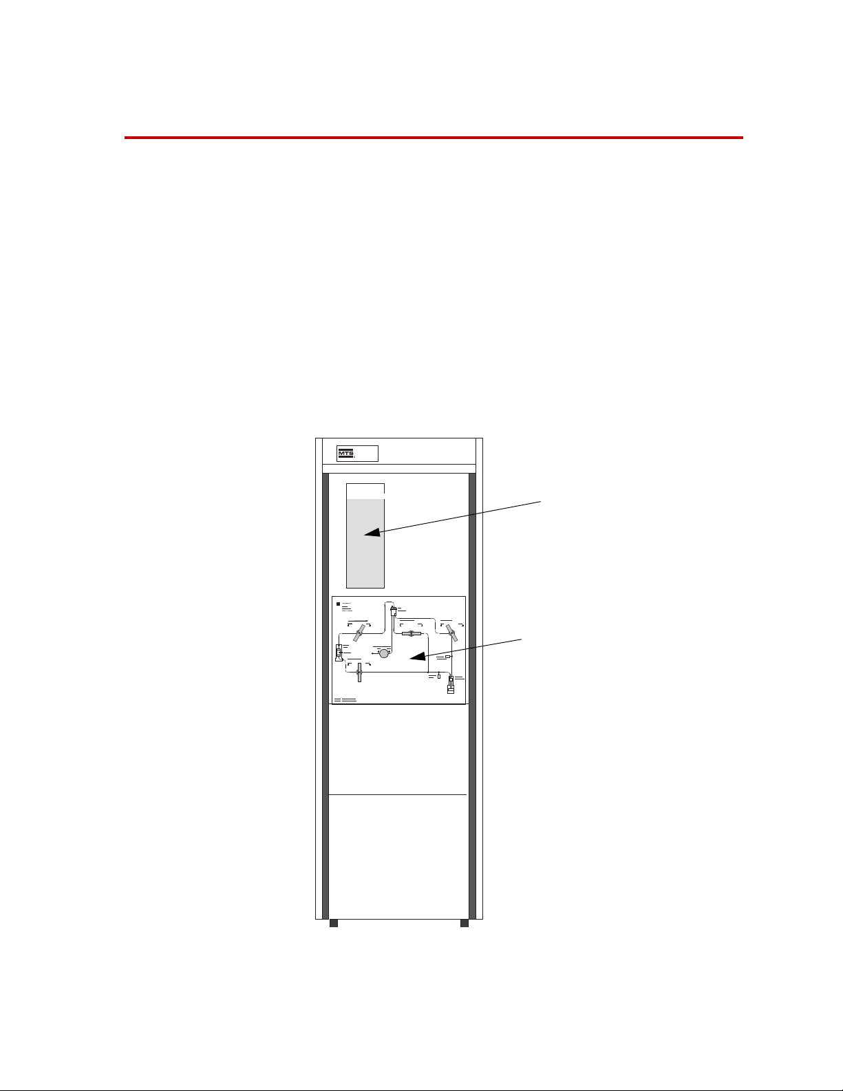
815
Fluid
Reservoir
Control
Panel
This section describes the Model 286.30 Pore Pressure Intensifier, its role in the
typical rock mechanics test system, and other system components typically used
with the Pore Pressure Intensifier. Specifications and dimensions are also
included.
The Model 286.30 Pore Pressure Intensifier is designed to provide a source of
fluid at pressures suitable for use in applying pore pressure to a rock specimen in
a triaxial cell. The PPI is used to fill the specimen’s pores with pore fluid,
pressurize the fluid, and control the pressure.
Some model versions produce pore pressures up to 20,000 psi (140 MPa). The
maximum fluid volume that can flow during one stroke of the PPI’s internal
3
pressure intensifier can be as high as 80 cubic inches (1300 cm
“Specifications and Dimensions” on page 17 for specifications for all models.
). See
286.30 Pressure Intensifier Introduction
13
Page 14
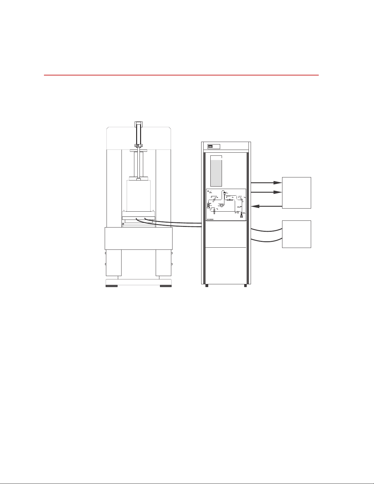
Overview of Typical Pore Pressure Intensifier System
Pore Pressure
Instensifier
(PPI)
815
Triaxial
Cell
High
Pressure
Hoses
Typical Load Frame
(rear view)
Pressure
Return
*Feedback Signals
Electronic
Controller
Equipment
Hydraulic
Power
Supply
Displacement*
Pressure*
286.30_001
Overview of Typical Pore Pressure
Intensifier System
The major system components typically used with the Pore Pressure Intensifier
are shown below.
14
Introduction
As shown in the figure, a separate hydraulic power supply acts as the primary
power source for the Pore Pressure Intensifier. Hydraulic fluid pressures up to
21 MPa (3,000 psi) are translated into pore fluid pressures up to 140 MPa
(20,000 psi) under servo control provided by separate electronic controller
equipment.
Pressure and displacement transducers in the PPI provide signals proportional to
their respective variables, enabling the external electronic controller equipment
to measure these variables and to control either the pressure produced by the PPI,
or the linear displacement of the pressure intensifier’s piston relative to a fixed
reference.
While the displacement transducer output signal is proportional to the
displacement of the pressure intensifier’s piston, relative to a reference point, the
electronic control equipment associated with this transducer is usually calibrated
in units of displacement.
286.30 Pressure Intensifier
Page 15

Description of Major Components
1
2
4
3
5
6A
8
7
9
6B
Description of Major Components
The following figure and table identify and describe the major components of the
Model 286.30.
Pore Intensifier Major Components
286.30 Pressure Intensifier Introduction
15
Page 16

Description of Major Components
Major Components
Item Component Description
1 Cabinet
2 Reservoir
3 Operator control
panel
4 Pressure
transducer
5 Pressure relief
valve
6 Pressure
intensifier
7 Hydraulic service
manifold
8 Servovalve
Enclosure mounted on casters. Includes leveling legs for stability and a
hinged rear access door.
Clear acrylic container . Includes filler port with strainer which also acts as a
vent for escaping gases.
The panel contains all the valves used during operation and includes a
schematic of the unit as an aid during operation.
Provides a signal which represents the level of pore fluid pressure being
applied to the specimen. The signal is used by the electronic controller
equipment as feedback when pressure is the controlled variable.
Relieves pressure if pressure in the system exceeds the PPI’s pressure rating
by a certain amount.
Actuator which uses servovalve controlled hydraulic fluid to pressurize the
pore fluid. The top end, identified as “6A,” is the high pressure, pore fluid
part of the actuator. The lower part, “6B” is the low pressure, hydraulic fluid
end.
Provides a hydraulic interface between the external hydraulic power supply
and the pressure intensifier. Provides mounting for various components
such as the servovalve and accumulators.
Controls flow and pressure of hydraulic fluid applied to the input side of the
pressure intensifier.
9 Linear transducer
Provides a signal that is proportional to the linear displacement of the
pressure intensifier’s piston relative to a fixed reference.
16
Introduction
286.30 Pressure Intensifier
Page 17

Specifications and Dimensions
The following tables list the dimensions/weights and specifications for the Model
286.30 Pore Pressure Intensifier.
Note Specifications and dimensions are subject to change without notice.
Contact MTS for verification of specifications and dimensions critical to
your requirements.
Dimensions and Weights
Parameter All Models
Height 7 4 in. (1880 mm)
Width 23.6 in. (600 mm)
Depth 31.6 in. (803 mm)
Weight 1000 lb (454 kg)
Reservoir Capacity 1.6 gallon (7.3 liters)
Specifications and Dimensions
Parameter Model 286.30-01 Model 286.30-02 Model 286.30-03
Maximum Output
Pressure, MPa/PSI
Output Volume
cu. cm/in.
Recommended
Fluids
Maximum Fluid
Temperature
80/12,000
325/20
The individual Pore Pressure Intensifier is built to be compatible with one or more
fluids. Fluids such as pure water and non-corrosive water solutions, corrosive saline
and acid solutions and refined mineral oils, such as PG
The 286.30-02 is the same as the 286.30-01 except it accepts a brine solution.
Use of fluids not compatible with the PPI can damage internal components.
Refer questions regarding appropriate fluid for a specific PPI to your local MTS
Service Engineer or to MTS Systems Corporation.
75°C/165°F for all models
Note Many triaxial cells are capable of heating pore fluid to temperatures that
exceed this value. Therefore, it is imperative that fluid from the triaxial cell
not be allowed to circulate back into the PPI while fluid temperature is above
75°C/165°F.
80/12,000
325/20
140/20,000
325/20
®
and Multitherm®, are used.
286.30 Pressure Intensifier Introduction
17
Page 18

Specifications and Dimensions
18
Introduction
286.30 Pressure Intensifier
Page 19

Operation
This section contains procedures for all operations involving the flow and
pressurization of pore fluid. All operating controls on the Pore Pressure
Intensifier (PPI) are described. Safety considerations that should be observed
while operating the Pore Pressure Intensifier are included.
In addition to the Pore Pressure Intensifier, a pore pressure system typically
includes a hydraulic power supply, some type of electronic controller equipment,
and a triaxial cell designed to apply pore pressure to a rock specimen. Before
attempting to operate the PPI, become familiar with each component of the pore
pressure system by reading the introduction sections of the manuals that apply.
The table also indicates that pressurization and depressurization of pore fluid is
primarily under the control of the electronic controller equipment. Because of the
variety of electronic controller equipment that can be used with a pore pressure
system, information provided in this manual is limited to that which will enable
you to relate PPI parameters, such as fluid pressure and fluid volumetric
displacement, to controller functions such as the command, feedback, control,
error and limit functions.
A typical procedure for operating the Confining Pressure Intensifier would be:
1. Filling the reservoir; see “Filling the Reservoir” on page 30.
2. Filling the pressure intensifier; see “Filling the Pressure Intensifier” on page
32.
3. FIlling the specimen’s pores with pore fluid; see “Filling the Specimen’s
Pores with Pore Fluid” on page 35.
4. Heating the triaxial cell; see “Heating the Triaxial Cell” on page 39.
5. Pressurizing and depressurizing the pore fluid; see “Pressurizing and
Depressurizing the Pore Fluid” on page 40
6. Draining the reservoir to an external location; see “Draining the Reservoir to
an External Location” on page 42
Before operating the system for the first time, simulate the desired operation.
Locate the controls involved with each step, without actually performing the
adjustment. In this way, you will become familiar with the information that is
required or the decisions that must be made before beginning actual operation.
286.30 Pressure Intensifier Operation
19
Page 20

Functions of the Front Panel Controls
1
2
4
3
5
Functions of the Front Panel Controls
The following figure shows the PPI’s operational controls, superimpos ed on the
front panel hydraulic schematic. The following table describes items 1 through 5,
shown in the figure.
The table lists the operational effects of each individual control. However, note
that performing the various operations listed in the table usually involves the
manipulation of two or more of the controls.
20
Operation
286.30 Pressure Intensifier
Page 21

TEM CONTROL FUNCTION
I
Functions of the Front Panel Controls
1 Pore Fluid
Output
2 Pore Fluid
Input
3 Reservoir
Drain/Fill
4 Reservoir
Return
5 Intensifier Fill
Adjustable hand-valve. Turning the valve counterclockwise toward Open allows
air to be vented from the triaxial cell to the reservoir while filling the rock
specimen’s pores with fluid.
The valve is closed while pressurizing the pore fluid.
Adjustable hand-valve. Turning the valve counterclockwise toward Open allows
fluid to flow into the rock specimen, or it allows pore fluid in the specimen to be
pressurized by the pressure intensifier. Turning the valve fully clockwise to Close
closes the input to the triaxial cell.
The valve must be closed to prevent fluid from draining from the reservoir.
The arrow to the left of the valve, shown on the front panel schematic above,
represents a hose that could be attached to the valve, from the rear of the panel.
The reservoir could be filled via the attached hose by means of a suitable external
pump while the valve is open. (The reservoir is usually filled by pouring fluid
through the vent on top of the reservoir.)
Opening the valve also allows the reservoir to be drained, via the hose, to an
external container or drain.
Adjustable hand-valve. The valve is opened during the intensifier fill procedure to
allow air to be purged from the intensifier. The valve is closed while pressurizing
the pore fluid.
Adjustable hand-valve. Turning the valve counterclockwise toward Open allows
pore fluid to flow from the reservoir to the pressure intensifier. The valve must be
closed before pressurizing the triaxial cell.
286.30 Pressure Intensifier Operation
21
Page 22

High Pressure Precaution
WARNING
CAUTION
High Pressure Precaution
Pore fluid can attain very high pressures. High pressure fluid can cause
severe injury or death.
Ensure pressure gage reads zero before opening the Pore Fluid Output valve.
Follow all procedures provided by this manual.
The Model 286.30 Pore Pressure Intensifier is capable of producing very high
pressures. If mishandled or improperly adjusted, it is capable of seriously
injuring and/or killing personnel, damaging itself, and damaging surrounding
equipment. If care is taken however, the unit can provide prolonged service
without incidents.
High Temperature Precaution
Temperature of fluid in the triaxial cell can exceed the temperature rating of
the Pore Pressure Intensifier. This could damage the Pore Pressure
Intensifier.
Temperature will increase when applying pressure. So if heated to maximum
temperature before pressure is applied, increasing pressure too fast can cause
the temperature to increase to a point where it can damage the equipment;
primarily the transducers.
Also allow fluid in the triaxial cell to cool to 75 °C (167 °F) or less before emptying
the triaxial cell back to the reservoir of the Pore Pressure Intensifier.
The Model 286.30 Pore Pressure Intensifier has a temperature rating of 75 °C
°F). Many triaxial cells have higher temperature ratings. Therefore, the
(167
Pore fluid in the triaxial cell must be allowed to cool to 75
before being recirculated into the Pore Pressure Intensifier. If fluid having a
temperature higher than 75
acrylic reservoir and associated flexible tubing can be damaged.
°C (167 °F) is allowed to circulate into the PPI, the
°C (167 °F), or below ,
22
Operation
286.30 Pressure Intensifier
Page 23

Pore Pressure System Operation Considerations
Pore Pressure System Operation Considerations
Operating in Conjunction with a Confining Pressure System
Rock mechanics studies typically involve the use of a triaxial cell, a pore
pressure system and a confining pressure system. In such use, pore pressure is
applied to the flat, end surfaces of a cylindrical rock specimen while confining
pressure is applied to the curved, outer walls of the cylinder.
An impermeable jacket is usually placed around the curved outer cylinder wall to
act as a barrier between the open pores on this surface and the confining fluid,
thus preventing confining fluid flow into the specimen. In order to avoid
rupturing the impermeable jacket, pore fluid pressure should never be higher than
confining fluid pressure.
286.30 Pressure Intensifier Operation
23
Page 24

Pore Pressure System Operation Considerations
Closed-loop Control Modes Used for Pressurizing Pore Fluid
The pressure intensifier inside the PPI operates under closed-loop control
principles.
External electronic controller equipment receives signals from a pressure
transducer in the PPI, and also from a linear displacement transducer, which
indicates current pressure intensifier piston position relative to a reference
position. The magnitudes of the two (dc) signals are proportional to their
respective variables. Either one of these signals can be selected, as a feedback
signal for control purposes, at the controller; both are simultaneously available
for readout purposes.
Pressure control mode Calibration of the electronic controller equipment is such that the signal from the
pressure transducer relates directly to pressure inside the triaxial cell, in MPa or
psi, depending on how the controller equipment was calibrated. When the output
of the pressure transducer is chosen as a feedback signal for the controller,
pressure becomes the controlled, or independent variable, and displacement
becomes a dependent, or uncontrolled variable. This is referred to as the pressure
control mode.
Displacement control
mode
The pressure control mode is the preferred control mode for pressurizing pore
fluid.
The signal from the PPI’s linear displacement transducer, however, is usually
calibrated to relate to the volume
pressure intensifier’s piston being displaced some linear distance from a
reference point. When the output of the displacement transducer is chosen as a
feedback signal for the controller, volumetric displacement becomes the
controlled, or independent variable and pressure becomes a dependent, or
uncontrolled variable. This is usually referred to as the displacement control
mode and calibration is usually in either cubic inches or cubic centimeters.
The displacement control mode is less desirable for use than the pressure control
mode because very small changes in displacement cause very large changes in
pressure. Also, if the displacement control mode were used while the triaxial cell
was being heated, the controller would be insensitive to fluid expansion due to
increasing temperature and very high pressures would rapidly develop.
If the triaxial cell is equipped with heaters, it is important to remain aware of the
effects of thermal expansion of the fluid when the Pore Pressure Intensifier is in
operation. This is described in “Effects of Thermal Expansion of Pore Fluid” on
page 26.
The displacement control mode is most useful while performing PPI operations
such as filling the pressure intensifier or positioning the piston of the pressure
intensifier before starting a pressurization sequence in the pressure control mode.
of fluid that is displaced as a result of the
24
Operation
286.30 Pressure Intensifier
Page 25

Pore Pressure System Operation Considerations
Typical Calibration of Control Parameters
The two control parameters, pressure and volumetric displacement (unlike the
force parameter in axial testing, which usually has both tensile and compressive
force directions or polarities) are uni-directional. Positive commands applied to
the electronic controller equipment will cause pressure or volumetric
displacement (depending on which parameter is being controlled) to increase to
some positive level above zero.
For example, to cause pressure to increase from zero to full scale, you would
adjust the command input to the controller to +100%.
Applying a negative command at the controller, in either control mode (see
“Closed-loop Control Modes Used for Pressurizing Pore Fluid” on page 24 for
definition of “control mode”) would cause the piston rod of the pressure
intensifier to fully retract. While testing, negative commands have no practical
use and can cause the error detectors (see “Use of Error Detectors and Limit
Detectors While Pressurizing” on page 27) to trip because neither controllable
variable can go negative. However, during certain pretest operations, such as
when causing the pressure intensifier to stroke to its low end or starting position,
negative commands are used.
286.30 Pressure Intensifier Operation
25
Page 26

Pore Pressure System Operation Considerations
Effects of Thermal Expansion of Pore Fluid
When heaters are used to heat the triaxial cell and the specimen and pore fluid,
the pore fluid expands.
Thermal expansion
when operating in
pressure control mode
Thermal expansion
when operating in
displacement control
mode
If the pore pressure system is being operated in the pressure control mode while
the triaxial cell is being heated, pressure inside the triaxial cell normally will not
increase as temperature rises. This is because any tendency for pressure to
increase, as a result of thermal expansion or any other cause, will be
automatically corrected by the controller. The piston of the PPI’s pressure
intensifier will simply retract slightly, as required to maintain the correct
pressure, in spite of increasing thermal expansion, assuming that the pressure
intensifier’s piston does not reach the physical end of its stroke in the process. If
the piston cannot retract sufficiently to maintain the programmed pressure, pore
pressure will increase rapidly with further thermal expansion.
If the pore pressure system is being operated in the displacement control mode,
while the triaxial cell is being heated, pore pressure will increase rapidly
thermal expansion occurs, because, except for various monitoring devices such
as limit detectors, the controller is insensitive to pressure changes while in
displacement control.
Properly executed operating procedures can avoid either of the situations that are
described under this heading, where pressure increases undesirably because of
thermal expansion. They are described here to indicate that such situations can
develop and to provide a basis for describing the use of the controller’s error
detectors and limit detectors.
as
26
Operation
286.30 Pressure Intensifier
Page 27

Pore Pressure System Operation Considerations
Use of Error Detectors and Limit Detectors While Pressurizing
Information under “Effects of Thermal Expansion of Pore Fluid” on page 26
describes two situations in which pore pressure can be, or can become, an
uncontrolled variable. These situations, and actually all “normal” pressurizing
procedures, warrant the use of whatever devices are available, on the electronic
controller equipment, that enable system conditions to be monitored and system
operation to be shut down in the event abnormal or undesirable operating
conditions occur.
In the first situation, the controller is controlling pressure but becomes unable to
compensate for additional pressure increase caused by further thermal expansion
if the piston of the pressure intensifier bottoms out and cannot retract any further.
In this case, two monitoring circuits, common to most controllers, would afford
some protection, if properly pre-adjusted.
Error detectors Error detectors monitor the amplitude of the controller’s error signal (which is
proportional to the difference between command and feedback) and are therefore
always associated with the controlled variable. In the situation where the
controller becomes unable to compensate for further thermal expansion (because
the pressure intensifier is unable to retract any further), the error signal will begin
to increase in magnitude as soon as the controller can no longer compensate, if
further thermal expansion occurs. If the error detectors had been adjusted to be
sensitive to small error levels, the pressurization process would be terminated
very soon after the problem occurred.
Limit detectors Limit detectors can be set up to monitor the level of variables, whether the
variables are independent (controlled) or dependent (uncontrolled). In the first
situation, Thermal expansion when operating in pressure control mode, the
controller’s limit detector could also have been set up to terminate the
pressurization procedure in the event that pressure exceeded some preestablished limit. With both error detectors and limit detectors in use monitoring
the controlled variable, the pressur izat ion procedure would be terminated by
whichever detector reacted first.
In the second situation, Thermal expansion when operating in displacement
control mode, with volumetric displacement the controlled variable, the error
detector could be adjusted to react to some unusual level of error (associated with
the controlled variable, volumetric displacement) and the limit detecto r coul d be
set up to actuate if the dependent variable, pressure, exceeded some undesired or
unanticipated level.
Because an unanticipated high pressure level is nearly always of greater concern
than is high volumetric displacement, pressure should always be monitored by
either limit detectors or error detectors. Limit detectors provide some ad vantage
over error detectors in that precise limit levels are easily established. Error
detectors actuate when feedback (the actual level of the controlled variable)
deviates from command (the desired level of the controlled variable) by some
presettable amount and can detect such errors regardless of the level of the
controlled variable. Both detector types offer unique advantages and should be
used simultaneously and judiciously according to the test situation at hand.
286.30 Pressure Intensifier Operation
27
Page 28

Pore Pressure System Operation Considerations
Effects of Air in the System, Need to Expel
The operating procedures provided in this section include instructions for
removing air or gases from the pressurized parts of the system whenever that is a
concern.
Large volumes of air can affect system response time, when operating in the
pressure control mode, or affect the expected relationship between pressure and
volumetric displacement, when operating in the displacement control mode,
especially when low pressures are involved.
28
Operation
286.30 Pressure Intensifier
Page 29

Operating Procedures
WARNING
The operating procedures are presented here in the usual order of occurrence.
The first procedure, “Filling the Reservoir” on page 30, assumes the reservoir is
to be filled for the first time, or that fluid quantity in the reservoir needs to be
replenished. Subsequent procedures assume that the condition of the system is as
established by the successful performance of the immediately preceding
procedure.
Hydraulic power will be applied during some operating procedures.
Conditions hazardous to life and equipment exist on all syste ms or
equipment that may be connected to the same hydraulic power source.
Before turning on hydraulic power, first make sure that all systems or equipment
that use the same hydraulic power source are in appropriate condition for
application of hydraulic power.
Operating Procedures
Make certain no one is performing work on other systems or equipment sharing
the same hydraulic power source.
Inform other people in the vicinity that you are about to turn on hydraulic power.
286.30 Pressure Intensifier Operation
29
Page 30

Operating Procedures
Filling the Reservoir
One method of filling the reservoir is simply to remove the cap on the reservoir’s
vent (top of reservoir) and to pour fluid in from the top.
If the fluid source is pressurized, as with tap water or a pressurized container or
one equipped with a pump, connection can be made directly to the capped port on
the Reservoir Drain/Fill valve.
External plumbing can be attached to the Reservoir Drain/Fill valve to allow
either draining or filling of the reservoir, or both, as desired.
Note Fluid to be added must be a recommended type (see Specifications) and
Fill Procedures Use one of the following procedures to fill the reservoir:
must be suitable for the individual PPI and the same as any fluid
currently in the Pore Pressure Intensifier. (Don’t mix fluid types.)
Filling the reservoir
through the vent
Filling the reservoir from
a pressurized source
connected to the
Reservoir Drain/Fill
valve
1. Close the Reservoir Drain/Fill valve.
2. Remove the cap on the reservoir’s vent (top of reservoir)
3. Pour fluid in from the top until the reservoir is abou t three-fourths full.
4. Replace the cap on the reservoir’s vent (top of reservoir).
1. Open the Reservoir Drain/Fill valve a small amount to allow fluid to flow
up through the valve until the reservoir is about three-fourths full,
2. Close the Reservoir Drain/Fill valve.
30
Operation
286.30 Pressure Intensifier
Page 31

Operating Procedures
Close while filling
through reservoir
vent. Open while
filling through
reservoir drain/fill
valve.
Filling the Reservoir
286.30 Pressure Intensifier Operation
31
Page 32

Operating Procedures
WARNING
Filling the Pressure Intensifier
It is necessary to perform this procedure only when the pore pressure end of the
pressure intensifier contains air rather than pore fluid, for example, when using
the PPI for the first time, or after overhaul or maintenance has been performed on
the pressure intensifier. The figure shown at the end of this procedure shows the
sequence of actions described in the procedure.
During the course of normal day-to-day operating procedures the pore fluid end
of the pressure intensifier will always be filled with pore fluid, to the extent
allowed by the current displacement (position) of its piston, assuming faulty
operating procedures have not sucked air into the pressure intensifier.
Note During this procedure the PPI will be operated under closed-loop control.
Because of the large variety of electronic controller equipment in use,
explicit instructions cannot be provided for some steps. Refer to the
system operation manual.
Purpose of this
procedure:
Preliminary steps or
conditions:
This procedure establishes three simultaneous conditions in preparation for
pressurizing the pore fluid: it fills the high pressure end of the pressure intensifier
with pore fluid, it expels all air from the high pressure end of the pressure
intensifier, and positions the pressure intensifier’s piston near the start of its
stroke range.
• The reservoir is three-fourths full of pore fluid.
• The Reservoir Drain/Fill valve is fully closed.
• The Pore Fluid Input valve is closed.
• Hydraulic power (from the external hydraulic power supply) is not applied
to the PPI at this time.
Hydraulic power will be applied during this procedure. Conditions that can
be hazardous to life and equipment can exist on all systems or equipment
that are connected to the same hydraulic power source.
Before turning on hydraulic power, make sure that all systems or equipment that
use the same hydraulic power source are in an appropriate condition before you
turn on hydraulic power.
32
Operation
Make certain no one is performing work on other systems or equipment that share
the same hydraulic power source as the PPI. If people are working on other
systems or equipment, inform them that you intend to turn on hydraulic power.
Inform other people in the vicinity that you are about to turn on hydraulic power.
286.30 Pressure Intensifier
Page 33

Operating Procedures
Procedure: 1. Open the Intensifier Fill valve several turns counterclockwise.
2. Check that the Reservoir Return valve is fully closed.
3. Set up the PPI’s electronic controller for operation in the displacement
control mode.
4. At the PPI’s controller equipment, turn on low hydraulic pressure.
5. At the displacement controller, cause the pressure intensifier’s piston rod to
slowly stroke to the lower end of it’s travel (piston fully retracted, zero
displacement position, zero command). This is done by means of the Set
Point control on the controller.
As the pressure intensifier’s piston retracts, fluid from the reservoir is drawn
into the pressure intensifier.
6. Close the Intensifier Fill valve.
7. Open the Reservoir Return valve two turns.
8. At the displacement controller, cause the pressure intensifier’s piston rod to
stroke slowly
reservoir for air bubbles. This action forces any air out of the intensifier.
When air bubbles cease to appear, stop the motion of the pressure
intensifier’s piston rod.
upward (extension, positive command) while observing the
Note If air bubbles are still evident when the pressure intensifier’s piston
reaches the top of its stroke (full extension), repeat steps 1, 2 and 5
through 8.
9. Fully close the Reservoir Return valve and open the Intensifier Fill valve
two turns.
10. At the displacement controller, cause the pressure intensifier’s piston rod to
slowly stroke downward again until it is at about 10% of its full-scale stroke
range (10% extended). This action positions the piston in preparation for
pore fluid to flow to and pressurize the sample.
11. At the external controller equipment, turn off hydraulic power to the Pore
Pressure Intensifier.
286.30 Pressure Intensifier Operation
33
Page 34

Operating Procedures
Filling the Pressure Intensifier
2 - Close
7 - Open, two turns
9 - Close
1 - Open
6 - Close
9 - Open
(Procedural steps not shown are performed
on the controller equipment.)
(closed)
(closed)
34
Operation
286.30 Pressure Intensifier
Page 35

Filling the Specimen’s Pores with Pore Fluid
CAUTION
This procedure will cause pore fluid to flow into (and purge air from) the lines
between the PPI’s pressure intensifier and the triaxial cell, the triaxial cell, the
specimen’s pores, and the lines between the triaxial cell and the PPI’ s Por e Fluid
Output valve. (Pore fluid will be allowed to flow through the PPI’s Pore Fluid
Output valve until a very small flow of pore fluid is seen entering the PPI’s
reservoir.)
Note During this procedure, the PPI will be operated under closed-loop control
in the pressure control mode. Because of the variety of electronic
controller equipment in use, explicit instructions cannot be provided for
some steps. Refer to the system operation manual.
Operating Procedures
Preliminary steps or
conditions:
• The pressure intensifier is full of pore fluid and the piston is (approximately)
at the 10% displacement position, as established in the preceding procedure.
• The Intensifier Fill, Reservoir Return and Reservoir Drain/Fill valves
are all closed.
• A jacketed specimen is installed in the triaxial cell and the cell is sealed for
operation.
• Hydraulic power (from the external hydraulic power supply) is not applied
to the PPI at this time.
Pore fluid pressure should not be higher than confining fluid pressure.
If pore fluid pressure is higher than confining fluid pressure, the jacket on
the specimen will rupture.
Always maintain confining fluid pressure at a higher level than pore fluid pressure.
(Refer to the manual for the Confining Pressure Intensifier for instructions on
controlling confining pressure.)
286.30 Pressure Intensifier Operation
35
Page 36

Operating Procedures
WARNING
Procedure: 1. At the PPI’s control panel, open the Pore Fluid Input and Pore Fluid
Output valves.
2. Set up the PPI’s electronic controller for operation in the pressure control
mode.
Hydraulic power will be applied during this procedure. Conditions that can
be hazardous to life and equipment can exist on all systems or equipment
that are connected to the same hydraulic power source.
Before turning on hydraulic power, make sure that all systems or equipment that
use the same hydraulic power source are in an appropriate condition before you
turn on hydraulic power.
Make certain no one is performing work on other systems or equipment that share
the same hydraulic power source as the PPI. If people are working on other
systems or equipment, inform them that you intend to turn on hydraulic power.
Inform other people in the vicinity that you are about to turn on hydraulic power.
3. At the PPI’s controller equipment, turn on high hydraulic pressure.
Note In the following steps fluid will flow into the specimen, forcing air out to
the reservoir.
On later PPI versions, the line from the Pore Fluid Output control expels
air/fluid into the reservoir from above the fluid level -- watch for bubblefree fluid to flow into the reservoir. On earlier PPI versions the line from
the Pore Fluid Output control enters into the bottom of the reservoir -watch for the bubble stream to stop flowing.
4. At the pressure controller, apply a positive command that is sufficient to
cause pore fluid to flow. This is done by turning the Set Point control on the
controller.
(Before fluid can be seen flowing into the reservoir, you can determine that
it is flowing into the triaxial cell by watching the displacement variable, as
displayed on the controller equipment. The rate of flow is proportional to
the rate of change of the displacement variable.)
5. Watch for air bubbles entering the reservoir (see the note above.) After
bubbles are no longer observed, close the Pore Fluid Output valve.
After the Pore Fluid Output valve is closed, the pore pressure system will
remain under closed-loop control at a pressure level corresponding to the
level of the applied pressure command.
36
Operation
286.30 Pressure Intensifier
Page 37

Operating Procedures
Note Perform step 6 only if the pressure intensifier reaches the end of its travel
while bubbles are still being observed entering the reservoir.
6. If the pressure intensifier’s piston travels to the end of its stroke before a
bubble-free flow of fluid is observed entering the reservoir, it will be
necessary to stroke the actuator again to achieve the desired results. Do the
following:
A. Reduce the command applied to the pressure controller until the
pressure variable indicates approximately zero pressure.
B. Open the Intensifier Fill valve.
C. Close the Pore Fluid Input valve.
D. Reduce the command applied to the pressure controller further (it may
have to go slightly negative) until the pressure intensifier’s piston
returns to (approximately) the 10% displacement position (watch the
displacement variable).
E. Close the Intensifier Fill valve.
F. Repeat steps 4 and 5.
286.30 Pressure Intensifier Operation
37
Page 38

Operating Procedures
Filling the Specimen’s Pores with Pore Fluid
5 - Close
1 - Open
(Procedural steps not shown are performed
on the controller equipment.)
(closed)
(closed)
(closed)
38
Operation
286.30 Pressure Intensifier
Page 39

Heating the Triaxial Cell
WARNING
Some users choose to heat the triaxial cell before applying test pressures to the
cell. Others apply test pressures while the cell is heating. In either case, the PPI
must be operated in pressure control mode during the heating process. Also, the
Pore Fluid Output valve on the PPI’s front panel should be closed to prevent hot
fluid from entering and damaging the reserv oir.
Pressure inside the triaxial cell could reach high levels while the cell is
being heated.
This could cause personal injury or death or damage to the equipment or
specimen.
Always operate the PPI in pressure control mode during the heating process, as
described in “Pressurizing and Depressurizing the Pore Fluid” on page 40.
Operating Procedures
The process of heating the triaxial cell is described as a step in “Pressurizing and
Depressurizing the Pore Fluid” on page 40.
Important Be familiar with the warning and cautions pertaining to heating fluid
within the triaxial cell. See “High Temperature Precaution” on p a ge
22 and “Effects of Thermal Expansion of Pore Fluid” on page 26.
286.30 Pressure Intensifier Operation
39
Page 40

Operating Procedures
CAUTION
Pressurizing and Depressurizing the Pore Fluid
Purpose of this
procedure:
Preliminary steps or
conditions:
This procedure describes how and when:
A. to pressurize the pore fluid.
B. to heat and cool th e triax ial cell, if req uired.
C. to depressurize the pore fluid at the end of the test.
The pore pressure intensifier system should be in the same condition as existed
after performing “Filling the Specimen’s Pores with Pore Fluid” on page 35.”
• A jacketed specimen is installed in the triaxial cell and the cell is sealed and
ready for operation.
• High hydraulic pressure is turned on and the PPI is being controlled by the
external controller equipment operating in pressure control mode.
• The Intensifier Fill, Reservoir Return, Reservoir Drain/Fill and the Pore
Pressure Output valves are all closed.
• The Pore Pressure Input valve is open.
Note If any of these conditions are not met, perform “Filling the Reservoir” on
page 30 as necessary.
Pore fluid pressure should not be higher than confining fluid pressure.
If pore fluid pressure is higher than confining fluid pressure, the jacket on
the specimen will rupture.
Always maintain confining fluid pressure at a higher level than pore fluid pressure.
(Refer to the manual for the Confining Pressure Intensifier for instructions on
controlling confining pressure.)
40
Operation
286.30 Pressure Intensifier
Page 41

Procedure:
Operating Procedures
First, check that the
pressure intensifier
piston is suitably
positioned for
pressurization
operations
Re-position the piston, if
necessary
1. Observe the displacement signal to determine that the pressure intensifier’s
piston is in a suitable position for performing pressurizing operations.
Usually , the pressure intensifier’s piston is placed somewhere between 10%
and 20% displacement before starting pressurizing operations.
The best position is that which will allow sufficient retraction of the piston,
if needed to compensate for any thermal expansion of pore fluid, caused by
heating the triaxial cell, while also providing the piston extension required
to pressurize the pore fluid.
2. Perform this step only if it is necessary to reposition the pressure
intensifier’s piston, as determined by step 1. Otherwise, skip to step 3.
A. Reduce the command applied to the pressure controller until the
pressure variable indicates approximately zero pressure.
B. Close the Pore Fluid Input valve.
C. Open the Intensifier Fill valve.
D. Change the command applied to the pressure controller as required to
cause the pressure intensifier’s piston to move slowly
direction (watch the displacement variable), and while the piston is in
the desired position, close the Intensifier Fill valve.
E. Open the Pore Fluid Input valve.
in the desired
Note Steps 3 and 4 relate to heating the triaxial cell (if applicable) and
pressurizing the pore fluid. Perform steps 3 and 4 in whatever sequence
is desired.
Important Be familiar with the warning and cautions pertaining to heating fluid
within the triaxial cell. See “High Temperature Precaution” on p a ge
22 and “Effects of Thermal Expansion of Pore Fluid” on page 26.
Heat the triaxial cell, if
applicable
3. If the triaxial cell is to be heated, set up the temperature controller
equipment as required to bring the triaxial cell to operating temperature.
Pressurize the pore fluid 4. On the PPI’s pressure controller, perform the operations necessary to bring
triaxial cell pore pressure to test level.
Cool and depressurize
the triaxial cell
5. After the test is over , perfor m the op erations necessary at the PPI’s pressure
controller to reduce triaxial cell pore pressure to a zero level.
6. If the triaxial cell has been heated, adjust the temperature controller
equipment to allow the triaxial cell to cool.
7. Turn off hydraulic power.
8. Close the Pore Fluid Input valve.
9. Slowly open the Pore Fluid Output valve to release any remaining pore
fluid pressure to the reservoir.
286.30 Pressure Intensifier Operation
41
Page 42

Operating Procedures
Pressurizing and Depressurizing the Pore Fluid
9 - Open
2B - Close
2E - Open
8 - Close
(Procedural steps not shown are performed
on the controller equipment.)
(closed)
2C - Open
2D - Close
(closed)
(initially
closed)
Draining the Reservoir to an External Location
To drain the reservoir: 1. Insert the end of the hose from the Drain/Fill valve into an external
container.
2. Open the Drain/Fill valve.
42
Operation
286.30 Pressure Intensifier
Page 43

Page 44

m
MTS Systems Corporation
14000 Technology Drive
Eden Prairie, Minnesota 55344-2290 USA
Toll Free Phone: 800-328-2255
(within the U.S. or Canada)
Phone: 952-937-4000
(outside the U.S. or Canada)
Fax: 952-937-4515
E-mail: info@mts.com
http://www.mts.com
ISO 9001:2000 Certified QMS
 Loading...