

Page 1

be certain.
m
Series 252 Servovalves
Product Information
011-182-906 N
Page 2

Copyright information © 1981-2013 MTS Systems Corporation. All rights reserved.
Trademark information MTS is a registered trademark of MTS Systems Corporation within the United
States. This trademark may be protected in other countries.
DTE is a registered trademark of Exxon Mobil Corporation. Tellus is a registered
trademark of Shell Oil Corporation. All other trademarks or service marks are
property of their respective owners.
Publication information
Manual Part Number Publication Date
111829-01A March 1981
111829-02A June 1981
111829-03A July 1981
111829-04A June 1982
111829-05A February 1982
111829-06A February 1983
111829-06B January 1988
111829-06F January 1993
111829-06G November 1998
011-182-903 H November 1999
011-182-903 J September 2003
011-182-903 K April 2007
011-182-903 L March 2008
011-182-903 M October 2009
011-182-903 N March 2013
2
Series 252 Servovalve Product Information
Page 3

Contents
Technical Support 5
How to Get Technical Support 5
Before You Contact MTS 5
If You Contact MTS by Phone 6
Problem Submittal Form in MTS Manuals 7
Preface 9
Before You Begin 9
Conventions 10
Documentation Conventions 10
Introduction 13
About the Servovalve 14
Servovalve Function 14
Servovalve Applications 16
Single Servovalves 17
Dual Servovalves 18
Three-Stage Servovalves 19
252 Servovalve General Specifications 20
252 Servovalve Flow Ratings 21
252 Servovalve Performance Characteristics 22
252 Servovalve Dimensions 23
Installation 25
252 Servovalve Installation 25
252 Servovalve Cable Connections 28
Five-Port Operation—252.2x Servovalve 29
Five-Port Operation—252.3x Servovalve 30
Series 252 Servovalve Product Information Contents
3
Page 4

Maintenance 33
Replace the Servovalve Filter Element 33
Adjust the Mechanical Null 35
Troubleshooting Guide 39
4
Contents
Series 252 Servovalve Product Information
Page 5

Technical Support
How to Get Technical Support
How to Get Technical Support
Start with your
manuals
Technical support
methods
The manuals supplied by MTS provide most of the information you need to use
and maintain your equipment. If your equipment includes software, look for
online help and README files that contain additional product information.
If you cannot find answers to your technical questions from these sources, you
can use the Internet, e-mail, telephone, or fax to contact MTS for assistance.
MTS provides a full range of support services after your system is installed. If
you have any questions about a system or product, contact Technical Support in
one of the following ways.
www.mts.com The web site provides access to our technical support staff by means of an
onlineform:
www.mts.com > Contact MTS > Service & Technical Support button
E-mail tech.support@mts.com
Telephone MTS Call Center 800-328-2255
Weekdays 7:00 A.M. to 5:00 P.M., Central Time
Fax 952-937-4515
Please include “Technical Support” in the subject line.
Outside the U.S. For technical support outside the United States, contact your local sales and
service office. For a list of worldwide sales and service locations and contact
information, use the Global MTS link at the MTS web site:
www.mts.com > Global MTS > (choose your region in the right-hand
column) > (choose the location closest to you)
Before You Contact MTS
MTS can help you more efficiently if you have the following information
available when you contact us for support.
Know your site
number and system
number
Series 252 Servovalve Product Information Technical Support
The site number contains your company number and identifies your equipment
type (such as material testing or simulation). The number is typically written on a
label on your equipment before the system leaves MTS. If you do not know your
MTS site number, contact your sales engineer.
Example site number: 571167
When you have more than one MTS system, the system job number identifies
your system. You can find your job number in your order paperwork.
Example system number: US1.42460
5
Page 6

If You Contact MTS by Phone
Know information from
prior technical
If you have contacted MTS about this problem before, we can recall your file
based on the:
assistance
• MTS notification number
• Name of the person who helped you
Identify the problem Describe the problem and know the answers to the following questions:
• How long and how often has the problem occurred?
• Can you reproduce the problem?
• Were any hardware or software changes made to the system before the
problem started?
• What are the equipment model numbers?
• What is the controller model (if applicable)?
• What is the system configuration?
Know relevant
For a computer problem, have the following information available:
computer information
• Manufacturer’s name and model number
• Operating software type and service patch information
• Amount of system memory
• Amount of free space on the hard drive where the application resides
• Current status of hard-drive fragmentation
• Connection status to a corporate network
Know relevant
For software application problems, have the following information available:
software information
• The software application’s name, version number, build number, and (if
available) software patch number. This information can typically be found
in the About selection in the Help menu.
• The names of other applications on your computer, such as:
– Anti-virus software
– Screen savers
– Keyboard enhancers
– Print spoolers
– Messaging applications
If You Contact MTS by Phone
Technical Support
6
A Call Center agent registers your call before connecting you with a technical
support specialist. The agent asks you for your:
• Site number
Series 252 Servovalve Product Information
Page 7

Problem Submittal Form in MTS Manuals
• Name
• Company name
• Company address
• Phone number where you can be reached
If your issue has a notification number, please provide that number. A new issue
will be assigned a unique notification number.
Identify system type To enable the Call Center agent to connect you with the most qualified technical
support specialist available, identify your system as one of the following types:
• Electromechanical material test system
• Hydromechanical material test system
• Vehicle test system
• Vehicle component test system
• Aero test system
Be prepared to
Prepare to perform troubleshooting while on the phone:
troubleshoot
• Call from a telephone close to the system so that you can implement
suggestions made over the phone.
• Have the original operating and application software media available.
• If you are not familiar with all aspects of the equipment operation, have an
experienced user nearby to assist you.
Write down relevant
In case Technical Support must call you:
information
• Verify the notification number.
• Record the name of the person who helped you.
• Write down any specific instructions.
After you call MTS logs and tracks all calls to ensure that you receive assistance for your
problem or request. If you have questions about the status of your problem or
have additional information to report, please contact Technical Support again and
provide your original notification number.
Problem Submittal Form in MTS Manuals
Use the Problem Submittal Form to communicate problems with your software,
hardware, manuals, or service that are not resolved to your satisfaction through
the technical support process. The form includes check boxes that allow you to
indicate the urgency of your problem and your expectation of an acceptable
response time. We guarantee a timely response—your feedback is important to
us.
Access the Problem Submittal Form:
Series 252 Servovalve Product Information Technical Support
7
Page 8

Problem Submittal Form in MTS Manuals
• In the back of many MTS manuals (postage paid form to be mailed to MTS)
• www.mts.com > Contact Us > Problem Submittal Form button (electronic
form to be e-mailed to MTS)
Technical Support
8
Series 252 Servovalve Product Information
Page 9

Before You Begin
Preface
Before You Begin
Safety first! Before you use your MTS product or system, read and understand the Safety
manual and any other safety information provided with your system. Improper
installation, operation, or maintenance can result in hazardous conditions that can
cause severe personal injury or death, or damage to your equipment and
specimen. Again, read and understand the safety information provided with your
system before you continue. It is very important that you remain aware of
hazards that apply to your system.
Other MTS manuals In addition to this manual, you may receive additional manuals in paper or
electronic form.
You may also receive an MTS System Documentation CD. It contains an
electronic copy of the manuals that pertain to your test system, such as:
• Hydraulic and mechanical component manuals
• Assembly drawings
• Parts lists
• Operation manual
• Preventive maintenance manual
Controller and application software manuals are typically included on the
software CD distribution disc(s).
Series 252 Servovalve Product Information Preface
9
Page 10

Conventions
DANGER
WARNING
CAUTION
Conventions
Documentation Conventions
The following paragraphs describe some of the conventions that are used in your
MTS manuals.
Hazard conventions Hazard notices may be embedded in this manual. These notices contain safety
information that is specific to the activity to be performed. Hazard notices
immediately precede the step or procedure that may lead to an associated hazard.
Read all hazard notices carefully and follow all directions and recommendations.
Three different levels of hazard notices may appear in your manuals. Following
are examples of all three levels.
Note For general safety information, see the safety information provided with
your system.
Danger notices indicate the presence of a hazard with a high level of risk which,
if ignored, will result in death, severe personal injury, or substantial property
damage.
Warning notices indicate the presence of a hazard with a medium level of risk
which, if ignored, can result in death, severe personal injury, or substantial
property damage.
Caution notices indicate the presence of a hazard with a low level of risk which,
if ignored, could cause moderate or minor personal injury or equipment damage,
or could endanger test integrity.
Notes Notes provide additional information about operating your system or highlight
easily overlooked items. For example:
Note Resources that are put back on the hardware lists show up at the end of
the list.
Special terms The first occurrence of special terms is shown in italics.
Illustrations Illustrations appear in this manual to clarify text. They are examples only and do
not necessarily represent your actual system configuration, test application, or
software.
Electronic manual
conventions
This manual is available as an electronic document in the Portable Document
File (PDF) format. It can be viewed on any computer that has Adobe Acrobat
Reader installed.
10
Preface
Series 252 Servovalve Product Information
Page 11

Documentation Conventions
Hypertext links The electronic document has many hypertext links displayed in a blue font. All
blue words in the body text, along with all contents entries and index page
numbers, are hypertext links. When you click a hypertext link, the application
jumps to the corresponding topic.
Series 252 Servovalve Product Information Preface
11
Page 12

Documentation Conventions
12
Preface
Series 252 Servovalve Product Information
Page 13
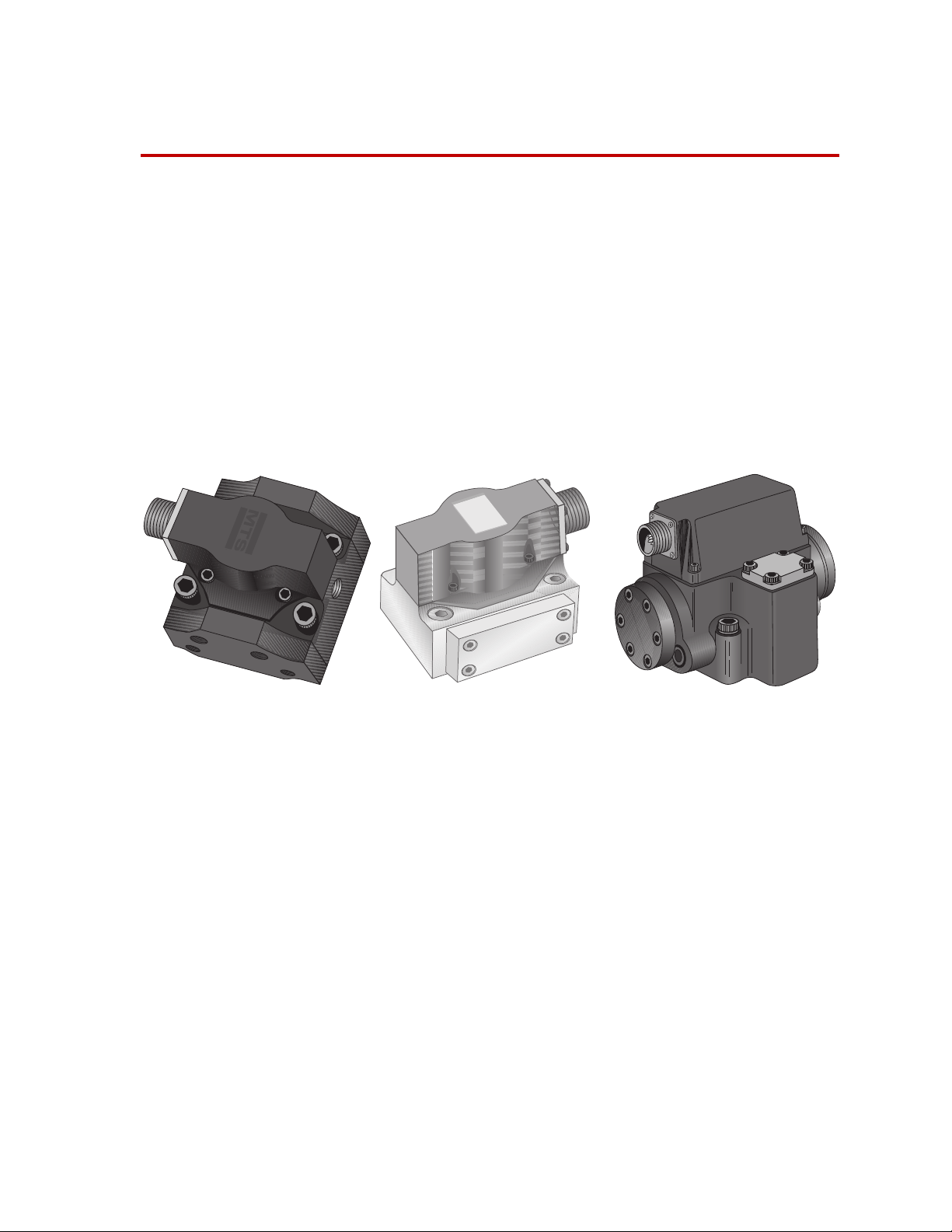
Introduction
Series 252.3x Servovalve
m
m
Revision C Revision G
Contents About the Servovalve 14
The MTS Series 252 Servovalves are designed for use with actuators requiring
3.8 to 227 L/min (1 to 60 gpm) of fluid flow.
Servovalve Function 14
Servovalve Applications 16
252 Servovalve General Specifications 20
252 Servovalve Flow Ratings 21
252 Servovalve Performance Characteristics 22
252 Servovalve Dimensions 23
Series 252.2x/4x Servovalve
Note The Series 252.2x/4x Servovalves are available in two versions. Both
versions are interchangeable and have similar specifications.
Important If you are replacing an existing servovalve and you encounter any
component interference or alignment issues, contact MTS
Technical support. Trying to reposition components without
knowing the ramifications can cause equipment damage.
What you need to
know
Series 252 Servovalve Product Information Introduction
MTS Systems Corporation assumes that you know how to use your controller.
See the appropriate manual for information about performing any controllerrelated step in this manual’s procedures. You are expected to know how to
perform the following procedures.
• Turn hydraulic pressure on and off.
• Select a control mode.
• Manually adjust the actuator position.
• You should have experience installing or servicing servohydraulic
equipment.
13
Page 14

About the Servovalve
Test
Command
Control
Signal
Inner
Loop
Outer
Loop
Manifold
Hydraulic
Power
Unit
Valve Driver
Feedback
Controller
Control
Mode
About the Servovalve
The heart of a servohydraulic system is the servovalve. It is the final control
element in most MTS closed-loop systems. The servovalve responds to
command signals generated by the software and processed by the controller and
output through the valve driver module. The servovalve regulates the direction
and flow of the hydraulic fluid entering the actuator from the hydraulic pressure
ports. The direction that the spools move determines the direction of fluid flow to
the actuator. A pressure difference is what causes the fluid to move.
Servovalve Function
Control signal In a closed-loop hydraulic system, the servovalve uses the control signal from an
Servovalve at rest The servovalve’s controlling element is the torque motor, which receives an
Typical Closed-Loop System
electronic control device (controller) to operate a valve that regulates the
movement of a hydraulic actuator.
The control signal is created by comparing the program command signal (the
desired actuator position) and the feedback signal from a transducer (the actual
actuator position). Any difference between the two is called DC error, which is
the command to the servovalve to supply hydraulic fluid to the actuator until the
desired actuator position is achieved.
electrical input from the controller. A flapper is attached to the armature of the
torque motor. The flapper moves from side to side as the armature moves in
response to control signals from the controller. The flapper assembly is
mechanically attached to the armature. There are two nozzles, one on each side of
the flapper.
Because the nozzle-flapper valve is the first control point of hydraulic fluid, it is
called the first stage. As long as there is no command for actuator motion, the
flapper is centered between the two nozzles.
At the same time, pressurized hydraulic fluid entering the valve is applied
equally to both sides of the spool, which does not move. This is the second stage.
14
Introduction
Series 252 Servovalve Product Information
Page 15

Servovalve Function
First Stage
Armature
Nozzle
Second Stage
Spool
Filter
Manifold
Actuator
Piston
LVDT (inside rod)
Actuator Rod
Pressure
from Power
Fixed Orifice
Feedback Wire
Flapper
Lower Pole
Flexure Tube
Upper Pole
Magnets
Coil
Stopping the spool The feedback wire works like a spring. The spool moves until the feedback wire
Moving the spool A command from the controller causes the armature to rotate clockwise or
Functional Diagram
counterclockwise (depending on the polarity of the command). The command
causes the flapper to block one of the nozzles, which diverts hydraulic flow to
that end of the spool. The spool moves and opens hydraulic pressure to one
control port and the return line to the other control port. The control ports are
connected to each end of the actuator.
torque equals the torque from the magnetic forces. This causes the flapper to
move back toward the centered position. The spool stops at a position where the
feedback wire spring torque equals the torque input current of the command. The
spool position is proportional to the input command current.
Although the pressures are equal on both sides of the spool (so the spool is no
longer moving), control flow from the servovalve keeps the actuator moving.
Series 252 Servovalve Product Information Introduction
15
Page 16

Servovalve Applications
Stopping actuator
movement
Servovalve Applications
When the actuator has moved the desired amount, the valve drive command
decreases to zero. Hydraulic fluid flow to the actuator stops, and so does the
actuator.
Servovalves are suitable for a variety of applications. They may be mounted
directly to a linear or rotary actuator, or single or dual servovalves may be
mounted to a manifold, which in turn is mounted to an actuator.
16
Introduction
Series 252 Servovalve Product Information
Page 17

Single Servovalves
This is a cross section of
a single servovalve
showing how its ports are
aligned. A manifold
realigns the ports to
match a given actuator.
Direct Mounting Manifold Mounting
Manifold
Supply Pressure
Supply Return
To/From
Actuator
Single Servovalves
Single servovalves may be mounted to a manifold or directly to an actuator. The
purpose of a manifold is to adapt the ports of the servovalve to the ports of the
actuator.
Series 252 Servovalve Product Information Introduction
17
Page 18

Dual Servovalves
Manifold
To/From
Actuator
To/From
Actuator
Supply
Return
Supply
Pressure
This is a cross section of dual servovalves mounted to a manifold.
Manifold
To /F r om
Actuator
Supply
Return
Supply
Pressure
To /F r om
Actuator
Dual Servovalves
Dual servovalves are sometimes mounted to a manifold. The manifold is a metal
block that connects the ports of each servovalve to the ports of the actuator.
Mounting two servovalves to a manifold doubles the flow rate.
18
Introduction
Series 252 Servovalve Product Information
Page 19

Three-Stage Servovalves
m
m
m
256
252
A small (252) servovalve may be mounted to a larger (256) servovalve, enabling
the fluid flow from the smaller one to be used to move the spool of the larger one.
This configuration enables the control signal to effectively regulate a flow rate
substantially greater than the full-flow rating of the smaller servovalve.
Three-Stage Servovalves
The Series 252 Servovalve provides the first two stages of the Series 256
Servovalve (a three-stage servovalve).
Series 252 Servovalve Product Information Introduction
19
Page 20

252 Servovalve General Specifications
252 Servovalve General Specifications
Parameter Specification
Maximum operating pressure
Minimum operating pressure 1.4 MPa (200 psi)
Operating temperature range
Revision G only
Rated full-flow input signal current 25 mA (series)
Coil resistance
Seals Viton
Weight
252.2X/.4X Revision C
252.2X/.4X Revision G
252.3X
Hydraulic Fluid
* Higher operating pressures, up to 35 MPa (5000 psi), are available on
request. Contact MTS for further information.
† Do not mix different types or brands of hydraulic fluid. Mixing different
hydraulic fluids can create contaminants and degrade fluid additives. For
information on hydraulic fluid, contact MTS Systems Corporation.
†
31 MPa (4500 psi)
-40°C to +135°C (-40°F to +275°F)
-20°C to +135°C (-40°F to +275°F)
50 mA (differential)
50 mA total (parallel)
80 Ω per coil
1.03 kg (2.3 lb)
0.97 kg (2.1 lb)
3.5 kg (7.5 lb)
Mobil DTE 25 or Shell Tellus 46
*
20
Introduction
Series 252 Servovalve Product Information
Page 21

252 Servovalve Flow Ratings
The following table lists typical flow ratings for the Series 252 Servovalves.
252 Servovalve Flow Ratings
Model
Number
252.21 4.0 L/min (1.0 gpm) 230 Hz 1.10 L/min (031 gpm)
252.22 9.5 L/min (2.5 gpm) 230 Hz 1.44 L/min (0.40 gpm)
252.23 19.0 L/min (5.0 gpm) 230 Hz 2.27 L/min (0.60 gpm)
252.24 37.0 L/min (10.0 gpm) 170 Hz 2.27 L/min (0.60 gpm)
252.25 56.0 L/min (15.0 gpm) 160 Hz 2.27 L/min (0.60 gpm)
252.31 93.0 L/min (25.0 gpm) 80 Hz 5.56 L/min (1.47 gpm)
252.32 151.0 L/min (40.0 gpm) 60 Hz 5.56 L/min (1.47 gpm)
252.33 227.0 L/min (60.0 gpm) 50 Hz 8.33 L/min (2.20 gpm)
252.41 4.0 L/min (1.0 gpm) 300 Hz 1.10 L/min (0.31 gpm)
252.42 9.5 L/min (2.5 gpm) 280 Hz 1.44 L/min (0.40 gpm)
252.43 19.0 L/min (5.0 gpm) 280 Hz 2.27 L/min (0.60 gpm)
* The Model 252.3x servovalves can be converted to external pilot pressure in the field (with auxiliary port).
† Flow ratings are for 7 MPa (1000 psi) pressure drop across the servovalve. Higher flows are available at
‡ The maximum internal null flow is specified at 21 MPa (3000 psi). The null flow at the first stage is 0.76
*
The 90° point is at 10% command.
higher pressure drops.
L/min (0.20 gpm) for all Series 252 Servovalves.
Full-Flow Rating
†
90° point at 10% Command
Null Flow
‡
Series 252 Servovalve Product Information Introduction
21
Page 22

252 Servovalve Performance Characteristics
1
100
10
378
0.1
37
3.7
0.37
1000
100
10
1
Frequency in Hz
Flow in Liters Per Minute
Flow in Gallons Per Minute
252.33
252.32
252.31
1
100
10
378
0.1
37
3.7
0.37
1000
100
10
1
Frequency in Hz
Flow in Liters Per Minute
Flow in Gallons Per Minute
252.43
252.42
252.41
378
37
3.7
0.37
Frequency in Hz
Flow in Liters Per Minute
Flow in Gallons Per Minute
1
100
10
0.1
1000
100
10
1
252.21
252.25
252.24
252.22
252.23
252.2x
252.3x
252.4x
252 Servovalve Performance Characteristics
The flow versus frequency performance curves are shown in the following
figures. They indicate the typical performance capabilities of the servovalves at
various frequencies. The curves are derived by driving the servovalve at the
indicated frequency with a sine wave control signal and ± full current to the coil.
Note Performance in the following graphs are with 21 MPa (3000 psi) pressure
supplied and 7 MPa (1000 psi) pressure drop across the servovalve.
22
Introduction
Flow versus Frequency Performance Curves
Series 252 Servovalve Product Information
Page 23

252 Servovalve Dimensions
Mount with 5/16-18 x 1.50 LG SHCS (4)
(Leaves .38 for THD engagement)
Electrical Connector
Null Adjust Pin
The following figures show the dimensions of the Series 252 Servovalves.
252 Servovalve Dimensions
Model 252.2x/4x Servovalve Dimensions (Revision C)
Model 252.2x/4x Servovalve Dimensions (Revision G)
Series 252 Servovalve Product Information Introduction
23
Page 24

252 Servovalve Dimensions
Model 252.3x Servovalve Dimensions
24
Introduction
Series 252 Servovalve Product Information
Page 25

Installation
252 Servovalve Installation
The servovalve can be installed on an actuator or a Series 256 Servovalve. This
section includes the following:
252 Servovalve Installation 25
252 Servovalve Cable Connections 28
Five-Port Operation—252.2x Servovalve 29
Five-Port Operation—252.3x Servovalve 30
Important If you are replacing an existing servovalve and you encounter any
component interference or alignment issues, contact MTS
Technical support. Trying to reposition components without
knowing the ramifications can cause equipment damage.
252 Servovalve Installation
The actuator has a manifold that aligns the hydraulic ports of the servovalve with
the hydraulic ports on the actuator. Almost all servovalves are installed onto an
adapter manifold. A servovalve may be installed onto an actuator only if the
servovalve ports align with the ports of the actuator.
1. Ensure that system hydraulic pressure has been reduced to zero before
2. Remove the servovalve protective cover plate (attached to the bottom of the
3. Ensure that the O-rings between the servovalve and actuator, manifold, or
4. Position the servovalve on the actuator, manifold, or secondary servovalve,
proceeding. To do this, turn off the hydraulic power unit and exercise the
actuator until it stops moving. Turn off electrical power at the controller.
servovalve). If replacing the servovalve, remove the cover plate from the
actuator.
secondary servovalve are lubricated with a light film of hydraulic fluid and
are in their correct position.
aligning the locating pin on the servovalve with the locating hole on the
actuator, manifold, or secondary servovalve. The servovalve cannot be
installed without proper alignment. See the following figure for the location
of the locating pin.
Series 252 Servovalve Product Information Installation
25
Page 26

252 Servovalve Installation
Locating Pin
Pressure
Port
Control Port No. 2
Mounting Holes
(4 Places)
Return Port
Control Port
No. 1
Pilot Pressure Port
(optional)
Control Port
No. 2
Auxiliary Pilot
Pressure Port
Locating Pin
Control Port No. 1
Mounting Holes
(4 places)
Return Port
Pressure Port
1
2
3
4
Servovalve Locating Pin
Note For mounting the Model 252.2x and 252.4x servovalves use four 5/16-18
x 1-1/2 in. ASTM A574 socket head cap screws and the Model 252.3x
servovalve uses four 3/8-16 x 1-3/4 in. ASTM A574 socket head cap
screws. As the screws are successively tightened, those previously
tightened will lose clamping force. Continue tightening until all screws
are at the specified torque.
5. After lubricating the mounting screws with a light film of oil, tighten each
one until it is firmly seated. Using the sequence shown, tighten the socket
head screws to 5 lbf·ft.
• Continue using the pattern and tighten the socket head screws to a final
torque of 13-19 lbf·ft for 252.2x and 252.4x servovalves.
• Continue using the pattern and tighten the socket head screws to a final
torque of 23-34 lbf·ft torque for 252.3X servovalves.
Note For manifolds machined with metric threads, the requirements are as
follows:
252.2X and 252.4X Servovalves: M8 x 1.25 mm x 40 mm long socket
head cap screws (DIN 912 Class 12.9). Final torque 19-28 N·m.
Installation
26
6. Connect the four-pin electrical cable from the controller to the servovalve.
7. Turn on electrical and hydraulic system power.
252.3X Servovalves: M10 x 1.5 mm x 45 mm long (DIN Class 12.9. Final
torque 36-53 N·m.
Series 252 Servovalve Product Information
Page 27

252 Servovalve Installation
8. Apply low hydraulic pressure to the servovalve so that the hydraulic fluid
gradually fills the filter cavity.
9. Apply high hydraulic pressure and check for leaks at the servovalve
hydraulic connections and at the base of the servovalve.
Series 252 Servovalve Product Information Installation
27
Page 28

252 Servovalve Cable Connections
MTS Controller
backshell
Reverse leads A and D
for servovalves phased
the same hydraulically
Coils
Series
Differential
Parallel
Connector
Drain
valve command2
valve command2
valve command2
valve command1
MTS Controller
backshell
Drain
valve command2
valve command2
valve command2
valve command1
To ta l
Dual
Servovalves
80Ω
80Ω
252 Servovalve Cable Connections
The following figure shows the connector wiring for the servovalve. The correct
wiring configuration is determined by the requirements of the device used to
control the servovalve. See the appropriate controller manual for information on
servovalve connections. Common MTS cables include:
• For a single Model 252 servovalve, part number 397006-xx
• For dual Model 252 servovalves, part number 397007-xx
Wiring Diagrams
28
Installation
Series 252 Servovalve Product Information
Page 29

Five-Port Operation—252.2x Servovalve
Relocate screw and
seal washer to P
port for external (5th
port) pilot oil supply
Location of screw
and seal washer
for standard
internal (4th port)
pilot oil supply
WARNING
The Model 252.2x Servovalve can easily be changed from four to five ports. The
servovalve can be configured for pilot stage oil supply through the internal
pressure “P” port, or from a separate supply line through the “X” port. Standard
configuration is internal pilot operation with a screw and seal washer in the “X”
port. This same screw and seal washer must be relocated to the “P” port if an
external pilot oil supply source is desired. The following figure shows the screw
and seal washer locations.
Five-Port Operation—252.2x Servovalve
Make sure the screw and seal washer are correctly relocated to the P port.
If the screw and seal washer are not correctly relocated to the P port,
pressurized oil from the PP port can make its way to the valve's P port,
which could result in pressurized oil being connected to an actuator even if
the main hydraulic supply is blocked.
This could result in dangerous actuator motion.
Important Some local regulations might require precise hydraulic labeling on
components. Upon valve installation, the nameplate must display
the proper hydraulic schematic and typecode (if applicable). When
a valve is configured for a pilot supply, please attach a lower half
label (available from MTS) showing the external (5th port)
information. An example follows.
Series 252 Servovalve Product Information Installation
29
Page 30

Five-Port Operation—252.3x Servovalve
4 Ports Fifth Port
Five-Port Operation—252.3x Servovalve
The Model 252.3x Servovalve can easily be changed from four to five ports. The
fifth port provides hydraulic pressure to the spool even when station pressure is
removed. The following procedure describes how to open the fifth port and block
a secondary port to the filter.
The five port configuration can be changed back to a four port configuration. Use
the following procedure as a guideline to remove the plug in the secondary filter
port and install it into the fifth port on the bottom of the servovalve.
1. Turn the hydraulic pressure off.
Ensure that system hydraulic pressure has been reduced to zero before
proceeding. To do this, turn off the hydraulic power unit and exercise the
actuator until it stops moving. Then, turn off electrical power to the
controller.
2. Open the fifth port.
A. On a new servovalve, remove the protective cover plate (attached to the
bottom of the servovalve).
On an existing servovalve, remove the servovalve from its mounting.
B. Use a 1/8 inch Allen driver to remove the Allen screw covering the
fifth port
.
C. Inside the port, use a threaded screw driver (#2 -56) to connect to the
inner plug.
D. Pull the threaded plug out of the fifth port.
3. Remove the filter.
E. Remove the four socket head screws and washers that secure the filter
cover plate to the filter housing.
F. Remove the filter cover plate.
Installation
30
G. Remove the filter plug by threading one of the socket head screws,
removed in Step E, into the filter plug and pulling it out of the filter
housing.
H. Remove the filter.
4. Close the secondary filter port.
Series 252 Servovalve Product Information
Page 31

Five-Port Operation—252.3x Servovalve
Secondary filter port
Secondary filter port
1
2
3
4
A. Use the threaded screw driver (#2 -56) to connect to the plug. Push the
plug into the secondary port until it seats into the port
.
B. Remove the threaded screw driver from the plug.
C. Use a 1/8 inch Allen driver to install the Allen set screw removed in
Step B into the secondary filter port.
5. Reassemble the filter.
A. Lightly lubricate the filter O-ring with clean hydraulic fluid and insert
the filter into the housing.
B. Lightly lubricate the filter plug O-rings with clean hydraulic fluid and
install the filter plug.
C. Secure the filter cover plate to the housing using the four socket head
screws and washers removed in Step 3E. Tighten each socket head
screw until it is firmly seated against the filter cover plate. Using the
sequence shown here, tighten the socket head screws to 14 N·m (10
lbf·ft). Continue using the sequence and tighten the socket head screws
to a final torque of 34-41 N·m (25-30 lbf·ft)
D. Turn on electrical and hydraulic system power.
E. Apply low hydraulic pressure to the servovalve so that hydraulic fluid
will gradually fill the filter cavity.
F. Apply high hydraulic pressure and check for leaks at the servovalve
hydraulic connections and at the base of the servovalve.
Series 252 Servovalve Product Information Installation
31
Page 32

Five-Port Operation—252.3x Servovalve
32
Installation
Series 252 Servovalve Product Information
Page 33

Maintenance
Contents Replace the Servovalve Filter Element 33
Replace the Servovalve Filter Element
Maintaining the Series 252 Servovalves typically involves changing the filter
element (Model 252.3x only) and setting the mechanical null adjustment. Except
for these procedures, further disassembly, inspection, or repair of the servovalve
is not recommended and may void the servovalve warranty.
MTS does not recommend changing the 35-micron filter element in the Models
252.2x/.4x Servovalve (revision C). MTS hydraulic power supplies filter the
system hydraulic fluid at 3-microns absolute. The system filters will trap most
solid particle contaminants. If servovalve performance has deteriorated and the
cause has been isolated to the servovalve filter, return the servovalve to MTS for
service.
Adjust the Mechanical Null 35
Troubleshooting Guide 39
Replace the Servovalve Filter Element
Under normal operating conditions, the 20-micron stainless steel filter used in the
servovalve should be replaced only if servovalve performance has deteriorated.
Ensure that other possible causes of poor performance, such as plugged system
filters or hydraulic power unit wear, have been eliminated before replacing the
servovalve filter.
Prerequisites You must have a filter kit that contains the necessary filter element replacement
parts. The filter for the Model 252.3x Servovalves is MTS part number 032-844-
101. The filter for the revision G Model 252.2x/4x servovalves is MTS part
number 100-098-436. MTS does not recommend field replacement of filters in
earlier revision servovalves.
Procedure To replace the filter element, perform the following procedure. Care should be
exercised to prevent dirt or other contaminants from entering the servovalve
body, filter passages, or manifold/actuator ports. Refer to the following figure
during the procedure.
Series 252 Servovalve Product Information Maintenance
33
Page 34

Replace the Servovalve Filter Element
Filter Cover
1
4
3
2
Socket Head
Screws (4)
Filter Cover Plate
Filter Plug
Filter Plug O-Rings
Filter O-Ring
Filter
Filter Housing
Model 252.2x/.4x Filter Location
(Revision G only)
Model 252.3x Filter Assembly
For the Models
252.2x/4x Servovalve
For the Model 252.3x
Servovalve
1. Ensure that system hydraulic pressure has been reduced to zero before
proceeding. To do this, turn off the hydraulic power unit and exercise the
actuator until it stops moving. Turn off electrical power to the controller.
Note This procedure only applies to revision G of the servovalve.
A. Remove the four socket head screws and washers that secure the filter
cover plug.
B. Thread one of the socket head screws, removed in Step A, into the filter
cover plug and pull it out of the filter housing.
C. Remove the filter disk.
D. Insert the new filter into the housing.
E. Secure the filter cover plate to the housing using the four socket head
screws and washers removed in Step A. Using the appropriate
sequence, tighten the socket head screws to 4.5 N·m (40 lb·in).
A. Remove the four socket head screws and washers that secure the filter
cover plate to the filter housing.
Maintenance
34
Series 252 Servovalve Product Information
Page 35

Adjust the Mechanical Null
B. Remove the filter plug by threading one of the socket head screws,
removed in Step A, into the filter plug and pulling it out of the filter
housing. Remove the filter cover plate.
C. Remove the filter plug O-rings from the filter plug.
D. Remove the filter O-ring from the filter.
E. Remove the filter.
F. Lightly lubricate the filter O-ring with clean hydraulic fluid, install it
on the replacement filter, and insert the filter into the housing.
G. Lightly lubricate the filter plug O-rings with clean hydraulic fluid,
install them on the filter plug, and install the filter plug.
H. Secure the filter cover plate to the housing using the four socket head
screws and washers removed in Step A. Tighten each socket head
screw until it is firmly seated against the filter cover plate. Using the
appropriate sequence, tighten the socket head screws to 4.5 N·m (40
lbf·in). Continue using the sequence and tighten the socket head screws
to a final torque of 9.60 N·m (85 lbf·in).
2. Turn on electrical and hydraulic system power.
3. Apply low hydraulic pressure to the servovalve so that hydraulic fluid
4. Apply high hydraulic pressure and check for leaks.
Adjust the Mechanical Null
This procedure describes how to adjust the mechanical null for the Series 252
Servovalve. The mechanical null adjustment aligns the servovalve spool to a
position that results in little or no actuator movement when there is no control
signal.
Prerequisites MTS Systems Corporation recommends that you read this procedure before
attempting to adjust the mechanical null. The mechanical null adjustment is quite
sensitive, and you should be familiar with the hazards that can be encountered
when performing the procedure.
Perform the servovalve mechanical null adjustment after the valve balancing
procedure (electrical compensation) has been completed and the results are
judged unsatisfactory.
During the servovalve mechanical null adjustment procedure, the actuator should
be free to move with minimal load.
Valve balance
adjustments
MTS controllers have an electronic mechanical null adjustment called valve
balance. The valve balance adjustment is a convenient way to compensate for a
servovalve that needs a mechanical null adjustment. The adjustment introduces
an electrical offset signal that causes the servovalve to hold the position of the
actuator when a zero command is issued.
gradually fills the filter cavity.
Series 252 Servovalve Product Information Maintenance
35
Page 36

Adjust the Mechanical Null
WARNING
Do not perform the following procedure without clearing the path of motion
of the actuator.
Sudden and unexpected actuator rod movement can cause serious injury to
personnel and/or damage to equipment.
Ensure that all personnel, specimen/structures, and tools are away from the path
of motion of the actuator (crush zone).
1. Exercise the actuator.
The actuator should be exercised to warm it up. Electrical and mechanical
adjustments are more repeatable after the actuator is warmed up.
A. Select displacement control for the controller.
B. Adjust the actuator for mid-displacement.
C. Turn on electrical and hydraulic system power.
D. Define a 50%, 0.1 Hz sine wave command and allow the actuator to
warm up for approximately one-half hour.
E. After the warm up period, stop the test program.
2. Set up for null-adjustment.
A. Set the supply pressure to the normal operating pressure (typically
3000 psi).
B. The actuator should be in position control, with the reset integrator
disabled or set to zero.
C. Set the electrical valve balance to zero.
D. Monitor both command (actuator displacement command,) and
feedback (actuator position feedback.)
E. For Series 252.2X and older Series 252.3X servovalves with adjuster
pins, follow step 3 below. For newer Series 252.3X servovalves with
the null adjustment screw on the top of the valve cover, follow step 4
below.
3. Setting the adjuster pin. (Series 252.2X and older Series 252.3X
servovalves.)
A. Slightly loosen the self-locking nut.
36
Maintenance
B. Insert a 3/32-inch hex key into the adjustor pin socket. See the
following figure for the location of the adjustor pin.
Series 252 Servovalve Product Information
Page 37

Adjust the Mechanical Null
CAUTION
Series 252.2x, 252.4x, and
252.5x
Servovalves
3/8 inch
Series
252.3x
Servovalve
3/32 inch
3/8 inch
3/32 inch
Adjuster Pin
Adjuster Pin
Scribe mark on adjuster pin
points toward base of
servovalve to mark the
approximate null position.
Self
Locking
Nut
Base
(Side View)
Base
(End View)
Do not apply more than 1.36 N•m (12 lbf-in.) of torquing force to the adjustor
pin.
Excessive torquing may shear off the adjustor pin eccentric.
If the pin does not turn using very little force, gently loosen the self-locking nut
more, then try turning the pin again.
C. Check that the scribe mark on the adjuster pin is pointed toward the
base (oriented in the lower 180° of the adjustment range). If necessary,
rotate the adjuster pin so that the scribe mark is pointed towards the
base.
D. While monitoring the command and feedback signals, slowly rotate the
adjustor pin until command equals feedback.
E. Verify that the scribe on the adjuster pin is pointed approximately
towards the base.
Mechanical Null Adjustor Pin
F. While holding the adjuster pin in position, tighten the self-locking nut
until it is snug, (1.13 to 1.35 N*m, 10 to 12 in*lbf) while monitoring
Series 252 Servovalve Product Information Maintenance
the command and feedback signals to ensure that the command equals
feedback.
37
Page 38

Adjust the Mechanical Null
G. See your controller manual to complete the valve balance procedure.
4. Set the magnetic null adjustment (Newer Series 252.3X servovalves).
A. Using a flat screwdriver, slowly rotate the magnetic null adjustment on
the top of the servovalve while monitoring the command and feedback
signals until the command equals feedback.
B. See your controller manual to complete the valve balance procedure.
38
Maintenance
Series 252 Servovalve Product Information
Page 39

Troubleshooting Guide
The table below provides the symptom, probable cause, and remedy for some
common servovalve malfunctions that may be encountered.
Before diagnosing a servovalve malfunction, ensure that:
• The servovalve is getting the proper command.
• The servovalve is getting full system pressure and flow.
• The hydraulic fluid in the system is clean.
S
YMPTOM PROBABLE CAUSE REMEDY
Troubleshooting Guide
Output flow from only one
control port
Actuator is fully
extended/retracted, or
hydraulic motor is
rapidly rotating
Does not respond to the
command signal
Poor response (the servovalve
output lags command signal)
High null bias
(a large valve balance
adjustment at the controller is
needed to maintain hydraulic
actuator in stationary position)
Plugged inlet filter element Replace filter element (252.3x
Partially plugged filter element Clean inlet orifices or clean/replace
Incorrect (mechanical or
electrical) null adjustment
Partially plugged inlet orifice
assembly
Partially plugged filter element
* For a Series 252.2X or 252.4X Servovalve, return the unit to MTS.
only)*
filter element
(252.3x only);* check for dirty
hydraulic fluid
Adjust null
Clean inlet orifices
Clean/replace filter element (252.3X
only);* check for dirty hydraulic
fluid
Series 252 Servovalve Product Information Maintenance
39
Page 40

Troubleshooting Guide
40
Maintenance
Series 252 Servovalve Product Information
Page 41

Page 42

m
MTS Systems Corporation
14000 Technology Drive
Eden Prairie, Minnesota 55344-2290 USA
Toll Free Phone: 800-328-2255
(within the U.S. or Canada)
Phone: 952-937-4000
(outside the U.S. or Canada)
Fax: 952-937-4515
E-mail: info@mts.com
Internet: www.mts.com
ISO 9001 Certified QMS
 Loading...