


Mitsubishi SE-1.6AR.TH (-T), SE-2AR.TH (-T), SE-2.5AR.TH (-T), SU-1.6VR.TH (-T), SU-2NR.TH Service Manual
...SPLIT-TYPE, AIR CONDITIONERS
No. OC167
REVISED EDITION-A
TECHNICAL & SERVICE MANUAL
Series SE Ceiling Concealed
<Indoor unit> |
<Outdoor unit> |
[Models] SE-1.6AR.TH SE-2AR.TH SE-2.5AR.TH
SE-1.6AR.TH-T
SE-2AR.TH-T
SE-2.5AR.TH-T
SU-1.6NR.TH SU-2NR.TH SU-2.5NR.TH SU-1.6VR.TH SU-2VR.TH SU-2.5VR.TH SU-1.6VR.TH-T SU-2VR.TH-T SU-2.5VR.TH-T
|
|
|
|
|
|
CONTENTS |
|
|
|
|
|
|
1. PART NAMES AND FUNCTIONS ········2 |
|
|
|
|
|
|
2. SPECIFICATIONS·································4 |
|
|
|
|
|
|
3. OUTLINES AND DIMENSIONS············7 |
|
|
|
|
|
|
4. WIRING DIAGRAM·······························9 |
|
|
|
|
|
|
5. REFRIGERANT SYSTEM DIAGRAM ······12 |
|
|
|
|
|
|
6. DATA ···················································16 |
|
|
|
|
|
|
7. MICROPROCESSOR CONTROL·······21 |
INDOOR UNIT |
OUTDOOR UNIT |
8. TROUBLESHOOTING························25 |
||||
|
|
|
|
|
|
9. DISASSEMBLY PROCEDURE···········31 |
|
TIMER TEMP |
TIMER/TEMP. |
POWER |
ON/OFF |
10. PARTS LIST········································36 |
|
|
|
|
|
11. OPTIONAL PARTS ·····························40 |
||
|
12 |
29 |
|
DRY |
SELECT |
|
|
10 |
27 |
|
|||
|
11 |
28 |
|
COOL |
MODE |
|
|
|
|
|
|
|
|
|
9 |
26 |
|
FAN |
|
|
|
8 |
25 |
UP |
HIGH |
FAN |
|
|
7 |
24 |
|
|||
|
|
LOW |
SPEED |
|
||
|
6 |
23 |
|
|
||
|
|
|
|
|
||
|
5 |
22 |
DOWN |
|
|
|
|
4 |
21 |
|
|
|
|
|
3 |
20 |
|
AUTO |
|
|
|
2 |
19 |
|
STOP |
TIMER |
|
|
1 |
18 |
|
START |
MODE |
|
 MITSUBISHI ELECTRIC
REMOTE CONTROLLER
Revision
•SE-1.6AR.TH-T, SE-2AR.TH-T, SE-2.5AR.TH-T, SU-1.6VR.TH, SU-1.6VR.TH-T, SU-2VR.TH, SU-2VR.TH-T,
SU-2.5VR.TH and SU-2.5VR.TH-T are added. •Please destroy OC167, if you have.
The Slim Line.
From Mitsubishi Electric.
1 
 PART NAMES AND FUNCTIONS
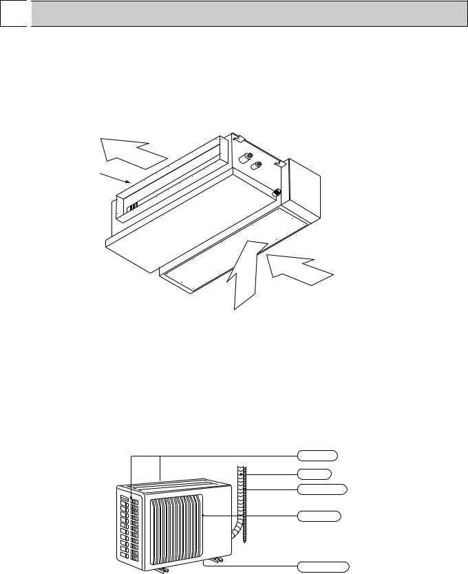
● Indoor Unit
SE-1.6AR.TH SE-2AR.TH SE-2.5AR.TH
SE-1.6AR.TH-T SE-2AR.TH-T SE-2.5AR.TH-T
Air outlet
Air outlet duct flange
intake
(Selecting the either back side or bottom side.)
● Outdoor Unit
SU-1.6NR.TH SU-2NR.TH SU-2.5NR.TH
SU-1.6VR.TH SU-1.6VR.TH-T SU-2VR.TH SU-2VR.TH-T SU-2.5VR.TH SU-2.5VR.TH-T
Air intake
Piping
Drain hose
Air outlet
Drain outlet
2
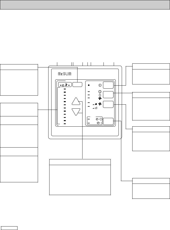
● Remote controller
SE-1.6AR.TH SE-1.6AR.TH-T SE-2AR.TH SE-2AR.TH-T SE-2.5AR.TH SE-2.5AR.TH-T
Settings remain in effect until changed. Air conditioner can be operated by simply pushing ON /OFF button once settings have been made.
|
Display Panel |
|
|
Operating Panel |
|
|
|||||||||
|
|
|
|
|
|
|
|
|
|
|
|
|
|
|
|
|
|
|
|
|
|
|
|
|
|
|
|
|
|
|
|
|
|
|
|
|
|
|
|
|
|
|
|
|
|
|
|
|
|
|
|
|
|
|
|
|
|
|
|
|
|
|
|
TIMER / TEMP.
This button is used to change between display of room temperature and display of remaining timer during "AUTO STOP" operation. Green lamps light in selected display
Lamps display remaining timer time or room temperature.
Remaining timer time display
Lamps indicate time remaining until timer stops timed operation. Green lamps corresponding to remaining number of hours light.
Room Temperature display
Lamps display temperature settings and actual room temperatures.
●Temperature settings; Green lamps light.
●Temperature in room; Green lamps flash.
TIMER |
TEMP TIMER/TEMP. |
POWER |
ON/OFF |
||
|
|
|
|||
12 |
29 |
|
|
|
|
11 |
28 |
|
COOL |
MODE |
|
10 |
27 |
|
DRY |
||
|
SELECT |
||||
9 |
26 |
|
FAN |
||
|
|
||||
8 |
25 |
UP |
HIGH |
FAN |
|
7 |
24 |
||||
|
LOW |
SPEED |
|||
6 |
23 |
|
|||
|
|
|
|||
5 |
22 |
DOWN |
|
|
|
|
|
|
|||
4 |
21 |
|
|
|
|
3 |
20 |
|
AUTO |
|
|
|
STOP |
TIMER |
|||
2 |
19 |
|
|||
|
START |
MODE |
|||
1 |
18 |
|
|||
|
|
|
|||
 MITSUBISHI ELECTRIC
UP and DOWN buttons
●Temperature control (While "TEMP" green lamps is lit.)
Use UP and DOWN buttons to set disired temperature between 18 and 29°C.
●Timed operation (While green "TIMER" lamp is lit.)
Use UP and DOWN buttons to set timed operation between one and twelve hours.
ON / OFF button
Pushing button starts operation. Pushing again stops operation. Green lamp remains lit during
MODE SELECT button
This button is used to change between cooling, ventilation and DRY operation modes. One of three green lamps lights to indicate mode in effect.
FAN SPEED button
This button is used to change between low and high fan speeds. One of two green lamps lights to indicate fan speed in effect.
TIMER MODE button
Used for selecting timed starting or stopping. Green lamps lights to indicate timer mode selected.
(Example display readings are for explanations only ; autual display readings will differ.)
Attention :
●Pushing UP and Down buttons together for more than two seconds will initiate "trial run" or "inspection" mode. Avoid pushing these buttons simultaneously during normal operation. Push ON / OFF button to cancel trial run or inspection mode if initiated by accident.
●All green lamps turn off when air conditioner is stopped.
●Avoid operation of buttons with fingernails or other sharp objects. Sharp objects may scratch operating panel.
3
|
2 |
|
|
SPECIFICATIONS |
|
|
|
|
|||||
|
|
|
|
|
|
|
|
|
|
|
|
|
|
|
|
|
|
|
|
|
|
|
|
|
|
|
|
|
|
|
|
|
Model |
|
|
Indoor unit |
SE -1.6AR.TH |
|
SE -1.6AR.TH SE -1.6AR.TH-T |
|
|
|
|
|
|
|
|
|
|
|
|
|
|
|
|
|
|
|
|
|
|
|
Outdoor unit |
SU -1.6NR.TH |
|
SU -1.6VR.TH SU -1.6VR.TH-T |
|
||
|
|
|
|
|
|
|
|
|
|
||||
|
|
|
|
|
|
|
|
|
|
|
|
||
|
|
|
|
|
Function |
|
Cooling |
|
|||||
|
|
|
|
|
|
|
|
|
|
|
|
|
|
|
|
|
|
|
Power supply |
|
Single phase, 220V, 60Hz |
Single phase, 220-240V, 50Hz |
|
||||
|
|
|
|
|
|
|
|
|
|
|
|
|
|
|
|
|
|
|
Capacity |
|
|
|
W |
3800 |
|
4000 |
|
|
|
|
|
|
|
|
|
|
|
|
|||
|
Capacity |
|
Dehumidification |
R/h |
1.5 |
|
1.6 |
|
|||||
|
|
|
|
|
Air flow |
|
|
|
K/h |
780 |
|
||
|
|
|
|
|
Running current |
A |
6.9 |
|
7.0-6.8 |
|
|||
|
|
|
|
|
|
|
|
|
|
|
|
|
|
|
|
|
|
|
Power input |
W |
1500 |
|
1490-1550 |
|
|||
|
|
|
|
|
|
|
|
|
|
|
|
|
|
|
Electrical |
|
Power factor |
% |
99 |
|
97-95 |
|
|||||
|
|
|
|
|
|
|
|
|
|
|
|||
|
data |
|
Starting current |
A |
36 |
|
35-38 |
|
|||||
|
|
|
|
|
|
|
|
|
|
|
|||
|
|
|
|
|
Compressor motor current |
A |
6.18 |
|
6.41-6.20 |
|
|||
|
|
|
|
|
|
|
|
|
|
|
|
|
|
|
|
|
|
|
Fan motor current |
A |
0.72 |
|
0.59-0.60 |
|
|||
|
Coefficient of performance(C.O.P) |
|
2.53 |
|
2.68-2.58 |
|
|||||||
|
|
|
|
|
|
|
|
|
|
|
|
|
|
|
|
|
|
|
Model |
|
|
|
|
RH-207NHDT |
RH-247VHAT |
|
|
|
|
|
|
|
|
|
|
|
|
|
|||
|
Compressor |
Output |
|
|
|
W |
1000 |
|
1200 |
|
|||
|
|
|
|
|
Winding resistance (at 20:) |
" |
C-R:1.68 C-S:2.78 |
C-R:2.13 C-S:3.91 |
|
||||
|
Indoor |
|
Model |
|
|
|
|
PK6V19-ED |
|
||||
|
|
Winding resistance (at 20:) |
|
WHT-BLK :251.4 |
BLK-BLU : 19.9 |
|
|||||||
|
fan motor |
|
" |
|
|||||||||
|
|
BLU-YLW :26.5 |
YLW-RED :63.2 |
|
|||||||||
|
|
|
|
|
|
|
|
|
|
|
|||
|
|
|
|
|
|
|
|
|
|
|
|
|
|
|
Outdoor |
|
Model |
|
|
|
|
RA6V40-EE |
|
||||
|
|
|
|
|
|
|
|
|
|
|
|||
|
|
Winding resistance (at 20:) |
|
WHT-BLK :130.4 |
|
||||||||
|
fan motor |
|
|
|
|||||||||
|
|
" |
BLK-RED :134.6 |
|
|||||||||
|
|
|
|
|
|
|
|
|
|
|
|||
|
|
|
|
|
|
|
|
|
|
|
|
|
|
|
|
|
|
|
|
|
Width |
mm |
1100 |
|
|||
|
|
|
|
|
Indoor unit |
|
Height |
mm |
270 |
|
|||
|
Dimensions |
|
|
Depth |
mm |
700 |
|
||||||
|
|
|
Width |
mm |
850 |
|
|||||||
|
|
|
|
|
|
|
|
||||||
|
|
|
|
|
|
|
|
|
|
|
|
||
|
|
|
|
|
Outdoor unit Height |
mm |
605 |
|
|||||
|
|
|
|
|
|
|
|
|
|
|
|
|
|
|
|
|
|
|
|
|
Depth |
mm |
290 |
|
|||
|
Weight |
|
Indoor unit |
|
|
|
kg |
35 |
|
|
|||
|
|
Outdoor unit |
kg |
38 |
|
|
|||||||
|
|
|
|
|
|
|
|||||||
|
|
|
|
|
Sound level |
|
Indoor unit |
dB |
35 |
|
|
||
|
|
|
|
|
(Hi) |
|
|
|
|
|
|
|
|
|
|
|
|
|
|
Outdoor unit |
dB |
51 |
|
50 |
|
||
|
|
|
|
|
Fan speed |
|
Indoor unit |
rpm |
740 |
|
720-770 |
|
|
|
|
|
|
|
(Hi) |
|
Outdoor unit |
rpm |
820 |
|
780-820 |
|
|
|
Special |
|
Fan speed |
|
Indoor unit |
|
2 |
|
|
||||
|
remarks |
|
regulator |
|
|
|
|
|
|
|
|
||
|
|
|
Outdoor unit |
|
1 |
|
|
||||||
|
|
|
|
|
|
|
|
|
|
|
|
||
|
|
|
|
|
Refrigerant filling capacity(R-22) |
kg |
0.9 |
|
|
||||
|
|
|
|
|
Refrigerant oil |
R |
MS-56 O 0.52 |
|
|||||
|
|
|
|
|
|
|
RT11(at 25:) |
k" |
10 |
|
|
||
|
|
|
|
|
Thermistor |
|
RT12(at 25:) |
k" |
10 |
|
|
||
|
|
|
|
|
|
|
RT61(at 0:) |
k" |
33.18 |
|
|||
|
NOTE:Test conditions (JIS) |
|
|
|
|
|
|||||||
|
|
Cooling : Indoor |
DB27°C WB19°C |
|
|
|
|
|
|||||
|
|
|
|
|
Outdoor |
DB35°C WB24°C |
|
|
|
|
|
||
4
|
|
|
|
|
|
|
|
|
|
|
|
|
|
|
|
|
|
|
|
|
|
Model |
|
|
Indoor unit |
SE -2AR.TH |
|
SE -2AR.TH SE -2AR.TH-T |
|
|
|
|
|
Outdoor unit |
SU -2NR.TH |
|
SU -2VR.TH SU -2VR.TH-T |
||
|
|
|
|
|
|
||||
|
|
|
|
|
|
|
|
||
|
|
Function |
|
Cooling |
|||||
|
|
|
|
|
|
|
|
|
|
|
|
Power supply |
|
Single phase, 220V, 60Hz |
Single phase, 220-240V, 50Hz |
||||
|
|
|
|
|
|
|
|
|
|
|
|
Capacity |
|
|
|
W |
5900 |
|
5600 |
|
|
|
|
|
|
|
|
||
|
Capacity |
Dehumidification |
R/h |
2.6 |
|||||
|
|
Air flow |
|
|
|
K/h |
1020 |
||
|
|
Running current |
A |
11.5 |
|
10.4-10.2 |
|||
|
|
|
|
|
|
|
|
|
|
|
|
Power input |
W |
2500 |
|
2250-2350 |
|||
|
|
|
|
|
|
|
|
|
|
|
Electrical |
Power factor |
% |
99 |
|
98-96 |
|||
|
|
|
|
|
|
|
|
|
|
|
data |
Starting current |
A |
55 |
|
51-55 |
|||
|
|
|
|
|
|
|
|
|
|
|
|
Compressor motor current |
A |
10.66 |
|
9.73-9.51 |
|||
|
|
|
|
|
|
|
|
|
|
|
|
Fan motor current |
A |
0.84 |
|
0.67-0.69 |
|||
|
Coefficient of performance(C.O.P) |
|
2.36 |
|
2.49-2.38 |
||||
|
|
|
|
|
|
|
|
|
|
|
|
Model |
|
|
|
|
NH-33NCDT |
NH-38VMDT |
|
|
|
|
|
|
|
|
|
|
|
|
Compressor |
Output |
|
|
|
W |
1500 |
|
1700 |
|
|
|
|
|
|
|
|
|
|
|
|
Winding resistance (at 20:) |
" |
C-R:0.92 C-S:1.93 |
C-R:1.07 C-S:2.26 |
||||
|
Indoor |
Model |
|
|
|
|
PK6V32-ED |
||
|
Winding resistance (at 20:) |
|
WHT-BLK :161.9 |
BLK-BLU : 50.3 |
|||||
|
fan motor |
" |
|||||||
|
BLU-YLW :18.7 |
YLW-RED :47.2 |
|||||||
|
|
|
|
|
|
|
|||
|
|
|
|
|
|
|
|
|
|
|
Outdoor |
Model |
|
|
|
|
RA6V50-OF |
||
|
|
|
|
|
|
|
|
|
|
Winding resistance (at 20:) |
|
WHT-BLK :116.4 |
|||||||
|
fan motor |
" |
|||||||
|
BLK-RED :111 |
||||||||
|
|
|
|
|
|
|
|||
|
|
|
|
|
|
|
|
|
|
|
|
|
|
Width |
mm |
1100 |
|||
|
|
|
|
|
|
|
|
|
|
|
|
Indoor unit |
|
Height |
mm |
270 |
|||
|
Dimensions |
|
|
Depth |
mm |
700 |
|||
|
|
|
Width |
mm |
850 |
||||
|
|
|
|
||||||
|
|
Outdoor unit Height |
mm |
605 |
|||||
|
|
|
|
Depth |
mm |
290 |
|||
|
Weight |
Indoor unit |
|
|
|
kg |
35 |
|
|
|
Outdoor unit |
kg |
55 |
|
|||||
|
|
|
|||||||
|
|
Sound level |
|
Indoor unit |
dB |
39 |
|
||
|
|
(Hi) |
|
Outdoor unit |
dB |
53 |
|
52 |
|
|
|
Fan speed |
|
Indoor unit |
rpm |
890 |
|
810-850 |
|
|
|
(Hi) |
|
Outdoor unit |
rpm |
860 |
|
810-845 |
|
|
Special |
Fan speed |
|
Indoor unit |
|
2 |
|
||
|
remarks |
regulator |
|
|
|
|
|
|
|
|
|
Outdoor unit |
|
1 |
|
||||
|
|
|
|
|
|
|
|
||
|
|
Refrigerant filling capacity(R-22) |
kg |
1.65 |
|
1.6 |
|||
|
|
Refrigerant oil |
R |
MS-32(N-1) O 0.85 |
|
MS-32(N-1) O 1.2 |
|||
|
|
|
|
RT11(at 25:) |
k" |
10 |
|
||
|
|
Thermistor |
|
RT12(at 25:) |
k" |
10 |
|
||
|
|
|
|
RT61(at 0:) |
k" |
33.18 |
|||
|
NOTE:Test conditions(JIS) |
|
|
|
|
||||
|
Indoor DB27°C WB19°C |
|
|
|
|
||||
|
Outdoor DB35°C WB24°C |
|
|
|
|
||||
|
|
|
|
|
|
|
|
||
|
Capacity |
|
Capacity |
W |
5200 |
|
— |
||
|
Electrical |
|
Current |
A |
13.1 |
|
— |
||
|
Data |
|
Input |
W |
2850 |
|
— |
||
NOTE:Test condition(SSA 385/386)
Indoor DB29˚C WB19˚C
Outdoor DB46˚C WB24˚C
WSSA 385/386 can be applied only to Saudi Arabia. |
5 |

|
|
|
|
|
|
|
|
|
|
|
|
|
|
|
|
|
|
|
|
|
|
|
|
Model |
|
|
Indoor unit |
SE -2.5AR.TH |
|
SE -2.5AR.TH SE -2.5AR.TH-T |
|
|
|
|
|
|
|
|
|
|
|
|
|
|
|
|
|
Outdoor unit |
SU -2.5NR.TH |
|
SU -2.5VR.TH SU -2.5VR.TH-T |
|
||
|
|
|
|
|
|
|
||||
|
|
|
|
|
|
|
|
|
||
|
|
Function |
|
Cooling |
|
|||||
|
|
|
|
|
|
|
|
|
|
|
|
|
Power supply |
|
Single phase, 220V, 60Hz |
Single phase, 220-240V, 50Hz |
|
||||
|
|
|
|
|
|
|
|
|
|
|
|
|
Capacity |
|
|
|
W |
7000 |
|
6600 |
|
|
|
|
|
|
|
|
|
|
||
|
Capacity |
Dehumidification |
R/h |
3.2 |
|
|||||
|
|
|
|
|
|
|
|
|
|
|
|
|
Air flow |
|
|
|
K/h |
1200 |
|
||
|
|
|
|
|
|
|
|
|
|
|
|
|
Running current |
A |
13.6 |
|
14.0-13.2 |
|
|||
|
|
|
|
|
|
|
|
|
|
|
|
|
Power input |
|
|
|
W |
2920 |
|
3030-3050 |
|
|
|
|
|
|
|
|
|
|
|
|
|
Electrical |
Power factor |
|
|
|
% |
98 |
|
98-96 |
|
|
|
|
|
|
|
|
|
|
|
|
|
data |
Starting current |
A |
56 |
|
59 |
|
|||
|
|
|
|
|
|
|
|
|
|
|
|
|
Compressor motor current |
A |
12.52 |
|
13.11-12.26 |
|
|||
|
|
|
|
|
|
|
|
|
|
|
|
|
Fan motor current |
A |
1.08 |
|
0.89-0.94 |
|
|||
|
Coefficient of performance(C.O.P) |
|
2.40 |
|
2.18-2.16 |
|
||||
|
|
|
|
|
|
|
|
|
|
|
|
|
Model |
|
|
|
|
NH-38NBDT |
NH-47VMDT |
|
|
|
|
|
|
|
|
|
|
|
|
|
|
Compressor |
Output |
|
|
|
W |
1700 |
|
2200 |
|
|
|
Winding resistance (at 20:) |
" |
C-R:0.83 C-S:1.83 |
C-R:0.96 C-S:2.07 |
|
||||
|
Indoor |
Model |
|
|
|
|
PK6V50-ED |
|
||
|
Winding resistance (at 20:) |
|
WHT-BLK :101.1 |
BLK-BLU : 56.1 |
|
|||||
|
fan motor |
" |
|
|||||||
|
BLU-YLW :14.7 |
YLW-RED :34.9 |
|
|||||||
|
|
|
|
|
|
|
|
|||
|
|
|
|
|
|
|
|
|
|
|
|
Outdoor |
Model |
|
|
|
|
RA6V60-AB |
|
||
|
|
|
|
|
|
|
|
|
|
|
|
Winding resistance (at 20:) |
|
WHT-BLK :81.1 BLK-YLW :92.2 |
|
||||||
|
fan motor |
" |
|
|||||||
|
YLW-RED :102.2 |
|
||||||||
|
|
|
|
|
|
|
|
|||
|
|
|
|
|
|
|
|
|
|
|
|
|
|
|
Width |
mm |
1100 |
|
|||
|
|
Indoor unit |
|
Height |
mm |
270 |
|
|||
|
Dimensions |
|
|
Depth |
mm |
700 |
|
|||
|
|
|
Width |
mm |
850 |
|
||||
|
|
|
|
|
||||||
|
|
Outdoor unit |
|
Height |
mm |
605 |
|
|||
|
|
|
|
Depth |
mm |
290 |
|
|||
|
Weight |
Indoor unit |
|
|
|
kg |
35 |
|
|
|
|
Outdoor unit |
|
|
|
kg |
61 |
|
|
||
|
|
|
|
|
|
|
||||
|
|
Sound level |
|
Indoor unit |
dB |
43 |
|
|
||
|
|
(Hi) |
|
Outdoor unit |
dB |
54 |
|
53 |
|
|
|
|
Fan speed |
|
Indoor unit |
rpm |
980 |
|
860-890 |
|
|
|
|
(Hi) |
|
Outdoor unit |
rpm |
930 |
|
860-890 |
|
|
|
Special |
Fan speed |
|
Indoor unit |
|
2 |
|
|
||
|
remarks |
regulator |
|
|
|
|
|
|
|
|
|
|
Outdoor unit |
|
2 |
|
|
||||
|
|
|
|
|
|
|
|
|||
|
|
Refrigerant filling capacity(R-22) |
kg |
2.15 |
|
|||||
|
|
Refrigerant oil |
|
|
|
R |
MS-32(N-1) O 1.2 |
|
||
|
|
|
|
RT11(at 25:) |
k" |
10 |
|
|
||
|
|
Thermistor |
|
RT12(at 25:) |
k" |
10 |
|
|
||
|
|
|
|
RT61(at 0:) |
k" |
33.18 |
|
|||
|
NOTE:Test conditions(JIS) |
|
|
|
|
|
||||
|
Indoor DB27°C WB19°C |
|
|
|
|
|
||||
|
Outdoor DB35°C WB24°C |
|
|
|
|
|
||||
|
|
|
|
|
|
|
|
|||
|
Capacity |
Capacity |
W |
6100 |
|
— |
|
|||
|
|
|
|
|
|
|
|
|||
|
Electrical |
Current |
A |
16.2 |
|
— |
|
|||
|
Data |
|
Input |
W |
3490 |
|
— |
|
||
NOTE:Test condition(SSA 385/386)
Indoor DB29˚C WB19˚C
Outdoor DB46˚C WB24˚C
6 |
WSSA 385/386 can be applied only to Saudi Arabia. |
|
, SE-2AR.TH (-T), SE-2.5AR.TH (-T), SU-1.6VR.TH (-T), SU-2NR.TH Service Manual")
3 OUTLINES AND DIMENSIONS
SE-1.6AR.TH SE-1.6AR.TH-T SE-2AR.TH SE-2AR.TH-T SE-2.5AR.TH SE-2.5AR.TH-T
INDOOR UNIT
Air intake
Electrical parts box
Suspension bolt pitch
Air outlet Access door
Suspension bolt pitch
Unit : mm
|
|
Electrical |
||
|
|
parts |
20 mm or more |
|
Suspension bolt pitch |
box |
|||
|
||||
|
|
A |
|
|
View A |
Refrigerent pipe(liquid) |
Access door |
||
Refrigerent pipe(gas) |
|
|
||
{12.7(SE-1.6AR.TH) |
{6.35(SE-1.6/2AR.TH) |
|
|
|
(SE-1.6AR.TH-T) |
(SE-1.6/2AR.TH-T) |
|
||
{15.88(SE-2/2.5AR.TH) {9.52(SE-2.5AR.TH) |
|
|
||
(SE-2/2.5AR.TH-T) |
(SE-2.5AR.TH-T) |
|
|
|
Service space(It is
necessary to maintain Drain plug R1 male a working service
area from the ceiling.)
SU-1.6NR.TH SU-1.6VR.TH SU-1.6VR.TH-T SU-2NR.TH SU-2VR.TH SU-2VR.TH-T SU-2.5NR.TH SU-2.5VR.TH SU-2.5VR.TH-T
OUTDOOR UNIT
350 |
20 |
|
|
35 |
|
|
|
248 |
290 |
310 |
345 |
Drainage |
|
3holes 16.2 |
30 |
605
292 |
|
|
|
|
|
|
|
157 |
100 |
20 |
50 |
133 |
|
|
|
500 |
|
|
|
|
|
74 |
|
|
|
|
850 |
|
|
|
|
|
|
|
|
|
|
sides |
|
|
|
|
|
|
|
right/left |
only |
|||
|
|
|
|
|
|
. |
||||
|
|
|
|
|
|
|
|
|
has |
|
|
thefront |
|
|
unobstructed |
||||||
|
|
|
|
|
or |
the |
top |
|
|
|
|
|
|
vacant, |
|
|
|
||||
|
If |
|
|
|
|
|
|
|||
more |
are |
be |
10cm |
|
|
|
|
|||
|
|
|
|
|
|
|
||||
or |
|
to |
|
|
|
|
|
|
|
|
10cm |
|
|
|
|
|
|
more |
|
|
|
|
|
|
|
|
or |
|
|
|
||
|
|
|
|
10cm |
|
|
|
|
||
10cm |
or |
|
more |
|
ore |
|
|
|
|
m |
|
|
|
|
or |
|
|
|
|
50cm |
35cm |
|
|
|
If the right/left sides or |
or |
m |
|
|
|
|||
|
|
|
|
|
|
back side is vacant,the |
|
|
ore |
|
|
|
|
|
|
front has only to be 50cm |
|
|
|
|
unobstructed. |
|
|
|
|
Service panel |
|
|
|
|
Liquid refrigerant |
|
|
|
|
pipe joint |
|
|
|
|
Refrigerant pipe |
|
|
|
|
(flare) |
|
|
|
30 |
6.35 (SU-1.6/2NR.TH) |
|
|
|
|
(SU-1.6/2VR.TH,SU-1.6/2VR.TH-T) |
|||
35 |
9.52 (SU-2.5NR.TH) |
|
|
|
(SU-2.5VR.TH,SU-2.5VR.TH-T) Gas refrigerant
pipe joint
161
Refrigerant pipe
(flare)
 12.7 (SU-1.6NR.TH) (SU-1.6/2VR.TH,SU-1.6/2VR.TH-T)
 15.88 (SU-2/2.5NR.TH) (SU-2/2.5VR.TH,SU-2/2.5VR.TH-T)
7
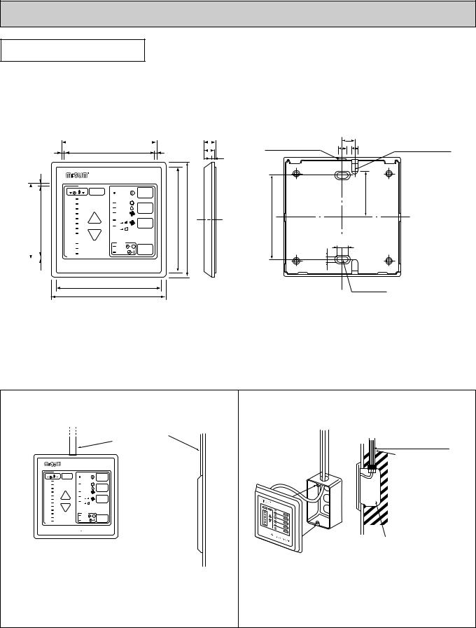
REMOTE CONTROLLER
Unit : mm
3
75 |
69 |
||
|
|
|
|
|
|
|
|
|
|
3 |
|
|
96.5 |
|
12 |
|
||
|
|
|
|
|
|
|
3 |
90.5 |
3 |
11.6 |
|
||
|
|
|
|
|||
3.6
TIMER |
TEMP TIMER/TEMP. |
POWER |
ON/OFF |
|
||
12 |
29 |
|
|
|
|
|
11 |
28 |
|
COOL |
MODE |
|
|
10 |
27 |
|
DRY |
|
||
|
SELECT |
|
||||
9 |
26 |
|
FAN |
|
||
|
|
|
||||
8 |
25 |
UP |
HIGH |
FAN |
108 117 |
|
7 |
24 |
|||||
|
LOW |
SPEED |
||||
6 |
23 |
|
||||
|
|
|
|
|||
5 |
22 |
DOWN |
|
|
|
|
|
|
|
|
|||
4 21
21
3 |
20 |
AUTO |
2 |
19 |
STOP |
TIMER |
|
START |
MODE |
|||
1 |
18 |
|||
|
|
 MITSUBISHI ELECTRIC
108
117
Upper side wiring |
|
12 |
arrangement |
|
|
|
|
|
opening |
8 |
6 |
|
||
|
|
46 |
83.5
4.6 |
9.2 |
|
Fixing hole
Rear side wiring arrangememt opening
Remote controller cable installation
●For exposed remote controller cable installation
|
|
|
|
Exposed remote controller |
|
|
|
|
|
cable |
|
TIMER |
TEMP TIMER/TEMP. |
POWER |
ON/OFF |
||
|
|
|
|||
12 |
29 |
|
|
|
|
11 |
28 |
|
COOL |
MODE |
|
10 |
27 |
|
DRY |
||
|
SELECT |
||||
9 |
26 |
|
FAN |
||
|
|
||||
8 |
25 |
UP |
HIGH |
FAN |
|
7 |
24 |
||||
|
LOW |
SPEED |
|||
6 |
23 |
|
|||
|
|
|
|||
5 |
22 |
DOWN |
|
|
|
|
|
|
|||
4 |
21 |
|
|
|
|
3 |
20 |
|
AUTO |
|
|
2 |
19 |
|
STOP |
TIMER |
|
|
|
||||
1 |
18 |
|
START |
MODE |
|
|
|
|
|||
 MITSUBISHI ELECTRIC
 Cable can be connected only to the top of the remote controller.
(Right side, left side, and buttom are not possible.)
●For recessed remote controller cable installation
Remote controller cable
Conduit tube
(local arrangement)
Switch box
(local arrangement)
Set screw (match with switch box), local arrangement.
Note : The cable for the remote controller has 10m (39ft) length and 12-core with connectors O.D. 5.8.
8
4 
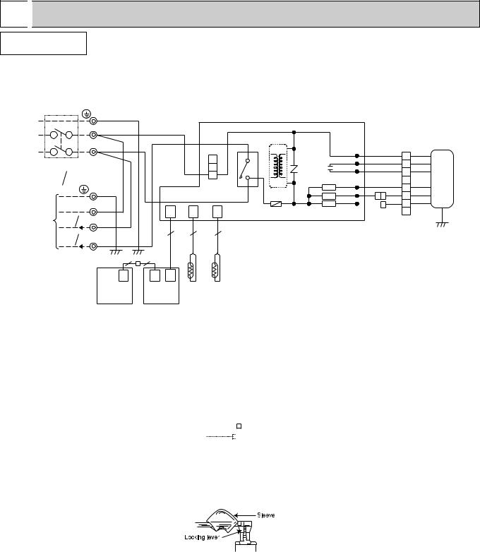
 WIRING DIAGRAM
INDOOR UNIT
SE-1.6AR.TH SE-1.6AR.TH-T
SE-2AR.TH SE-2AR.TH-T
SE-2.5AR.TH SE-2.5AR.TH-T
CIRCUIT BREAKER |
TB |
|
|
|
|
|
|
|
|
|
|
|||
|
GRN/YLW |
|
|
|
|
|
|
|
|
|
||||
|
|
|
|
|
|
|
|
|
|
|
|
|
||
|
|
N |
|
W BLU |
|
|
|
|
|
|
|
|
|
|
|
|
L |
|
W BRN |
|
|
|
|
HIC1 |
|
|
|
|
|
|
|
|
|
|
|
W4 |
|
|
|
LDCOM |
|
|||
|
|
|
|
|
|
|
|
3 |
|
|
|
|
||
POWER SUPPLY |
|
|
|
|
|
NR11 |
C11 |
LDC11 |
|
|||||
220-240V 220V |
|
|
|
|
|
1 |
W 3 |
|
|
|
||||
~/N |
|
|
|
|
|
|
|
2 |
|
52C |
|
LDC12 |
|
|
50Hz |
60Hz TB |
|
|
|
CN201 |
|
TRANS |
|
SR144 LDFH |
BLU |
||||
|
|
|
GRN/YLW |
|
|
|
|
F11 |
|
|
LDFL |
|||
|
|
|
|
|
|
|
|
|
|
|
SR142 |
|
||
|
|
|
NW |
|
|
|
|
|
|
|
|
LDFM |
|
|
|
|
|
BLU |
CN |
CN |
CN |
|
|
|
SR143 |
|
|||
|
|
|
|
|
|
|
|
|
||||||
TO OUTDOOR |
|
|
|
|
ELECTRONIC CONTROL P.C BOARD |
|
||||||||
220-240V 220V |
2 |
|
|
104 |
113 |
112 |
|
|||||||
UNIT |
W WHT |
|
|
|
|
|
|
|
|
|
||||
CONNECTING |
50Hz |
60Hz |
|
|
|
|
|
|
|
|
|
|
||
|
|
|
|
|
|
|
|
|
|
|
|
|
|
|
220-240V 220V |
3 |
W RED |
|
5 |
2 |
2 |
50Hz 60Hz |
|
|
|
|
|
|
|
|
12 |
12 |
|
|
|
|
|
CNR |
CN |
CN |
|
|
|
|
120 |
120 |
104B |
|
|
|
|
REMOTE |
REMOTE |
|
RT11 |
RT12 |
|
|
CONTROLLER |
||||
CONTROLLER |
INTERFACE |
|
P.C BOARD |
||
P.C BOARD |
||
|
WHT |
1 |
WHT |
|
ORN |
ORN |
|
|
RED |
2 |
RED |
|
|
3 |
|
MF |
BLK |
7 |
BLK |
|
4 |
|
||
YLW |
5 |
YLW |
|
BLU |
6 |
BLU |
|
|
8 |
GRN/YLW |
|
|
|
||
SYMBOL |
NAME |
SYMBOL |
NAME |
SYMBOL |
NAME |
|
|
|
|
|
|
C11 |
FAN MOTOR CAPACITOR |
MF |
FAN MOTOR |
RT12 |
INDOOR COIL THERMISTOR |
|
|
|
|
|
|
F11 |
FUSE(3.15A) |
NR11 |
VARISTOR |
SR141 |
SOLID STATE RELAY |
~ |
|||||
|
|
|
|
SR144 |
|
HIC1 |
DC/DC CONVERTER |
RT11 |
ROOM TEMPERATURE THERMISTOR |
TB |
TERMINAL BLOCK |
|
|
|
|
|
|
52C |
COMPRESSOR CONTACTOR |
|
|
|
|
|
|
|
|
|
|
NOTE :1. Since the indoor fan motor (MF) is connected with 50 Hz power, if 60Hz power is used,change the wiring
connection showing fig:*1 |
fig: *1 |
|
|
50 |
YELLOW |
|||
Indoor Fan Moter(MF) for 60Hz |
|
|
|
|
|
|
|
|
|
|
|
|
|
|
|
|
|
BLUE |
|
|
|
|
60 |
BLUE |
||
2.About the outdoor side electric wiring referto the outdoor unit electric wiring diagram for servicing.
3.Use copper conductors only. (For field wiring)
4.Symbols below indicate.
/:Terminal block, |
|
|
|
|
: Connector |
|
|
|
|
How to remove the terminals shown at ”W” mark.
”W” shows the terminals with a lock mechanism,so they cannot be removed when you pull the lead wire. Be sure to pull the wire by pushing the locking lever (project part) of the terminal with a finger.
1Slide the sleeve.
2Pull the wire while pushing the locking lever.
9
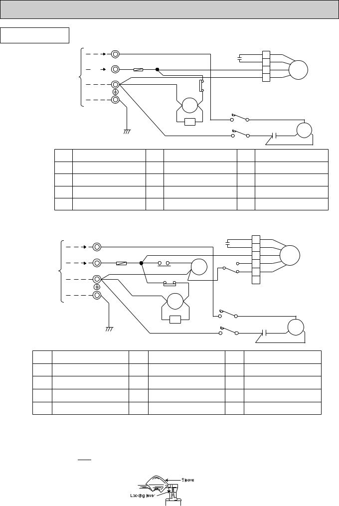
OUTDOOR UNIT
|
|
TB |
|
|
|
|
|
|
|
|
|
|
|
|
|
|
|
SU-1.6NR.TH |
220V, 60Hz |
2 W |
|
|
WHT |
|
|
|
|
|
RED |
|
RED |
|
|
|
|
|
|
|
|
|
|
|
|
|
1 |
|
|
|
|||||
|
|
|
|
|
|
|
|
C2 |
|
|
|
|
|||||
SU-2NR.TH |
|
3 W RED |
|
|
|
|
|
|
ORN |
2 |
ORN |
|
|
|
|||
220V, 60Hz |
F |
RED |
TB2 |
|
|
|
|
|
MF |
|
|||||||
TO INDOOR UNIT CONNECTING |
|
|
|
|
|
BLK |
|
|
|
|
WHT |
3 |
WHT |
|
|
||
|
N |
|
|
|
|
|
|
|
|
BLU |
4 |
BLK |
|
|
|
||
|
W |
BLU |
|
|
|
|
|
|
|
|
|
|
|||||
|
|
|
|
|
|
BLK 26C |
|
|
|
|
|
|
|
|
|||
|
|
|
|
|
|
|
|
|
|
|
|
|
|
|
|||
|
|
|
|
|
|
|
|
|
|
|
|
|
|
|
|
||
|
|
|
|
|
|
|
A2 |
52C |
A1 |
52C |
|
|
|
|
|
|
|
|
|
|
GRN/YLW |
|
|
|
|
|
|
|
|
|
|
|
|
||
|
|
|
|
|
|
|
CR |
|
|
|
|
|
WHT |
|
|
|
|
|
|
|
|
|
|
VLT |
YLW |
L1/1 |
T1/2 |
|
|
|
C |
|
|||
|
|
|
|
|
|
|
|
|
|
|
|
||||||
|
|
|
|
|
|
|
|
|
|
|
|
C1 |
|
S |
MC |
R |
|
|
|
|
|
|
|
|
|
BLU |
|
|
|
BLU |
RED |
||||
|
|
|
|
|
|
|
|
|
|
L3/5 |
T3/6 |
|
BLK |
|
|
|
|
|
|
|
|
|
|
|
|
|
|
|
|
|
|
|
|
|
|
SYMBOL |
NAME |
|
|
|
SYMBOL |
NAME |
|
SYMBOL |
|
NAME |
|
||||||
CR |
SURGE ABSORBER |
|
|
MC |
COMPRESSOR |
|
52C |
COMPRESSOR CONTACTOR |
|||||||||
|
|
(INNER THERMOSTAT) |
|||||||||||||||
|
|
|
|
|
|
|
|
|
|
|
|
|
|
||||
C1 |
COMPRESSOR CAPACITOR |
MF |
FAN MOTOR |
26C THERMAL SWITCH |
|
(INNER THERMOSTAT) |
|||||
|
|
|
|
||
C2 |
FAN MOTOR CAPACITOR |
TB |
TERMINAL BLOCK |
|
|
F |
FUSE(2A) |
TB2 |
TERMINAL BLOCK |
|
SU-2.5NR.TH
CONNECTING
UNIT
TO INDOOR
|
TB |
|
|
220V, 60Hz |
2 |
W |
WHT |
|
|
||
220V, 60Hz |
3 |
W RED F RED |
|
|
N W |
|
|
GRN/YLW
|
|
|
|
|
C2 |
|
RED |
1 |
RED |
|
|
|
|
|
|
ORN |
2 |
ORN |
|
|
|
|
|
|
|
|
|||
|
|
|
|
|
|
|
WHT 3 |
WHT |
|
RED |
|
RED |
8 |
|
|
3 |
|
|
MF |
|
|
5 |
BLK |
4 |
BLK |
||||
|
|
|
|
|
|||||
TB2 |
|
|
7 |
X1 |
|
|
YLW |
|
YLW |
26F1 |
BLU |
|
|
|
X1 1 |
5 |
|||
|
|
|
|
ORN |
|
|
|||
BLK 26C BLK |
|
|
|
6 |
|
||||
|
|
|
|
|
|||||
BLU |
|
|
|
|
|
|
|
|
|
A2 |
52C |
A1 |
|
52C |
|
|
|
||
|
|
|
|
|
|
|
WHT |
||
|
|
|
|
|
|
|
|
|
|
VLT |
|
CR |
YLW |
|
L1/1 |
T1/2 |
|
|
C |
|
|
BLU |
|
|
|
|
BLU C1 |
RED S MC R |
|
|
|
|
|
|
L3/5 |
T3/6 |
|
BLK |
|
|
|
|
|
|
|
|
|
|
|
SYMBOL |
NAME |
SYMBOL |
NAME |
SYMBOL |
NAME |
|
CR |
SURGE ABSORBER |
MC |
COMPRESSOR |
X1 |
FAN MOTOR RELAY |
|
(INNER THERMOSTAT) |
||||||
|
|
|
|
|
||
C1 |
COMPRESSOR CAPACITOR |
MF |
FAN MOTOR |
26F1 |
THERMAL REED SWITCH |
|
(INNER THERMOSTAT) |
||||||
|
|
|
|
|
||
C2 |
FAN MOTOR CAPACITOR |
TB |
TERMINAL BLOCK |
52C |
COMPRESSOR CONTACTOR |
|
F |
FUSE(2A) |
TB2 |
TERMINAL BLOCK |
26C |
THERMAL SWITCH |
NOTE :1. Use copper conductors only. (For field wiring)
2.Since the indoor and outdoor unit connecting wires have polarity, connect them according to the numbers (N,2,3 and ;).
3.Symbols below indicate.
/:Terminal block,  : Connector
4.”w” shows the terminals with a lock mechanism,so they cannot be removed when you pull the lead wire. Be sure to pull the wire by pushing the locking lever (project part) of the terminal with a finger.
1Slide the sleeve.
2Pull the wire while pushing the locking lever.
10
OUTDOOR UNIT
SU-1.6VR.TH |
|
SU-2VR.TH |
CONNECTING |
INDOORTO UNIT |
|
SU-1.6VR.TH-T |
|
SU-2VR.TH-T |
|
TB
220-240V,50Hz 2 W
220-240V,50Hz 3 WRED F
N W
GRN/YLW
WHT |
|
|
|
RED |
RED |
|
|
|
C2 |
1 |
ORN |
|
|
|
ORN |
||
RED TB2 |
|
|
|
2 |
WHT |
|
|
|
WHT |
||
|
|
|
|
3 |
MF |
|
|
|
|
BLU |
BLK |
|
|
|
|
4 |
|
|
BLU |
|
|
|
|
WHT |
|
|
|
|
|
A1 |
52C |
A2 |
52C |
|
|
|
|
|
WHT |
||
|
CR |
|
|
|
|
VLT |
YLW |
L1/1 |
T1/2 |
C |
|
|
BLU |
|
|
BLU C1 |
RED S MC R |
|
|
|
L3/5 |
T3/6 |
BLK |
SYMBOL |
NAME |
SYMBOL |
NAME |
SYMBOL |
NAME |
|
|
|
|
|
|
|
|
CR |
SURGE ABSORBER |
MC |
COMPRESSOR |
52C |
COMPRESSOR CONTACTOR |
|
(INNER THERMOSTAT) |
||||||
|
|
|
|
|
||
C1 |
COMPRESSOR CAPACITOR |
MF |
FAN MOTOR |
|
|
|
(INNER THERMOSTAT) |
|
|
||||
|
|
|
|
|
||
C2 |
FAN MOTOR CAPACITOR |
TB |
TERMINAL BLOCK |
|
|
|
|
|
|
|
|
|
|
F |
FUSE(2A) |
TB2 |
TERMINAL BLOCK |
|
|
|
|
|
|
|
|
|
SU-2.5VR.TH SU-2.5VR.TH-T
CONNECTING
UNIT
TO INDOOR
TB |
|
|
|
|
|
RED |
1 |
RED |
|
|
|
220-240V,50Hz |
2 W |
WHT |
|
|
|
C2 |
ORN |
ORN |
|
|
|
|
|
|
2 |
|
|
||||||
|
|
|
|
|
|
|
WHT |
WHT |
|
|
|
|
3 W RED F |
|
|
|
|
|
3 |
MF |
|
||
220-240V,50Hz |
RED RED |
|
RED8 |
|
3 BLK |
BLK |
|
||||
|
5 |
4 |
|
|
|||||||
|
|
TB2 |
|
BLU 7 |
YLW |
YLW |
|
|
|||
|
N W |
26F1 |
X1 |
5 |
|
|
|||||
|
|
|
|
|
X1 1 |
|
|
|
|||
|
|
|
|
|
ORN |
6 |
|
|
|
||
|
|
|
|
|
|
|
|
|
|
|
|
|
|
WHT |
|
BLU |
|
|
|
|
|
|
|
|
|
|
|
|
|
|
|
|
|
|
|
|
GRN/YLW |
|
A1 |
52C |
A2 |
52C |
|
|
|
|
|
|
|
|
|
|
|
WHT |
|
|
|||
|
|
|
|
|
|
|
|
|
|||
|
|
|
|
|
|
|
|
|
|
|
|
|
|
|
VLT |
CR |
YLW |
L1/1 |
T1/2 |
|
|
C |
|
|
|
|
|
BLU |
|
|
BLU |
C1 |
RED S |
MC |
R |
|
|
|
|
|
|
|
|||||
|
|
|
|
|
|
L3/5 |
T3/6 |
|
BLK |
|
|
SYMBOL |
NAME |
SYMBOL |
NAME |
SYMBOL |
NAME |
|
|
|
|
|
|
|
|
CR |
SURGE ABSORBER |
MC |
COMPRESSOR |
X1 |
FAN MOTOR RELAY |
|
(INNER THERMOSTAT) |
||||||
|
|
|
|
|
||
C1 |
COMPRESSOR CAPACITOR |
MF |
FAN MOTOR |
26F1 |
THERMAL READ SWITCH |
|
(INNER THERMOSTAT) |
||||||
|
|
|
|
|
||
|
|
|
|
|
|
|
C2 |
FAN MOTOR CAPACITOR |
TB |
TERMINAL BLOCK |
52C |
COMPRESSOR CONTACTOR |
|
|
|
|
|
|
|
|
F |
FUSE(2A) |
TB2 |
TERMINAL BLOCK |
|
|
|
|
|
|
|
|
|
NOTE :1. Use copper conductors only. (For field wiring)
2.Since the indoor and outdoor unit connecting wires have polarity, connect them according to the numbers (N,2,3 and ;).
3.Symbols below indicate.
/:Terminal block,  : Connector
4.”w” shows the terminals with a lock mechanism,so they cannot be removed when you pull the lead wire. Be sure to pull the wire by pushing the locking lever (project part) of the terminal with a finger.
1Slide the sleeve.
2Pull the wire while pushing the locking lever.
11
5 
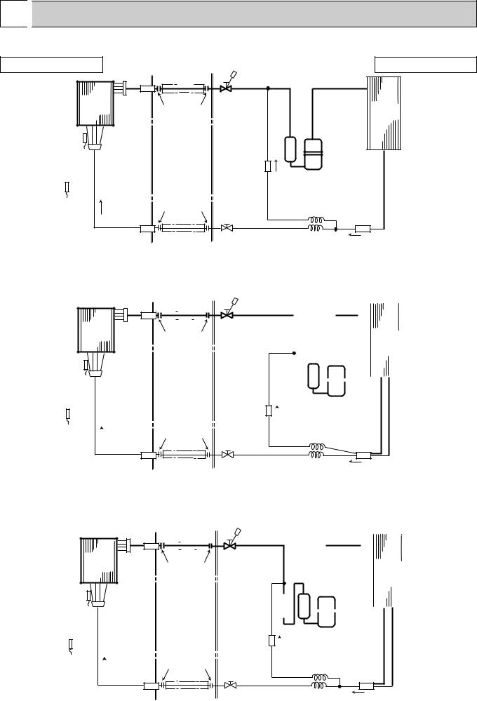
 REFRIGERANT SYSTEM DIAGRAM
SE-1.6AR.TH |
|
|
SU-1.6NR.TH |
INDOOR UNIT |
|
Refrigerant pipe [12.7 |
OUTDOOR UNIT |
|
|
(Option) |
|
|
|
(with heat insulator) |
|
Indoor |
Strainer |
Stop valve |
Outdoor |
heat |
|
(with service port) |
|
exchanger |
|
Flared connection |
heat |
|
|
|
exchanger |
Indoor coil thermistor
Distributor |
|
|
(With strainer) |
Dis pressure |
|
|
regulator |
Compressor |
|
|
Room temperature |
Flared connection |
Capillary tube |
|
thermistor |
|||
|
([3.0x[1.8xR100) |
||
|
|
Strainer
Strainer |
Refrigerant pipe |
Stop valve |
Capillary tube |
|
|
(Option) |
[6.35 |
|
([3.0x[1.8xR550) |
|
|
|
||
(with heat insulator)
SE-2AR.TH |
|
|
|
|
|
|
|
|
|
|
|
|
|
|
|
|
|
|
|
|
|
|
|
|
|
|
|
|
|
|
|
SU-2NR.TH |
|||
|
|
|
|
|
|
|
|
|
|
|
|
|
|
|
|
|
|
|
|
|
|||||||||||||||
INDOOR UNIT |
|
|
|
Refrigerant pipe [15.88 |
|
|
|
|
|
|
|
|
|
|
|
|
|
|
|
OUTDOOR UNIT |
|||||||||||||||
|
|
|
|
|
|
(Option) |
|
|
|
|
|
|
|
|
|
|
|
|
|
|
|
|
|
|
|
|
|
|
|||||||
|
|
|
|
|
|
|
|
|
|
|
|
|
|
|
|
|
|
|
|
|
|
|
|
|
|
|
|
||||||||
|
|
|
|
|
|
(with heat insulator) |
|
|
|
|
|
|
|
|
|
|
|
|
|
|
|
|
|
|
|
|
|
|
|||||||
|
|
|
|
|
|
|
|
|
|
|
|
|
Stop valve |
|
|
|
|
|
|
|
|
|
|
|
|
|
|
|
|
|
|
|
|
|
|
|
|
|
|
|
|
|
|
|
|
|
|
|
|
|
|
|
|
|
|
|
|
|
|
|
|
|
|
|
|
|
|
|
|
|
|
Indoor |
Strainer |
|
|
|
|
|
|
|
|
|
|
|
|
|
|
|
|
|
|
|
|
|
Outdoor |
|
|||||||||||
heat |
|
|
|
|
|
|
|
|
|
(with service port) |
|
|
|
|
|
|
|
|
|
|
|
|
|
|
|
||||||||||
exchanger |
|
|
|
Flared connection |
|
|
|
|
|
|
|
|
|
|
|
|
|
|
heat |
|
|||||||||||||||
|
|
|
|
|
|
|
|
|
|
|
|
|
|
|
|
|
|
|
|
|
|
|
|
|
|
|
|
exchanger |
|
||||||
Indoor coil |
|
|
|
|
|
|
|
|
|
|
|
|
|
|
|
|
|
|
|
|
|
|
|
|
|
|
|
|
|
|
|
|
|||
|
|
|
|
|
|
|
|
|
|
|
|
|
|
|
|
|
|
|
|
|
|
|
|
|
|
|
|
|
|
|
|
||||
thermistor |
|
|
|
|
|
|
|
|
|
|
|
|
|
|
|
|
|
|
|
|
|
|
|
|
|
|
|
|
|
|
|
|
|||
Distributor |
|
|
|
|
|
|
|
|
|
|
|
|
|
|
|
|
|
|
|
|
|
|
|
|
|
|
|
|
|
|
|||||
|
|
|
|
|
|
|
|
|
|
|
|
|
|
|
|
|
|
|
|
|
|
|
|
|
|
|
|
|
|
||||||
|
|
|
|
|
|
|
|
|
|
|
|
|
|
|
|
|
|
|
|
|
|
|
|
|
|
|
|
|
|
||||||
(With strainer) |
|
|
|
|
|
|
|
|
|
|
|
|
|
|
|
|
|
|
|
|
|
|
|
|
|
|
|
|
|
|
|||||
|
|
|
|
|
|
|
|
|
|
|
|
|
|
|
|
|
|
|
|
|
|
|
|
|
|
|
|
|
|
||||||
|
|
|
|
|
|
|
|
|
|
|
|
|
|
|
|
|
|
|
|
|
|
|
|
|
|
|
|
|
|
|
|
|
|
|
|
|
|
|
|
|
|
|
|
|
|
|
|
|
|
|
Accumulator |
|
Compressor |
||||||||||||||||||
|
|
|
|
|
|
|
|
|
|
|
|
|
Dis pressure |
|
|
|
|
|
|
|
|
|
|||||||||||||
|
|
|
|
|
|
|
|
|
|
|
|
|
|
|
|
|
|
|
|
|
|
|
|
|
|
|
|
|
|
|
|
|
|
|
|
Room temperature |
|
|
|
|
|
|
|
|
|
|
|
|
regulator |
|
|
|
Capillary tube |
||||||||||||||||||
|
|
|
|
|
|
Flared connection |
|
|
|
||||||||||||||||||||||||||
|
|
|
|
|
|
|
|||||||||||||||||||||||||||||
thermistor |
|
|
|
|
|
|
|
|
|
||||||||||||||||||||||||||
|
|
|
|
|
|
|
|
|
|
|
|
|
|
|
|
([3.0x[2.0xr100) |
|||||||||||||||||||
|
|
|
|
|
|
|
|
|
|
|
|
|
|
|
|
|
|||||||||||||||||||
Strainer
Strainer |
Refrigerant pipe |
Stop valve |
Capillary tube |
|
|
(Option) |
[6.35 |
|
([3.0x[2.0xr700) |
|
|
|
||
(with heat insulator)
SE-2.5AR.TH |
|
|
|
|
|
|
|
|
|
|
|
|
|
|
|
|
|
|
|
|
|
|
|
|
|
|
|
|
SU-2.5NR.TH |
||||
|
|
|
|
|
|
|
|
|
|
|
|
|
|
|
|
|
|
|
|
|
|
|
|
|
|
|
|
|
|
|
|
|
|
|
INDOOR UNIT |
|
|
Refrigerant pipe [15.88 |
|
|
|
OUTDOOR UNIT |
|||||||||||||||||||||||||
|
|
|
|
|
|
|
|
|
|
|
|
|
|
|
|
||||||||||||||||||
|
|
|
|
|
|
|
|
|
|
|
|
|
|
|
|||||||||||||||||||
|
|
|
|
|
|
(Option) |
|
|
|
|
|
|
|
|
|
|
|
|
|
|
|
|
|
|
|
||||||||
|
|
|
|
|
|
(with heat insulator) |
Stop valve |
|
|
|
|
|
|
|
|
|
|
|
|
||||||||||||||
|
|
|
|
|
|
|
|
|
|
|
|
|
|
|
|
|
|
|
|
|
|
|
|
|
|
|
|||||||
|
|
|
|
|
|
|
|
|
|
|
|
|
|
|
|
|
|
|
|
|
|
|
|
|
|
|
|||||||
|
|
|
|
|
|
|
|
|
|
|
|
|
|
|
|
|
|
|
|
|
|
|
|
|
|
|
|||||||
|
Indoor |
Strainer |
|
|
|
|
|
|
|
|
|
Outdoor |
|
||||||||||||||||||||
|
heat |
|
|
Flared connection |
(with service port) |
|
|
|
|
||||||||||||||||||||||||
|
exchanger |
|
|
|
|
|
|
|
|
|
|
|
|
|
heat |
|
|||||||||||||||||
|
|
|
|
|
|
|
|
|
|
|
|
|
|
|
|
|
|
|
|
|
|
|
|
|
|
exchanger |
|
||||||
|
Indoor coil |
|
|
|
|
|
|
|
|
|
|
|
|
|
|
|
|
|
|
|
|
|
|
|
|
|
|
|
|
|
|||
|
|
|
|
|
|
|
|
|
|
|
|
|
|
|
|
|
|
|
|
|
|
|
|
|
|
|
|
|
|
||||
|
thermistor |
|
|
|
|
|
|
|
|
|
|
|
|
|
|
|
|
|
|
|
|
|
|
|
|
|
|
|
|
|
|||
|
Distributor |
|
|
|
|
|
|
|
|
|
|
|
|
|
|
|
|
|
|
|
|||||||||||||
|
|
|
|
|
|
|
|
|
|
|
|
|
|
|
|
|
|
|
|
||||||||||||||
|
|
|
|
|
|
|
|
|
|
|
|
|
|
|
|
|
|
|
|
||||||||||||||
|
(With strainer) |
|
|
|
|
|
|
|
|
|
|
|
|
|
|
|
|
|
|
|
|||||||||||||
|
Dis pressure |
Accumulator |
Compressor |
||||||||||||||||||||||||||||||
|
|
|
|
|
|
|
|
|
|
|
|
|
|
|
|||||||||||||||||||
|
|
|
|
|
|
|
|
|
|
|
|
|
|
|
|
|
|
|
|
|
|
|
|
|
|
|
|
|
|||||
|
|
|
|
|
|
|
|
|
|
|
|
|
|
|
|
|
|
|
|
|
|
|
|
|
|
|
|
||||||
|
Room temperature |
|
|
|
|
|
Flared connection |
regulator |
|
|
|
Capillary tube |
|
|
|
|
|
|
|
|
|
|
|||||||||||
|
|
|
|
|
|
|
|
|
|
|
|
|
|
|
|
|
|
|
|||||||||||||||
|
|
|
|
|
|
|
|
|
|
|
|
|
|
|
|
|
|
||||||||||||||||
|
thermistor |
|
|
|
|
|
|
|
|
|
|
|
|
|
|
|
|
|
|
|
|||||||||||||
|
|
|
|
|
|
|
|
|
|
|
|
|
|
|
|
|
([3.0x[2.0xR100) |
||||||||||||||||
|
|
|
|
|
|
|
|
|
|
|
|
|
|
|
|
|
|
|
|||||||||||||||
Strainer
Strainer |
Refrigerant pipe |
Stop valve |
Capillary tube |
|
|
(Option) |
[9.52 |
|
([3.0x[2.0xR600) |
|
|
|
||
(with heat insulator)
12
 Loading...