


Users manual: Mitsubishi Delica SpaceGear
Dr D John Pons 1
The following data have been collected from various sources, including verbal discussions and opinions of others. The author makes no claim for the accuracy of the data nor accepts any liability in connection with their use. Most of the data are for the
1997 2.8 turbo diesel model.
This manual may be freely reproduced.
1 Contact me at rhino@pons.ws to provide feedback, corrections, and any additional information. Edition E12 December 2005
Credit: http://www.mitsubishi-motors.co.jp/NEWS/recall/h150701/10960.html
1
0 Vehicle details
Useful details when you buy spare parts
Year
Configuration
Registration number
Engine type
Engine number
Model
Chassis number
Transaxle number
Color int opt
2

1 Getting started
This is a quick driving tutorial.
1.1Driving the Delica
(1)Gearbox must be in park mode (P).
(2)Turn ignition key until instrument lights are illuminated (see Figure 1).
(3)Wait until glow plug light (see Figure 1) is extinguished. This usually happens very fast, or even instantly if the engine is already warm.
(4a) Turn the key further to swing the engine - release when successful.
(4b) If engine struggles to start2, then turn off ignition, switch on again immediately, wait for glow plug light to go off, wait a further 5 seconds or so until a click is heard from the engine, and then turn the engine [1].
(5)Footbrake must be applied before 'drive' can be engaged.
(6)Ensure drive is in appropriate range. Usually two wheel drive (2H) is fine for town driving. Use ‘Super Select’ gear shift (on floor, see description below) to change as necessary.
(7)Use column mounted gear shift to select reverse (R) or drive (D) as appropriate.
(8)After driving, key can only be removed from ignition if automatic transmission is in park (P).
1.2Driving a diesel engine
Driving a diesel engine is much the same as a petrol engine. Except that the acceleration is generally slower3, and the torque at low engine revolutions (revs) is lower. Therefore it is generally better to keep the revs slightly higher than in a petrol engine vehicle, especially if climbing hills. Diesel engines have better thermodynamic efficiency under part load than petrol engines4.
2For engines that are hard to start or emit copious smoke, there can be several causes and solutions. These include replace batteries (both), clean or replace straps to glow plugs, replace glow plugs, replace or service fuel pump. Search http://www.delicaclub.com and http://www.pocuk.com/ for more clues.
3Diesels tend not to accelerate much more when the pedal is floored. A tip that might be useful: "A diesel however won't go much faster and any foot planting results in unburnt fuel going out the tail pipe. When you get to that point where it won't go any faster try taking your foot off slightly and you will find you won't go any slower and save a heap of fuel" [11].
4The superior efficiency of a diesel compared to petrol engine is due to the different thermodynamic cycle. Petrol engines throttle the air intake to reduce power, and this is inefficient compared to the diesel method of injecting less fuel.
3
2Instruments and gears
This section describes the main driver controls.
2.1Instrument panel Delica 1997
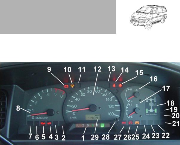
Figure 1 Instrument panel
See Figure 1 for the layout.
1Gearbox: Shows gear position for automatic gearbox. Also an ‘O/D off’ indicator if overdrive has been deselected by the driver.
2‘HOLD’ - usually off. If on, it shows driver has used the A/T switch to force the gearbox to try to start in second rather than first gear (useful on ice or mud to reduce slip).
3‘PWR’ - usually off. If on, it shows driver has used the A/T switch to force the gearbox to a 'power' mode: faster acceleration by going to higher revs before changing up a gear.
4‘A/T’ warning - usually off. Indicates over-temperature in gearbox if it comes on while driving. Stop and idle for 5 minutes in park. Check ATF fluid level with engine on and in neutral. Consider switching overdrive OFF.
5Oil pressure warning - usually off. Indicates loss of engine oil pressure if it comes on while driving - may cause major engine damage if driven in this condition. Check oil level in engine.
4
6<unknown>
7Glow plug status (coil symbol)- usually on momentarily when ignition is energised. Wait for this light to extinguish before turning the engine.
8Engine revolutions per minute (revs). The information is of no real value if you have an automatic gearbox and mainly use drive (D). But if you are heavily laden, then it’s useful to check that the revs are not too low - low revs under high load will generate more heat in the gearbox.
9Battery charge warning - usually off when driving. If on (which it should be at start-up), it shows that the battery is not being charged. If it comes on while driving it means there is an electrical fault, in battery, alternator, or alternator drive belt (the belt could be broken or simply slipping). You might be able to continue driving for some time especially if you can limit the amount of electrical load.
10Fuel filter warning - usually off. If on, there is water that needs to be drained from the base of the fuel filter.
11High beam (brights)
12Speed
13<unknown>
14Seat belt status - strap yourself in.
15Door warning - lights up if a door is open when the ignition is on.
16Temperature gauge - should be well below the ‘hot’ mark.
17Fuel gauge.
184WD transmission status - shows what the driver has selected with the 4WD selector. See Figure 2 for detail.
19-20 <unknown>
21 Low fuel indicator (lights when the tank is down to about 9 litres [ref 13]).
22-24 <unknown>
25Anti-skid braking (ABS) - usually off. Performs self-test of ABS system when ignition is turned on, and then light goes off.
26Brake status - lights up if handbrake is on. Might also light up when brake fluid is low or pads are worn?
27Supplementary restraint system (SRS) - usually off. This is the air bag
5
system. The light should come on for a few minutes when the ignition is turned on - this shows that the self-test is being done. When the test is completed successfully then the light is extinguished. If the light stays on then it is a warning that the air-bag will not work.
28Button for odometer - one push toggles the display (29) between odometer and trip distance. A sustained push will reset the trip distance to zero.
29Odometer display. Only on when ignition is on.
2.2Selecting the right gear
2.2.1 |
Gear shift |
The automatic gearshift is mounted on the steering column. The side of the steering column shows the stepped gear pattern. Note that it is basically a valley with N at the lowest point (furthest away from the driver).
Lift the gear directly towards your chest to move it out of park (P). Thereafter it is away from your chest until it gets to neutral (N). From N to low gear (L) the gear lever needs to again be lifted towards your chest.
2.2.2 |
Overdrive selection |
Overdrive (O/D) is activated/ deactivated by a button at the end of the automatic gearshift. When deactivated then the 'O/D Off' light illuminates (see Figure 1: 1).
Overdrive ON can safely be used for town driving and a lightly loaded vehicle. Overdrive ON permits the automatic transmission control logic to make use of (1) an overdrive clutch and (2) a lock on the torque converter [3]. Consequentially with overdrive on the driver will feel several small gear changes between the three main gears. With overdrive ON the vehicle effectively has another top gear.
Switch overdrive OFF if you need slower speeds with greater torque, e.g. heavily loaded or difficult terrain. With overdrive OFF the gearbox controller is limited to using only the three main gears. If the vehicles is repeatedly making multiple small gear changes when under load, then move overdrive to OFF until conditions change. This will make the vehicle easier to drive. This also has the important benefit of reducing heat generation in the gearbox. Over temperature of gearbox will activate the A/T warning light. (Stop and idle for 5 minutes in park.)
2.2.3 |
4WD transmission selection |
The driver has to manually engage and disengage four wheel drive (4WD) using the "Super Select" selection lever. This is typical of a full 4WD vehicle, and gives the
Delica full 4WD capability (the same capability as the Mitsubishi Pajero for
6
example). By comparison some other vehicles (e.g. Mitsubishi RVR SportsGear) have permanently engaged 4WD over which the driver has no control.
For driving in town and on sealed roads (bitumen or concrete), two wheel drive is adequate.
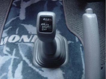
The 4WD selection lever is floor mounted, see Figure 2.
2H Two wheel drive in high range: Rear wheel drive - suitable for driving in conditions where a normal car could go. Ideal for town driving.
4H Four wheel drive in high range: Front and rear wheels drive (4WD) - suitable for slippery or rough or steep conditions - wherever you need better traction or steering.
“H” is for high range. You Figure 2: 4WD transmission selection. can safely use 4H for
normal driving conditions including bitumen and
concrete roads. But front tyre wear may be heavier than in 2H.
Driver may shift from 2H to 4H and back while driving, but take your foot off the accelerator pedal when you do, and preferably try to be steering straight ahead (to minimise gear engagement forces).
Transmission may not immediately shift when commanded, but will wait until the torque permits the change - dashboard lights Fig 1: 18 will flash during this period.
4HLc Four wheel drive in high range with locked central differential: For extra traction in low-grip terrain. This is the same as 4H, with the addition that the transfer case (central differential) is locked. With standard 4H there is still the possibility of slipping since all the power could go to one of the axles only. With 4HLc this possibility is prevented: both the front and the rear axle will get torque. Can this gear be engaged and disengaged while driving? Yes, it should be possible [3] (some disagree [6]), but only engage on slippery surface, don’t accelerate, and try to be steering straight.
Warning: Use locked centre differential only when surfaces are slippery or have a lot of give for the tyres. Do not use on hard surfaces for extended time as the transmission or tyres may be damaged.
4LLc Four wheel drive in low range with locked central differential: Same as 4HLc,
7

but with a lower gear range. Vehicle will be slower, but will have increased torque on wheels. Stop completely before engaging or disengaging this gear. Same warning applies as for 4HLc, i.e don’t use on high-grip surfaces.
The low range ‘L’ always has locked central differential ‘Lc’. You can’t have low range on its own with the Mitsubishi design.
2.3Additional controls
2.3.1 |
Door controls |
Controls located on the driver’s door are shown in Figure 3.
1Switch to select left or right external mirror.
2Switch to fold both mirrors in/out. Note, if a mirror gets shoved in, do not force it out again manually. Instead, use the motor drive to bring it fully in, and then motor drive it out again.
3Joystick pad to adjust mirror as selected by (1).
4Door lock - locks/unlocks all doors.
5Window lock - locks/unlocks all electrically driven windows.
6Driver side window control.
7Passenger side window control.
Figure 3: Door controls
2.3.2Sub-steering wheel controls
The controls under the steering wheel are shown in Figure 4.
1Idle adjustment.
2Bonnet catch - pull to release bonnet (engine hood).
3Turbo timer - after market device, used to keep engine running for a few minutes after
power down. This is supposed to cool the turbocharger. Hard to see why this would be necessary in town driving but maybe it has value for hard driving. Mitsubishi
designers have not included it as a standard feature.
4Fuel tank catch - pull to release. The filler cap is between the front passenger and sliding door.
5Steering wheel angle adjustment - permits wheel to be adjusted for different
8
driver height.
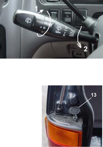
2.3.3Windscreen wiper controls
The controls are shown in
Figure 5.
1Rear wiper - twist anticlockwise to activate. Water squirt at the end of the range in both directions. Water fill bottle is at left rear of vehicle, see Figure 6.
2Front wipers - rotate
downwards to
activate intermittent, Figure 5: Windscreen wiper controls then normal wiper
speed, then fast wipers.
Pull whole lever towards driver to spray water on front windscreen. Front water fill bottle is under the front bonnet. The rear water bottle is at the back left - open the rear hatch and find it as shown in Figure 6.
Figure 6: Fill location for rear windscreen water spray.
9

3Solving simple problems
3.1Changing a wheel
The spare wheel is underneath at the rear.
The tools are inside at the rear right, see Figure 7.
Remove the tools and use them to unscrew the bolt next to the rear door latch, see Figure 8. The bolt will need to be turned anti-clockwise for many turns, and it may be stiff.
Figure 7: Jack and tools for changing tyre. Extra socket for 12 V power also visible (round black cap) - takes cigarette lighter type fitting.
Figure 8: Lowering the spare wheel. Use the socket spanner to turn the bolt head anti-clockwise.
10
Once the bolt has been unscrewed sufficiently, it lowers the cage holding the spare wheel. The spare wheel can now be removed, see Figure 9.
Remove the plastic wheel cap (if fitted) with the tool provided, or a flat screwdriver, see
Figure 10.
Before you jack up the flat wheel, loosen all the screws by a small amount, see Figure 11. The screws may be very tight.
Loosening them on the ground is necessary because the wheel will turn if you try to do this when it is raised.
You don’t want the van moving and falling off the jack, so make sure the hand brake is on. If the ground slopes, then put rocks or bricks in front of and behind some of the good wheels. Now use the jack to raise the vehicle. Raise it until the tyre easily clears the ground. Then remove all the wheel screws completely, and take off the flat wheel.
If possible, put some oil or grease on the screw threads and where the head faces the rim. This ensures that your tightening efforts will go into clamping the wheel onto the van, not just overcoming friction. Screws that squeal, or need the spanner the whole way, have too much friction and might be ineffective. Obviously it is sometimes impractical to lubricate the screws if you are changing the wheel at the roadside.
Figure 9: Releasing the spare wheel.
Slide it out backwards.
Figure 10: Remove plastic wheel cap, by prising with flat bar or screwdriver.
Figure 11: Undoing screws on wheel.
Turn anti-clockwise to loosen, i.e. push down from this position.
Offer up the spare wheel to the hub. The wheel is heavy so be careful with your back. The best position is to sit on the ground facing the wheel, with your feet on each side of the tyre. Then you can use your feet to raise the tyre to its position, and
11

you still have your hands free to insert the screws. If the wheel will not go on properly, check that the vehicle has been raised enough. Tighten the screws as far as you can. Turn them clockwise. You don’t want the wheel to be on skew, so tighten each screw a little in turn: don’t concentrate all your effort on one screw.
Then lower the jack and remove it. Tighten all the wheel screws as tight as you can. You can exert more force pulling the spanner up than pushing it down, so arrange your position accordingly.
3.2Roof racks
The vehicle will accept roof racks, but special types are required because of the high roof, and the non-structural trim attached to the gutter.
The following products are candidates (prices at 2004):
(1)Thule roof rack kit 426. This has a special foot with (a) a long tongue and (b) a special shape to the claw. It attaches to the gutter. Part (426) is unique to the Delica, and only for high-top models from 1996 onwards. (A similar part, 425, is for a low top Delica). Available in NZ from Hampco for NZ$430 for a set (4 feet plus two bars). In Australia the price is AU$250.
(2)Prorack pad mount rack SB1000. This is permanently rivetted to the roof5. Available in NZ ex Repco for $230. Fitting by a panel beater is additional.
(3)Prorack track system. This has a pair of long tracks (ST14) which are permanently attached to the roof, and then racks (SB3000) which slide into to the track. Available in NZ ex Repco for $160 and $389 respectively. Fitting is extra.
(4)Second hand car dealers may sometimes have racks that they have removed at the time of import. Pajero racks can be modified to fit.
The Delica is already a high vehicle, and adding roof racks may mean that it no longer fits into the garage! You could extend the radio aerial (at front right, high up) as a reminder not to drive into low spaces.
5One wonders how much load this type of design can take, since the stresses go into the flat roof rather than the gutter.
12
3.3Tow-bar
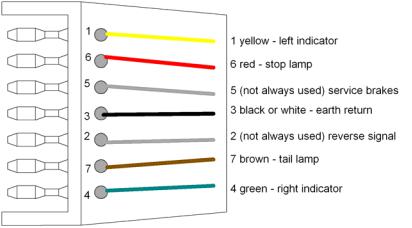
Tow bars are readily available for the Delica. However, the factory rear chrome bars usually have to be taken off. The standard electrical wiring in
Australia and New Zealand is a 7-pin flat plug. The wiring of the pins is shown in Figure 12.
Figure 12: Wiring for trailer 7-pin flat plug.
3.4Jump starting
The following excellent description was provided by Exide [27] on starting the engine when the battery is flat. The text applies to vehicles in general.
(1)“STEP 1- WARNING! Jump starting can damage the vehicle electronics.
Check the vehicle operating manual. If there are no specific instructions then follow the steps below. If the failed battery is open circuit* do not attempt to jump-start.
*Open circuit batteries can be detected by:
a)battery volts reading zero immediately a high rate discharge test is applied.
b)when the battery will not accept charge current.
(2)STEP 2 - Make sure both vehicle ignitions are switched OFF and all electrical equipment is OFF.
(3)STEP 3 - Connect the vehicles in the following EXACT sequence and make sure the jumper leads are clear of any moving parts.
a)Take the RED jumper lead and connect to the POSITIVE terminal (marked “+” or POS) of the discharged battery.
b)Connect the other end of the RED jumper lead to the positive terminal of the charged battery.
c)Take the BLACK jumper lead and connect one end to the NEGATIVE terminal (marked “-“ or NEG) of the charged battery.
d)Make the final connection to the engine block or chassis of the stalled vehicle. (Negative earth vehicles only).
(4)STEP 4 - After starting the vehicle with the discharged battery, allow the engine to run at idle for five minutes before disconnecting the jumper leads.
This allows the electrical systems of both cars to balance.
(5)STEP 5- Remove the BLACK cable first from the vehicle with the discharged battery then the opposite end from the charged battery. Repeat for the RED cable.” [27]
13

4 Engine
compartment
The overall view of the engine bay6 is shown in Figure 13-16.
Not shown is the oil filter, which is underneath at front right.
Figure 13: Overall view of engine bay. See following figures for details.
1 Fuse box.
2 Brake fluid reservoir and fill cap.
3 Air cleaner.
4 Dipstick for engine oil (partly hidden by hose).
5 Oil fill cap for engine. Fill engine oil here.
6 Dipstick for
Figure 14: Right side of engine bay. automatic transmission (AT).
Fill ATF slowly down this pipe.
6The Delica is unusual in having the engine at the front, whereas other coaches (e.g. Toyota) tend to have it under the driver seat. The Delica layout is a consequence of the design philosophy that adopts the Pajero layout. As a result, the bonnet for the Delica engine bay is short, and the firewall wraps around the engine.
14

7Hose and clamp for compressed air flowing from turbo-charger7, through intercooler, and into engine.
8Intercooler - cools down hot air ex turbo-charger.
9Fill cap for power steering.
10Battery terminal.
There are two batteries in
parallel in this model. Other models may have only a single battery.
11Reservoir and fill cap for radiator. Use anti-freeze and water.
12Fill cap for front windscreen washer water.
7A turbo-charger ('turbo') increases the power of an engine by forcing more air into it. This means more fuel can be burned (because of the increased oxygen) and hence more power produced. A turbo charger does work compressing air and needs energy. It gets this from the hot and slightly pressurised exhaust gases which spin an internal part called a turbine. The turbine drives the compressor (fan). The other way of increasing the power of a given engine size is a super-charger, which is a shaft driven compressor. A turbo-charger is more efficient than a supercharger, but not as responsive at low engine speeds.
15
 Loading...