


SPLIT-TYPE, HEAT PUMP AIR CONDITIONERS
July 2007
No. OC320
REVISED EDITION-B
TECHNICAL & SERVICE MANUAL
|
|
|
|
|
|
|
|
|
|
|
|
|
|
|
Indoor unit |
|
|
|
|
[Model names] |
[Service Ref.] |
|||
SLZ-KA25VA |
SLZ-KA25VA.TH |
|||
|
SLZ-KA25VA1.TH |
|||
SLZ-KA35VA |
SLZ-KA35VA.TH |
|||
|
SLZ-KA35VA1.TH |
|||
SLZ-KA50VA |
SLZ-KA50VA.TH |
|||
|
SLZ-KA50VA1.TH |
|||
SLZ-KA25VAL |
SLZ-KA25VAL.TH |
|||
|
SLZ-KA25VAL1.TH |
|||
SLZ-KA35VAL |
SLZ-KA35VAL.TH |
|||
|
SLZ-KA35VAL1.TH |
|||
SLZ-KA50VAL |
SLZ-KA50VAL.TH |
|||
|
SLZ-KA50VAL1.TH |
|||
Revision:
•SLZ-KA25/35/50VA(L)1.TH are added in REVISED EDITION-B.
•Some descriptions have been modified.
•Please void OC320 REVISED EDITION-A.
Note:
•This manual describes only service data of the indoor units. When servicing out-
door units, please refer to the service manual No.OC322 or OC323 together with this manual.
•RoHS compliant products have <G> mark on the spec name plate.
•For servicing RoHS compliant products, refer to the RoHS Parts List.
|
|
|
CONTENTS |
|
|
|
1. TECHNICAL CHANGES ·········· |
|
|
|
2. PART NAMES AND FUNCTIONS ······ |
|
|
|
3. SPECIFICATIONS············· |
|
|
|
4. OUTLINES AND DIMENSIONS ······· |
Model name |
|
5. WIRING DIAGRAM ············ |
|
|
6. REFRIGERANT SYSTEM DIAGRAM······ |
||
indication |
|
INDOOR UNIT |
|
|
7. TROUBLESHOOTING ··········· |
||
|
|
|
|
|
|
|
8. 4-WAY AIR FLOW SYSTEM ········ |
|
|
|
9. DISASSEMBLY PROCEDURE ······· |
ON/OFF |
TOO TOO |
|
10. PARTS LIST ··············· |
WARM COOL |
|
||
|
|
|
|
FAN SELECT
AUTO COOL |
TEMP. ON/OFF |
11. RoHS PARTS LIST ············ |
|
||
HEAT DRY VANE TIME |
|
|
MODE |
|
|
RESET |
|
|
SLZ-KA25,35,50VAL.TH SLZ-KA25,35,50VA.TH
SLZ-KA25,35,50VAL1.TH SLZ-KA25,35,50VA1.TH
REMOTE CONTROLLER

1 
 TECHNICAL CHANGES
SLZ-KA25VAL.TH SLZ-KA25VAL1.TH SLZ-KA35VAL.TH SLZ-KA35VAL1.TH SLZ-KA50VAL.TH SLZ-KA50VAL1.TH SLZ-KA25VA.TH SLZ-KA25VA1.TH SLZ-KA35VA.TH SLZ-KA35VA1.TH SLZ-KA50VA.TH SLZ-KA50VA1.TH
• PANEL has been changed.
SLP-2AL |
|
SLP-2ALW |
SLP-2AA |
|
SLP-2AAW |
(White : 0.70Y 8.59/0.97) |
|
(Pure white : 6.4Y 8.9/0.4) |
2
2 
 PART NAMES AND FUNCTIONS
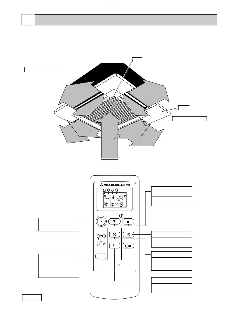
Indoor Unit
SLZ-KA25VAL.TH SLZ-KA25VA.TH SLZ-KA35VAL.TH SLZ-KA35VA.TH SLZ-KA50VAL.TH SLZ-KA50VA.TH
SLZ-KA25VAL1.TH SLZ-KA35VAL1.TH SLZ-KA50VAL1.TH
SLZ-KA25VA1.TH SLZ-KA35VA1.TH SLZ-KA50VA1.TH
Horizontal Air Outlet
Sets horizontal airflow automatically during cooling or dehumidifying.
Filter
Removes dust and pollutants from inhaled air.
Grille
Auto Air Swing Vane
Disperses airflow up and down and adjusts the angle of airflow direction.
Air Intake
Inhales air from room.
Wireless remote comtroller |
|
SLZ-KA25VAL.TH |
|
SLZ-KA35VAL.TH |
|
SLZ-KA50VAL.TH |
|
SLZ-KA25VAL1.TH |
|
SLZ-KA35VAL1.TH |
h |
SLZ-KA50VAL1.TH |
|
ON / OFF button
To start and to stop operation.
MODE SELECT button
To change the operation mode; Auto, Cooling , Heating and Drying . (SLZ)
ON/OFF TOO  TOO WARM
  COOL
COOL
FAN SELECT
AUTO COOL
HEAT DRY VANE TIME
MODE
RESET
Attention:
TEMPERATURE
SETTING button
To set any desired room temperature.
TIMER SELECT button
To set time to start or stop unit operation.
FAN SPEED button
To set fan speed to Low, Medium or High.
VANE CONTROL button
To change the airflow direction.
• Avoid pushing buttons with fingernails and other sharp objects. Sharp objects may damage remote controller.
3
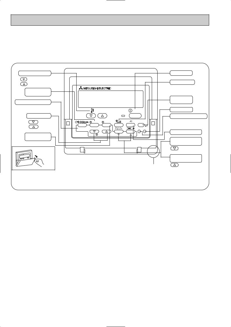
● Wired remote controller
Once the controllers are set, the same operation mode can be repeated by simply pressing the ON/OFF button.
SLZ-KA25VA.TH SLZ-KA35VA.TH SLZ-KA50VA.TH
SLZ-KA25VA1.TH SLZ-KA35VA1.TH SLZ-KA50VA1.TH
Temperature setting buttons |
|
|
|
Down |
|
|
|
Up |
|
|
|
Timer Menu button |
|
|
|
(Monitor/Set button) |
|
|
|
Mode button (Return button) |
|
|
|
|
|
TEMP. |
|
Set Time buttons |
|
|
|
Back |
|
MENU |
ON/OFF |
Ahead |
BACK |
MONITOR/SET |
DAY |
|
|||
Timer On/Off button |
PAR-21MAA |
CLOCK |
|
(Set Day button) |
|
|
|
Opening the |
|
|
|
lid |
|
|
|
|
ON/OFF |
|
|
FILTER |
|
|
CHECK |
TEST |
OPERATION |
CLEAR |
|
Built-in temperature sensor
ON/OFF button
Fan Speed button
Filter  button (<Enter> button)
Test Run button
Check button (Clear button)
Airflow Up/Down button
Louver button
( Operation button)
To return operation number
Ventilation button
( Operation button)
To go to next operation number
4
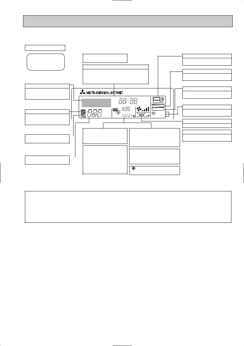
● Wired remote controller
Display Section
For purposes of this explanation, |
Day-of-Week |
all parts of the display are shown |
Shows the current day of the week. |
as lit. During actual operation, only |
|
the relevant items will be lit. |
Time/Timer Display |
Shows the current time, unless the simple or Auto Off timer is set.
If the simple or Auto Off timer is set, the time to be switched off is shown.
Identifies the current operation
Shows the operating mode, etc. *Multilanguage display is available.
|
TIME SUN MON TUE WED THU FRI SAT |
||
|
TIMER |
Hr |
ON |
|
AFTER |
AFTER |
OFF |
|
ERROR CODE |
|
FUNCTION |
|
˚F˚C |
|
FILTER |
“Centrally Controlled” indicator |
˚F˚C |
|
|
|
WEEKLY |
||
Indicates that operation from the |
ONLY1Hr. |
|
SIMPLE |
|
AUTO OFF |
||
remote controller has been prohib- |
|
|
|
ited by a master controller.
|
|
|
|
|
Up/Down Air Direction indica- |
|
Room Temperature display |
“Timer is Off” indicator |
|
|
|
|
tor |
|
Shows the room temperature. The room |
|
|
|
|
Shows the direction of the |
|
temperature display range is 8~39:. |
|
Indicates that the timer is off. |
|
|
|
|
outcoming airflow. |
|
The display blinks if the temperature |
|
|
|
|
|
“One Hour Only” indicator |
|
is less than 8: or 39: or more. |
|
|
|
|
|
|
Louver display |
|
|
|
|
|
|
Displayed if the airflow is set to |
|
|
Temperature Setting |
|
|
|
|
low or downward during COOL |
|
Indicates the action of the swing louver. |
|
|
|
|
or DRY mode. (Operation varies |
|
Does not appear if the louver is not |
|
Shows the target temperature. |
|
|
|
|
according to model.) |
|
running. |
|
|
|
|
|
The indicator goes off in one hour, |
|
(Power On indicator) |
|
|
|
|
|
when the airflow direction also |
|
|
|
|
|
|
|
changes. |
|
Indicates that the power is on. |
“Sensor” indication
Displayed when the remote controller sensor is used.
“Locked” indicator
Indicates that remote controller buttons have been locked.
“Clean The Filter” indicator
To be displayed on when it is time to clean the filter.
Timer indicators
The indicator comes on if the corresponding timer is set.
Fan Speed indicator
Shows the selected fan speed.
Ventilation indicator
Appears when the unit is running in Ventilation mode.
Note:
●“PLEASE WAIT” message
This message is displayed for approximately 3 minutes when power is supplied to the indoor unit or when the unit is recovering from a power failure.
●“NOT AVAILABLE” message
This message is displayed if an invalid button is pressed (to operate a function that the indoor unit does not have).
If a single remote controller is used to operate multiple indoor units simultaneously that are different types, this message will not be displayed as far as any of the indoor units is equipped with the function.
5
3 
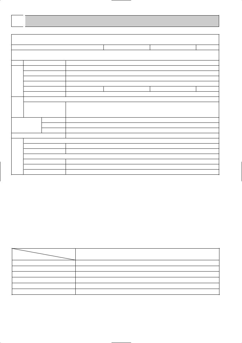
 SPECIFICATIONS
Indoor service ref.
Function
Power supply
Capacity Air flow (High/Medium/Low)
|
|
Power outlet |
||
Electrical |
data |
Running current 1 |
||
Power input |
Rated frequency |
|||
|
|
|||
|
|
Dew prevention heater |
||
|
|
Power factor 1 |
||
|
|
Fan motor current 1 |
||
Fan |
motor |
Model |
|
|
Winding |
|
|||
|
|
|
||
|
|
resistance (at 26:) |
||
|
|
|
Width |
|
Dimensions |
Height |
|||
|
|
|
Depth |
|
|
|
Weight |
|
|
|
|
Air direction |
||
|
|
Sound level(High/Medium/Low) |
||
Special |
remarks |
Fan speed(High/Medium/Low) |
||
Thermistor TH1(at25:) |
||||
|
|
Fan speed |
regulator |
|
Thermistor TH2(at25:)
Thermistor TH5(at25:)
|
SLZ-KA25VAL(1).TH |
|
SLZ-KA35VAL(1).TH |
SLZ-KA50VAL(1).TH |
||||
|
SLZ-KA25VA(1).TH |
|
SLZ-KA35VA(1).TH |
SLZ-KA50VA(1).TH |
||||
|
Cooling |
Heating |
|
Cooling |
Heating |
Cooling |
Heating |
|
|
Single phase |
|
Single phase |
Single phase |
||||
|
230V, 50Hz |
|
230V, 50Hz |
230V, 50Hz |
||||
K /h |
600/540/480 |
|
660/540/480 |
660/540/480 |
||||
A |
10 |
|
|
10 |
20 |
|||
A |
0.35 |
|
0.40 |
0.65 |
||||
W |
75 |
|
|
85 |
85 |
|||
(kW) |
0.014 |
|
0.014 |
0.014 |
||||
% |
90 |
93 |
|
94 |
94 |
97 |
97 |
|
A |
0.19 |
|
0.26 |
0.27 |
||||
|
PK6V15-LD |
|
PK6V20-LL |
PK6V20-LM |
||||
" |
WHT-BLK : 407 |
BLK-BLU : 86 |
WHT-BLK : 393 |
BLK-BLU : 164 |
WHT-BLK : 325 |
BLK-BLU : 143 |
||
BLU-YLW : 30 |
BRN-RED : 165 |
BLU-YLW : 47 |
BRN-RED : 319 |
BLU-YLW : 47 BRN-RED : 309 |
||||
|
||||||||
mm(in) |
|
|
|
|
|
|
||
|
UNIT : 570(22-7/16) |
PANEL : 650(25-9/16) |
|
|||||
mm(in) |
|
UNIT : 208(8-3/16) |
PANEL : 20(13/16) |
|
||||
mm(in) |
|
UNIT : 570(22-7/16) |
PANEL : 650(25-9/16) |
|
||||
kg |
|
UNIT : 16.5 |
|
PANEL : 3 |
|
|
||
|
4 |
|
|
|
4 |
|
4 |
|
dB(A) |
37/31/28 |
|
38/33/29 |
39/34/30 |
||||
rpm |
650/530/480 |
|
690/570/510 |
710/590/530 |
||||
|
3 |
|
|
|
3 |
|
3 |
|
k" |
10 |
|
|
10 |
10 |
|||
k" |
10 |
|
|
10 |
10 |
|||
k" |
10 |
|
|
10 |
10 |
|||
NOTE : Test conditions are based on ISO 5151.
Cooling : Indoor |
D.B. 27: W.B. 19: |
Outdoor D.B. 35: W.B. 24: |
|
Heating : Indoor |
D.B. 20: W.B. 15: |
Outdoor D.B. 7: W.B. 6: Refrigerant piping length (one way): 5m
1 Measured under rated operating frequency
Specifications and rating conditions of main electric parts
INDOOR UNIT
Item |
Service ref. |
|
|
Indoor fan capacitor |
(C1) |
Fuse |
(FUSE) |
Vane motor |
(MV) |
Terminal block |
(TB) |
Indoor fan motor thermal fuse |
|
Cord Heater |
(H2) |
SLZ-KA25VAL(1).TH SLZ-KA35VAL(1).TH SLZ-KA50VAL(1).TH
SLZ-KA25VA(1).TH SLZ-KA35VA(1).TH SLZ-KA50VA(1).TH
1.5+ 440V
250V 6.3A MSBPC20 12V 250"
TO OUTDOOR UNIT : 3P TO WIRED REMOTE CONTROLLER : 2P (SLZ-KA25/35/50VA) 141:i3:
240V AC 15W
6
(1), SLZ-KA35VA(L)(1), SLZ-KA50VA(L)(1) Service Manual")
NOISE CRITERION CURVES
SLZ-KA25VAL.TH |
|
|
|
|
<50Hz> |
|||
|
NOTCH |
SPL(dB) |
LINE |
|||||
SLZ-KA25VA.TH |
|
|
High |
37 |
|
|||
|
Medium |
31 |
|
|||||
SLZ-KA25VAL1.TH |
|
|
||||||
|
|
Low |
28 |
|
||||
SLZ-KA25VA1.TH |
|
|
|
|||||
|
|
|
|
|
||||
|
90 |
|
|
|
|
|
|
|
bar) |
80 |
|
|
|
|
|
|
|
= 0.0002 |
70 |
|
|
|
|
|
|
|
dB (0 dB |
|
|
|
|
|
|
NC-70 |
|
|
|
|
|
|
|
|
||
60 |
|
|
|
|
|
|
|
|
LEVEL, |
|
|
|
|
|
|
|
|
|
|
|
|
|
|
|
NC-60 |
|
|
|
|
|
|
|
|
|
|
PRESSURE |
50 |
|
|
|
|
|
|
|
|
|
|
|
|
|
|
NC-50 |
|
40 |
|
|
|
|
|
|
|
|
SOUND |
|
|
|
|
|
|
|
|
|
|
|
|
|
|
|
NC-40 |
|
|
|
|
|
|
|
|
|
|
BAND |
30 |
|
|
|
|
|
|
|
|
|
|
|
|
|
|
NC-30 |
|
|
|
|
|
|
|
|
|
|
OCTAVE |
20 |
APPROXIMATE |
|
|
|
|
|
|
|
TERESHOLD OF |
|
|
|
|
|
||
|
HEARING FOR |
|
|
|
|
|
NC-20 |
|
|
|
CONTINUOUS |
|
|
|
|
|
|
|
|
|
|
|
|
|
|
|
|
|
NOISE |
|
|
|
|
|
|
|
10 |
|
|
|
|
|
|
|
|
63 |
125 |
250 |
500 |
1000 |
2000 |
4000 |
8000 |
BAND CENTER FREQUENCIES, Hz
SLZ-KA50VAL.TH |
|
|
|
|
<50Hz> |
||||
|
NOTCH |
SPL(dB) |
LINE |
||||||
SLZ-KA50VA.TH |
|
|
High |
39 |
|
||||
|
Medium |
34 |
|
||||||
SLZ-KA50VAL1.TH |
|
|
|||||||
|
|
Low |
30 |
|
|||||
SLZ-KA50VA1.TH |
|
|
|
||||||
|
|
|
|
|
|||||
|
90 |
|
|
|
|
|
|
|
|
bar) |
80 |
|
|
|
|
|
|
|
|
= 0.0002 |
70 |
|
|
|
|
|
|
|
|
dB (0 dB |
|
|
|
|
|
|
|
NC-70 |
|
|
|
|
|
|
|
|
|
||
60 |
|
|
|
|
|
|
|
|
|
LEVEL, |
|
|
|
|
|
|
|
|
|
|
|
|
|
|
|
|
|
NC-60 |
|
|
|
|
|
|
|
|
|
|
|
PRESSURE |
50 |
|
|
|
|
|
|
|
|
|
|
|
|
|
|
|
|
NC-50 |
|
40 |
|
|
|
|
|
|
|
|
|
SOUND |
|
|
|
|
|
|
|
|
|
|
|
|
|
|
|
|
|
NC-40 |
|
|
|
|
|
|
|
|
|
|
|
BAND |
30 |
|
|
|
|
|
|
|
|
|
|
|
|
|
|
|
|
NC-30 |
|
|
|
|
|
|
|
|
|
|
|
OCTAVE |
20 |
APPROXIMATE |
|
|
|
|
|
|
|
|
TERESHOLD OF |
|
|
|
|
|
|
||
|
HEARING FOR |
|
|
|
|
|
NC-20 |
||
|
|
CONTINUOUS |
|
|
|
|
|
||
|
|
|
|
|
|
|
|
||
|
|
NOISE |
|
|
|
|
|
|
|
|
10 |
63 |
125 |
250 |
500 |
1000 |
2000 |
4000 |
8000 |
|
|
||||||||
BAND CENTER FREQUENCIES, Hz
SLZ-KA35VAL.TH |
|
|
|
|
<50Hz> |
||||
|
NOTCH |
SPL(dB) |
LINE |
||||||
SLZ-KA35VA.TH |
|
|
High |
38 |
|
||||
|
Medium |
33 |
|
||||||
SLZ-KA35VAL1.TH |
|
|
|||||||
|
|
Low |
29 |
|
|||||
SLZ-KA35VA1.TH |
|
|
|
||||||
|
|
|
|
|
|||||
|
90 |
|
|
|
|
|
|
|
|
bar) |
80 |
|
|
|
|
|
|
|
|
= 0.0002 |
70 |
|
|
|
|
|
|
|
|
dB (0 dB |
|
|
|
|
|
|
|
NC-70 |
|
|
|
|
|
|
|
|
|
||
60 |
|
|
|
|
|
|
|
|
|
LEVEL, |
|
|
|
|
|
|
|
|
|
|
|
|
|
|
|
|
|
NC-60 |
|
|
|
|
|
|
|
|
|
|
|
PRESSURE |
50 |
|
|
|
|
|
|
|
|
|
|
|
|
|
|
|
|
NC-50 |
|
40 |
|
|
|
|
|
|
|
|
|
SOUND |
|
|
|
|
|
|
|
|
|
|
|
|
|
|
|
|
|
NC-40 |
|
|
|
|
|
|
|
|
|
|
|
BAND |
30 |
|
|
|
|
|
|
|
|
|
|
|
|
|
|
|
|
NC-30 |
|
|
|
|
|
|
|
|
|
|
|
OCTAVE |
20 |
APPROXIMATE |
|
|
|
|
|
|
|
|
TERESHOLD OF |
|
|
|
|
|
|
||
|
HEARING FOR |
|
|
|
|
|
NC-20 |
||
|
|
CONTINUOUS |
|
|
|
|
|
||
|
|
|
|
|
|
|
|
||
|
|
NOISE |
|
|
|
|
|
|
|
|
10 |
63 |
125 |
250 |
500 |
1000 |
2000 |
4000 |
8000 |
|
|
||||||||
BAND CENTER FREQUENCIES, Hz
UNIT
CEILING
1.5m
MICROPHONE
NOTE: The sound level is measured in an anechoic room where echoes are few, when compressor stops. The sound may be bigger than the indicated level in actual use due to surrounding echoes. The sound level can be higher by about 2 dB than the indicated level during cooling and heating operation.
7
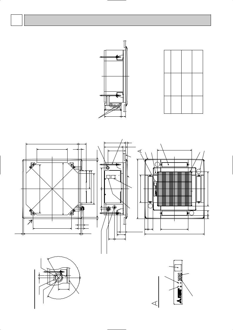
4 OUTLINES AND DIMENSIONS
SLZ-KA25VAL.TH
SLZ-KA35VAL.TH
SLZ-KA50VAL.TH
SLZ-KA25VA.TH
SLZ-KA35VA.TH
SLZ-KA50VA.TH
SLZ-KA25VAL1.TH
SLZ-KA35VAL1.TH
SLZ-KA50VAL1.TH
SLZ-KA25VA1.TH
SLZ-KA35VA1.TH
SLZ-KA50VA1.TH
|
|
|
Wiring entry |
|
|
570 |
|
87 |
Drain pipe |
VP-25 connection |
(O.D. { 32) |
|
15~37 |
|
|
||
335 |
31 |
|
|
|
|
|
|
|
|
|
|
530 |
Suspension bolt pitch |
570 |
199 352 335 |
576~620 Ceiling hole |
202 230 |
|
|
|
|
|
|
|
|
17 |
|
15~37 |
Freshair intake |
576~620Ceilinghole |
|
56 |
15~37 |
(gas) |
(liquid) |
|
|
15~37 |
|||||||
|
|
Suspension bolt pitch |
|
|
|
|
||
|
|
|
420 |
|
57 |
|
|
|
|
|
|
outhole |
|
|
|
Refrigerent pipe |
Refrigerent pipe |
|
|
73.4 |
|
120 |
|
|
|
|
|
|
|
|
|
° |
|
|
|
|
|
{ Cut |
|
|
|
|
|
|
|
air intake |
25 |
|
|
|
|
|
|
|
fresh |
{100 |
{hole2.8-3 holeBurring |
|
surfaceCeiling |
|
|
|
|
drawingDetailof |
118 |
|
|
|
|||
|
|
|
|
|
|
|
|
|
|
|
|
|
|
° |
|
|
|
|
|
|
|
|
120 |
|
|
|
Unit : mm
182
235 208 193
66
48 |
|
|
Suspension bolt M10 or 3/8 (procure locally) |
|
label |
20 |
|
Brand |
|
|
|
0 |
27 |
|
+5 |
|
|
|
|
|
Ceiling surface |
|
|
Grille |
Terminal block |
650 301 outlet hole |
|
controller) |
Air |
Terminal block |
(Case of Wired remote |
|
loweredge |
||
Suspensionbolt |
||
|
|
38~58 |
93 121
Refrigerent pipe |
(gas) |
{ 9.52mm flared connection |
3/8 inch |
{ 9.52mm flared connection |
3/8 inch |
{ 12.7mm flared connection |
1/2 inch |
Refrigerent pipe |
(liquid) |
{ 6.35mm flared connection |
1/4 inch |
{ 6.35mm flared connection |
1/4 inch |
{ 6.35mm flared connection |
1/4 inch |
Models |
SLZ-KA25VA(L) |
|
SLZ-KA35VA(L) |
|
SLZ-KA50VA(L) |
||
Grille |
Drainhole |
Auto vane |
Airintakehole |
Airintake grille |
Vanemotor |
|
|
|
377 |
|
|
|
|
V/M |
|
|
|
|
|
|
|
V/M |
|
377 Air intake hole
V/M
V/M |
55 |
|
35 |
|
|
|
Airoutlethole |
|
|
35 |
55 |
|
301 |
|
|
|
|
|
650 |
|
|
|
PANEL)(WIRELESS |
lampOperation |
lampBYDEFROST/STAND |
switch(cooling) |
switch(heating)operationEmergency |
|
Emergencyoperation |
||||
|
|
|
Receiver |
|
|
8

Unit : mm
WIRELESS REMOTE CONTROLLER
57 |
17.5 |
|
|
|
h |
|
|
ON/OFF |
TOO |
TOO |
|
|
|
WARM |
COOL |
|
|
AUTO COOL |
FAN |
SELECT |
|
140 |
|
|
||
HEAT DRY |
VANE |
TIME |
||
|
||||
|
MODE |
|
|
|
|
|
|
RESET |
D
B
A
C
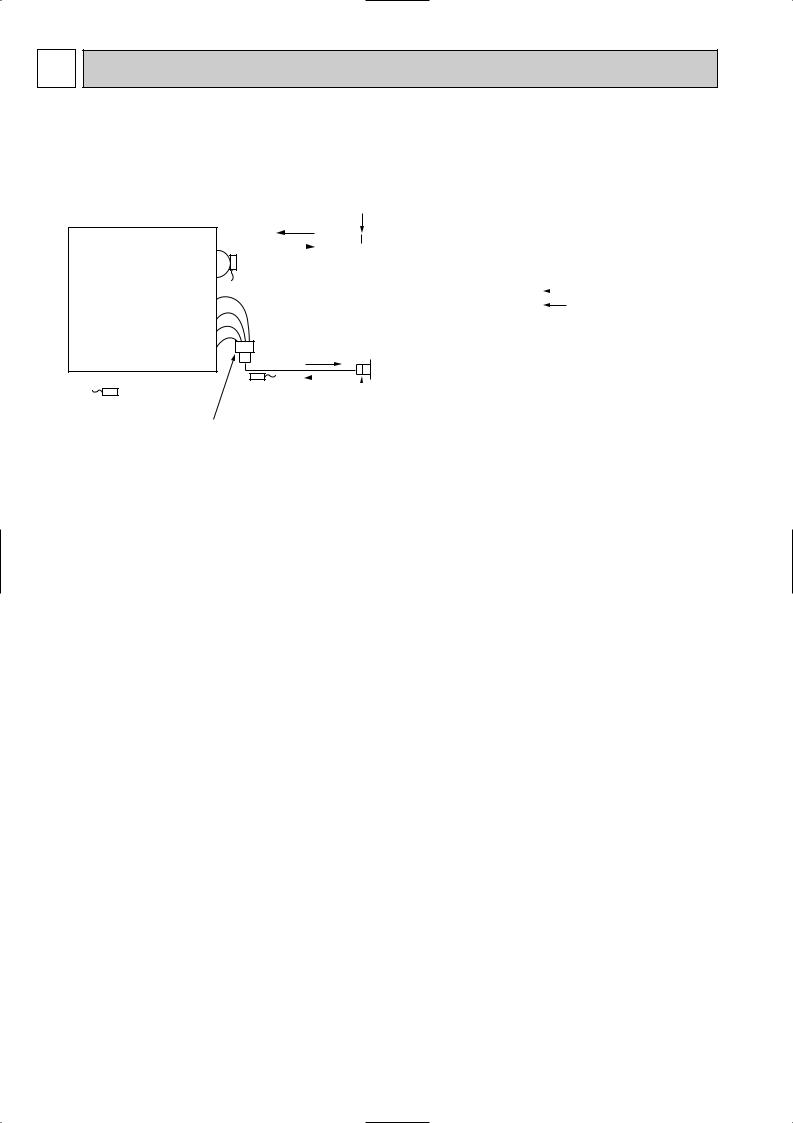
Installation area
•Area in which the remote controller is not exposed to direct sunshine
•Area in which there is no heating source nearby
•Area in which the remote controller is not exposed to cold (or hot) winds
•Area in which the remote controller can be operated easily
•Area in which the remote controller is beyond the reach of children
Installation method
1 Attach the remote controller holder to the desired location using 2 tapping screws. 2 Insert the lower end of the controller into the holder.
A Wireless remote controller (Accessory) B Wall
C Remote controller holder (Accessory) D Fixing screw (Accessory)
•The signal can travel up to approximately 7 meters (in a straight line) within 45 degrees to both right and left of the center line of the receiver.
In addition, the signal may not be received if there is interference of light of fluorescent lights or strong sunlight.
9

Unit : mm
WIRED REMOTE CONTROLLER
130
120
43.5
19
10
5 
 WIRING DIAGRAM
SLZ-KA25VAL.TH SLZ-KA35VAL.TH SLZ-KA50VAL.TH
SLZ-KA25VA.TH SLZ-KA35VA.TH SLZ-KA50VA.TH
SLZ-KA25VAL1.TH SLZ-KA35VAL1.TH SLZ-KA50VAL1.TH
SLZ-KA25VA1.TH SLZ-KA35VA1.TH SLZ-KA50VA1.TH
GRILLE
MV |
|
BLU |
|
5 |
|
1 |
|
|
|
||
|
|
WHT |
|
MV |
|
2 |
|
|
YLW |
||
5 |
|
3 |
|
|
ORN |
||
5 |
|
6 |
|
MV |
|
RED |
|
|
|
||
5 |
|
7 |
|
|
|
||
MV |
|
YLW |
4 |
|
|
||
5 |
|
5 |
|
|
YLW |
||
|
|
10 |
|
|
|
|
|
H2 |
|
|
8 |
|
|
9 |
|
|
|
|
|
|
|
BRN |
1 |
|
|
RED |
|
|
|
2 |
|
|
|
ORN |
|
W.B |
|
3 |
|
|
YLW |
4 |
|
|
9 |
BLU |
|
|
|
||
CNB |
|
5 |
|
|
VLT |
||
|
|
6 |
|
|
|
GRY |
|
BZ |
|
7 |
|
|
PINK |
||
|
|
8 |
|
|
|
|
|
LED2 |
SKY BLU |
9 |
|
|
|
||
LED1
SW1
SW2
RU
REMOTE
CONTROLLER
W.R
[LEGEND]
ORN
C1 RED
SWE |
SW3 |
|
ON |
ON |
|
OFF |
OFF |
|
1 2 3 4 5 |
||
|
SW2
ON
OFF
1 2 3 4 5
CN32
See fig:w1
TB4
S1 |
|
|
S2 |
TO OUTDOOR UNIT |
|
S3 |
||
|
|
|
MF |
|
|
|
|
|
|
|
|
|
DP |
|
|
|
|
|
|
|
|
|
|
|
|
|
|
|
|
||
|
|
|
|
|
|
|
|
|
|
|
|
|
|
|
|
|
|
|
|
|
|
|
|
|
|
|
|
|
||
|
|
|
|
|
|
|
|
|
|
|
|
|
|
|
|
|
|
|
|
|
|
|
|
|
|
|
|
|
|
P.B |
|
|
|
|
|
|
|
|
|
|
|
|
|
1 |
2 |
|
|
|
|
|
|
|
|
|
|
|
|
1 2 |
3 |
AC220-240V |
|
|
|
|
|
|
|
|
|
|
|
|
|
|
|
|
|
|
|
|
|
|
|
|
|
|
|
|
||||
|
YLW |
BRN |
WHT |
BLU |
|
|
YLW |
YLW |
|
|
|
YLW |
|
YLW |
|
|
|
RED |
WHT |
RED |
|
|
ORN |
|
|
|
CNSK(RED) |
|||
BLK |
|
|
|
|
|
|
|
|
|
BLU |
|
BLU |
I.B |
|
|
|
|
|
||||||||||||
|
|
|
|
WHT |
|
|
|
|
|
RED |
|
|
|
BLU |
|
|
|
RED |
|
ORN |
|
|
|
|
|
|
TRANS |
|||
1 |
3 |
5 |
7 9 (FAN) |
|
|
1 |
3 |
(D·HEATER) |
1 |
3 |
(D·U·M) |
|
1 |
3 (POWER |
1 3 |
(POWER) |
|
1 3 |
|
|
|
|
||||||||
|
|
|
|
|
|
|
|
|
|
|||||||||||||||||||||
|
|
|
|
FAN |
|
|
|
|
|
CNC |
|
|
|
CNP |
|
|
|
BOARD) |
|
CND |
|
BLU |
|
|
|
|
|
|
||
|
|
|
|
|
|
|
|
|
|
|
|
|
|
|
|
|
|
|
CNDK |
|
|
|
|
|
|
|
|
|||
|
|
|
|
|
|
|
|
|
|
|
|
|
|
|
|
|
|
|
|
|
|
(CONTROL) |
|
|
|
|
|
|
||
|
|
|
|
|
|
|
|
|
|
|
|
X1 |
|
|
|
|
|
|
|
FUSE |
|
|
|
|
|
|
|
|
||
|
|
|
|
|
|
|
|
|
|
|
|
|
|
|
|
|
|
|
|
|
CN3C |
|
|
|
|
|
|
|||
|
|
|
|
|
|
|
|
|
|
|
|
|
|
|
|
|
|
|
|
|
|
|
|
|
|
|
1 |
2 |
CN2S(WHT)DC13.1V |
|
X6 X5 X4 |
X7 |
|
|
|
|
|
|
|
|
|
|
|
|
|
|
|
ZNR |
|
|
|
|
|
|
|
|
|
|
|||
X6 X5 X4 |
X7 |
|
|
|
|
|
|
|
|
X1 |
|
|
|
|
|
|
|
|
|
WHT |
1 |
BLK |
|
|
|
|
||||
|
|
|
|
|
|
|
|
|
|
|
|
|
|
|
|
(POWER |
WHT |
|
|
|
|
|||||||||
|
|
|
|
|
|
|
|
|
|
|
|
|
|
|
|
|
|
|
|
|
|
|
|
BOARD) |
2 |
|
|
|
|
|
|
|
|
|
|
|
|
|
|
|
|
|
|
|
|
|
|
|
|
|
|
|
|
|
CN2D |
|
|
|
|
|
|
|
|
|
|
|
|
|
|
|
|
|
|
|
|
|
|
|
|
|
|
LED3 |
|
|
|
|
|
|
<fig:w1> |
|
||
CN2L |
|
|
|
|
|
|
|
|
|
|
|
|
|
|
|
|
|
|
|
|
|
|
LED1 |
|
MODELS |
SW2 |
||||
|
|
|
|
|
|
|
|
|
|
|
|
|
|
|
|
|
|
|
|
|
LED2 |
|
|
|
|
|
|
|
||
|
|
|
|
|
|
|
GRN |
|
|
|
|
|
|
|
|
|
|
|
|
BLK |
RED |
|
|
|
|
KA25 |
ON |
|||
|
|
|
|
|
|
|
|
|
|
|
|
|
|
|
|
|
|
|
|
|
|
|
|
OFF |
||||||
|
|
|
|
|
|
(VANE) |
|
|
|
|
|
|
|
|
|
|
|
(2 PHASE) (INTAKE) |
|
|
|
|
|
|||||||
|
|
|
|
|
|
|
|
|
|
|
|
|
|
|
|
|
|
|
|
|
|
|
|
1 2 3 4 5 |
||||||
|
|
|
|
|
|
CN6V |
|
|
|
|
|
CN90 |
|
|
|
|
WHT |
CN29 |
CN20 |
WHT |
BLU |
|
|
|
|
ON |
||||
|
|
|
|
|
|
|
|
|
|
|
|
|
|
|
|
|
|
|
|
|
|
KA35 |
||||||||
|
|
|
|
|
1 |
2 |
3 |
4 |
5 |
6 |
|
(WIRELESS) |
|
|
|
(DRAIN) |
1 2 |
1 2 |
(LIQUID) |
(REMOCON) |
|
|
OFF |
|||||||
CN51 |
|
CN41 |
BLU |
WHT |
YLW |
ORN |
RED |
|
|
|
|
WHT |
|
|
|
|
CN31 |
|
|
CN21 |
CN22 |
|
|
|
|
1 2 3 4 5 |
||||
|
1 |
2 |
3 |
|
7 |
8 |
|
9 |
|
|
|
|
KA50 |
OFF |
||||||||||||||||
|
|
|
|
|
|
4 5 |
6 |
|
1 2 3 |
|
|
1 2 |
1 |
2 |
|
|
||||||||||||||
|
|
|
|
|
|
|
|
|
|
|
|
|
|
|
|
|
|
|
|
|
|
|
|
|
|
|
|
|
|
ON |
|
|
|
|
|
|
|
|
|
|
|
|
|
|
|
|
|
|
|
|
|
|
|
|
|
|
|
|
|
|
1 2 3 4 5 |
|
|
|
|
|
|
|
|
|
|
BRN |
RED |
ORN |
YLW |
BLU |
VLT |
GRY |
PINK |
|
SKYBLU |
|
|
|
|
BLU BLU |
|
* Case of wired model |
||||
|
|
|
|
|
|
|
|
5 |
|
|
|
|
|
|
9 |
|
|
|
|
|
|
|
|
|
|
|
|
|
|
|
|
|
|
|
|
|
|
|
|
|
|
|
|
|
|
|
|
|
|
|
|
|
|
|
|
|
|
|
|
|
|
|
|
|
|
|
|
|
|
|
|
|
|
|
|
|
|
|
|
|
|
|
|
|
|
|
TB15 |
|
|
|
|
|
|
|
|
|
|
|
|
|
|
|
|
|
|
|
|
|
|
|
|
|
|
|
|
|
|
|
1 |
TO MA-REMOTE |
|||
|
|
|
|
|
|
|
|
|
|
|
|
|
|
|
|
|
|
|
|
|
|
|
|
|
|
2 |
||||
|
|
|
|
|
|
|
|
|
|
|
|
|
|
|
|
|
|
|
|
|
|
|
|
|
|
} CONTROLLER |
||||
|
|
|
|
|
|
|
|
|
|
|
|
|
|
|
|
|
|
|
|
|
|
|
|
|
|
|
||||
|
|
|
|
|
|
|
|
|
|
|
|
|
|
|
|
|
|
|
|
DS |
TH5 |
TH1 |
TH2 |
|
|
|
DC8.7-13V |
|||
* Case of wireress model
SYMBOL |
NAME |
SYMBOL |
NAME |
|
P.B |
INDOOR POWER BOARD |
W.B |
WIRELESS REMOTE CONTROLLER BOARD |
|
I.B |
INDOOR CONTROLLER BOARD |
RU |
RECEIVING UNIT |
|
CN2L |
CONNECTOR(LOSSNAY) |
BZ |
BUZZER |
|
CN32 |
CONNECTOR(REMOTE SWITCH) |
LED1 |
LED(RUN INDICATOR) |
|
CN41 |
CONNECTOR(HA TERMINAL-A) |
LED2 |
LED(HOT ADJUST) |
|
CN51 |
CENTRALLY CONTROL |
SW1 |
SWITCH(HEATING ON/OFF) |
|
FUSE |
FUSE(T6.3AL250V) |
SW2 |
SWITCH(COOLING ON/OFF) |
|
LED1 |
POWER SUPPLY(I.B) |
C1 |
CAPACITOR(FAN MOTOR) |
|
LED2 |
POWER SUPPLY(I.B) |
DP |
DRAIN PUMP |
|
LED3 |
TRANSMISSION(INDOOR-OUTDOOR) |
DS |
DRAIN SENSOR |
|
SW2 |
SWITCH(CAPACITY CODE) |
H2 |
DEW PREVENTION HEATER |
|
SW3 |
SWITCH(MODE SELECTION) |
MF |
FAN MOTOR |
|
SWE |
SWITCH(EMERGENCY OPERATION) |
MV |
VANE MOTOR |
|
X1 |
DRAIN PUMP/DEW PREVENTION HEATER |
TB4 |
TERMINAL BLOCK(INDOOR/OUTDOOR CONNECTING LINE) |
|
X4 |
RELAY(FAN MOTOR LL) |
TB15 |
TERMINAL BLOCK(REMOTE CONTROLLER |
|
X5 |
RELAY(FAN MOTOR Lo) |
TRANSMISSION LINE) |
||
|
||||
X6 |
RELAY(FAN MOTOR Hi) |
TH1 |
ROOM TEMP.THERMISTOR |
|
X7 |
RELAY(FAN MOTOR Me) |
(0°C/15kΩ , 25°C/5.4kΩ DETECT) |
||
|
||||
ZNR |
VARISTOR |
TH2 |
PIPE TEMP.THERMISTOR/LIQUID |
|
|
|
(0°C/15kΩ , 25°C/5.4kΩ DETECT) |
||
|
|
|
||
|
|
TH5 |
COND./EVA.TEMP.THERMISTOR |
|
|
|
(0°C/15kΩ , 25°C/5.4kΩ DETECT) |
||
|
|
|
NOTES : 1. |
Since the outdoor side electric wiring may change, be sure to check the outdoor unit electric wiring for servicing. |
||
2. |
Indoor and outdoor connecting wires have polarities, make sure to match terminal numbers(S1,S2,S3) for correct wiring. |
||
3. |
Symbols used in wiring diagram above are, |
: Connector, |
: Terminal (block). |
w For details on how to operate self-diagnosis, refer to the technical manuals etc.
11
6 REFRIGERANT SYSTEM DIAGRAM
SLZ-KA25VAL.TH SLZ-KA35VAL.TH SLZ-KA50VAL.TH
SLZ-KA25VA.TH SLZ-KA35VA.TH SLZ-KA50VA.TH
SLZ-KA25VAL1.TH SLZ-KA35VAL1.TH SLZ-KA50VAL1.TH
SLZ-KA25VA1.TH SLZ-KA35VA1.TH SLZ-KA50VA1.TH
Strainer #50
Heat exchanger
|
|
|
|
|
|
|
|
|
|
|
|
|
|
|
|
|
|
|
|
|
Refrigerant GAS pipe connection |
|||
|
|
|
|
|
|
|
|
|
|
|
|
|
|
|
|
|
|
|
|
|
(Flare) |
|||
|
|
|
|
|
|
|
|
|
|
|
|
|
|
|
|
|
|
|
|
|
||||
|
|
|
|
|
|
|
|
|
|
|
|
|
|
|
||||||||||
|
|
|
|
|
|
|
|
|
|
|
|
|
Condenser/evaporator |
|||||||||||
|
|
|
|
|
|
|
|
|
|
|
|
|
||||||||||||
|
|
|
|
|
|
|
|
|
|
|
|
|
temperature thermistor |
|||||||||||
|
|
|
|
|
|
|
|
|
|
|
|
|
||||||||||||
|
|
|
|
|
|
|
|
|
|
|
|
|
(TH5) |
|
||||||||||
|
|
|
|
|
|
|
|
|
|
|
|
|
|
|
|
|||||||||
|
|
|
|
|
|
|
|
|
|
|
|
|
|
|
|
|
|
|
|
|
|
|
|
Refrigerant flow in cooling |
|
|
|
|
|
|
|
|
|
|
|
|
|
|
|
|
|
|
|
|
|
|
|
|
|
|
|
|
|
|
|
|
|
|
|
|
|
|
|
|
|
|
|
|
|
|
|
|
|
Refrigerant flow in heating |
|
|
|
|
|
|
|
|
|
|
|
|
|
|
|
|
|
|
|
|
|
|
|
||
|
|
|
|
|
|
|
|
|
|
|
|
|
|
|
|
|
|
|
|
|
Refrigerant LIQUID pipe connection |
|||
|
|
|
|
|
|
|
|
|
|
|
|
|
|
|
|
|
|
|
|
|
||||
|
|
|
|
|
|
|
|
|
|
|
|
|
|
|
|
|
|
|
|
|
||||
|
|
|
|
|
|
|
|
|
|
|
|
|
|
|
|
|
|
|
|
|
||||
|
|
|
|
|
|
|
|
|
|
|
|
|
|
|
|
|
|
|
|
|
||||
|
|
|
|
|
|
|
|
|
|
|
|
|
|
|
||||||||||
|
|
|
|
|
|
|
|
|
|
|
|
|
|
|
|
|
|
|
|
|
(Flare) |
|||
|
|
|
|
|
|
|
|
|
|
|
|
|
Pipe temperature |
|
|
|||||||||
|
|
|
|
|
|
|
|
|
|
|
|
|
|
|||||||||||
Room temperature |
|
|
|
|
|
|
|
thermistor/liquid |
|
|
||||||||||||||
thermistor (TH1) |
|
|
|
|
|
|
|
(TH2) |
|
|
||||||||||||||
|
|
|
|
|
|
|
|
|||||||||||||||||
|
|
|
|
|
|
Distributor |
|
|
|
|
Strainer |
|||||||||||||
|
|
|
|
|
|
#50 |
|
|
|
|
||||||||||||||
|
|
|
|
|
|
with strainer |
|
|
|
|
||||||||||||||
|
|
|
|
|
|
|
|
|
|
|
|
|
|
|
|
|
|
|||||||
|
|
|
|
|
|
#50 |
|
|
|
|
|
|
|
|
|
|
|
|
|
|
|
|
||
12
 Loading...