


WORKSHOP MANUAL
SUPPLEMENT
FOREWORD
This manual outlines changes in servicing procedures related to the chassis including vehicle inspections, adjustments, and improvements in the newly equipped models. Use the following manuals in combination with this manual required.
TECHNICAL INFORMATION MANUAL PYDE9802
WORKSHOP MANUAL |
|
CHASSIS GROUP |
PWDE9803 |
ENGINE GROUP |
PWEEjjjj |
|
(Looseleaf edition) |
ELECTRICAL WIRING |
PHDE9802 |
|
PHDE9802- A |
BODY REPAIR MANUAL |
PBDE9802 |
PARTS CATALOGUE |
|
SPACE RUNNER |
B608V500Aj |
SPACE WAGON |
B608W500Aj |
All information, illustrations and product descriptions contained in this manual are current as at the time of publication. We, however, reserve the right to make changes at any time without prior notice or obligation.
“GDI” is the trade mark which Mitsubishi Motors Corporation holds.
E Mitsubishi Motors Corporation |
May 1999 |
General . . . . . . . . . . . . . . . . . . . . . . . .
Engine . . . . . . . . . . . . . . . . . . . . . . . . .
Fuel . . . . . . . . . . . . . . . . . . . . . . . . . . .
Engine Cooling . . . . . . . . . . . . . . . . .
Intake and Exhaust . . . . . . . . . . . .
Engine Electrical . . . . . . . . . . . . . . .
Engine and Emission Control . . . .
Clutch . . . . . . . . . . . . . . . . . . . . . . . . .
Automatic Transmission . . . . . . . .
Front Axle . . . . . . . . . . . . . . . . . . . . . .
Wheel and Tyre . . . . . . . . . . . . . . . . .
Front Suspension . . . . . . . . . . . . . . .
Service Brakes . . . . . . . . . . . . . . . . .
Steering . . . . . . . . . . . . . . . . . . . . . . . .
00
11
13
14
15
16
17
21
23
26
31
33
35
37

WORKSHOP MANUAL
FOREWORD
This Workshop Manual contains procedures for service mechanics, including removal, disassembly, inspection, adjustment, reassembly and installation. Use the following manuals in combination with this manual as required.
TECHNICAL INFORMATION MANUAL
|
IMXE99E1 |
WORKSHOP MANUAL |
|
ENGINE GROUP |
PWEE |
|
(Looseleaf edition) |
ELECTRICAL WIRING |
EMXE99E1 |
BODY REPAIR MANUAL |
BMXE99E1 |
PARTS |
N606H509D |
All information, illustrations and product descriptions contained in this manual are current as at the time of publication. We, however, reserve the right to make changes at any time without prior notice or obligation.
General . . . . . . . . . . . . . . . . . . . . . . . .
Engine . . . . . . . . . . . . . . . . . . . . . . . . .
Engine Lubrication . . . . . . . . . . . . . .
Fuel . . . . . . . . . . . . . . . . . . . . . . . . . . . .
Engine Cooling . . . . . . . . . . . . . . . . .
Intake and Exhaust . . . . . . . . . . . . .
Engine Electrical . . . . . . . . . . . . . . . .
Engine and Emission Control . . . .
Clutch . . . . . . . . . . . . . . . . . . . . . . . . . .
Manual Transmission . . . . . . . . . . . .
Front Axle . . . . . . . . . . . . . . . . . . . . . .
Rear Axle . . . . . . . . . . . . . . . . . . . . . . .
Wheel and Tyre . . . . . . . . . . . . . . . . .
Power Plant Mount . . . . . . . . . . . . . .
Front Suspension . . . . . . . . . . . . . . .
Rear Suspension . . . . . . . . . . . . . . . .
Service Brakes . . . . . . . . . . . . . . . . . .
Parking Brakes . . . . . . . . . . . . . . . . .
Steering . . . . . . . . . . . . . . . . . . . . . . . .
Body . . . . . . . . . . . . . . . . . . . . . . . . . . .
Exterior . . . . . . . . . . . . . . . . . . . . . . . .
Interior and Supplemental
Restrain System (SRS) . . . . . . . . .
Chassis Electrical . . . . . . . . . . . . . . .
Heater, Air Conditioner and
Ventilation . . . . . . . . . . . . . . . . . . . . .
ªGDI is the trade mark which Mitsubishi Motors Corporation holds.
E Mitsubishi Motors Corporation |
September 1998 |
00
11
12
13
14
15
16
17
21
22
26
27
31
32
33
34
35
36
37
42
51
52
54
55
WARNING!
(1)Improper service or maintenance of any component of the SRS and seat belt with pre-tensioner, or any SRS-related component, can lead to personal injury or death to service personnel (from inadvertent firing of the air bag and seat belt with pre-tensioner) or to the driver and passenger (from rendering the SRS inoperative).
(2)SRS components and seat belt with pre-tensioner should not be subjected to heat, so remove the SRS-ECU, air bag module, clock spring and seat belt with pre-tensioner before drying or baking the vehicle after painting.
SRS-ECU, air bag module, clock spring and side impact sensor: 93_C or more Seat belt with pre-tensioner: 90_C or more
(3)Service or maintenance of any SRS component and seat belt with pre-tensioner or SRS-related component must be performed only at an authorized MITSUBISHI dealer.
(4)MITSUBISHI dealer personnel must thoroughly review this manual, and especially its GROUP 52B ± Supplemental Restraint System (SRS), before beginning any service or maintenance of any component of the SRS and seat belt with pre-tensioner or any SRS-related component.
NOTE
Section titles with asterisks (*) in the table of contents in each group indicate operations requiring warnings.

00-1
GENERAL
CONTENTS
HOW TO USE THIS MANUAL . . . . . . . . . . . . . . |
2 |
Chassis Number . . . . . . . . . . . . . . . . . . . . . . . . . . . . . |
4 |
|
Model Indications . . . . . . . . . . . . . . . . . . . . . . . . . . . . |
2 |
Engine Model Number . . . . . . . . . . . . . . . . . . . . . . . . |
5 |
|
VEHICLE IDENTIFICATION |
3 |
New Vehicles . . . . . . . . . . . . . . . . . . . . . . . . . . . . . . . . |
5 |
|
|
|
|
||
Models . . . . . . . . . . . . . . . . . . . . . . . . . . . . . . . . . . . . . . |
3 |
MAJOR SPECIFICATIONS . . . . . . . . . . . . . . . . . . |
6 |
|
Model Code . . . . . . . . . . . . . . . . . . . . . . . . . . . . . . . . . |
3 |
|
|
|
|
|
|
|
|
|
|
|
|
|

00-2 |
GENERAL - How to Use This Manual |
|
|
HOW TO USE THIS MANUAL
MODEL INDICATIONS
The following abbreviations are used in this manual for classification of model types.
2000: Indicates models equipped with the 2,000 mL <4G63> petrol engine. 2400: Indicates models equipped with the 2,400 mL <4G64> petrol engine.
MPI: Indicates the multipoint injection, or engine equipped with the multipoint injection.
GDI: Indicates the gasoline direct injection, or engine equipped with the gasoline direct injection. SOHC: Indicates an engine with the single overhead camshaft, or models equipped with such an
engine.
DOHC: Indicates an engine with the double overhead camshaft, or models equipped with such an engine.
M/T: Indicates the manual transmission, or models equipped with the manual transmission. A/T: Indicates the automatic transmission, or models equipped with the automatic transmission. A/C: Indicates the air conditioner.

|
GENERAL - Vehicle Identification |
00-3 |
||
|
|
|
|
|
VEHICLE IDENTIFICATION |
|
|
|
|
MODELS |
|
|
|
|
|
|
|
|
|
Model code |
|
Engine model |
Transmission model |
Fuel supply system |
|
|
|
|
|
N63W |
SNUEL6/R6 |
4G63-SOHC (1,997 mL) |
F5M42 (2WD-5M/T) |
MPI |
|
|
|
|
|
|
SNFEL6 |
|
|
|
|
|
|
|
|
|
SNUJL6 |
|
|
|
|
|
|
|
|
|
SRUEL6/R6 |
|
F4A42 (2WD-4A/T) |
|
|
|
|
|
|
|
SRFEL6 |
|
|
|
|
|
|
|
|
|
SRUJL6 |
|
|
|
|
|
|
|
|
N64W |
SNHCL6 |
4G64-DOHC-GDI |
F5M42 (2WD-5M/T) |
GDI |
|
|
(2,351 mL) |
|
|
|
SNGCL6 |
|
|
|
|
|
|
|
|
|
|
|
|
|
|
SNHGL6 |
|
|
|
|
|
|
|
|
|
SRHCL6 |
|
F4A42 (2WD-4A/T) |
|
|
|
|
|
|
|
SRGCL6 |
|
|
|
|
|
|
|
|
|
SRHGL6 |
|
|
|
|
|
|
|
|
MODEL CODE
|
|
|
|
|
|
|
|
|
|
No. |
Items |
Contents |
|
|
|
|
|
|
|
|
|
|
|
|
|
|
|
|
|
|
|
|
|
|
|
1 |
Development |
N6: SPACE RUNNER |
|
|
|
|
|
|
|
|
|
|
|
|
(2WD) |
|
|
|
|
|
|
|
|
|
|
|
|
|
|
|
|
|
|
|
|
|
|
|
2 |
Engine type |
3: 2,000 mL petrol engine |
|
|
|
|
|
|
|
|
|
|
|
|
4: 2,400 mL petrol engine |
|
|
|
|
|
|
|
|
|
|
|
|
|
|
|
|
|
|
|
|
|
|
|
3 |
Body type |
W: Wagon |
|
|
|
|
|
|
|
|
|
|
|
|
|
|
|
|
|
|
|
|
|
|
|
4 |
Body style |
S: 3-door station wagon |
|
|
|
|
|
|
|
|
|
|
|
|
|
1 |
2 |
3 |
4 |
5 |
6 |
7 |
8 |
9 |
|
5 |
Transmission type |
N: 5-speed manual |
|
|
|
transmission |
|||||||||
|
|
|
|
|
|
|
|
|
|
|
|
R: 4-speed automatic |
|
|
|
|
|
|
|
|
|
|
|
|
transmission |
|
|
|
|
|
|
|
|
|
|
|
|
|
|
|
|
|
|
|
|
|
|
|
6 |
Trim level |
U,F,H,G: GLX |
|
|
|
|
|
|
|
|
|
|
|
|
|
|
|
|
|
|
|
|
|
|
|
7 |
Specification engine |
E,J: MPI-SOHC |
|
|
|
|
|
|
|
|
|
|
|
feature |
C,G: GDI-DOHC |
|
|
|
|
|
|
|
|
|
|
|
|
|
|
|
|
|
|
|
|
|
|
|
8 |
Steering wheel location |
L: Left hand |
|
|
|
|
|
|
|
|
|
|
|
|
R: Right hand |
|
|
|
|
|
|
|
|
|
|
|
|
|
|
|
|
|
|
|
|
|
|
|
9 |
Destination |
6: For Europe |
|
|
|
|
|
|
|
|
|
|
|
|
|

00-4 |
GENERAL - Vehicle Identification |
|
|
CHASSIS NUMBER
1 |
2 |
3 |
4 |
5 |
6 |
7 |
8 |
9 |
10 |
11 |
No. |
Items |
|
Contents |
|
|
|
|
1 |
Fixed figure |
J |
Asia |
|
|
|
|
2 |
Distribution channel |
M |
Japan channel |
|
|
|
|
3 |
Destination |
A |
For Europe, right hand drive |
|
|
|
|
|
|
B |
For Europe, left hand drive |
|
|
|
|
4 |
Body style |
S |
3-door station wagon |
|
|
|
|
5 |
Transmission type |
N |
5-speed manual transmission |
|
|
|
|
|
|
R |
4-speed automatic transmission |
|
|
|
|
6 |
Development order |
N6 |
SPACE RUNNER (2WD) |
|
|
|
|
7 |
Engine |
3 |
4G63: 1,997 mL petrol engine |
|
|
|
|
|
|
4 |
4G64: 2,351 mL petrol engine |
|
|
|
|
8 |
Sort |
W |
Station wagon |
|
|
|
|
9 |
Model year |
Y |
2000 |
|
|
|
|
10 |
Plant |
Z |
Okazaki Motor Vehicle Works |
|
|
|
|
11 |
Serial number |
- |
- |
|
|
|
|
GENERAL - Vehicle Identification |
00-5 |
|
|
ENGINE MODEL NUMBER
1. |
The engine model number is stamped at the cylinder |
||
|
|
block as shown in the following. |
|
|
|
|
|
|
|
Engine model |
Engine displacement mL |
|
|
|
|
|
|
4G63 |
1,997 |
|
|
4G64 |
2,351 |
|
|
|
|
2. |
The engine serial number is stamped near the engine |
||
|
|
model number. |
|
|
|
|
|
|
|
Engine serial number |
AA0201 to YY9999 |
|
|
|
|
NEW VEHICLES
New vehicles has been added as shown below.
New vehicle has been developed from the respective basic vehicle. Specification show only a particular part of the new vehicle. For the remaining par, refer to specifications for basic vehicle.
New vehicle |
Basic vehicle |
|
|
N63W SNUEL6 |
N61W SNUCL6 |
|
|
N63W SNUER6 |
N61W SNUCR6 |
|
|
N63W SNFEL6 |
N61W SNFCL6 |
|
|
N63W SNUJL6 |
N61W SNUGL6 |
|
|
N63W SRUEL6 |
N61W SRUCL6 |
|
|
N63W SRUER6 |
N61W SRUCR6 |
|
|
N63W SRFEL6 |
N61W SRFCL6 |
|
|
N63W SRUJL6 |
N61W SRUGL6 |
|
|
N64W SNHCL6 |
N61W SNUCL6 |
|
|
N64W SNGCL6 |
N61W SNFCL6 |
|
|
N64W SNHGL6 |
N61W SNUGL6 |
|
|
N64W SRHCL6 |
N61W SRUCL6 |
|
|
N64W SRGCL6 |
N61W SRFCL6 |
|
|
N64W SRHGL6 |
N61W SRUGL6 |
|
|

00-6 |
GENERAL - Major Specifications |
|
|
MAJOR SPECIFICATIONS
|
|
|
|
|
|
|
|
|
3 |
3* |
|
|
5 |
|
|
9 |
4 |
8 |
|
|
6 |
||
|
|
|
7 |
|
|
||||||
|
2 |
|
|
|
1 |
|
|
|
|
||
|
|
|
|
|
|
|
|
|
|
|
|
Items |
|
|
|
|
N63W |
|
N63W |
|
N64W |
N64W |
|
|
|
|
|
|
SNUEL6, |
|
SRUEL6, |
|
SNHCL6, |
SRHCL6, |
|
|
|
|
|
|
SNUER6, |
|
SRUER6, |
|
SNGCL6, |
SRGCL6, |
|
|
|
|
|
|
SNFEL6, |
|
SRFEL6, |
|
SNHGL6 |
SRHGL6 |
|
|
|
|
|
|
SNUJL6 |
|
SRUJL6 |
|
|
|
|
|
|
|
|
|
|
|
|
|
|
|
|
Vehicle |
|
Overall length |
|
1 |
4,290 |
|
|
|
|
|
|
dimensions |
|
|
|
|
|
|
|
|
|
|
|
|
Overall width |
|
2 |
1,695 |
|
|
|
|
|
|
|
mm |
|
|
|
|
|
|
|
|
|||
|
|
|
|
|
|
|
|
|
|
|
|
|
Overall height |
|
3 |
1,650 |
|
|
|
|
|
|
|
|
|
|
|
|
|
|
|
|
|||
|
|
(unladen) |
|
|
1,680* |
|
|
|
|
|
|
|
|
|
|
|
|
|
|
|
|
|
|
|
|
Wheelbase |
|
4 |
2,550 |
|
|
|
|
|
|
|
|
|
|
|
|
|
|
|
|
|
|
|
|
Track-front |
|
5 |
1,460 |
|
|
|
|
|
|
|
|
|
|
|
|
|
|
|
|
|
|
|
|
Track-rear |
|
6 |
1,465 |
|
|
|
|
|
|
|
|
|
|
|
|
|
|
|
|
|
|
|
|
Overhang-front |
|
7 |
890 |
|
|
|
|
|
|
|
|
|
|
|
|
|
|
|
|
|
|
|
|
Overhang-rear |
|
8 |
850 |
|
|
|
|
|
|
|
|
|
|
|
|
|
|
|
|
|
|
|
|
Ground clear- |
|
9 |
155 |
|
|
|
|
|
|
|
|
ance (unladen) |
|
|
|
|
|
|
|
|
|
Vehicle |
|
Kerb weight |
|
1,360 |
|
1,380 |
|
1,400 |
1,420 |
||
weight kg |
|
|
|
|
|
|
|
|
|
|
|
|
Max. gross vehicle |
|
1,880 |
|
|
|
1,920 |
|
|||
|
|
|
|
|
|
|
|||||
|
|
weight |
|
|
|
|
|
|
|
|
|
|
|
|
|
|
|
|
|
|
|
||
|
|
Max. axle weight |
|
1,000 |
|
|
|
1,050 |
|
||
|
|
rating-front |
|
|
|
|
|
|
|
|
|
|
|
Max. axle weight |
|
900 |
|
|
|
|
|
|
|
|
|
rating-rear |
|
|
|
|
|
|
|
|
|
Seating capacity |
|
5 |
|
|
|
|
|
|
|||
|
|
|
|
|
|
|
|
|
|
||
Engine |
|
Model No. |
|
4G63 |
|
|
|
4G64 |
|
||
|
|
|
|
|
|
|
|
|
|
||
|
|
Total displacement |
|
1,997 |
|
|
|
2,351 |
|
||
|
|
mL |
|
|
|
|
|
|
|
|
|
|
|
|
|
|
|
|
|
|
|
||
Transmis- |
|
Model No. |
|
F5M42 |
|
F4A42 |
|
F5M42 |
F4A42 |
||
sion |
|
|
|
|
|
|
|
|
|
|
|
|
Type |
|
5-speed manual |
|
4-speed |
|
5-speed manual |
4-speed |
|||
|
|
|
|
|
|||||||
|
|
|
|
|
|
|
automatic |
|
|
|
automatic |
|
|
|
|
|
|
|
|
||||
Fuel system |
|
Fuel supply system |
Electronically controlled multipoint |
|
Gasoline Direct Injection |
||||||
|
|
|
|
|
injection |
|
|
|
|
|
|
|
|
|
|
|
|
|
|
|
|
|
|
*: Vehicles with roof rails

11C-1
ENGINE
<4G6-MPI>
CONTENTS
GENERAL . . . . . . . . . . . . . . . . . . . . . . . . . . . . . . . . . 3
Outline of Changes . . . . . . . . . . . . . . . . . . . . . . . . . . 3
GENERAL INFORMATION . . . . . . . . . . . . . . . . . . 3
SERVICE SPECIFICATIONS . . . . . . . . . . . . . . . . . 3
SEALANTS . . . . . . . . . . . . . . . . . . . . . . . . . . . . . . . . 4
SPECIAL TOOLS . . . . . . . . . . . . . . . . . . . . . . . . . . 5
ON-VEHICLE SERVICE . . . . . . . . . . . . . . . . . . . . . 6
Drive Belt Tension Check and Adjustment . . . . . . 6
Ignition Timing Check . . . . . . . . . . . . . . . . . . . . . . . . 9
Idle Speed Check . . . . . . . . . . . . . . . . . . . . . . . . . . . 10
Idle Mixture Check . . . . . . . . . . . . . . . . . . . . . . . . . . 10
Compression Pressure Check . . . . . . . . . . . . . . . . 11
Manifold Vacuum Check . . . . . . . . . . . . . . . . . . . . . 12
Lash Adjuster Check . . . . . . . . . . . . . . . . . . . . . . . . 12
CRANKSHAFT PULLEY . . . . . . . . . . . . . . . . . . 15 CAMSHAFT AND CAMSHAFT OIL SEAL . . 16 OIL PAN . . . . . . . . . . . . . . . . . . . . . . . . . . . . . . . . . 19 CRANKSHAFT OIL SEAL . . . . . . . . . . . . . . . . . 21 CYLINDER HEAD GASKET . . . . . . . . . . . . . . . 24 TIMING BELT . . . . . . . . . . . . . . . . . . . . . . . . . . . . 27 TIMING BELT B . . . . . . . . . . . . . . . . . . . . . . . . . . 31 ENGINE ASSEMBLY . . . . . . . . . . . . . . . . . . . . . 34
11C-2
NOTES

ENGINE <4G6-MPI> - |
General/General Information/ |
11C-3 |
Service Specifications |
GENERAL
OUTLINE OF CHANGES
The following service procedures have been established in line with the addition of vehicles with 4G63-MPI engine.
GENERAL INFORMATION
Items |
|
|
4G63 |
|
|
|
|
Total displacement mL |
|
|
1,997 |
|
|
|
|
Bore ´ Stroke mm |
|
|
85.0 ´ 88.0 |
|
|
|
|
Compression ratio |
|
|
10.0 |
|
|
|
|
Combustion chamber |
|
|
Pentroof type |
|
|
|
|
Camshaft arrangement |
|
|
SOHC |
|
|
|
|
Number of valve |
Intake |
|
8 |
|
|
|
|
|
Exhaust |
|
8 |
|
|
|
|
Valve timing |
Intake |
Opening |
BTDC 11_ |
|
|
|
|
|
|
Closing |
ABDC 53_ |
|
|
|
|
|
Exhaust |
Opening |
BBDC 63_ |
|
|
|
|
|
|
Closing |
ATDC 21_ |
|
|
|
|
Fuel system |
|
|
Electronically controlled multipoint fuel injection |
|
|
|
|
Rocker arm |
|
|
Roller type |
|
|
|
|
Auto-lash adjuster |
|
|
Equipped |
|
|
|
|
SERVICE SPECIFICATIONS
Items |
|
|
|
Standard value |
Limit |
||
|
|
|
|
|
|||
Alternator drive belt checked |
Vibration frequency Hz |
177 |
- 232 |
- |
|||
|
|
|
|
|
|
|
|
|
|
|
Tension N |
343 |
- 588 |
- |
|
|
|
|
|
|
|
||
|
|
|
Deflection (Reference value) mm |
6.7 - 9.8 |
- |
||
|
|
|
|
|
|
|
|
When adjusting |
the |
alternator |
Vibration frequency Hz |
201 |
- 222 |
- |
|
drive belt |
|
|
|
|
|
|
|
|
|
Tension N |
441 |
- 539 |
- |
||
|
|
|
|||||
|
|
|
|
|
|
||
|
|
|
Deflection (Reference value) mm |
7.2 - 8.4 |
- |
||
|
|
|
|
|
|
|
|
When replacing |
the |
alternator |
Vibration frequency Hz |
241 |
- 276 |
- |
|
drive belt |
|
|
|
|
|
|
|
|
|
Tension N |
637 |
- 833 |
- |
||
|
|
|
|||||
|
|
|
|
|
|
||
|
|
|
Deflection (Reference value) mm |
5.0 - 6.4 |
- |
||
|
|
|
|
|
|||
Power steering oil pump and A/C |
Vibration frequency Hz |
108 |
- 132 |
- |
|||
compressor drive belt tension |
|
|
|
|
|||
Tension N |
392 |
- 588 |
- |
||||
(When checked) |
|
|
|||||
|
|
|
|
|
|
||
|
|
|
Deflection (Reference value) mm |
11.7 - 15.3 |
- |
||
|
|
|
|
|
|
|
|

11C-4 |
ENGINE <4G6-MPI> - Service Specifications/Sealants |
|
|||||
|
|
|
|
|
|
|
|
|
|
|
|
|
|
|
|
Items |
|
|
|
Standard value |
Limit |
||
|
|
|
|
|
|
||
Power steering oil pump and A/C |
Vibration frequency Hz |
114 - 126 |
- |
||||
compressor drive |
belt tension |
|
|
|
|
|
|
Tension N |
441 - 539 |
- |
|||||
(When adjusted) |
|
||||||
|
|
|
|
|
|
|
|
|
|
Deflection (Reference value) mm |
12.5 - 14.3 |
- |
|||
|
|
|
|
|
|
||
Power steering oil pump and A/C |
Vibration frequency Hz |
137 - 157 |
- |
||||
compressor drive |
belt tension |
|
|
|
|
|
|
Tension N |
637 - 834 |
- |
|||||
(When replaced) |
|
||||||
|
|
|
|
|
|
|
|
|
|
Deflection (Reference value) mm |
8.8 - 11.0 |
- |
|||
|
|
|
|
|
|
||
Basic ignition timing |
|
|
5_ BTDC ± 3_ |
- |
|||
|
|
|
|
|
|
|
|
Ignition timing |
|
|
|
Approx.10_ BTDC |
- |
||
|
|
|
|
|
|
|
|
Idle speed r/min |
|
|
|
750 ± 100 |
- |
||
|
|
|
|
|
|
|
|
CO contents % |
|
|
|
0.5 or less |
- |
||
|
|
|
|
|
|
|
|
HC contents ppm |
|
|
|
100 or less |
- |
||
|
|
|
|
|
|
||
Compression pressure kPa-r/min |
|
|
1,400 |
|
Min. 1,060 |
||
|
|
|
|
|
|||
Compression pressure difference of all cylinder kPa |
- |
|
Max. 100 |
||||
|
|
|
|
|
|
||
Intake manifold vacuum kPa |
|
|
- |
|
Min. 69 |
||
|
|
|
|
|
|||
Cylinder head bolt shank length mm |
- |
|
99.4 |
||||
|
|
|
|
|
|||
Auto-tensioner push rod movement mm |
Within 1 |
- |
|||||
|
|
|
|
|
|||
Timing belt tension torque Nm (Reference value) |
3.5 |
|
- |
||||
|
|
|
|
|
|||
Auto-tensioner rod protrusion amount mm |
3.8 - 4.5 |
- |
|||||
|
|
|
|
|
|
||
Timing belt B tension mm |
|
|
5 - 7 |
|
- |
||
|
|
|
|
|
|
|
|
SEALANTS |
|
|
|
|
|
|
|
|
|
|
|
|
|
|
|
Items |
|
|
Specified sealants |
|
Remarks |
|
|
|
|
|
|
|
|||
Rocker cover and cylinder head |
|
3M ATD Part No.8660 or equivalent |
- |
|
|||
Semi-circular packing |
|
|
|
|
|
||
|
|
|
|
|
|
||
Oil pan |
|
|
MITSUBISHI GENUINE |
PART |
Semi-drying sealant |
||
Thermostat case |
|
|
MD970389 or equivalent |
|
|
|
|
|
|
|
|
|
|||
Flywheel or drive plate bolt |
|
3M Stud Locking 4170 or equivalent |
- |
|
|||
|
|
|
|
|
|
|
|

|
|
ENGINE <4G6-MPI> - Special Tools |
11C-5 |
|||
|
|
|
|
|
|
|
SPECIAL TOOLS |
|
|
|
|
|
|
|
|
|
|
|
|
|
Tool |
|
Number |
Name |
Use |
|
|
|
|
|
|
|
|
|
|
|
MB991502 |
MUT-II sub assem- |
D |
Checking the ignition timing |
|
|
|
|
bly |
D |
Checking the idle speed |
|
|
|
|
|
D |
Erasing diagnosis code |
|
|
|
|
|
D Measuring the drive belt tension |
||
|
|
|
|
|
|
|
|
|
MB991668 |
Belt tension meter |
Measuring the drive belt tension |
|
|
|
|
|
set |
(used together with the MUT-II) |
|
|
|
|
|
|
|
|
|
MD998299 |
MAS screwdriver |
Adjustment of the mixture adjusting screw |
|
|
<Vehicles without catalytic converter> |
|
|
|
MB990767 |
End yoke holder |
D |
Holding |
the |
camshaft sprocket |
|
|
D |
Holding |
the |
crankshaft sprocket |
|
|
|
|
|
|
MD998719 |
or |
Crankshaft pulley |
D |
Holding |
the |
camshaft sprocket |
MD998754 |
|
holder pin |
D |
Holding |
the |
crankshaft sprocket |
|
|
|
|
|
|
|
MD998713 |
Camshaft oil seal |
Press-in of the camshaft oil seal |
|
installer |
|
|
|
|
MD998443 |
Auto-lash adjuster |
Supporting of auto-lash adjuster |
|
holder |
|
|
|
|
MD998727 |
Oil pan remover |
Removal of oil pan |
|
|
|
|
MD998781 |
Flywheel stopper |
Securing the flywheel or drive plate |
|
|
|
|

11C-6 ENGINE <4G6-MPI> - Special Tools/On-vehicle Service
Tool |
Number |
Name |
Use |
|
|
|
|
|
MD998776 |
Crankshaft rear oil |
Press-in of the crankshaft rear oil seal |
|
|
seal installer |
|
|
|
|
|
MB990938 |
Handle |
Press-in of the crankshaft rear oil seal |
|
|
|
MD998767 |
Tension |
pulley |
Timing belt tension adjustment |
|
socket wrench |
|
|
|
|
|
|
|
GENERAL |
Engine lifter |
Supporting the engine assembly during |
|
SERVICE |
|
removal and installation of the transmission |
|
TOOL |
|
|
|
MZ203827 |
|
|
|
|
|
|
|
MB991453 |
Engine hanger |
|
|
|
assembly |
|
|
|
|
|
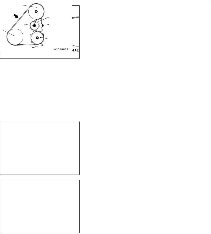
ON-VEHICLE SERVICE
DRIVE BELT TENSION CHECK AND
ADJUSTMENT
ALTERNATOR DRIVE BELT TENSION CHECK
Check the drive belt tension in the following procedure.
Standard value:
Vibration frequency Hz |
177 - 232 |
|
|
Tension N |
343 - 588 |
|
|
Deflection (Reference value) mm |
6.7 - 9.8 |
|
|

ENGINE <4G6-MPI> - On-vehicle Service |
11C-7 |
|
|
|
15_ |
15_ |
10 - 20 mm |
|
|
||
|
|
|
|
|
|
|
Water pump |
|
|
|
pulley |
MB991668 |
|
|
Crankshaft |
(Micro- |
|
|
|
phone) |
|
|
pulley |
Alternator pulley
Belt tension gauge
Water pump pulley
Crankshaft pulley
Alternator pulley
98 N
Water pump pulley
Crankshaft pulley
Alternator pulley
<When using the MUT-II>
1.Connect the special tool (belt tension meter set) to the MUT-II.
2.Connect the MUT-II to the diagnosis connector.
3.Turn the ignition switch to ON and select “Belt Tension Measurement” from the menu screen.
4.Hold the microphone to the middle of the drive belt between the pulleys (at the place indicated by the arrow), about 10 - 20 mm away from the rear surface of the belt and so that it is perpendicular to the belt (within an angle of ± 15_).
5.Gently tap the middle of the belt between the pulleys (the place indicated by the arrow) with your finger as shown in the illustration, and check that the vibration frequency of the belt is within the standard value.
Caution
(1)The temperature of the surface of the belt should be as close as possible to normal temperature.
(2)Do not let any contaminants such as water or oil get onto the microphone.
(3)If strong gusts of wind blow against the microphone or if there are any loud sources of noise nearby, the values measured by the microphone may not correspond to actual values.
(4)If the microphone is touching the belt while the measurement is being made, the values measured by the microphone may not correspond to actual values.
(5)Do not take the measurement while the vehicle’s engine is running.
<When using a tension gauge>
Use a belt tension gauge to check that the belt tension is within the standard value.
<Belt deflection check>
Apply 98 N of force to the middle of the drive belt between the pulleys (at the place indicated by the arrow) and check that the amount of deflection is within the standard value.
11C-8 |
ENGINE <4G6-MPI> - On-vehicle Service |
|
|
Adjusting bolt
Lock bolt
<Vehicles without A/C>
Oil pump pulley
98 N
AB
Crankshaft pulley
Tensioner pulley
<Vehicles with A/C>
Oil pump pulley |
|
|
98 N |
|
Tensioner |
|
|
|
|
|
pulley |
Crankshaft |
A |
B |
pulley |
|
|
A/C compressor pulley
ALTERNATOR DRIVE BELT TENSION ADJUSTMENT
1. |
Loosen the nut of the alternator pivot bolt. |
|||
2. |
Loosen the lock bolt. |
|
|
|
3. |
Use the adjusting bolt to adjust the belt tension and belt |
|||
|
|
deflection to the standard values. |
|
|
|
|
Standard value: |
|
|
|
|
|
|
|
|
|
Items |
When adjusting |
When replacing |
|
|
|
|
|
|
|
Vibration frequency Hz |
201 - 222 |
241 - 276 |
|
|
|
|
|
|
|
Tension N |
441 - 539 |
637 - 833 |
|
|
|
|
|
|
|
Deflection |
7.2 - 8.4 |
5.0 - 6.4 |
|
|
(Reference value) mm |
|
|
|
|
|
|
|
4. |
Tighten the nut of the alternator pivot bolt. |
|||
|
|
Tightening torque: 49 Nm |
|
|
5. |
Tighten the lock bolt. |
|
|
|
|
|
Tightening torque: 22 Nm |
|
|
6. |
Tighten the adjusting bolt. |
|
||
|
|
Tightening torque: 5 Nm |
|
|
POWER STEERING OIL PUMP AND AIR CONDITIONER COMPRESSOR DRIVE BELT TENSION CHECK AND ADJUSTMENT
1.Check if the belt tension is within the standard value using one of the methods below.
Standard value:
Items |
When |
When a |
When a new |
|
checked |
used belt is |
belt is |
|
|
installed |
installed |
|
|
|
|
Vibration |
108 - 132 |
114 - 126 |
137 - 157 |
frequency |
|
|
|
Hz |
|
|
|
|
|
|
|
Tension N |
392 - 588 |
441 - 539 |
637 - 834 |
|
|
|
|
Deflection |
11.7 - 15.3 |
12.5 - 14.3 |
8.8 - 11.0 |
(Reference |
|
|
|
value) mm |
|
|
|
|
|
|
|
<When measuring the vibration frequency>
With your finger tip lightly tap the centre of the belt between the pulleys in the location shown by the arrow in the illustration and then measure the belt vibration frequency.
NOTE
Refer to P.11C-7 for information regarding the vibration frequency measurement method using MUT-II.
<When measuring the tension>
Use a belt tension gauge to measure the belt tension.

ENGINE <4G6-MPI> - On-vehicle Service |
11C-9 |
|
|
<When measuring the deflection>
Apply 98 N of pressure against the location between the pulleys shown by the arrow in the illustration and then measure the deflection.
2.If the tension or deflection is outside the standard value, adjust by the following procedure.
(1)Loosen tensioner pulley fixing nut A.
(2)Adjust the amount of belt deflection using adjusting bolt B.
(3)Tighten fixing nut A.
Tightening torque: 25 Nm
(4)Check the belt deflection amount and tension, and readjust if necessary.
Caution
Check after turning the crankshaft once or more clockwise (right turn).
IGNITION TIMING CHECK
1.Before inspection, set the vehicle to the pre-inspection condition.
2.Connect the MUT-II to the diagnosis connector.
3.Set up a timing light.
4.Start the engine and run at idle.
5.Check that engine idle speed is within the standard value.
Standard value: 750 ± 100 r/min
6.Select No.17 of the MUT-II Actuator test.
7.Check that basic ignition timing is within the standard value.
Standard value: 5_ BTDC±3_
8.If the basic ignition timing is outside the standard value, inspect the MPI system while referring to GROUP 13A
-Troubleshooting.
9.Press the MUT-II clear key (Select a forced driving cancel mode) to release the Actuator test.
Caution
If the test is not cancelled, a forced driving will continue for 27 minutes. Driving under this condition may damage the engine.
10.Check that ignition timing is at the standard value.
Standard value: approx. 10_BTDC
NOTE
1.Ignition timing is variable within about ± 7_, even under normal operating.
2.And it is automatically further advanced by about 5_ from standard value at higher altitudes.

11C-10 |
ENGINE <4G6-MPI> - On-vehicle Service |
|
|
IDLE SPEED CHECK
1.Before inspection, set the vehicle to the pre-inspection condition.
2.Turn the ignition switch to “LOCK” (OFF) position and connect the MUT-II to the diagnosis connector.
3.Check the basic ignition timing.
Standard value: 5_ BTDC±3_
4.Run the engine at idle for 2 minutes.
5.Check the idle speed. Select item No. 22 and take a reading of the idle speed.
Standard value: 750 ± 100 r/min
NOTE
The idle speed is controlled automatically by the idle speed control (ISC) system.
6.If the idle speed is outside the standard value, inspect the MPI components by referring to GROUP 13A - Troubleshooting.
IDLE MIXTURE CHECK
1.Before inspection, set the vehicle to the pre-inspection condition.
2.Turn the ignition switch to “LOCK” (OFF) position and connect the MUT-II to the diagnosis connector.
3.Check that the basic ignition timing is within the standard value.
Standard value: 5_ BTDC±3_
4.Run the engine at 2,500 r/min for 2 minutes.
5.Set the CO, HC tester.
6.Check the CO contents and the HC contents at idle.
Standard value
CO contents: 0.5% or less
HC contents: 100 ppm or less
7.If there is a deviation from the standard value, check the following items:
D Diagnosis output
D Closed-loop control (When the closed-loop control is normal, the output signal of the oxygen sensor changes between 0 - 400 mV and 600 - 1,000 mV
at idle.)
DFuel pressure
DInjector
DIgnition coil, spark plug cable, spark plug
DLeak in the EGR system and in the EGR valve
DEvaporative emission control system
DCompression pressure

ENGINE <4G6-MPI> - On-vehicle Service |
11C-11 |
|
|
Compression gauge
NOTE
Replace the three way catalyst when the CO and HC contents are not within the standard value, even though the result of the inspection is normal on all items.
COMPRESSION PRESSURE CHECK
1.Before inspection, check that the engine oil, starter and battery are normal. In addition, set the vehicle to the pre-inspection condition.
2.Disconnect the spark plug cables.
3.Remove all of the spark plugs.
4.Disconnect the crank angle sensor connector.
NOTE
Doing this will prevent the engine-ECU <M/T> or engine-A/T-ECU <A/T> from carrying out ignition and fuel injection.
5.Cover the spark plug hole with a shop towel etc., and after the engine has been cranked, check that no foreign material is adhering to the shop towel.
Caution
1.Keep away from the spark plug hole when cranking.
2.If compression is measured with water, oil, fuel, etc., that has come from cracks inside the cylinder, these materials will become heated and will gush out from the spark plug hole, which is dangerous.
6.Set compression gauge to one of the spark plug holes.
7.Crank the engine with the throttle valve fully open and measure the compression pressure.
Standard value (at engine speed of 250 - 400 r/min): 1,400 kPa
Limit (at engine speed of 250 - 400 r/min): Min. 1,060 kPa
8.Measure the compression pressure for all the cylinders, and check that the pressure differences of the cylinders are below the limit.
Limit: Max. 100 kPa
9.If there is a cylinder with compression or a compression difference that is outside the limit, pour a small amount of engine oil through the spark plug hole, and repeat the operations in steps 7 and 8.
(1)If the compression increases after oil is added, the cause of the malfunction is a worn or damaged piston ring and/or cylinder inner surface.
11C-12 |
ENGINE <4G6-MPI> - On-vehicle Service |
|
|
Vacuum gauge
(2)If the compression does not rise after oil is added, the cause is a burnt or defective valve seat, or pressure is leaking from the gasket.
10.Connect the crank angle sensor connector.
11.Install the spark plugs and spark plug cables.
12.Use the MUT-II to erase the diagnosis codes.
NOTE
This will erase the diagnosis code resulting from the crank angle sensor connector being disconnected.
MANIFOLD VACUUM CHECK
1.Before inspection, set the vehicle to the pre-inspection condition.
2.Attach a three-way union to the vacuum hose between the fuel pressure regulator and the air intake plenum, and connect a vacuum gauge.
3.Start the engine and check that idle speed is within standard value. Then read off the vacuum gauge.
Limit: Min. 69 kPa
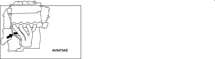
LASH ADJUSTER CHECK
If an abnormal noise (knocking) that seems to be coming from the lash adjuster is heard after starting the engine and does not stop, carry out the following check.
NOTE
(1)The abnormal noise which is caused by a problem with the lash adjusters is generated after the engine is started, and will vary according to the engine speed. However, this noise is not related to the actual engine load.
Because of this, if the noise does not occur immediately after the engine is started, if it does not change in accordance with the engine speed, or if it changes in accordance with the engine load, the source of the noise is not the lash adjusters.
(2)If there is a problem with the lash adjusters, the noise will almost never disappear, even if the engine has been run at idle to let it warm up.
The only case where the noise might disappear is if the oil in the engine has not been looked after properly and oil sludge has caused the lash adjusters to stick.
1.Start the engine.
2.Check that the noise occurs immediately after the engine is started, and that the noise changes in accordance with changes in the engine speed.
If the noise does not occur immediately after the engine is started, or if it does not change in accordance with the engine speed, the problem is not being caused by the lash adjusters, so check for some other cause of the problem. Moreover, if the noise does not change in accordance with the engine speed, the cause of the problem is probably not with the engine. (In these cases, the lash adjusters are normal.)

ENGINE <4G6-MPI> - On-vehicle Service |
11C-13 |
|
|
3.While the engine is idling, check that the noise level does not change when the engine load is varied (for example, by shifting from N ® D).
If the noise level changes, the cause of the noise is probably parts striking because of worn crankshaft bearings or connecting rod bearings. (In such cases, the lash adjusters are normal.)
4.After the engine has warmed up, run it at idle and check if any noise can be heard.
If the noise has become smaller or disappeared, oil sludge could make the lash adjusters stick. Clean the lash adjusters. (Refer to the Engine Workshop Manual.) If not improved, go to step 5.
5.Bleed air from the lash adjusters.
6.If the noise has not disappeared even after the air bleeding, clean the lash adjusters. (Refer to the Engine Workshop Manual.)
<LASH ADJUSTER AIR BLEEDING>
NOTE
(1)If the vehicle is parked on a slope for a long period of time, the amount of oil inside the lash adjuster will decrease, and air may get into the high pressure chamber when starting the engine.
(2)After parking the vehicle for long periods, the oil drains out of the oil passage, and it takes time for the oil to be supplied to the lash adjuster, so air can get into the high pressure chamber.
(3)If either of the above situations occur, the abnormal noise can be eliminated by bleeding the air from inside the lash adjusters.
|
1. Check the engine oil and replenish or replace the oil |
|
|
||
|
if necessary. |
|
|
NOTE |
|
|
(1) |
If there is a only small amount of oil, air will be drawn |
|
|
in through the oil screen and will get into the oil |
|
|
passage. |
|
(2) |
If the amount of oil is greater than normal, then the |
Good |
|
oil will being mixed by the crankshaft and a large |
|
amount of air may get mixed into the oil. |
|
|
(3) |
If the oil is degenerated, air and oil will not separate |
|
|
easily in oil, and the amount of air mixed into the |
|
|
|
|
|
oil will increase. |

11C-14 |
ENGINE <4G6-MPI> - On-vehicle Service |
|
|
Highpressure chamber
Drive pattern for air bleeding
|
Gradually open the |
|
|
Close the throttle |
|
throttle valve. |
|
|
valve. |
|
|
|
|
|
Approx. |
|
|
|
|
|
|
|
|
|
3,000 r/min |
|
|
|
|
Idle speed |
|
|
|
|
15 |
15 |
|
||
|
seconds |
seconds |
||
Once
(4)If the air which has been mixed in with the oil due to any of the above reasons gets into the high pressure chamber of the lash adjuster, the air inside the high pressure chamber will be compressed when the valve is open and the lash adjuster will over-compress, resulting in abnormal noise when the valve closes. This is the same effect as if the valve clearance is adjusted to be too large by mistake. If the air inside the lash adjusters is then released, the operation of the lash adjusters will return to normal.
2.Run the engine at idle for 1 - 3 minutes to let it warm up.
3.With no load on the engine, repeat the drive pattern shown in the illustration at left and check if the abnormal noise disappears. (The noise should normally disappear after 10 - 30 repetitions, but if there is no change in the noise level after 30 repetitions or more, the problem is probably not due to air inside the lash adjusters.)
4.After the noise has disappeared, repeat the drive pattern shown in the illustration at left a further 5 times.
5.Run the engine at idle for 1 - 3 minutes and check that the noise has disappeared.

|
ENGINE <4G6-MPI> - Crankshaft Pulley |
11C-15 |
|||
|
|
|
|
|
|
CRANKSHAFT PULLEY |
|
|
|
|
|
REMOVAL AND INSTALLATION |
|
|
|
|
|
|
|
|
|
|
|
|
Pre-removal Operation |
|
Post-installation Operation |
|
|
|
D Under Cover Removal |
|
D Drive Belt Tension Adjustment (Refer to P.11C-6.) |
|
|
|
|
|
D Under Cover Installation |
|
|
|
|
|
|
|
|
2
3
25 Nm
1
Removal steps |
|
|
1. Drive belt (Power steering and |
2. |
Drive belt (Alternator) |
A/C) |
3. |
Crankshaft pulley |

11C-16 ENGINE <4G6-MPI> - Camshaft and Camshaft Oil Seal
CAMSHAFT AND CAMSHAFT OIL SEAL
REMOVAL AND INSTALLATION
Pre-removal and Post-installation Operation
DAir Cleaner Removal and Installation
DTiming Belt Removal and Installation (Refer to P.11C-27.)
10 Nm
1
14 Nm |
4 |
22 Nm
3 10  12
12
6
7
13
Removal steps
1.Control harness connection
2.Spark plug cable and ignition coil
3.PCV hose connection
4.Breather hose
5.Rocker cover
6.Camshaft position sensor support
7.Camshaft position sensing cylinder AA" "CA 8. Camshaft sprocket
(f 3 ± 1 mm)
2 |
|
|
|
6 |
|
|
|
|
|
|
|
|
|
|
|
|
|
|
|
|
|
|
|
5 |
|
|
|
|
|
|
|
|
|
|
|
3.4 Nm |
|
|
|
|
|
|
|
|
|||
|
|
|
|
|
|
|
|
|
|
||
|
|
|
|
|
|
|
|
|
|
|
|
|
|
|
Sealant: |
||||||||
|
|
|
MITSUBISHI GENUINE PART |
||||||||
|
|
|
MD970389 or equivalent |
||||||||
11 |
|
|
|
|
|
|
|
|
|
|
|
|
|
|
|
|
|
|
|
|
|
||
|
|
|
|
|
|
|
|
|
|
||
|
|
|
|
|
Lip section |
|
|
|
|||
|
|
|
|
|
|
|
|
|
|
||
|
28 - 34 Nm |
|
9 |
|
|
|
|
|
|
||
|
|
|
|
|
|
|
|
||||
|
|
|
|
|
|
|
|
|
|
|
|
|
|
|
|
|
|
|
|
|
|
||
8 |
|
|
|
|
Cam section |
|
|
||||
|
|
|
|
and journal |
|
|
|
||||
|
|
|
|
|
|
section |
|
|
|
||
9 |
|
|
|
|
13 |
|
|
|
|
|
|
|
|
|
|
|
|
|
|
|
|
|
|
|
88 Nm |
|
|
|
|
|
|
|
|
||
|
|
Engine oil |
|
|
|||||||
|
|
|
|
|
|
|
|||||
|
|
|
|
|
|
|
|
|
|
|
|
"BA 9. |
Camshaft oil seal |
10. |
Spark plug guide oil seal |
AB" "AA 11. |
Rocker arm and shaft assembly |
AB" "AA 12. |
(intake side) |
Rocker arm and shaft assembly |
|
|
(exhaust side) |
13. |
Camshaft |

ENGINE <4G6-MPI> - Camshaft and Camshaft Oil Seal |
11C-17 |
|
|
MB990767
MD998719 or
MD998754
MD998443
REMOVAL SERVICE POINTS
AA" CAMSHAFT SPROCKET REMOVAL
AB" ROCKER ARM AND SHAFT ASSEMBLY REMOVAL
Before removing the rocker arm and shaft assembly, install the special tools as shown in the illustration so that the lash adjusters will not fall out.
INSTALLATION SERVICE POINTS
"AA ROCKER ARM AND SHAFT ASSEMBLY INSTALLATION
1.Temporarily tighten the rocker shaft with the bolt so that all rocker arms on the inlet valve side do not push the valves.
2.Fit the rocker shaft spring from the above and position it so that it is right angles to the plug guide.
NOTE
Install the rocker shaft spring before installing the rocker arm and rocker arm shaft on the exhaust side.
3.Remove the special tool for fixing the lash adjuster.
4.Confirm that the rocker shaft notch is in the direction shown in the diagram.
11C-18 ENGINE <4G6-MPI> - Camshaft and Camshaft Oil Seal
"BA CAMSHAFT OIL SEAL INSTALLATION
1.Apply engine oil to the camshaft oil seal lip.
2.Use the special tool to press-fit the camshaft oil seal.
MD998713
"CA CAMSHAFT SPROCKET INSTALLATION
Use the special tool to stop the camshaft sprocket from turning in the same way as was done during removal, and then tighten the bolts to the specified torque.

|
ENGINE <4G6-MPI> - Oil Pan |
11C-19 |
||
|
|
|
|
|
OIL PAN |
|
|
|
|
REMOVAL AND INSTALLATION |
|
|
|
|
|
|
|
|
|
|
Pre-removal and Post-installation Operation |
|
|
|
|
D Under Cover Removal and Installation |
D Oil Level Gauge Removal and Installation |
|
|
|
D Engine Oil Draining and Supplying |
D Front Exhaust Pipe Removal and Installation |
|
|
|
|
|
|
|
|
5 |
|
|
|
|
|
|
f 4 ± 1 mm |
|
|
39 Nm |
5 |
|
||
|
|
|
|
|
|||
Groove |
Bolt |
|
2 |
|
|
|
|
|
|
|
|
|
|||
|
|
|
|
|
|
||
hole |
|
|
|
|
|
|
|
|
|
|
|
|
|
|
|
|
|
|
1 |
|
|
|
|
|
|
|
|
|
|
|
|
Sealant: |
|
|
|
|
|
|
|
MITSUBISHI GENUINE PART |
|
|
|
|
|
4 |
|
MD970389 or equivalent |
|
|
|
|
|
||
|
|
|
|
|
|
||
|
|
9 Nm |
6 |
|
|
|
|
|
|
|
|
|
|
||
|
|
|
3 |
|
|
|
|
|
|
|
|
|
9 Nm |
|
9 Nm |
|
|
|
|
|
|
44 Nm |
|
|
|
|
|
|
|
|
|
Removal steps |
|
|
|
|
|
||
1. Drain plug |
|
|
|
4. Bell housing cover |
|
||
"AA 2. Drain plug gasket |
AA" |
5. Oil pan |
|
||||
3. Harness connector |
|
|
|
6. Oil level sensor |
|
||
|
|
REMOVAL SERVICE POINT |
MD998727 |
MD998727 |
|
|
|
AA" OIL PAN REMOVAL |
|
|
After removing the oil pan mounting bolts, remove the oil |
|
|
pan with the special tool and a brass bar. |
|
|
Caution |
|
|
Perform this slowly to avoid deformation of the oil pan |
|
|
flange. |
|
|
|
11C-20 |
ENGINE <4G6-MPI> - Oil Pan |
|
|
|
|
|
|
INSTALLATION SERVICE POINT |
|
|
|
|
|
"AA DRAIN PLUG GASKET INSTALLATION |
|
Oil pan side |
Install the drain plug gasket in the direction so that it faces |
|
as shown in the illustration. |
|
|
|
|
Drain plug |
|
|
gasket |
|
|
|
|
|

|
|
|
|
|
|
|
ENGINE <4G6-MPI> - Crankshaft Oil Seal |
|
11C-21 |
||||||||||||||||||||
|
|
|
|
|
|
|
|
|
|
|
|
|
|
|
|
|
|
|
|
|
|
|
|
|
|
|
|||
CRANKSHAFT OIL SEAL |
|
|
|
|
|
|
|
|
|
|
|
|
|
|
|
|
|||||||||||||
REMOVAL AND INSTALLATION |
|
|
|
|
|
|
|
|
|
|
|
|
|
|
|
|
|||||||||||||
|
|
|
|
|
|
|
|
|
|
|
|
|
|
|
|
|
|
|
|
|
|
|
|
|
|
|
|
|
|
|
|
|
127 - 137 Nm |
7 |
|
|
<M/T> |
|
|
|
|
|
|
|
|
|
|
|
|
|
|
|
|
||||||
|
|
|
|
|
|
|
|
|
|
|
|
|
|
|
|
|
|
|
|
|
|
|
|
|
|||||
|
|
8 |
|
|
|
|
|
9 |
|
|
|
|
|
|
|
|
|
|
|
|
|
||||||||
|
|
|
|
|
|
|
|
|
|
|
|
|
|
|
|
|
|
|
|
|
|
|
|
|
|
||||
|
|
|
|
|
|
|
|
|
|
|
|
|
|
11 |
|
|
|
|
|
|
|
|
|
|
|
|
|||
|
|
|
|
|
127 - 137 Nm |
|
|
|
|
12 |
|
|
|
|
|
|
|
|
|
|
|
||||||||
|
|
|
|
|
|
|
|
|
|
|
|
|
|
|
|
|
|
|
|
||||||||||
|
|
|
|
|
|
|
|
|
|
|
|
|
|
|
|
|
|
|
|
|
|||||||||
|
|
|
|
|
|
|
|
|
|
|
|
|
|
|
|
|
|
|
|
|
|
|
|
|
|
|
|
|
|
|
|
|
|
|
|
|
|
|
|
<A/T> |
|
|
|
|
|
|
|
|
|
|
|
|
|
|
|
|
|||
6 |
|
|
|
|
|
|
|
|
|
|
|
|
|
|
|
|
|
|
|
|
|
|
2 |
|
|
|
|||
|
|
|
|
|
|
|
|
|
|
|
|
|
|
|
|
|
|
|
|
|
|
|
|
|
|||||
|
|
|
|
|
|
|
|
|
|
|
|
|
|
|
|
|
|
|
|
|
|
|
|
|
|
|
|
|
|
|
|
|
|
|
|
8 |
|
|
|
|
|
|
|
|
|
|
|
|
|
|
|
|
|
|
|
4 |
|
|
|
|
|
|
|
|
|
|
|
|
|
|
|
|
|
|
|
|
|
|
|
|
|
|
|
|
|
|
|
|
|
|
|
|
|
|
|
|
|
10 |
|
|
|
|
|
|
|
|
|
|
|
|
|
|
|
1 |
|
|
|||
|
|
|
|
|
|
|
|
|
|
|
|
|
|
|
|
|
|
|
|
|
|
|
|
|
|
|
|
||
|
|
|
|
|
|
|
|
|
|
|
|
|
|
|
|
|
|
|
|
|
|
|
|
|
|
|
|
|
|
|
|
|
<M/T> |
|
|
|
|
|
|
|
<A/T> |
|
|
|
|
|
|
|
|
5 |
3 |
|
|
|
|
|
|
||
|
|
|
|
|
|
|
|
|
|
|
|
|
|
|
|
|
|
|
|
|
|
|
|
|
|
|
|
||
|
|
|
|
|
|
|
|
|
|
|
|
|
|
|
|
|
|
|
|
|
|
|
|
|
|
|
|
||
|
|
|
|
|
|
|
|
|
|
|
|
|
|
|
|
|
|
|
|
|
|
|
|
|
|
|
|
|
|
|
|
|
|
|
|
|
Crankshaft |
|
|
|
|
Crankshaft |
|
|
|
|
|
|
|
|
|
|
|
||||||
|
|
|
|
|
|
|
|
|
|
|
|
|
|
|
|
|
|
|
|
|
|
|
|
|
|
|
|
|
|
|
|
|
|
|
|
|
|
|
|
|
|
|
|
|
|
|
|
|
|
|
|
|
|
|
|
|
|
|
|
|
|
|
|
|
|
|
|
|
|
|
|
|
|
|
|
|
|
|
|
|
|
|
|
|
|
|
|
|
|
|
|
|
|
|
|
|
|
|
|
|
|
(Engine oil: |
|
|
|
|
|
12 |
|
|
|
5 |
|
|
|
||||
|
|
|
|
|
|
|
|
|
|
|
|
bolt washer |
|
|
|
|
|
|
|
|
|
|
|
||||||
|
|
(Engine oil: |
|
|
|
|
|
|
|
surface) |
|
|
|
|
|
|
|
|
|
|
|
|
|
|
|
|
|||
|
|
bolt wash- |
|
|
|
|
|
|
|
|
|
|
|
|
|
|
|
|
|
|
|
|
|
|
|
|
|
||
|
|
|
|
|
|
|
|
|
|
|
|
|
|
|
|
|
|
|
|
|
|
|
|
|
|
|
|||
|
|
er surface) |
|
|
|
|
|
|
|
|
|
|
|
|
|
|
|
|
|
|
|
|
|
|
|
|
|
||
|
|
|
|
|
|
|
|
|
|
|
|
|
|
|
|
|
|
|
|
|
|
|
|
|
|
|
|
|
|
|
|
|
|
|
|
|
|
|
|
|
|
|
|
|
|
|
|
|
|
|
|
|
|
|
|
|
|
||
|
9 |
|
|
|
|
|
|
|
|
|
|
|
|
|
|
|
|
|
|
|
|
|
|
|
Lip section |
|
|||
|
|
|
|
|
|
|
|
|
|
|
|
|
|
|
|
|
|
|
|
Lip section |
|
|
|||||||
|
|
|
|
|
|
|
|
|
|
|
|
|
|
10 |
|
|
|
|
|
|
|
|
|
|
|
|
|||
|
|
|
|
|
|
|
|
|
|
|
|
|
|
|
|
|
|
|
|
|
|
|
|
||||||
|
Sealant: 3M Stud locking 4170 or equivalent |
|
|
|
Engine oil |
|
|
|
|
|
|
|
|||||||||||||||||
|
|
|
|
|
|
|
|
|
|
|
|
|
|
|
|
|
|
|
|
|
|
|
|
||||||
|
|
|
Crankshaft front oil seal removal |
|
|
|
|
Crankshaft rear oil seal removal |
|||||||||||||||||||||
|
|
|
steps |
|
|
|
|
|
|
|
|
|
|
|
|
|
|
|
|
steps |
|
|
|
|
|||||
|
|
|
D |
Timing belt (Refer to P.11C-27.) |
AA" |
D |
Oil pan (Refer to P.11C-19.) |
||||||||||||||||||||||
|
|
|
D Timing belt B (Refer to P.11C-31.) |
D Transmission assembly |
|||||||||||||||||||||||||
|
|
|
D |
Crank angle sensor |
|
|
|
|
|
|
|
|
D |
Clutch cover and disc <M/T> |
|||||||||||||||
|
|
|
|
|
(Refer to GROUP 16.) |
|
|
|
|
|
|
|
|
6. Crankshaft bushing <A/T> |
|||||||||||||||
|
|
|
1. Crankshaft sprocket |
|
|
|
|
AB" "BA 7. Plate <M/T> |
|
|
|
|
|||||||||||||||||
|
|
|
2. Flange |
|
|
|
|
|
|
|
|
|
|
|
|
AB" "BA 8. Adapter plate |
|||||||||||||
|
|
|
3. Crankshaft sprocket B |
|
|
|
|
AB" "BA 9. Flywheel <M/T> |
|||||||||||||||||||||
|
|
|
4. Key |
|
|
|
|
|
|
|
|
|
|
|
|
AB" "BA 10. Drive plate <A/T> |
|||||||||||||
|
|
"CA 5. Crankshaft front oil seal |
|
|
|
|
AB" "BA 11. Adapter plate <M/T> |
||||||||||||||||||||||
"AA 12. Crankshaft rear oil seal
 Loading...