


FOREWORD
This service manual describes the specifications as well as the maintenance and adjustment procedures for Mitsubishi diesel engines. This manual also includes the detailed information on basic and special tools as the need arises.
The Mitsubishi diesel engines can offer highly efficient and reliable performance for many years to come, which, however, only can be achieved through the proper handling and the periodical inspection/maintenance work exercised in according to the procedures of disassembly, inspection/adjustment and reassembly described in this manual.
Before attempting any work on your engine, thoroughly read this manual to familiarize with the engine and the required procedures of the work.
All information contained in this manual is based on the engine produced at the time of publication and is subject to change as the engine improved without notice.
Pub. No. 99619-12140

HOW TO USE THIS MANUAL
This Service Manual describes the specifications of Mitsubishi diesel engines (land and standard applications) and relevant service standards, as well as the procedures for servicing the engines such as for disassembly, inspection, repair and reassembly. This manual is divided into Groups. Each Group covers a specific area of the engine.
The fuel injection pump, the governor and the turbocharger are handled in a separate manual.
Major contents of Groups are listed on the “General Contents” page. Detailed contents of each Group are listed on the first page of that Group.
For information on the operations and recommended inspection/maintenance schedule of forklift trucks, please refer to the operator’s manual for the forklift truck. For information on components/parts and spares ordering procedures, refer to the parts catalogue. For information on structures and functions, refer to appropriate training materials.
1. Notes on descriptions
(1)Parts shown in Figures as well as in the text are numbered in the order of disassembly.
(2)Inspecting points during disassembly are shown in the Disassembly figures by enclosing in the box.
(3)Service standards for inspection and repair are listed on the appropriate pages of this manual where the relevant descriptions are made. Also, a comprehensive listing of service standards is provided in Group 1.
(4)Parts reassembly sequence is provided below the Figure of that reassembly in the form of → → → →.
(5)In this manual, the following marks are provided to draw the reader’s attention to the safety notes described under the marks.
 This indicates a dangerous situation which can highly likely result in death or serious injury unless avoided.
 This indicates a potentially dangerous situation which may possibly lead to death or serious injury unless avoided.
 This indicates a potentially dangerous situation which may cause minor to moderate injury unless avoided.
This indicates a potential danger in which property damage may result unless avoided.
Note: This stresses important points or provides useful tips on engine operations and service.
(6)Wherever hardware tightening requires the application of engine oil, “WET” is mentioned. If not mentioned, tighten the hardware “dry” (engine oil should not be applied).
2. Terms
Nominal value ······This is the nominal dimension of the part being measured.
Standard value ······This is the dimension of the individual part being measured, the clearance between the parts in question, or the standard performance in question. Standard values have been arranged within the range appropriate for the inspection being carried out, and are not necessarily the design values.
Limit ·····················Parts that have reached the limit value should be replaced or repaired whichever is appropriate.
3. Abbreviations and standards
BTDC = Before Top Dead Center
ATDC = After Top Dead CenterBBDC = Before Bottom Dead CenterABDC = After Bottom Dead CenterTIR = Total Indicator ReadingAPI = American Petroleum Institute
ASTM = American Society for Testing and MaterialsJIS = Japan Industrial Standards
LLC = Long Life CoolantMIL = Military Specifications
MSDS = Material Safety Data SheetsSAE = Society of Automotive Engineers
4. Units
Values shown in this manual are based on SI units (International System of Units). The corresponding metric values are shown in ( ) immediately after the SI values. The SI to metric conversions are based on the following.
Pressure: 1 MPa = 10.197 kgf/cm2Torque: 1 N m = 0.10197 kgf mForce: 1 N = 0.10197 kgf
Horsepower: 1 kW = 1.341 HP = 1.3596 PSMeter of mercury: 1 kPa = 0.7 cmHg
Meter of water: 1 kPa = 10.197 cmH2O (cmAq)Rotational speed: 1 min-1 = 1 rpm

GENERAL CONTENTS
Group No. |
|
|
|
Group Name |
Page |
|
|
|
|
|
|
0 |
|
SAFETY CAUTIONS |
|
0 - 1 |
|
|
|
|
|
|
|
|
|
GENERAL |
|
1 - 1 |
|
|
|
|
|
|
|
|
|
SERVICE STANDARDS |
|
1 -11 |
|
1 |
|
|
|
|
|
|
TOOLS LIST |
|
1 -21 |
||
|
|
|
|
|
|
|
|
OVERHAUL TIMING |
|
1 -25 |
|
|
|
|
|
|
|
|
|
REMOVAL PREPARATIONS |
1 -29 |
||
|
|
|
|
|
|
|
|
|
|
ENGINE MAIN PARTS - DISASSEMBLY |
2 - 1 |
|
|
|
|
|
|
2 |
|
Engine Main Parts |
ENGINE MAIN PARTS - INSPECTION AND |
2 -17 |
|
|
CORRECTION |
||||
|
|
|
|
|
|
|
|
|
|
ENGINE MAIN PARTS - REASSEMBLY |
2 -33 |
|
|
|
|
|
|
|
|
|
|
FUEL SYSTEM - REMOVAL |
3 - 1 |
|
|
|
|
|
|
3 |
|
Fuel System |
FUEL SYSTEM - DISASSEMBLY, |
3 - 9 |
|
|
INSPECTION AND REASSEMBLY |
||||
|
|
|
|
|
|
|
|
|
|
FUEL SYSTEM - INSTALLATION |
3 -25 |
|
|
|
|
|
|
|
|
|
|
OIL SYSTEM - REMOVAL |
4 - 1 |
|
|
|
|
|
|
4 |
|
Lubrication System |
OIL SYSTEM - DISASSEMBLY, |
4 - 5 |
|
|
INSPECTION AND REASSEMBLY |
||||
|
|
|
|
|
|
|
|
|
|
OIL SYSTEM - INSTALLATION |
4 - 9 |
|
|
|
|
|
|
|
|
|
|
COOLING SYSTEM - REMOVAL |
5 - 1 |
|
|
|
|
|
|
5 |
|
Cooling System |
COOLING SYSTEM - DISASSEMBLY, |
5 - 5 |
|
|
INSPECTION AND REASSEMBLY |
||||
|
|
|
|
|
|
|
|
|
|
COOLING SYSTEM - INSTALLATION |
5 - 9 |
|
|
|
|
|
|
|
|
|
|
INLET AND EXHAUST SYSTEMS - |
6 - 1 |
|
|
|
|
REMOVAL |
|
|
|
|
|
|
|
6 |
|
Inlet and Exhaust |
INLET AND EXHAUST SYSTEMS - |
|
|
|
DISASSEMBLY, INSPECTION AND |
6 - 5 |
|||
|
Systems |
||||
|
|
REASSEMBLY |
|
||
|
|
|
|
|
|
|
|
|
|
INLET AND EXHAUST SYSTEMS - |
6 - 7 |
|
|
|
|
INSTALLATION |
|
|
|
|
|
|
|
|
|
|
|
ELECTRICAL SYSTEM - REMOVAL |
7 - 1 |
|
|
|
|
|
|
7 |
|
Air starter System |
ELECTRICAL SYSTEM - DISASSEMBLY, |
7 - 7 |
|
|
INSPECTION AND REASSEMBLY |
||||
|
|
|
|
|
|
|
|
|
|
ELECTRICAL SYSTEM - INSTALLATION |
7 -25 |
|
|
|
|
|
|
|
|
Engine - |
ENGINE - INSPECTION / ADJUSTMENT |
8 - 1 |
|
8 |
|
Inspection/Adjustment, |
|
|
|
|
RUNNING-IN TRIAL |
8 -12 |
|||
|
Running-in Trial and |
||||
|
|
|
|
||
|
|
Performance Test |
PERFORMANCE TEST |
8 -13 |
|
|
|
|
|
|
|
9 |
|
Others |
DISASSEMBLY AND REASSEMBLY OF |
9 - 1 |
|
|
GENERAL PARTS |
||||
|
|
|
|
|
|
|
|
|
|
|
|
Supplement |
|
|
|
|
|
|
|
|
|
||
Engine Inspection Sheets |
|
|
|||

SAFETY CAUTIONS
Warning Risk of fire and explosion ···0-2
●Never use open fire ······························0-2
●Keep things tidy around the engine ··········0-2
●Do not open the crankcase until it has
cooled down········································0-2
●Pay attention to fuel and oil leakage ·········0-2
●Use explosion-proof light························0-2
●Prevent short circuit ······························0-2
●Keep fire extinguisher and first-aid kit
at hand ··············································0-2
Warning Risk of entanglement into
the machine························0-3
●Keep guards on the rotating parts ············0-3
●Ensure safety in the surrounding area
when starting the engine ························0-3
●Keep away from rotating parts while the engine is running··································0-3
●Lockout/tagout ·····································0-3
●Always stop the engine before any inspection/service·································0-3
●Remove the turning gear after use ···········0-3
Warning Risk of burn ························0-4
●Do not touch the engine while it is
running or for a while after it is stopped ·····0-4
●Be careful when opening/closing the
radiator cap·········································0-4
●Replenish coolant only when
the coolant in the system is cold ··············0-4 ●Do not remove heat insulating material ·····0-4
Warning |
Exhaust gas is |
|
poisonous ···························0-4 |
●Ensure good ventilation while the |
|
engine is running··································0-4 |
|
Warning |
Hearing difficulty ·················0-4 |
●Wear ear protector································0-4 |
|
Warning |
Beware of falling engine ·····0-5 |
●Exercise caution when lifting the engine ····0-5
●Do not climb on the engine ·····················0-5
●Secure your foothold when carrying out service···············································0-5
Caution |
Use correct engine oil |
|
and LLC······························0-5 |
●Only use the specified fuel, engine oil
and coolant (LLC)·································0-5
●Handle LLC with care ····························0-5
●Lawful disposal of waste oil and
coolant···············································0-5
Caution |
Handling of battery··············0-6 |
●Handle the battery with care····················0-6 |
|
Caution |
How to handle |
|
emergencies ·······················0-6 |
●Engine overheat - Idle to cool down,
then stop the engine ·····························0-6
●Never restart the engine after a sudden
stop unless the cause is eliminated ··········0-6
●Stop the engine immediately upon oil
pressure drop ······································0-6
●Stop the engine immediately upon broken
fan belt···············································0-6
Caution Other considerations···········0-7
●Never alter or modify the engine ··············0-7
●Do not tamper with sealing ·····················0-7
●Daily and periodical inspection ················0-7
●Running-in period ·································0-7
●Warming up the engine ··························0-7
●Do not overload the engine ·····················0-7 ●Cooling down the engine························0-7
●Do not spill water onto the engine ··········· 0-7 ●Air cleaner maintenance precautions ········0-8 ●Observe safety rules at work sites ············0-8
●Wear appropriate clothes and protective gear···················································0-8
●Use appropriate tools when carrying out service
0-8
●Do not operate the starter continuously
●The battery switch must be kept ON while
the engine is running·····························0-8
●Precautions for road transport ·················0-8
SAFETY CAUTIONS
 Warning Risk of fire and explosion
●Never use open fire
When topping up or replacing fuel or engine oil, or cleaning parts in
wash oil, do not light a match, smoke or use any other open fire nearby. Doing these is extremely
dangerous as fuel and oils can catch fire. Completely wipe off any spilt fuel or engine oil as they are flammable and can be a fire hazard.
Store fuel and engine oil in a well-ventilated place. Firmly tighten the cap of the container.
●Pay attention to fuel and oil leakage
If leakage of fuel or oil is found, immediately take measures to stop it.
If leaking fuel or engine oil spills over the heated engine, fire may start, possibly leading to bodily injury or equipment damage.
●Use explosion-proof light
When checking fuel, engine oil, coolant, battery electrolyte, etc., use explosion-proof light. If ordinary light is used, these fluids may ignite and explode.
●Keep things tidy around the engine
Keep fuel, engine oil or any other flammables as well as explosives and other dangerous materials away from the engine. These materials can ignite and explode.
Keep the engine and the surrounding area free of waste, dirt, foreign matter, etc. These substances can be a fire hazard and invite overheating. In particular, ensure that the top of the battery is clean after service operations. Any waste left on the battery can cause short circuit.
Keep a running engine at least 1 m (3.3 ft.) away from the surrounding building or equipment to eliminate the risk of fire.
●Do not open the crankcase until it has cooled down
Do not attempt to open the crankcase side cover immediately after the engine is stopped. Wait at least 10 minutes until the engine has sufficiently cooled down.
If fresh air flows into the crankcase with the engine still hot, the remaining mist of oil may ignite and cause explosion.
●Prevent short circuit
Before inspecting or servicing the electrical/electronic system, disconnect the negative (-) cable from the battery terminal. Failure to observe this can cause the circuit to short, possibly starting a fire.
Loose terminals and damaged cables/wires can cause short circuit or even fire. Before carrying out service operation, check for loose or damaged components and repair or replace as required.
●Keep fire extinguisher and first-aid kit at hand
Keep a fire extinguisher at hand. Become familiar with the handling of the fire extinguisher.
Store a first-aid kit at the designated place. The kit should be kept fully
supplied so that it can serve the purpose at any time. Establish a set of actions to take in the event of fire or accident, including emergency contact numbers and means of communication.
0 - 2
SAFETY CAUTIONS
 Warning Risk of entanglement into the machine
●Keep guards on the rotating parts
Ensure that all guards are correctly installed over the rotating parts of
the engine. Damaged or loose guards should be repaired. Never attempt to remove the
camshaft cover, rocker cover or any other guards form rotating parts while the engine is running. Never leave exposed the drive belts and related couplers for auxiliaries and radiator. They should also be covered with guards.
Never remove these guards.
●Ensure safety in the surrounding area when starting the engine
Before starting the engine, ensure that no one is near the electric power generator and that no tools or foreign matter are left behind. Shout to people around you so that they will know you are starting the engine.
Never start the engine if a “Do not start” tag or any other similar message is posted on the starter switch, etc.
●Lockout/tagout
Perform lockout/tagout before carrying out any inspection/service.
Lockout/tagout is an ideal way of disconnecting the machine/equipment from the power source.
To lockout/tagout, remove the starter switch key, place the battery switch in the “OFF” position, and post a “Do not start” tag or other similar message on the starter switch.
The starter switch key should then be carried by the person who is going to perform inspection/service. If an air start system is used, close the air tank source valve and post a “Do not open” tag or other similar message.
●Always stop the engine before any inspection/service
Always stop the engine before performing any inspection/service. Never attempt to adjust belt tension while the engine is running. Otherwise, the operator runs a great risk of becoming entangled into the rotating parts and seriously injured.
●Keep away from rotating parts while the engine is running
Never stand near the rotating parts
while the engine is running. Do not place objects near the rotating parts that are likely to be caught by
these parts.
Should any part of human body (or tool) is caught by the rotating parts, dismemberment or other bodily injury will result.
●Remove the turning gear after use
Be sure to remove the turning gear after use. Never start the engine with the turning gear still installed or “engaged.” Otherwise, the engine will break and possibly someone may become injured.
0 - 3

SAFETY CAUTIONS
 Warning Risk of burn
●Do not touch the engine while it is running or for a while after it is
stopped
Never touch any part of the engine while it is running or for a while after
it is stopped. Otherwise, you may become burned.
Use a coolant temperature gauge to confirm that the engine has sufficiently cooled down before performing any inspection/service.
●Be careful when opening/closing the radiator cap
Never attempt to open the radiator cap while the engine is running and for a while after it is stopped. Stop the engine and wait until the coolant temperature has sufficiently dropped before opening the cap.
Slowly open the radiator cap to allow the internal pressure to escape. To prevent possible burn, wear thick rubber gloves or cover the cap with cloth to protect your hands from escaping vapor.
Tighten the radiator cap firmly.
Coolant is extremely hot while the engine is running or for a while after the engine is stopped. You may become burned by extremely hot vapor or coolant that will gush out if the radiator cap is opened.
●Replenish coolant only when the coolant in the system is cold
Do not replenish coolant for a while after the engine is stopped. Replenish coolant when the coolant in the system is sufficiently cold. Otherwise, you may become burned.
●Do not remove heat insulating material
The exhaust system components become extremely hot and therefore are covered with heat insulating material. Never remove the material. If the material needs to be removed at all for inspection/service, be sure to install it again after the operation.
 Warning Exhaust gas is poisonous
●Ensure good ventilation while the engine is running
If the engine is installed inside a building and the exhaust gas is directed outside through a duct, regularly check the duct for any leakage through the joints etc.
Do not run the engine in a building (warehouse, tunnel, etc.), confined space, or other poorly ventilated places if the engine is used for a portable generator. If the engine needs to be run in a building at all, ensure to direct the exhaust gas outside and provide sufficient ventilation. Also, take care not to direct the exhaust gas towards nearby plants or animals, if any.
Engine exhaust gas contains carbon monoxide and other substances that are harmful to humans. Running the engine in a poorly ventilated place can cause exhaust gas poisoning.
 Warning Hearing
difficulty
●Wear ear protector
Wear ear protector whenever entering the engine room. Otherwise, the combustion and mechanical noises may cause you to develop hearing difficulty.
0 - 4
SAFETY CAUTIONS
 Warning Beware of
falling engine
●Exercise caution when lifting the engine
The wire rope used to lift the engine should have enough strength to withstand the weight of the engine.
Attach the specified lifting gear onto the lifting hangers on the engine.
Ensure that the engine is well balanced when it is lifted by taking into account the engine’s center of gravity.
The angle of wire rope relative to the lifting hangers should be maintained at 60º or less. Above this, the hangers may be subjected to overload and break.
If direct contact between the wire rope and the engine is anticipated, protect them from damage by covering them with cloth or other soft material.
●Do not climb on the engine
Do not climb onto the engine, nor place a foot on the components on the side of the engine.
Otherwise, you may not only break the engine components but also fall and become injured.
Use a stool or a platform to work on the top of the engine. Be careful not to slip and fall.
●Secure your foothold when carrying out service
Use a stable stool or platform when working on the top of the engine or
other areas of the engine difficult to reach.
Do not use a rickety stool nor
substitute a box of parts. Otherwise, you may fall and become injured.
Do not leave anything on the stool.
 Caution Use correct engine oil and LLC
●Only use the specified fuel, engine oil and coolant (LLC)
Only use the fuel, engine oil and coolant (LLC) that are specified in this manual. Handle them with sufficient care.
Using fluids other than those specified in this manual or incorrect use of those specified in this manual will lead to many problems and may possibly cause failures.
Use the specified engine oil and LLC according to the instructions of MSDS (Material Safety Data Sheets) issued by and available from the manufacturers.
●Handle LLC with care
LLC is a strong alkali. Be careful not to drink it by mistake or allow it to contact your eyes.
Old coolant (containing LLC) that has been drained off is toxic. Do not dispose of it carelessly. Dispose of it in accordance with the applicable laws and regulations.
●Lawful disposal of waste oil and coolant
Do not dispose of waste oil or coolant carelessly. Doing so is harmful to the environment and is prohibited by law.
Harmful substances such as waste oil and coolant should be disposed of in a manner that complies with the applicable laws and regulations.
0 - 5
SAFETY CAUTIONS
 Caution Handling of
battery
●Handle the battery with care
Batteries emit hydrogen and oxygen gases, both of which are
flammable. Never use open fire or 

 generate sparks near the battery.
  Otherwise, these gases may ignite and explode.Do not use the battery if the electrolyte level has
dropped below the minimum line. Otherwise, the battery may explode.
Be careful not to inadvertently place a metal object such as tool between the battery terminals.
Always disconnect the negative (-) terminal first, then the positive (+) terminal, from the battery. Always connect the positive (+) terminal first, then the negative (-) terminal, to the battery.
Recharge the battery in a well ventilated place, with all battery plugs removed.
The battery terminals should have a positive connection. Loose terminals can generate sparks, possibly causing the battery to explode.
Before servicing or performing electric welding on the electrical/electronic system, position the battery switch in the “OPEN/OFF” position or disconnect the negative (-) terminal of the battery to isolate the electrical/electronic circuit.
The battery electrolyte contains dilute sulfuric acid. Incorrect handling may lead to loss of eyesight or burn. Never drink battery electrolyte.
Wear protective goggles and rubber gloves when maintaining the battery (replenishing, recharging, etc.).
If your skin or clothing has come into contact with battery electrolyte, immediately wash the affected area with plenty of water and then thoroughly clean with soap.
Should your eyes come into contact with battery electrolyte, loss of eyesight may result. Immediately wash your eyes with plenty of fresh water and seek medical attention immediately.
Should you inadvertently drink battery electrolyte, repeatedly gargle with plenty of water and then drink plenty of water. Seek medical attention immediately.
 Caution How to handle emergencies
●Engine overheat - Idle to cool down, then stop the engine
In the event of engine overheat, do not stop the engine immediately. Doing so may cause the coolant temperature to rise quickly and the engine may seize. Instead, run the engine at low idle for a while to cool it down. Then, stop the engine. Do not attempt to replenish coolant for a while after the engine is stopped. Otherwise, the cylinder head etc., which may still be hot, is cooled down rapidly and may break. Wait until the engine is sufficiently cold and then top up slowly.
●Never restart the engine after a sudden stop unless the cause is eliminated
If the engine has suddenly stopped with some alert signals, do not restart immediately. Otherwise, the engine may seriously become damaged. Locate and eliminate the cause before restarting.
●Stop the engine immediately upon oil pressure drop
If the oil pressure has dropped, immediately stop the engine. Otherwise, bearings etc. may seize. Inspect the oil system and components.
●Stop the engine immediately upon broken fan belt
If the fan belt has broken, immediately stop the engine. Otherwise, the engine will overheat. Also, coolant vapor will gush out from the reserve tank and radiator and you may get burned.
0 - 6

SAFETY CAUTIONS
 Caution Other considerations
●Never alter or modify the engine
Altering or modifying the engine in any way will nullify the warranty.
A modified engine may not only break but also lead to injury.
●Do not tamper with sealing
To help ensure trouble-free operation of the engine, the fuel control link has been sealed to achieve the correct fuel injection volume and engine speed. If the sealed setting is tampered with, the following will result and the correct functioning of the engine is no longer guaranteed.
Sliding and rotating parts will wear faster.Various parts will seize/become damaged.The engine will consume more fuel and oil.The governor and fuel injection volume go out of
balance, reducing the engine performance.
●Warming up the engine
Before starting work, warm up the engine by running it at low idle for 5 to 10 minutes.
Warming up the engine will not only smoothen the operation of various engine parts but also help extend its service life. It also helps maximize the performance and achieve economical running of the engine.
Do not warm up the engine longer than necessary. Doing so facilitates carbon deposit on the cylinders, possibly leading to poor combustion.
●Do not overload the engine
Do not continue to run the engine if it emits black smoke.
Overloaded running of the engine (accompanied by black smoke) not only consumes excessive fuel but also facilitates carbon deposit and thus shortens the service life of the engine.
●Daily and periodical inspection
Perform the daily and periodical inspection in accordance with the Operation and Maintenance Manual.
Failure to observe the instructions of the manual may lead to many problems, and the various engine parts may eventually fail, possibly causing a serious accident.
●Running-in period
A brand new engine requires a running-in period of 50 hours, during which never put the engine under severe load. Otherwise, the service life of the engine will be reduced.
●Cooling down the engine
Before stopping the engine, cool it down (by running it at low idle) for 5 to 6 minutes.
Stopping the engine suddenly while it is heavily loaded will result in some areas of the engine remaining extremely hot for a while, which is detrimental to the long service life of an engine.
While the engine is being run at low idle for cooling, check the engine for any problems.
●Do not spill water onto the engine
Ensure that no rainwater etc. enters into the engine from the exhaust or inlet manifold, or via any other routes.
Do not run the engine while at the same time washing it. Otherwise, cleaning fluid (water) may be sucked into the engine.
If the engine is started with water trapped in the combustion chambers, water hammering will result, causing the engine to fail and possibly leading to a serious accident.
0 - 7

SAFETY CAUTIONS
●Air cleaner maintenance precautions
Wear of engine parts is accelerated largely by the dust contained in the intake air. Worn engine parts will lead to various problems such as increased oil consumption, reduced power and poor starting. Air cleaner is effective in removing dust in the intake air. When maintaining the air cleaner, observe the following precautions.
Never attempt to service the air cleaner while the engine is running.
When removing the air cleaner, take care not to allow the dust trapped on the air cleaner to enter into the inlet port.
If the engine is equipped with the dust indicator, clean the air filter only when the indicator shows clogging. Unnecessary maintenance (removal/ installation of the filter element) runs the risk of allowing dust into the inlet port or damaging/ deforming the filter element.
●Observe safety rules at work sites
Whenever running or servicing the engine, always observe the relevant safety rules in place.
If you are not in good shape, do not operate the engine. Consult the site supervisor.
Poor physical conditions are accompanied by reduced attention. Do not operate the engine if you are not feeling well. Otherwise, you may incorrectly handle the engine and cause an accident.
When working jointly with other people on the same task, use signals to coordinate actions involved.
●Wear appropriate clothes and protective gear
Whenever appropriate, including when using compressed air, wear protective gear such as helmet, face mask, safety shoes, dust mask, goggles and gloves.
Working without appropriate protective gear may lead to serious injury.
●Use appropriate tools when carrying out service
When carrying out any service, use appropriate tools and in correct ways.
Damaged tools should be replaced with new ones.
●Do not operate the starter continuously
Do not operate the starter more than 10 seconds per starting attempt. If the engine fails to start at the first attempt, wait for at least 30 seconds before trying again.
Do not run the starter continuously if the engine will not start. Otherwise, the battery will go flat or the starter will seize.
●The battery switch must be kept ON while the engine is running
Do not turn off the battery switch while the engine is running.
Otherwise, the instruments will become inoperative and the diode or transistor of the alternator may deteriorate.
●Precautions for road transport
When transporting the engine on public roads, the weight, width and height of the electric power generator should be taken into account while observing the relevant laws regarding road traffic and haulage, and vehicle restrictions and requirements.
0 - 8

GENERAL
1.Overview ····························································································· 1 - 2
1.1Outline Drawing ··················································································· 1 - 2
1.2Fuel System Schematic ········································································ 1 - 4
1.3Oil System Schematic··········································································· 1 - 4
1.4Cooling System Schematic ···································································· 1 - 5
1.5Inlet / Exhaust System Schematic ··························································· 1 - 5
1.6Engine Serial Number··········································································· 1 - 6
1.7Engine Model and Application Codes ······················································ 1 - 6
2.Specifications ······················································································ 1 - 7
3.Disassembly / Reassembly Notes······················································· 1 - 9
3.1Disassembly ······················································································· 1 - 9
3.2Reassembly························································································ 1 - 9
GENERAL
1. Overview
1.1 Outline Drawing
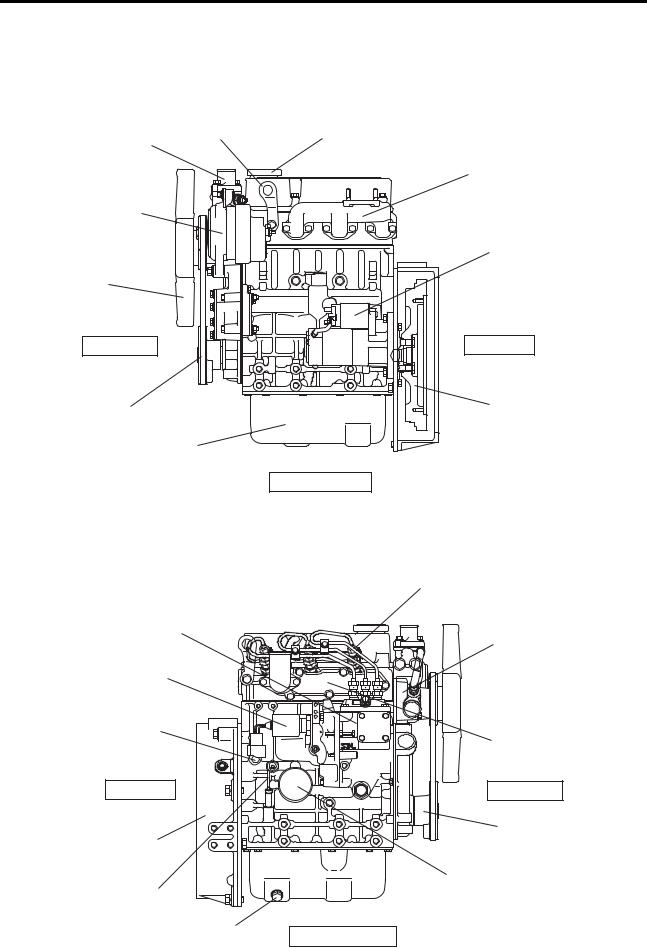
S3L, S3L2
Hanger |
Oil filler |
Thermostat |
|
Exhaust manifold
Alternator
Starter
Fan
Front end |
Rear end |
V belt |
Flywheel |
Oil pan |
|
|
Left-hand side |
|
Engine LH side view |
|
Fuel injection nozzle |
Fuel injection pump |
Water pump |
|
|
Stop solenoid |
|
Coolant drain plug |
|
|
Inlet cover |
Rear end |
Front end |
Flywheel housing |
Crankshaft pulley |
|
|
|
Oil filter |
Oil level gauge |
|
Oil drain plug
Right-hand side
Engine RH side view
1 - 2

GENERAL
S4L, S4L2
Hanger
Thermostat
Alternator
Fan
Front end
V belt
Oil pan
Fuel injection pump
Stop solenoid
Coolant drain plug
Rear end
Flywheel housing
Oil filter
Oil drain plug
Oil filler
Exhaust manifold
Starter
Rear end
Flywheel
Left-hand side
Engine LH side view
Fuel injection nozzle
Water pump
Inlet cover
Front end
Crankshaft pulley
Oil level gauge
Right-hand side
Engine RH side view
1 - 3
GENERAL
1.2 Fuel System Schematic
Fuel leak-off pipe |
Fuel injection pipe |
To fuel tank
Fuel injection nozzle
Fuel pump
 O
O
PE
 N
N
Fuel injection pump
From fuel tank |
Fuel filter |
Fuel system schematic
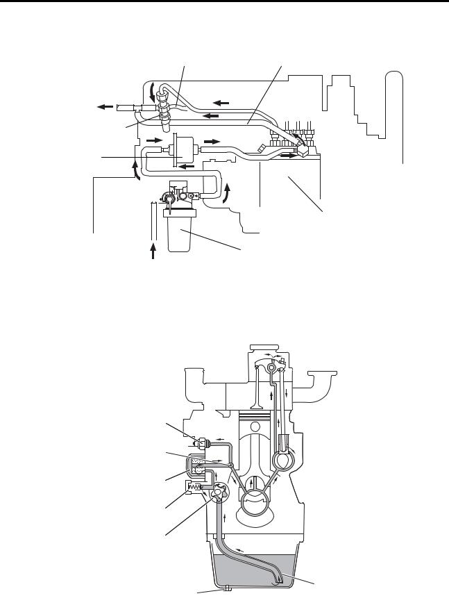
1.3 Oil System Schematic
Oil pressure switch
Oil main gallery
Oil filter
Relief valve
Oil pump
Oil strainer
Oil drain plug
Oil system schematic
1 - 4
GENERAL
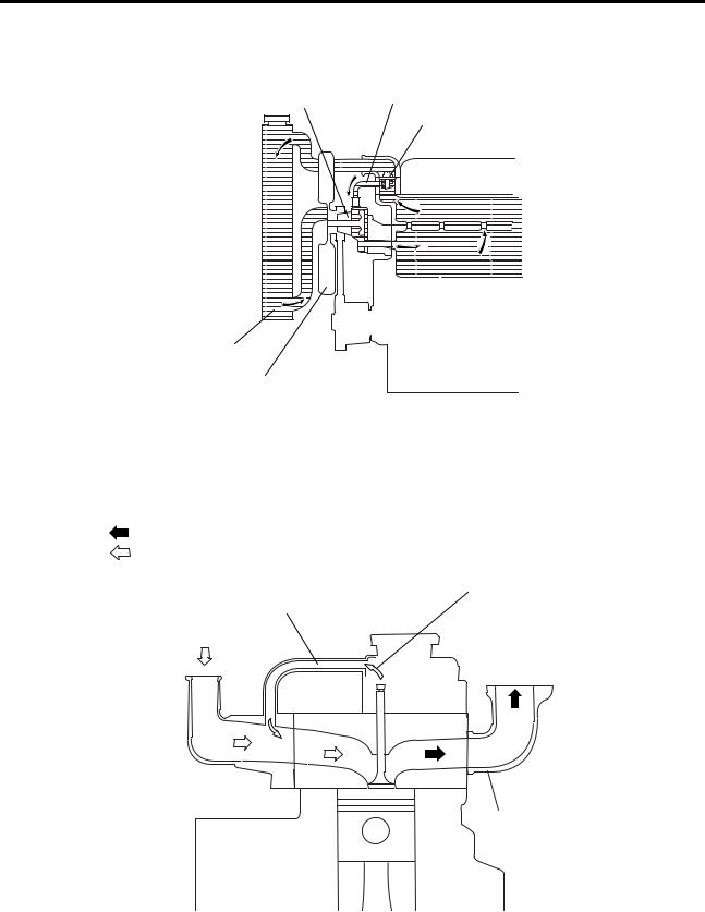
1.4 Cooling System Schematic
Water pump |
Water bypass valve |
|
Thermostat |
Radiator
Cooling fan
Cooling system schematic
1.5 Inlet / Exhaust System Schematic
Exhaust gas
Intake air
Air breather pipe
(positive crankcase Blow-by gas ventilation)
Intake air (from air cleaner)
Exhaust gas (to muffler)
Inlet cover 
Exhaust manifold
Inlet / exhaust system schematic
1 - 5
GENERAL
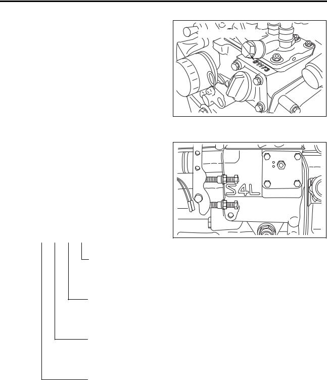
1.6Engine Serial Number
The engine serial number is stamped on the top face of the fuel injection pump bracket on the right-hand side of the cylinder block.
Engine serial number |
Engine serial number location
1.7 Engine Model and Application Codes
(1)The engine model code is embossed on the side of the fuel injection pump mount on the
right-hand side of the cylinder block.
(2) The engine model code consists of the following alphanumerical digits.
Model coding
(Example) S 4 L 2
Engine model code
Type
(2 = Type 2)
Series
[L = bore size 78 mm (3.07 in.)]
No. of cylinders (4 = 4 cylinders)
S = Sagamihara Machinery Works
1 - 6
|
|
|
|
|
|
|
|
|
|
|
|
GENERAL |
|
|
|
|
|
|
|
|
|
|
|
|
|
2. |
Specifications |
|
|
|
|
|
|
|
|
|
||
|
|
|
|
|
|
|
|
|
|
|
|
|
|
|
Engine Type |
|
|
S3L |
|
S3L2 |
|
S4L |
|
S4L2 |
|
|
|
Type |
|
|
|
Water- |
cooled; 4-stroke |
cycle; Diesel |
powered |
|||
|
|
No. of cylinders |
|
|
|
3 |
|
4 |
|
|||
|
|
Combustion |
|
|
|
|
|
Swirl chamber type |
|
|||
|
|
Valve mechanism |
|
|
|
|
Overhead valve type |
|
||||
|
|
Cylinder bore×stroke |
mm (in.) |
78×78.5 |
|
78×92 |
|
78×78.5 |
|
78×92 |
||
|
|
(3.07×3.09) |
(3.07×3.62) |
(3.07×3.09) |
(3.07×3.62) |
|||||||
|
<![if ! IE]> <![endif]>General |
Total displacement |
l (U.S. gal) |
1.125 |
|
1.318 |
|
1.500 |
|
1.758 |
||
|
(0.297) |
|
(0.348) |
|
(0.396) |
|
(0.464) |
|||||
|
|
|
|
|
||||||||
|
|
|
|
|
|
|
|
|
||||
|
|
Compression ratio |
|
|
|
|
22.0 |
: 1 |
|
|
||
|
|
Fuel |
|
|
|
|
Diesel fuel (JIS K2204 Special 1 - 3) |
|
||||
|
|
Firing order |
|
|
|
|
1-3-2 |
|
1-3-4-2 |
|||
|
|
Direction of rotation |
|
|
Counterclockwise when viewed from the flywheel end |
|||||||
|
|
Dimensions |
Overall length |
mm (in.) |
536 (21.10) |
|
620 (24.40) |
|||||
|
|
Overall width |
mm (in.) |
433 (17.04) |
|
433 (17.04) |
||||||
|
|
|
Overall height |
mm (in.) |
572 (22.52) |
|
572 (22.52) |
|||||
|
|
Dry mass |
|
|
kg (lb) |
135 (297.6) |
|
155 (341.7) |
||||
|
<![if ! IE]> <![endif]>parts |
Piston ring |
No. of rings |
|
|
|
|
Compression |
ring :2 |
|
||
|
|
|
|
|
Oil ring (w/expander) : 1 |
|
||||||
|
|
|
|
|
|
|
|
|||||
|
|
|
|
|
|
|
|
|
||||
|
<![if ! IE]> <![endif]>main |
Valve |
Inlet valve |
|
Open |
|
|
BTDC 15° |
|
|||
|
|
Close |
|
|
ABDC 41° |
|
||||||
|
timing |
|
|
|
|
|
||||||
|
|
|
Open |
|
|
BBDC 54° |
|
|||||
|
<![if ! IE]> <![endif]>Engine |
(hot engine) |
Exhaust valve |
|
|
|
|
|||||
|
|
Close |
|
|
ATDC 10° |
|
||||||
|
|
|
|
|
|
|
||||||
|
|
|
|
|
|
|
|
|||||
|
|
Engine mounting |
|
|
|
|
4 mounts |
|
||||
|
|
Starting method |
|
|
|
|
|
Starter |
|
|||
|
|
|
Type |
|
|
|
|
Bosch M |
|
|||
|
|
|
Manufacturer |
|
|
|
|
DENSO |
|
|||
|
|
Injection |
Plunger |
mm (in.) |
|
|
φ5.5 (0.21) |
|
||||
|
|
diameter |
|
|
|
|||||||
|
|
pump |
|
|
|
|
|
|
|
|
|
|
|
|
MS retard |
|
|
|
|
|
8° |
|
|
||
|
|
|
|
|
|
|
|
|
|
|||
|
<![if ! IE]> <![endif]>system |
|
(crank angle) |
|
|
|
|
|
|
|
||
|
|
|
|
|
|
|
|
|
|
|
||
|
|
Cam lift |
mm(in.) |
|
15 (0.59) |
|
|
|||||
|
Governor |
Governing method |
|
|
Centrifugal fly-weight type |
|
||||||
|
<![if ! IE]> <![endif]>Fuel |
|
Type |
|
|
|
|
Throttle nozzle |
|
|||
|
Injection |
Manufacturer |
|
|
Bosch Automotive Systems Corporation |
|||||||
|
|
|
|
|||||||||
|
|
Spray angle |
mm (in.) |
|
|
|
15° |
|
|
|||
|
|
nozzle |
Opening |
|
MPa |
|
|
14.22 to 15.00 (145 to 153) |
|
|||
|
|
|
(kgf/cm2) |
|
|
|
||||||
|
|
|
pressure |
|
[psi] |
|
|
[2062 to 2176] |
|
|||
|
|
|
|
|
|
|
|
|
|
|
|
|
|
|
Fuel filter |
Type |
|
|
Paper-element cartridge; Separate type w/ cock |
||||||
|
|
Lubrication |
method |
|
|
Forced circulation (pressure feed by trochoid pump) |
||||||
|
|
Engine oil |
Grade |
|
|
|
|
CD Class (API Classification) |
|
|||
|
|
Capacity |
l (U.S. gal) |
3.7 (1.0) |
|
4.2 (1.1) |
|
5.4 (1.4) |
|
6.0 (1.6) |
||
|
<![if ! IE]> <![endif]>system |
|
(entire engine) |
|
|
|
||||||
|
Oil pump |
Type |
|
|
|
|
Gear |
pump |
|
|
||
|
Displacement |
l (U.S. gal) |
|
18 (4.8) |
|
|
||||||
|
<![if ! IE]> <![endif]>Oil |
|
|
|
/min |
|
|
|
|
|
|
|
|
|
Type |
|
|
|
|
Piston valve |
|
||||
|
|
Relief valve |
Opening |
|
MPa |
|
0.35±0.05 (3.6±0.5) |
|
|
|||
|
|
(kgf/cm2) |
|
|
|
|||||||
|
|
|
pressure |
|
[psi] |
|
[51±7] |
|
|
|||
|
|
|
|
|
|
|
|
|
|
|
|
|
|
|
Oil filter |
Type |
|
|
|
|
Paper element (spin-on type) |
|
|||
1 - 7
GENERAL
|
|
Engine Type |
|
|
|
S3L |
|
S3L2 |
|
S4L |
|
S4L2 |
|
|
|
Cooling method |
|
|
|
|
|
Water-cooled, |
forced circulation |
|
|||
|
|
Capacity (engine proper) |
l (U.S. gal) |
1.8 (0.5) |
|
2.5 (0.7) |
|||||||
|
<![if ! IE]> <![endif]>system |
Water pump |
Type |
|
|
|
|
|
Centrifugal |
pump |
|
||
|
Displacement |
l (U.S. gal) |
30 (8.0) up (@ 2000 min-1 engine speed) |
||||||||||
|
|
|
|
|
|
/min |
|
|
|
|
|
|
|
|
<![if ! IE]> <![endif]>Cooling |
Thermostat |
Type |
|
|
|
|
|
Wax |
|
|||
|
|
Opening |
|
|
(°) |
|
82±1.5 (179.6±2.7) |
|
|
||||
|
|
|
temperature |
|
|
|
|
|
|||||
|
|
|
|
|
|
|
|
|
|
|
|
|
|
|
|
Cooling fan |
Type |
|
|
|
|
|
Pusher suction (PP fan) |
|
|||
|
|
No. of blades / OD |
5 / 340 (13.39), 6 / 320 (12.6), 6 / 340 (13.39), |
||||||||||
|
|
|
|
|
mm (in.) |
6 / 360 (14.17), 6 / 380 (14.96), 7 / 380 (14.96) |
|||||||
|
<![if ! IE]> <![endif]>system |
|
|
|
|
|
|
|
|
|
|
|
|
|
<![if ! IE]> <![endif]>entl |
Air cleaner |
Type |
|
|
|
|
|
Paper element |
|
|||
|
<![if ! IE]> <![endif]>I |
|
|
|
|
|
|
|
|
|
|
|
|
|
|
|
|
|
|
|
|
|
|||||
|
|
Voltage - Polarity |
|
|
|
12 V - Θ ground, 24 V - Θ ground |
|||||||
|
|
|
Type |
|
|
|
M001T68281, M008T70471A, M008T81071A |
||||||
|
|
|
Manufacturer |
|
|
|
|
Mitsubishi Electric Corporation |
|
||||
|
|
|
Pinion |
|
|
|
|
|
Pinion shift (reduction) |
|
|||
|
|
Starter |
engagement |
|
|
|
|
|
|
||||
|
|
|
|
|
|
|
|
|
|
|
|
||
|
|
Output |
|
|
V-kW |
|
|
12 V-1.7, 12 V-2.0, 24 V-3.2 |
|
||||
|
|
|
|
|
|
|
|
||||||
|
|
|
No. of units |
|
|
|
|
|
|
1 |
|
|
|
|
|
|
Reduction ratio |
|
|
13 / 120 |
|
|
|||||
|
|
|
(pinion / ring gear) |
|
|
|
|||||||
|
|
|
|
|
|
|
|
|
|
||||
|
|
|
Type |
|
|
|
3-phase alternator w/ built-in IC regulator |
||||||
|
<![if ! IE]> <![endif]>system |
|
Manufacturer |
|
|
|
|
Mitsubishi Electric Corporation |
|
||||
|
|
rated voltage is |
min-1 |
5000 (@ 13.5 V, 47 A), 5000 (@ 27.0 V, 22 A) |
|||||||||
|
|
Alternator |
Output |
|
|
V-A |
|
12-50, 24-25 |
|
|
|||
|
<![if ! IE]> <![endif]>Electrical |
Speed at which |
|
|
|
|
|
|
|
|
|||
|
|
Type |
|
|
|
|
|
Sheathed plug |
|
||||
|
|
|
generated |
|
|
|
|
|
|
|
|
|
|
|
|
|
Regulated voltage |
V |
14.7±0.3 (12-50), 26.5±0.5 (24-25) |
||||||||
|
|
|
|
|
|
|
|
|
|
|
|||
|
|
Glow plug |
Rated voltage - |
V-A |
12 V plug |
|
24 V plug |
||||||
|
|
10.5-9.7 |
|
22.5-5 |
|||||||||
|
|
|
current |
|
|
|
|||||||
|
|
|
|
|
|
(30-second application) |
|
(25-second application) |
|||||
|
|
|
|
|
|
|
|
||||||
|
|
|
Operating |
|
|
V |
12 V-ETR |
|
12 V-ETS |
|
24 V-ETR |
|
24 V-ETS |
|
|
|
voltage |
|
|
8 or less |
|
10 to 15 |
|
16 or less |
|
20 to 30 |
|
|
|
|
|
|
|
|
|
|
|||||
|
|
|
Insulation resistance |
|
|
100 MΩ or more at DC500 V |
|
||||||
|
|
Stop |
(at ordinary temperature and humidity) |
||||||||||
|
|
|
|
|
|
||||||||
|
|
solenoid |
Stroke |
|
mm (in.) |
|
13.5±0.5 (0.53±0.01) |
|
|
||||
|
|
|
Working |
|
|
|
-40 to 120 |
|
-30 to 120 |
|
-40 to 120 |
|
-30 to 120 |
|
|
|
ambient |
|
|
(°) |
|
|
|
||||
|
|
|
|
|
(-40 to 248) |
|
(-22 to 248) |
|
(-40 to 248) |
|
(-22 to 248) |
||
|
|
|
temperature |
|
|
|
|
|
|
|
|
|
|
1 - 8

GENERAL
3. Disassembly / Reassembly Notes
This Service Manual specifies various procedures recommended by Mitsubishi Heavy Industries, Ltd. for servicing Mitsubishi diesel engines. These procedures include, wherever appropriate, required special tools and related safety precautions.
The instructions provided in this manual, however, cannot fully guarantee safety as potential risks beyond ordinary imagination are hidden everywhere.
When conduct any work, the following points should also be observed in addition to the instructions this manual.
3.1 Disassembly
(1)Use tools and equipment that are appropriate for the work being carried out.
(2)Whenever necessary, use workbenches to work on or sort parts out. Disassemble in accordance with the disassembly sequence given in the manual.
(3)As parts are disassembled, place them neatly in the order of removal to eliminate missing parts on reassembly.
(4)During disassembly, note the assembly marks. Remember to respect these marks on reassembly. Whenever appropriate, put additional assembly marks to aid reassembly.
(5)Before and during disassembly as well as during subsequent washing, carefully check for any abnormality or other fault which otherwise may likely remain unnoticed afterwards.
(6)Pay sufficient attention to ensure safety, especially when lifting or carrying heavy components and parts. (Use a jack or a chain block as required.)
3.2 Reassembly
(1)Parts excluding oil seals, O-rings, rubber sheets, etc. should be thoroughly washed in wash oil and completely dried using compressed air.
(2)Use appropriate tools and equipment.
(3)Use good-quality oil and grease. Never fail to apply oil, grease, sealant and adhesive to the relevant locations if so instructed in the manual.
1 - 9

GENERAL
(4)Tighten hardware to the specified torque, if provided in the manual. Be sure to use a torque wrench.
(5)Gaskets, packing and O-rings should be replaced with new parts unless specified otherwise.
1 - 10

SERVICE STANDARDS
1.Service Standards Table····································································· 1 -12
2.Tightening Torques Table···································································· 1 -16
2.1Major Bolts and Nuts ··········································································· 1 -16
2.2Standard Bolts and Nuts······································································· 1 -17
2.3Standard Eyebolts ··············································································· 1 -17
2.4Standard Union Nuts ··········································································· 1 -18
2.5Taper Bolts ························································································ 1 -18
3.Sealants List······················································································· 1 -19

SERVICE STANDARDS
1. Service Standards Table
Unit: mm (in.)
<![endif]>Group
<![if ! IE]><![endif]>Engine general
<![if ! IE]><![endif]>Engine main parts
|
|
|
Item |
|
|
|
Nominal |
Standard value |
Limit |
|
|
|
|
|
|
Remarks |
|
|
|
|
|
|
||||||||||||
|
|
|
|
|
|
value |
|
|
|
|
|
|
|
|
|
|
|
|
||||||||||||||||
|
|
|
|
|
|
|
|
|
|
|
|
|
|
|
|
|
|
|
|
|
|
|
|
|
|
|
|
|
|
|
|
|
|
|
Max. speed |
|
|
|
|
+30 |
|
-1 |
|
|
|
|
|
|
|
|
|
|
|
|
|
|
|
|
|
|
|
|
|
|
|
||||
(based on the rated speed) |
|
|
2700-10 |
min |
|
|
|
|
|
|
|
|
|
|
|
|
|
|
|
|
|
|
|
|
|
|
|
|
||||||
Min. speed |
|
|
|
|
1000±25 min-1 |
|
|
|
|
|
|
|
|
|
|
|
|
|
|
|
|
|
|
|
|
|
|
|
||||||
Compression pressure |
|
|
2.9 MPa (30 kgf/cm2) |
2.6 MPa |
2 |
|
|
Both oil and coolant |
||||||||||||||||||||||||||
|
|
[421 psi] |
|
(27 kgf/cm ) |
|
|
temperatures at 20 to |
|||||||||||||||||||||||||||
(at 290 min-1) |
|
|
|
|
|
[377 psi] |
|
|
|
|||||||||||||||||||||||||
|
|
|
|
|
|
|
|
|
or above |
|
or less |
|
|
|
30 (68 to 86°) |
|||||||||||||||||||
|
|
|
|
|
|
|
|
|
|
|
|
|
|
|
|
|
|
|
|
|
|
|
|
|
|
|
|
|
|
|
|
|
|
|
|
|
|
|
|
|
|
|
|
0.29 to 0.39 MPa |
|
|
|
|
|
|
|
|
|
|
|
|
|
|
|
|
|
|
|
|
|
|
|
||
| <![if ! IE]> <![endif]>Engineoil |
<![if ! IE]> <![endif]>pressure |
Rated speed |
|
|
|
|
(3.0 to 4.0 kgf/cm2) |
|
|
|
|
Oil temperature at |
||||||||||||||||||||||
Low idle speed |
|
|
(1.0 kgf/cm2) |
|
|
|
|
194°) |
|
|
|
|
|
|
||||||||||||||||||||
|
|
|
|
|
|
|
|
|
[42.07 to 56.57 psi] |
|
|
|
|
60 to 95 (140 to |
||||||||||||||||||||
|
|
|
|
|
|
|
|
|
0.098 MPa |
|
|
|
|
|
||||||||||||||||||||
|
|
|
|
|
|
|
|
|
|
|
|
|
|
|
|
|
|
|
|
|
|
|
|
|
|
|
|
|
|
|
|
|
||
|
|
|
|
|
|
|
|
|
[14.22 psi] |
|
|
|
|
|
|
|
|
|
|
|
|
|
|
|
|
|
|
|
|
|
|
|
|
|
|
|
|
|
|
Inlet valve |
|
BTDC 15° |
|
|
|
|
|
|
|
|
|
|
|
|
|
|
|
|
|
|
|
|
|
|
|
|
|||
Valve timing [with |
|
open |
|
|
|
|
|
|
|
The theoretical valve |
||||||||||||||||||||||||
|
|
|
|
|
|
|
|
|
|
|||||||||||||||||||||||||
|
Inlet valve |
|
ABDC 41° |
|
|
|
|
|
||||||||||||||||||||||||||
2 mm (0.079 in.) |
|
closed |
|
|
|
|
|
|
timing figures for |
|||||||||||||||||||||||||
clearance on the |
|
|
|
|
|
|
|
|
|
inspection vary from |
||||||||||||||||||||||||
|
Exhaust valve |
|
BBDC 54° |
|
|
|
|
|
||||||||||||||||||||||||||
valve side; cold |
|
|
|
|
|
|
|
the actual valve |
|
|
|
|
|
|
||||||||||||||||||||
|
open |
|
|
|
|
|
|
|
|
|
|
|
|
|
||||||||||||||||||||
engine] |
|
|
|
|
|
|
|
|
|
|
timing. |
|
|
|
|
|
|
|||||||||||||||||
|
Exhaust valve |
|
ATDC 10° |
|
|
|
|
|
|
|
|
|
|
|
||||||||||||||||||||
|
|
|
|
|
|
|
|
|
|
|
|
|
|
|
|
|
|
|
|
|
|
|
|
|
|
|
|
|
|
|||||
|
|
|
|
|
closed |
|
|
|
|
|
|
|
|
|
|
|
|
|
|
|
|
|
|
|
|
|
|
|
|
|
||||
|
|
|
|
|
|
|
|
|
|
|
|
|
|
|
|
|
|
|
|
|
|
|
|
|
|
|
|
|
|
|
|
|||
Valve clearance |
|
Inlet valve |
|
0.25 (0.01) |
|
|
|
|
|
Cold engine |
|
|
|
|
|
|
||||||||||||||||||
|
Exhaust valve |
|
0.25 (0.01) |
|
|
|
|
|
|
|
|
|
|
|
||||||||||||||||||||
|
|
|
|
|
|
|
|
|
|
|
|
|
|
|
|
|
|
|
|
|
|
|
|
|
|
|
|
|
|
|||||
Fuel injection timing |
(BTDC) |
|
17° |
|
|
|
|
|
|
|
|
|
|
|
|
|
|
|
|
|
|
|
|
|
|
|
|
|||||||
|
|
Rocker arm inner diameter |
φ19 |
18.910 to |
18.930 |
― |
|
|
|
|
|
|
|
|
|
|
|
|
|
|
|
|
|
|
|
|
|
|
||||||
|
|
(0.749) |
(0.7450 to |
0.7458) |
|
|
|
|
|
|
|
|
|
|
|
|
|
|
|
|
|
|
|
|
|
|
||||||||
| <![if ! IE]> <![endif]>Rocker |
|
|
|
|
|
|
|
|
|
|
|
|
|
|
|
|
|
|
|
|
|
|
|
|
|
|
|
|
|
|
||||
|
Rocker shaft diameter |
|
φ19 |
18.880 to |
18.898 |
― |
|
|
|
|
|
|
|
|
|
|
|
|
|
|
|
|
|
|
|
|
|
|
||||||
|
|
(0.749) |
(0.7438 to |
0.7445) |
|
|
|
|
|
|
|
|
|
|
|
|
|
|
|
|
|
|
|
|
|
|
||||||||
|
|
|
|
|
|
|
|
|
|
|
|
|
|
|
|
|
|
|
|
|
|
|
|
|
||||||||||
|
|
|
|
|
|
|
|
|
|
|
|
|
|
|
|
|
|
|
|
|
|
|
|
|
|
|
|
|
|
|
||||
|
|
Arm-to-shaft clearance |
|
|
0.012 to |
0.050 |
0.200 |
|
|
|
|
|
|
|
|
|
|
|
|
|
|
|
|
|
|
|
|
|
|
|||||
|
|
|
|
(0.0004 |
|
|
|
|
Replace rocker arm. |
|||||||||||||||||||||||||
|
|
(oil clearance) |
|
|
|
|
|
(0.0079) |
|
|
|
|||||||||||||||||||||||
|
|
|
|
|
|
to 0.0019) |
|
|
|
|
|
|
|
|
|
|
|
|
|
|
|
|
|
|
|
|
|
|
|
|||||
|
|
|
|
|
|
|
|
|
|
|
|
|
|
|
|
|
|
|
|
|
|
|
|
|
|
|
|
|
|
|
|
|
||
|
|
|
|
|
|
|
Inlet |
φ6.6 |
6.565 to |
6.580 |
6.500 |
|
|
|
|
|
|
|
|
|
|
|
|
|
|
|
|
|
|
|
|
|
|
|
|
|
Valve stem diameter |
|
(0.260) |
(0.2586 to |
0.2592) |
(0.256) |
|
|
|
|
|
|
|
|
|
|
|
|
|
|
|
|
|
|
|
|
|
|
|||||
|
|
|
|
|
|
|
|
|
|
|
|
|
|
|
|
|
|
|
|
|
|
|
|
|
|
|||||||||
|
|
|
Exhaust |
φ6.6 |
6.530 to |
6.550 |
6.500 |
|
|
|
|
|
|
|
|
|
|
|
|
|
|
|
|
|
|
|
|
|
|
|||||
|
|
|
|
|
|
|
|
|
|
|
|
|
|
|
|
|
|
|
|
|
|
|
|
|
|
|
|
|
||||||
|
|
|
|
|
|
|
|
(0.260) |
(0.2572 to |
0.2580) |
(0.256) |
|
|
|
|
|
|
|
|
|
|
|
|
|
|
|
|
|
|
|
|
|
|
|
| <![if ! IE]> <![endif]>Valve |
|
|
|
|
|
|
Inlet |
φ6.6 |
6.600 to |
6.615 |
|
|
|
|
|
|
|
|
|
|
|
|
|
|
|
|
|
|
|
|
|
|
|
|
|
Valve guide inner |
|
(0.260) |
(0.2600 to |
0.2606) |
|
|
|
|
|
|
|
|
|
|
|
|
|
|
|
|
|
|
|
|
|
|
|
||||||
|
|
|
|
|
|
|
|
|
|
|
|
|
|
|
|
|
|
|
|
|
|
|
|
|
|
|||||||||
|
diameter |
|
|
Exhaust |
φ6.6 |
6.600 to |
6.615 |
|
|
|
|
|
|
|
|
|
|
|
|
|
|
|
|
|
|
|
|
|
|
|
||||
|
|
|
|
|
|
|
(0.260) |
(0.2600 to |
0.2606) |
|
|
|
|
|
|
|
|
|
|
|
|
|
|
|
|
|
|
|
|
|
|
|
||
|
|
|
|
|
|
|
|
|
|
|
|
|
|
|
|
|
|
|
|
|
|
|
|
|
|
|
|
|
|
|
||||
|
|
|
|
|
|
|
Inlet |
|
0.020 to |
0.050 |
0.100 |
|
|
|
Replace valve and |
|||||||||||||||||||
|
|
Valve stem-to-guide |
|
|
(0.0008 to |
0.0020) |
(0.004) |
|
|
|
||||||||||||||||||||||||
|
|
|
|
|
|
|
|
|||||||||||||||||||||||||||
|
|
clearance |
|
|
Exhaust |
|
0.050 to |
0.085 |
0.150 |
|
|
|
valve guide. |
|
|
|
|
|
|
|||||||||||||||
|
|
|
|
|
|
|
|
(0.0020 to |
0.0033) |
(0.006) |
|
|
|
|
|
|
|
|
|
|
|
|
|
|
|
|
|
|
|
|
|
|
||
|
|
|
|
|
|
|
|
|
|
|
|
|
|
|
|
|
|
|
|
|
|
|
|
|
|
|
|
|
|
|
||||
|
|
Valve seat angle |
|
|
|
45° |
|
|
|
|
|
|
|
|
|
|
|
|
|
|
|
|
|
|
|
|
|
|||||||
| <![if ! IE]> <![endif]>valve |
|
|
|
|
|
|
|
|
|
|
Valve seat |
width |
|
|
|
|
|
|
||||||||||||||||
|
Valve head sinkage |
|
0 |
0.25 to |
0.75 |
1.5 |
|
|
|
|
|
|
|
|
|
|
|
|
|
|
|
|
|
|
|
|
|
|
||||||
|
|
(0.0098 to |
0.0295) |
(0.0591) |
|
|
|
|
|
|
|
|
|
|
|
|
|
|
|
|
|
|
|
|
|
|
||||||||
| <![if ! IE]> <![endif]>and |
|
Valve seat width |
|
|
|
1.6 |
1.30 to |
1.80 |
2.5 |
|
|
|
|
|
|
|
|
|
|
|
|
|
|
|
|
|
|
|
|
|
|
|||
|
|
|
|
|
|
|
|
|
|
|
|
|
|
|
|
|
|
|
|
|
|
|
|
|
|
|
||||||||
|
|
|
|
|
|
|
|
|
|
|
|
|
|
|
|
|
|
|
|
|
|
|
|
|
|
|
||||||||
|
|
|
|
|
(0.063) |
(0.0512 to |
0.0709) |
(0.0985) |
|
|
|
|
|
|
|
|
|
|
|
|
|
|
|
|
|
|
|
|
|
|
||||
| <![if ! IE]> <![endif]>seat |
|
|
|
|
|
|
|
Valve |
|
|
|
|
|
|
|
|
|
|
|
|
Valve |
|
|
|||||||||||
|
|
|
|
|
|
|
|
|
|
|
|
|
|
|
|
|
|
|
|
|
|
|
|
|||||||||||
|
Valve head margin |
|
1.5 |
1.35 to |
1.65 |
0.5 |
|
|
|
seat |
|
|
|
Valve |
|
head |
|
head |
|
|
||||||||||||||
| <![if ! IE]> <![endif]>Valve |
|
|
(0.0591) |
(0.0531 to |
0.0650) |
(0.0197) |
|
|
|
angle |
|
|
sinkage |
|
|
|
|
|
|
margin |
|
|||||||||||||
|
|
|
|
|
|
|
|
|
|
|
|
|
|
|
|
|
|
|
||||||||||||||||
|
|
|
|
|
|
|
|
|
|
|
||||||||||||||||||||||||
|
|
|
|
|
|
|
|
|
|
|
|
|
|
|
|
|
|
|
|
|
|
|
|
|
|
|
|
|
||||||
|
Installed valve guide protrusion |
10 |
9.5 to 10.5 |
|
― |
|
|
|
|
|
|
|
|
|
|
|
|
|
|
|
|
|
|
|
|
|
|
|||||||
|
|
(0.394) |
(0.3743 to |
0.4137) |
|
|
|
|
|
|
|
|
|
|
|
|
|
|
|
|
|
|
|
|
|
|
||||||||
|
|
|
|
|
|
|
|
|
|
|
|
|
|
|
|
|
|
|
|
|
|
|
|
|
|
|
|
|
|
|
||||
1 - 12

SERVICE STANDARDS
<![endif]>Group
<![if ! IE]><![endif]>Engine main parts
|
|
|
|
|
|
|
|
|
|
|
|
|
|
|
|
Unit: mm (in.) |
|
|
|
Item |
|
Nominal |
Standard value |
|
Limit |
Remarks |
|||||||
|
|
|
|
value |
|
|||||||||||
|
|
|
|
|
|
|
|
|
|
|
|
|
|
|
|
|
|
|
Free length |
|
|
|
|
47 (1.85) |
|
46 (1.81) |
|
||||||
|
|
|
|
|
|
|
|
|||||||||
|
|
|
|
|
|
|
θ |
|
|
θ=2.0° |
|
= 0.5 |
|
|||
| <![if ! IE]> <![endif]>spring |
|
|
|
|
|
|
|
|
|
|
=0.2 |
|
|
|||
|
Squareness |
|
|
|
|
|
|
|
|
|
(0.0197) |
|
||||
|
|
|
|
|
|
|
|
|
(0.0079) |
|
||||||
|
|
|
|
|
|
|
|
|
across the |
|
||||||
| <![if ! IE]> <![endif]>Valve |
|
|
|
|
|
|
|
|
|
|
Lf=47 |
|
entire length |
|
||
|
|
|
|
|
|
|
|
|
|
|
|
(1.8518) |
|
|||
|
Installed length / load |
|
39.0 (1.536)/ |
|
30.1 (1.185)/ |
|
|
|||||||||
|
|
|
131 to 145 |
|
|
|
279 to 309 |
-15 % |
|
|||||||
|
|
|
|
|
|
|
|
|
|
|
||||||
|
|
|
mm (in.)/N (kgf) [lbf] |
|
(13.3 to 14.7) |
|
(28.5 to 31.5) |
|
||||||||
|
|
|
|
|
|
|
||||||||||
|
|
|
|
[29 to 33] |
|
|
|
[63 to 69] |
|
|
|
|||||
|
|
|
|
|
|
|
|
|
|
|
|
|
||||
|
|
Push rod |
|
Bend |
|
|
|
|
― |
|
|
0.3 (0.011) |
Replace |
|||
|
|
Cylinder head |
|
Bottom face |
|
0.05 (0.002) |
|
0.10 (0.004) |
Correct |
|||||||
|
|
|
distortion |
|
|
|
or less |
|
||||||||
| <![if ! IE]> <![endif]>Cylinder |
|
|
|
|
|
|
|
|
|
|
||||||
|
Cylinder block top face |
φ78 |
0.05 (0.002) |
|
0.10 (0.004) |
Correct |
||||||||||
|
|
|
|
|
+0.03 |
|
|
|
+0.0012 |
|
||||||
|
|
distortion |
|
|
|
|
or less |
|
|
|
||||||
|
|
Bore |
|
(3.07) |
78.0 0 |
|
(3.07 0 |
) |
78.2 (3.08) |
Bore or replace |
||||||
|
|
Out of roundness |
|
|
±0.01 (0.0004) |
|
― |
|
||||||||
|
|
|
|
|
|
or less |
|
|
||||||||
|
|
|
|
|
|
|
|
|
|
|
|
|||||
|
|
|
|
|
STD |
78.00 |
|
77.93 to |
77.95 |
|
77.80 |
|
||||
|
|
|
|
|
(3.07) |
(3.070 to 3.071) |
|
(3.065) |
|
|||||||
|
|
|
|
|
|
|
|
|||||||||
|
|
Diameter |
|
0.25 OS |
78.25 |
|
78.18 to |
78.20 |
|
78.05 |
|
|||||
|
|
|
(3.08) |
(3.080 to 3.081) |
|
(3.075) |
|
|||||||||
|
|
|
|
|
|
|
|
|||||||||
|
|
|
|
|
0.50 OS |
78.50 |
|
78.43 to |
78.45 |
|
78.30 |
|
||||
|
|
|
|
|
(3.09) |
(3.090 to 3.090) |
|
(3.085) |
|
|||||||
|
|
|
|
|
|
|
|
|||||||||
| <![if ! IE]> <![endif]>Piston |
|
Max. allowable |
variation in |
|
|
|
or less |
|
|
|
||||||
|
|
weight among pistons on the |
|
±5 g (0.177 oz) |
|
― |
|
|||||||||
|
|
|
|
|
|
|
|
|
|
|
|
|||||
|
|
same engine |
|
|
|
|
|
|
|
|
|
|
|
|
||
|
|
Piston pin diameter |
φ23 |
22.944 to |
23.000 |
|
― |
|
||||||||
|
|
(0.9062) |
(0.9039 to |
0.9062) |
|
|
||||||||||
|
|
|
|
|
|
|
|
|
||||||||
|
|
Piston pin-to-boss clearance |
|
|
0.006 to |
0.018 |
|
0.050 |
|
|||||||
|
|
|
(0.0002 to |
0.0007) |
|
(0.002) |
|
|||||||||
|
|
|
|
|
|
|
|
|
||||||||
|
|
Piston-to-cylinder clearance |
|
|
0.035 to |
0.086 |
|
0.300 |
Bore or replace |
|||||||
|
|
|
(0.0014 to |
0.0034) |
|
(0.012) |
||||||||||
|
|
|
|
|
|
|
|
|
||||||||
|
|
|
|
|
No. 1 ring |
|
|
0.09 to 0.11 |
|
0.300 |
|
|||||
|
|
Piston |
|
(0.0035 to |
0.0043) |
|
(0.012) |
|
||||||||
|
|
|
|
|
|
|||||||||||
|
|
|
|
|
0.07 to 0.11 |
|
0.200 |
|
||||||||
|
|
ring-to-groove |
No. 2 ring |
|
|
|
Replace piston ring |
|||||||||
|
|
|
(0.0028 to |
0.0043) |
|
(0.008) |
||||||||||
| <![if ! IE]> <![endif]>ring |
|
clearance |
|
|
|
|
||||||||||
|
Oil ring |
|
|
0.03 to |
0.07 |
|
0.200 |
|
||||||||
|
|
|
|
|
|
|
|
|||||||||
| <![if ! IE]> <![endif]>Piston |
|
|
|
|
|
|
(0.0012 to |
0.0028) |
|
(0.008) |
|
|||||
|
|
|
|
No. 1 ring |
|
(0.006 to 0.012) |
|
|
|
|||||||
|
|
|
|
|
|
|
|
0.15 to |
0.30 |
|
|
|
||||
|
|
|
|
|
|
|
|
|
|
|
1.50 |
|
||||
|
|
Piston ring gap |
No. 2 ring |
|
|
0.15 to |
0.35 |
|
Replace |
|||||||
|
|
|
(0.006 to 0.014) |
|
(0.06) |
|||||||||||
|
|
|
|
|
|
|
|
|
||||||||
|
|
|
|
|
Oil ring |
|
|
0.20 to |
0.40 |
|
|
|
||||
|
|
|
|
|
|
(0.008 to 0.016) |
|
|
|
|||||||
|
|
|
|
|
|
|
|
|
|
|||||||
| <![if ! IE]> <![endif]>Connecting |
<![if ! IE]> <![endif]>rod |
Bend and twist |
|
|
|
|
0.05/100 |
|
0.15/100 |
|
||||||
|
|
(0.002/3.940) |
|
(0.006/3.940) |
|
|||||||||||
|
|
|
|
|
|
|
||||||||||
|
|
|
|
|
|
|
|
|
||||||||
|
|
|
|
|
|
|
|
|
|
|
|
|
||||
|
|
|
End play |
|
|
|
0.10 to |
0.35 |
|
0.50 |
Replace connecting |
|||||
|
|
|
|
|
(0.004 to 0.014) |
|
(0.020) |
rod |
||||||||
|
|
|
|
|
|
|
|
|||||||||
|
|
|
|
|
|
|
|
|
|
|
|
|
|
|
|
|
1 - 13

SERVICE STANDARDS
|
|
|
|
|
|
|
|
|
|
|
Unit: mm (in.) |
| <![if ! IE]> <![endif]>Group |
|
|
Item |
Nominal |
Standard value |
Limit |
Remarks |
||||
|
|
|
|||||||||
|
|
|
value |
||||||||
|
|
|
|
|
|
|
|
|
|
|
|
|
|
|
|
|
|
|
|
|
|
||
|
|
Crank journal diameter (STD) |
φ52 |
51.985 to |
52.000 |
― |
|
||||
|
|
(2.0488) |
(2.0482 to |
2.0488) |
|
||||||
|
|
|
|
|
|
|
|||||
|
|
Crank pin diameter |
φ48 |
47.950 to |
47.964 |
― |
|
||||
|
<![if ! IE]> <![endif]>Crankshaft |
(1.8912) |
(1.8892 to |
1.8897) |
|
||||||
|
|
|
|
|
|
||||||
|
Crankshaft bend |
|
0.025 (0.0010) |
0.050 (0.0020) |
Correct or replace |
||||||
|
|
|
|||||||||
|
|
Main bearings oil clearance |
|
0.030 to |
0.077 |
0.100 |
Replace main |
||||
|
|
|
(0.0012 to |
0.0030) |
(0.0040) |
bearings |
|||||
|
|
|
|
|
|
||||||
|
|
Connecting rod bearings oil |
|
0.025 to |
0.072 |
0.150 |
Replace connecting |
||||
|
|
clearance |
|
|
|
(0.0010 to |
0.0028) |
(0.0059) |
rod bearings |
||
|
|
End play |
|
|
|
0.050 to |
0.175 |
0.500 |
Replace flanged No. |
||
|
|
|
|
|
(0.0020 to |
0.0069) |
(0.0197) |
3 main bearings |
|||
|
|
|
|
|
|
||||||
|
<![if ! IE]> <![endif]>backlashgear |
Crank gear to idler gear |
|
|
|
|
|
|
|
||
| <![if ! IE]> <![endif]>partsmain |
Idler gear to valve camshaft |
|
0.040 to |
0.120 |
|
|
|||||
|
|
|
|
|
|||||||
|
|
gear |
|
|
|
|
|
||||
|
|
|
|
|
(0.0015 to |
0.0047) |
|
|
|||
|
|
Idler gear to pump camshaft |
|
0.300 |
Replace |
||||||
|
|
|
|
|
|
|
|||||
|
|
gear |
|
|
|
|
|
|
|
||
|
|
|
|
|
|
|
|
|
(0.0120) |
||
| <![if ! IE]> <![endif]>Engine |
<![if ! IE]> <![endif]>Timing |
Valve camshaft gear to PTO |
|
0.080 to |
0.190 |
|
|||||
|
|
|
|||||||||
gear |
|
|
|
(0.0032 to |
0.0075) |
|
|
||||
|
|
|
|
|
|
|
|||||
|
|
Pump camshaft gear to oil |
|
0.070 to |
0.200 |
|
|
||||
|
|
pump gear |
|
|
|
(0.0028 to |
0.0079) |
|
|
||
|
Camshaft cam height |
|
35.720±0.1 |
34.720 |
Replace |
||||||
|
(including lobe) |
|
(1.4073±0.0394) |
(1.3679) |
|||||||
|
|
|
|||||||||
|
Fuel injection pump shaft cam |
|
44±0.1 |
43 |
Replace |
||||||
|
height (including lobe) |
|
(1.7336±0.0039) |
(1.6942) |
|||||||
|
|
|
|||||||||
|
Flywheel flatness |
|
0.150 (0.0059) |
0.500 |
Correct |
||||||
|
|
or less |
(0.0197) |
||||||||
|
|
|
|
|
|
|
|||||
|
Tappet-to-guide clearance |
|
|
― |
|
0.150 |
Replace tappet |
||||
|
|
|
|
(0.0059) |
|||||||
|
|
|
|
|
|
|
|
|
|
|
|
|
Camshaft journal-to-bushing |
|
0.050 to |
0.125 |
0.150 |
Replace bushing |
|||||
|
clearance |
|
|
|
(0.0020 to |
0.0049) |
(0.0059) |
||||
|
|
|
|
|
|||||||
|
Idler gear-to-shaft clearance |
|
0.020 to |
0.070 |
0.200 |
Replace idler gear or |
|||||
|
|
(0.0008 to |
0.0028) |
(0.0079) |
idler shaft |
||||||
|
|
|
|
|
|
||||||
| <![if ! IE]> <![endif]>system |
Injection valve opening pressure |
(145) |
(145 to 153) |
― |
Adjust with washer |
||||||
|
14.22 |
14.22 to |
15.00 |
|
|
||||||
| <![if ! IE]> <![endif]>Fuel |
|
|
MPa (kgf/cm2) [psi] |
[2062] |
[2062 to 2176] |
|
|
||||
|
|
|
|
|
|
|
|
|
|
|
|
|
|
|
|
|
|
|
|||||
| <![if ! IE]> <![endif]>system |
Relief valve opening pressure |
|
0.35±0.05 |
|
Replace |
||||||
|
|
MPa (kgf/cm2) [psi] |
|
(3.5±0.5) |
― |
||||||
|
|
|
[50 |
± |
|
|
|
||||
|
|
|
|
|
|
|
7.2] |
|
|
||
| <![if ! IE]> <![endif]>Oil |
Oil pressure switch closing pressure |
|
0.05±0.01 |
|
Replace |
||||||
|
|
MPa (kgf/cm2) [psi] |
|
(0.5±0.1) |
― |
||||||
|
|
|
|
± |
1.4] |
|
|
||||
|
|
|
|
|
|
[7 |
|
|
|
||
|
|
|
|
Valve opening |
|
82±1.5 |
― |
|
|||
|
|
|
|
temperature |
|
(179.6±2.7°) |
|
||||
|
Thermostat |
|
|
|
Replace |
||||||
|
|
8 mm (0.32 in.) |
|
95 |
|
||||||
| <![if ! IE]> <![endif]>system |
|
|
|
valve lift |
|
― |
|
||||
|
|
|
|
(203°) |
|
||||||
|
|
|
temperature |
|
|
|
|||||
|
|
|
|
|
|
|
|||||
|
|
|
|
|
|
|
|
|
|
|
|
|
|
|
|
At 111±3.5 |
|
30 MΩ |
|
|
|||
| <![if ! IE]> <![endif]>Cooling |
Thermoswitch |
|
|
[when dipped in oil of |
― |
Replace |
|||||
|
(231.8±6.3°) |
|
|||||||||
|
|
|
|
105 (221°)] |
|
|
|||||
|
|
|
|
|
|
|
|||||
|
|
|
|
|
|
|
|
||||
|
Fan belt deflection |
{when pressed |
|
|
|
|
|
|
|
||
|
with a force of approx. 98 N (10 |
|
10 to |
12 |
|
Replace |
|||||
|
kgf) [22] between crankshaft and |
|
― |
||||||||
|
|
(0.4 to |
0.5) |
||||||||
|
alternator pulleys and between |
|
|
|
|||||||
|
|
|
|
|
|
|
|
||||
|
crankshaft and fan pulleys} |
|
|
|
|
|
|
|
|||
1 - 14

SERVICE STANDARDS
Unit: mm (in.)
|
<![if ! IE]> <![endif]>Group |
|
|
|
Item |
|
Nominal |
Standard value |
Limit |
Remarks |
||||||||
|
|
|
|
|
|
|||||||||||||
|
|
|
|
|
|
value |
||||||||||||
|
|
|
|
|
|
|
|
|
|
|
|
|
|
|
|
|
|
|
|
|
|
|
|
|
|
|
|
|
|
|
|
|
|
|
|
|
|
|
<![if ! IE]> <![endif]>t |
|
|
|
|
|
|
|
|
|
|
|
|
|
|
|
|
|
|
<![if ! IE]> <![endif]>exhaus |
Paper-element type air |
|
Clean every 100 hours |
Replace every |
|
||||||||||||
|
<![if ! IE]> <![endif]>systems |
cleaner |
|
|
|
|
|
|
|
|
|
|
|
500 hours |
|
|||
|
Inlet / exhaust manifold |
|
|
|
|
|
|
|
|
0.15 (0.006) |
Grind or |
|||||||
|
<![if ! IE]> <![endif]>and |
|
|
|
|
|
|
|
|
|
― |
|
|
|
|
|
|
|
|
<![if ! IE]> <![endif]>let |
mounting face distortion |
|
|
|
|
|
|
or less |
replace |
||||||||
|
|
|
|
|
|
|
|
|
||||||||||
|
<![if ! IE]> <![endif]>In |
|
|
|
|
|
|
|
|
|
|
|
|
|
|
|
|
|
|
|
|
|
|
|
|
|
|
|
|
|
|
|
|
|
|
|
|
|
|
|
|
Pinion gap |
|
|
|
|
0.5 to 2.0 |
|
|
― |
Adjust with |
|||||
|
|
|
|
|
|
(0.02 to 0.08) |
packing |
|||||||||||
|
|
|
|
|
|
|
|
|
|
|
||||||||
|
|
|
|
|
|
|
|
|
|
|
|
|
|
|
|
|
|
|
|
|
|
|
|
|
|
Terminal |
|
M001T68281 |
|
M008T70471A |
|
M008T81071A |
― |
|
|||
|
|
|
|
No-load |
|
voltage |
|
11 V |
|
11 V |
|
23 V |
|
|||||
|
|
|
|
|
|
|
|
|
|
|
||||||||
|
|
|
|
|
|
|
110 A |
|
130 A |
|
80 A |
|
|
Inspect |
||||
|
|
|
|
character- |
|
Current |
|
|
|
― |
||||||||
|
|
|
|
istics |
|
|
|
or less |
|
or less |
|
or less |
|
|
|
|||
|
|
|
|
|
|
|
Rotation |
|
2400 |
|
3600 |
|
3000 |
― |
|
|||
|
|
|
|
|
|
|
speed |
|
min-1 |
|
min-1 |
|
min-1 |
|
||||
|
|
|
|
|
|
|
|
|
|
|
|
|
||||||
|
|
<![if ! IE]> <![endif]>Starter |
|
|
|
|
|
|
16.5 |
|
|
|
18.0 |
M001T68281 |
M008T70471A, |
|
||
|
|
|
Brush length |
|
|
|
|
M008T81071A |
Replace |
|||||||||
|
|
|
|
|
|
|
|
|||||||||||
|
|
|
|
(0.65) |
|
|
|
(0.71) |
10.0 |
11.0 |
||||||||
|
|
|
|
|
|
|
|
|||||||||||
|
|
|
|
|
|
|
|
|
|
|
|
|
||||||
|
|
|
|
|
|
|
|
|
|
|
|
|
|
|
|
(0.39) |
(0.43) |
|
|
|
|
|
|
|
|
|
|
17.5 to |
|
|
|
|
|
|
|
|
|
|
|
|
|
|
|
|
|
|
23.7 N |
|
29.4 to 39.2 N |
6.90 N |
13.7 N |
|
||||
|
|
|
|
|
|
|
|
|
(1.78 to |
|
|
|||||||
|
|
|
|
Brush spring load |
|
|
(3.0 to 4.0 kgf) |
(0.70 kgf) |
(1.40 kgf) |
Replace |
||||||||
|
|
|
|
|
2.41 kgf) |
|
||||||||||||
|
<![if ! IE]> <![endif]>system |
|
|
|
|
|
|
|
|
[6.6 to 8.8 lbf] |
[1.6 lbf] |
[3.1 lbf] |
|
|||||
|
|
|
|
|
|
|
|
[3.9 to 5.3 |
|
|
||||||||
|
|
|
|
|
|
|
|
|
|
|
|
|
|
|
|
|
||
|
|
|
|
|
|
|
|
|
|
|
|
|
|
|
|
|
|
|
|
|
|
|
|
|
|
|
|
lbf] |
|
|
|
|
|
|
|
|
|
|
<![if ! IE]> <![endif]>Electrical |
|
|
Commutator radial |
|
0.05 |
|
|
|
0.03 |
0.10 |
Correct or |
||||||
|
|
|
runout |
|
|
(0.002) |
|
|
|
(0.001) |
(0.004) |
replace |
||||||
|
|
|
|
|
|
|
|
|
||||||||||
|
|
|
|
Commutator diameter |
|
29.4 |
|
|
|
32.0 |
28.8 |
31.4 |
Replace |
|||||
|
|
|
|
|
(1.16) |
|
|
|
(1.26) |
(1.13) |
(1.24) |
|||||||
|
|
|
|
|
|
|
|
|
|
|
|
|
||||||
|
|
|
|
Mica undercutting |
|
|
|
0.5 |
|
|
|
0.2 |
Correct |
|||||
|
|
|
|
depth |
|
|
|
|
(0.02) |
|
|
(0.01) |
||||||
|
|
|
|
|
|
|
|
|
|
|
||||||||
|
|
|
|
IC regulator |
|
|
A007T02071C |
|
A007TA8571 |
― |
|
|||||||
|
|
|
|
controlled voltage |
|
|
|
|
|
|
|
|
|
|
|
|||
|
|
|
|
|
14.7±0.3 V |
|
28.5±0.5 V |
|
|
|
||||||||
|
|
|
|
[at 20 (68°)] |
|
|
|
|
|
|||||||||
|
|
|
|
|
|
|
|
|
|
|
|
|
|
|
||||
|
|
|
|
<![if ! IE]> <![endif]>istics |
2500 |
|
Terminal |
|
13.5 V |
|
|
|
27.0 V |
― |
|
|||
|
|
<![if ! IE]> <![endif]>Alternator |
|
min-1 |
|
voltage |
|
|
|
|
|
|
|
|
|
|
|
|
|
|
|
|
|
|
|
|
|
|
|
|
|
|
|
|
|||
|
|
|
<![if ! IE]> <![endif]>(when |
min-1 |
|
voltage |
|
|
|
|
|
|
|
|
|
|
|
|
|
|
|
|
<![if ! IE]> <![endif]>h aracter c |
or |
|
Terminal |
|
|
|
|
|
|
|
|
|
|
|
|
|
|
|
<![if ! IE]> <![endif]>hot) |
less |
|
Current |
|
32 A or above |
|
18 A or above |
― |
|
|||||
|
|
|
|
|
|
|
|
|
|
|||||||||
|
|
|
|
<![if ! IE]> <![endif]>utput |
5000 |
|
|
|
13.5 V |
|
|
|
27.0 V |
― |
|
|||
|
|
|
|
or |
|
|
|
|
|
|
|
|
|
|
|
|
|
|
|
|
|
|
|
|
|
|
|
|
|
|
|
|
|
|
|
||
|
|
|
|
<![if ! IE]> <![endif]>O |
|
Current |
|
47 A or above |
|
22 A or above |
― |
|
||||||
|
|
|
|
less |
|
|
|
|
||||||||||
|
|
|
|
|
|
|
|
|
||||||||||
|
|
|
|
|
|
|
|
|
|
|
|
|
||||||
|
|
|
|
Brush length |
|
|
18.5 |
(0.73) |
|
5.0 (0.20) |
Replace |
|||||||
|
|
Clearance between stop |
|
0.15 to 0.20 |
|
|
Correct |
|||||||||||
|
|
solenoid plunger and rack |
|
(0.006 to 0.008) |
|
|
||||||||||||
|
|
|
|
|
|
|||||||||||||
|
|
Glow plug resistance |
|
|
|
0.55 Ω |
|
|
― |
Replace |
||||||||
1 - 15

SERVICE STANDARDS
2. Tightening Torques Table
2.1 Major Bolts and Nuts
|
|
|
Thread |
|
Tightening torque |
|
|
||
Fittings |
|
diameter |
|
|
|
||||
|
|
|
|
|
|
Remarks |
|||
|
×pitch |
N m |
|
kgf m |
|
lbf ft |
|||
|
|
|
|
|
|
||||
|
|
|
(mm) |
|
|
|
|||
|
|
|
|
|
|
|
|
|
|
Engine proper |
|
|
|
|
|
|
|
|
|
Cylinder head bolt |
|
M10×1.75 |
83.4 to 93.2 |
|
8.5 to 9.5 |
|
61.5 to 68.7 |
|
|
Rocker cover bolt |
|
M8×1.25 |
9.81 to 12.7 |
|
1.0 to 1.3 |
|
7.2 to 9.4 |
|
|
Rocker shaft bracket bolt |
|
M8×1.25 |
9.81 to 19.6 |
|
1.0 to 2.0 |
|
7.2 to 14.5 |
|
|
Thrust plate bolt |
|
M8×1.25 |
9.8 to 11.8 |
|
1.0 to 1.2 |
|
7.2 to 8.7 |
|
|
Main bearing cap bolt |
|
M10×1.25 |
49.0 to 53.9 |
|
5.0 to 5.5 |
|
36.2 to 39.8 |
|
|
Connecting rod cap nut |
|
M9×1.0 |
32.4 to 37.3 |
|
3.3 to 3.8 |
|
23.9 to 27.5 |
|
|
Flywheel bolt |
|
M12×1.25 |
127 to 137 |
|
13.0 to 14.0 |
|
94.0 to 101.3 |
|
|
Crankshaft pulley nut |
|
M18×1.5 |
147 to 196 |
|
15.0 to 20.0 |
|
108.5 to 144.6 |
|
|
Rear plate mounting bolt |
|
M12×1.25 |
53.9 to 73.5 |
|
5.5 to 7.5 |
|
39.8 to 54.2 |
Equivalent to 7T |
|
Fuel system |
|
|
|
|
|
|
|
|
|
Hollow screw |
|
M14×1.5 |
19.6 to 24.5 |
|
2.0 to 2.5 |
|
14.5 to 18.1 |
|
|
(fuel injection pump) |
|
|
|
|
|||||
|
|
|
|
|
|
|
|
||
Delivery valve holder |
|
― |
39.2 to 49.0 |
|
4.0 to 5.0 |
|
28.9 to 36.1 |
|
|
(fuel injection pump) |
|
|
|
|
|||||
|
|
|
|
|
|
|
|
||
Air bleeder plug |
|
M8×1.25 |
9.81 to 13.7 |
|
1.0 to 1.4 |
|
7.2 to 10.1 |
|
|
(fuel injection pump) |
|
|
|
|
|||||
|
|
|
|
|
|
|
|
||
Nozzle retaining nut |
|
IDI |
M16×0.75 |
34.3 to 39.2 |
|
3.5 to 4.0 |
|
25.3 to 28.9 |
|
Nozzle holder |
|
IDI |
M20×1.5 |
49.0 to 58.8 |
|
5.0 to 6.0 |
|
36.2 to 43.4 |
|
Fuel injection pipe nut |
|
M12×1.5 |
24.5 to 34.3 |
|
2.5 to 3.5 |
|
18.1 to 25.3 |
|
|
Fuel leak-off pipe nut |
|
M12×1.5 |
20.6 to 24.5 |
|
2.1 to 2.5 |
|
15.2 to 18.1 |
|
|
Sliding sleeve shaft |
|
M10×1.25 |
29.4 to 41.2 |
|
3.0 to 4.2 |
|
21.7 to 30.4 |
|
|
Torque spring set special nut |
M12×1.0 |
14.7 to 24.5 |
|
1.5 to 2.5 |
|
10.8 to 18.1 |
|
||
Oil system |
|
|
|
|
|
|
|
|
|
Oil relief valve |
|
M22×1.5 |
44.1 to 53.9 |
|
4.5 to 5.5 |
|
32.5 to 39.8 |
|
|
Oil pan drain plug |
|
M14×1.5 |
34.3 to 44.1 |
|
3.5 to 4.5 |
|
25.3 to 32.5 |
|
|
Oil filter |
|
M20×1.5 |
10.8 to 12.7 |
|
1.1 to 1.3 |
|
8.0 to 9.4 |
|
|
Oil pressure switch |
|
PT1/8 |
7.85 to 11.8 |
|
0.8 to 1.2 |
|
5.8 to 8.7 |
|
|
Oil pan mounting bolt |
|
M8×1.25 |
9.80 to 12.7 |
|
1.0 to 1.3 |
|
7.2 to 9.4 |
Equivalent to 4T |
|
Oil strainer nut |
|
M16×1.5 |
24.5 to 29.4 |
|
2.5 to 3.0 |
|
18.1 to 21.7 |
|
|
Cooling system |
|
|
|
|
|
|
|
|
|
Thermoswitch |
|
M16×1.5 |
18.6 to 26.5 |
|
1.9 to 2.7 |
|
13.7 to 19.6 |
|
|
Thermostat cover bolt |
|
M8×1.25 |
16 to 20 |
|
1.6 to 2.0 |
|
11.8 to 14.8 |
|
|
Thermo case bolt |
|
M16×1.5 |
39.2 to 49.0 |
|
4.0 to 5.0 |
|
28.9 to 36.1 |
|
|
Inlet and exhaust systems |
|
|
|
|
|
|
|
||
Inlet cover bolt |
|
M8×1.25 |
14.7 to 21.6 |
|
1.5 to 2.2 |
|
10.8 to 15.9 |
|
|
Exhaust manifold bolt |
|
M8×1.25 |
14.7 to 21.6 |
|
1.5 to 2.2 |
|
10.8 to 15.9 |
|
|
Electrical system |
|
|
|
|
|
|
|
|
|
Starter terminal B |
|
M8×1.25 |
9.81 to 11.8 |
|
1.0 to 1.2 |
|
7.2 to 8.7 |
|
|
Stop solenoid fixing nut |
|
M30×1.5 |
39.2 to 49.0 |
|
4.0 to 5.0 |
|
28.9 to 36.1 |
|
|
Stop solenoid blind plug |
|
M30×1.5 |
39.2 to 49.0 |
|
4.0 to 5.0 |
|
28.9 to 36.1 |
|
|
Glow plug |
|
M10×1.25 |
14.7 to 19.6 |
|
1.5 to 2.0 |
|
10.8 to 14.5 |
|
|
1 - 16

SERVICE STANDARDS
2.2 Standard Bolts and Nuts
Thread |
|
4T |
|
|
7T |
|
|
diameter |
|
|
|
|
|
|
|
N m |
kgf m |
lbf ft |
N m |
kgf m |
lbf ft |
||
×pitch (mm) |
|||||||
M6×1.0 |
2.94 to 4.90 |
0.3 to 0.5 |
2.2 to 3.6 |
7.85 to 9.80 |
0.8 to 1.0 |
5.8 to 7.2 |
|
|
|
|
|
|
|
|
|
M8×1.25 |
9.80 to 12.7 |
1.0 to 1.3 |
7.2 to 9.4 |
14.7 to 21.6 |
1.5 to 2.2 |
10.8 to 15.9 |
|
|
|
|
|
|
|
|
|
M10×1.25 |
17.7 to 24.5 |
1.8 to 2.5 |
0.7 to 1.0 |
29.4 to 41.2 |
3.0 to 4.2 |
21.7 to 30.4 |
|
|
|
|
|
|
|
|
|
M12×1.25 |
29.4 to 41.2 |
3.0 to 4.2 |
21.7 to 30.4 |
53.9 to 73.5 |
5.5 to 7.5 |
39.8 to 54.2 |
|
|
|
|
|
|
|
|
Note: (a) The above table shows the tightening torques for standard bolts and nuts.
(b)The values in the table apply when tightened together with spring washers.
(c)The above table shows standard values, for which a tolerance of ±10% is allowed.
(d)Unless otherwise specified, standard bolts and nuts should be tightened to the torques in the table.
(e)Do not apply oil to threaded portions (Tighten under dry conditions).
2.3Standard Eyebolts
Thread diameter |
|
Property class |
|
×pitch (mm) |
N m |
kgf m |
lbf ft |
M8×1.25 |
8±1 |
0.8±0.1 |
5.9±0.7 |
M10×1.25 |
15±2 |
1.5±0.2 |
11.1±1.5 |
M12×1.25 |
25±3 |
2.5±0.3 |
18.4±2.2 |
M14×1.5 |
34±4 |
3.5±0.4 |
25.1±3.0 |
M16×1.5 |
44±5 |
4.5±0.5 |
32.5±3.7 |
M18×1.5 |
74±5 |
7.5±0.5 |
54.6±3.7 |
M20×1.5 |
98±10 |
10.0±1.0 |
72.3±7.4 |
M24×1.5 |
147±15 |
15.0±1.5 |
108.4±10.8 |
M27×1.5 |
226±20 |
23.0±2.0 |
166.7±14.8 |
(Dry conditions)
1 - 17
 Loading...