


SPLIT-TYPE, HEAT PUMP AIR CONDITIONERS
No. OC303
TECHNICAL & SERVICE MANUAL
|
|
Ceiling Concealed |
R410A |
|
|
Series SEZ |
|
||
Indoor unit |
|
|
|
|
[Model names] |
[Service Ref.] |
|||
SEZ-A12AR |
SEZ-A12AR.TH |
|||
SEZ-A18AR |
SEZ-A18AR.TH |
|||
SEZ-A24AR |
SEZ-A24AR.TH |
|||
•This manual does not cover the following outdoor units. When servicing them, please refer to the service manual No.OC304 and this manual in a set.
CONTENTS
1. PART NAMES AND FUNCTIONS ······
2. SPECIFICATIONS·············
3. OUTLINES AND DIMENSIONS·······
Model name
4. WIRING DIAGRAM·············
indication
5.REFRIGERANT SYSTEM DIAGRAM ······
6.TROUBLESHOOTING···········
|
|
|
7. DISASSEMBLY PROCEDURE········ |
INDOOR UNIT |
8. PARTS LIST················ |
||
|
|
|
9. OPTIONAL PARTS ············· |
CENTRALLY CONTROLLED |
1Hr. |
|
|
|
ON OFF |
˚C |
|
CHECK |
CLOCK |
|
|
|
|
FILTER |
|
˚C |
|
CHECK MODE |
|
|
TEST RUN |
|
|
STAND BY |
ERROR CODE |
NOT AVAILABLE FUNCTION |
|
DEFROST |
|
||
TEMP. |
|
ON/OFF |
|
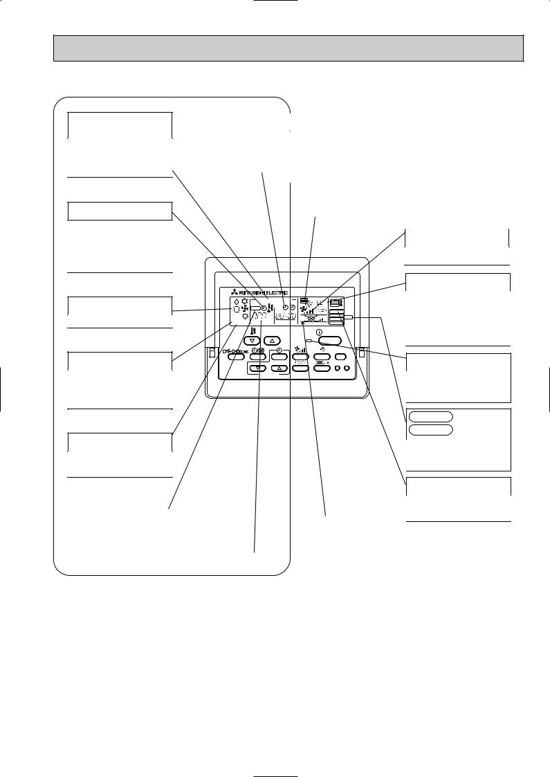
WIRED REMOTE CONTROLLER

1 
 PART NAMES AND FUNCTIONS
Indoor Unit
SEZ-A12AR.TH
SEZ-A18AR.TH
SEZ-A24AR.TH
Air outlet
Air outlet duct flange
inlet
(Selecting the either back side or bottom side)
Wired remote controller
On the controls are set, the same operation mode can be repeated by simply pressing the ON/OFF button.
● Operation buttons
|
|
TEMP. ADJUSTMENT button |
|
|
TIME SETTING button |
|
|
|
|
||||
|
|
|
|
|
|
|
|
This sets the room temperature. The |
|
|
This sets the current time, start time |
|
|
|
temperature setting can be performed |
|
|
and stop time. |
|
|
|
in 1: units |
|
|
|
|
|
|
|
|
|
|
||
|
|
Setting range |
|
|
|
|
|
|
Cooling 19: to 30: |
|
|
|
|
|
|
Heating 17: to 28: |
|
|
|
|
|
|
|
|
|
|
|
TIMER button
This switches between continuous operation and the timer operation.
OPERATION SWITCH button
Press this button to switch the cooling, electronic dry (dehumidify), automatic and heating modes.
|
CENTRALLY CONTROLLED |
1Hr. |
|
|
|
|
ON OFF |
|
˚C |
|
CHECK |
CLOCK |
|
|
|
|
|
|
|
|
|
|
|
FILTER |
|
˚C |
|
|
CHECK MODE |
STAND BY |
ERROR CODE |
|
TEST RUN |
|
|
NOT AVAILABLE |
FUNCTION |
||
DEFROST |
|
|||
|
|
|||
|
TEMP. |
|
|
ON/OFF |
FILTER
CHECK TEST
PAR-20MAA |
TIMER SET |
FAN SPEED button
This sets the ventilation fan speed.
ON/OFF button
This switches between the operation and stop modes each time it is pressed. The lamp on this button lights during operation.
AIR DIRECTION button
This adjusts the vertical angle of the ventilation.
(Not available for this model.)
FILTER button
This resets the filter service indication display
LOUVER button
This switch the horizontal fan motion ON and OFF.
(Not available for this model.)
VENTILATION button
This sets the ventilation fan speed.
(Not available for this model.)
CHECK-TEST RUN button
Only press this button to perform an inspection check or test operation. Do not use it for normal operation.
2
● Display
CENTRALLY CONTROLLED display
This indicates when the unit is controlled by optional features such as central control type remote controller.
TIMER display
This indicates when the continuous operation and time operation modes are set.
It also display the time for the timer operation at the same time as when it is set.
OPERATION MODE display
This indicates the operation mode.
STANDBY display
The [STANDBY] symbol is only displayed from the time the heating operation starts unit the heated air begins to blow.
DEFROST display
This indicates when the defrost operation is performed.
CLOCK display |
|
In this display example on the bot- |
||
|
tom left, a condition where all dis- |
|||
|
|
|||
The current time , start time and stop |
|
play lamps light is shown for expla- |
||
time can be displayed in ten second |
|
nation purposes although this differs |
||
intervals by pressing the time switch |
|
from actual operation. |
||
button. The start time or stop time is |
|
|||
|
|
|
|
|
always displayed during the timer |
|
|
|
|
operation. |
|
|
|
|
|
|
AIR DIRECTION display |
|
|
|
|
|
|
|
|
|
This displays the air direction. |
|
|
|
|
|
|
|
|
|
(Not available for this model.) |
||
|
|
|
|
|
|
|
|
AIR SPEED display |
|
|
|
|
|
|
|
CENTRALLY CONTROLLED |
1Hr. |
|
|
|
|
ON OFF |
|
˚C |
|
CHECK |
CLOCK |
|
|
|
|
|
|
|
|
|
|
|
FILTER |
|
˚C |
|
|
CHECK MODE |
STAND BY |
ERROR CODE |
|
TEST RUN |
|
|
NOT AVAILABLE |
FUNCTION |
||
DEFROST |
|
|||
|
|
|||
|
TEMP. |
|
|
ON/OFF |
FILTER
CHECK TEST
PAR-20MAA |
TIMER SET |
The selected fan speed is displayed.
ROOM TEMPERATURE display
The temperature of the suction air is displayed during operation. The display range is 8°C to 39°C. The display flashes 8°C when the actual temperature is less than 8°C and flashes 39°C when the actual temperature is greater than 39°C.
Operation lamp
This lamp lights during operation, goes off when the unit stops and flashes when a malfunction occurs.
CHECK MODE
display
TEST RUN
This display lights in the check mode or when a test operation is performed.
CHECK display |
|
|
|
|
|
|
|
SET TEMPERATURE display |
|
POWER display |
|
This indicates when a malfunction |
|||||
|
|
|
|
||
has occurred in the unit which should |
|
This displays the selected setting |
|
This lamp lights when electricity is |
|
be checked. |
|
|
|||
|
temperature. |
|
supplied to the unit. |
||
|
|
|
|||
|
|
|
|
|
Caution
FILTER display
This lamp lights when the filter need to be cleaned.
●Only the Power display lights when the unit is stopped and power supplied to the unit.
●When the central control remote control unit, which is sold separately, is used the ON-OFF button, operation switch button and  TEMP. adjustment button do not operate.
●“NOT AVAILABLE” is displayed when the Air speed button are pressed.This indicates that this room unit is not equipped with the fan direction adjustment function and the louver function.
●When power is turned ON for the first time, it is normal that “H0” is displayed on the room temperature indication (For max. 2minutes). Please wait until this “H0” indication disappear then start the operation.
3

2 
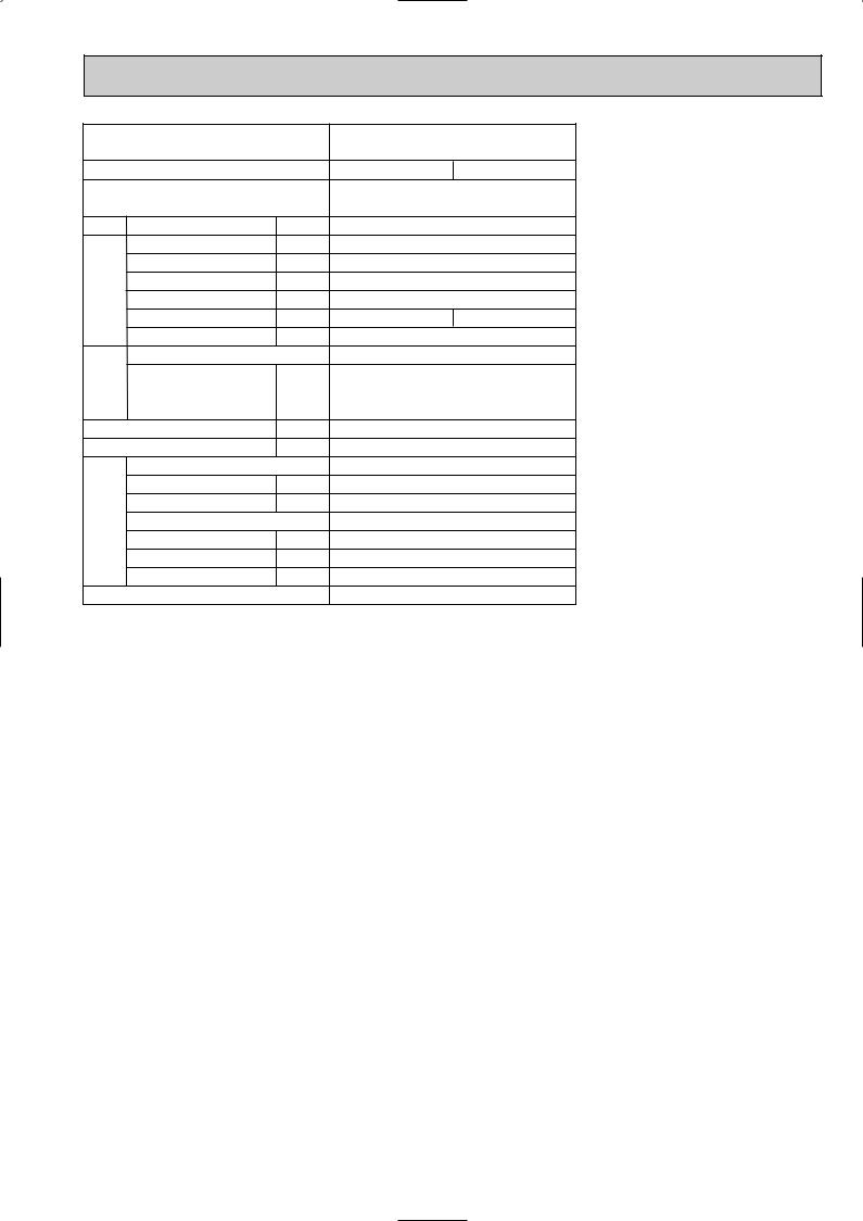
 SPECIFICATIONS
|
|
Indoor model |
|
SEZ-A12AR.TH |
|||
|
|
Function |
|
|
Cooling |
Heating |
|
|
|
Power supply |
|
Single phase |
|||
|
|
|
230V, 50Hz |
||||
|
|
|
|
|
|||
Capacity Air flow (High/Low) |
|
K /h |
780/600 |
||||
|
|
Power outlet |
|
A |
10 |
|
|
Electrical |
data |
Running current 1 |
A |
0.21 |
|
||
Power input Rated frequency |
W |
33 |
|
||||
|
|
|
|||||
|
|
Auxiliary heater |
|
A(kW) |
— |
|
|
|
|
Power factor 1 |
|
% |
94 |
95 |
|
|
|
Fan motor current |
1 |
A |
0.21 |
|
|
Fan |
motor |
Model |
|
" |
PK6V19-EF |
||
|
|
BLU-YLW : 26.5 |
YLW-BRN : 13.2 |
||||
|
|
Winding |
|
|
WHT-BLK : 251.4 |
BLK-BLU : 19.9 |
|
|
|
|
|
|
|
||
|
|
resistance (at20:) |
|
|
BRN-RED : 50.0 |
||
|
|
|
|
|
|||
|
|
Dimensions WoHoD |
mm |
1100o270o700 |
|||
|
|
Weight |
|
kg |
33.5 |
|
|
remarks |
Air direction |
|
|
1 |
|
||
Sound level (High/Low) |
dB(A) |
35/30 |
|||||
|
|
||||||
|
|
Fan speed (High/Low) |
rpm |
770/630 |
|||
Special |
Fan speed regulator |
|
3 |
|
|||
Thermistor RT11 (at 25:) |
k" |
10 |
|
||||
|
|
|
|||||
|
|
Thermistor RT12 (at 25:) |
k" |
10 |
|
||
|
|
Thermistor RT13 (at 25:) |
k" |
10 |
|
||
|
|
Remote controller model |
|
PAR-20MAA |
|||
NOTE : Test conditions are based on ISO 5151 |
|
||||||
|
|
Cooling : Indoor |
D.B. 27: W.B. 19: |
|
|||
|
|
Outdoor D.B. 35: W.B. 24: |
|
||||
|
|
Heating : Indoor |
D.B. 20: W.B. 5: |
|
|||
|
|
Outdoor D.B. 7: W.B. 6: |
|
||||
Refrigerant piping length (one way): 5m
1 Measured under rated operating frequency.
SEZ-A18AR.TH
Cooling |
Heating |
Single phase |
|
230V, 50Hz |
|
1020/720 |
|
20 |
|
0.27 |
|
49 |
|
— |
|
97 |
98 |
0.27 |
|
PK6V32-EF |
|
WHT-BLK : 161.9 |
BLK-BLU : 50.3 |
BLU-YLW : 18.7 YLW-BRN : 8.0
BRN-RED : 39.2
1100o270o700
33.5
1
39/31
840/640
3
10
10
10 PAR-20MAA
Specifications and rating conditions of main electric parts
INDOOR UNIT
Item |
Model |
SEZ-A12AR.TH SEZ-A18AR.TH SEZ-A24AR.TH |
|
||
|
|
|
Indoor fan capacitor |
(C1) |
SEZ-A12/18AR.TH : 2.5+ 440V SEZ-A24AR.TH : 3.0+ 440V |
Fuse |
(FUSE) |
250V 3.15A |
Varistor |
(ZNR1) |
ERZV10D471 |
Terminal block |
(TB) |
POWER SUPPLY : 3P TO OUTDOOR UNIT : 4P |
Contactor |
(52C) |
G4A-1A-E-PS 12V DC |
Indoor fan motor thermal fuse |
145:i2: |
|
4
|
|
Indoor model |
|
|
|
Function |
|
|
|
Power supply |
|
Capacity Air flow (High/Low) |
|||
|
|
Power outlet |
|
Electrical |
data |
Running current 1 |
|
Power input Rated frequency |
|||
|
|
||
|
|
Auxiliary heater |
|
|
|
Power factor 1 |
|
|
|
Fan motor current 1 |
|
Fan |
motor |
Model |
|
Winding |
|||
|
|
||
|
|
resistance (at20:) |
|
|
|
Dimensions WoHoD |
|
|
|
Weight |
|
remarks |
Air direction |
||
Sound level(High/Low) |
|||
|
|
||
|
|
Fan speed(High/Low) |
|
Special |
Fan speed regulator |
||
|
|||
Thermistor RT11 (at 25:)
Thermistor RT12 (at 25:)
Thermistor RT13 (at 25:) Remote controller model
|
SEZ-A24AR.TH |
|
|
Cooling |
Heating |
|
|
Single phase |
|
|
230V, 50Hz |
K /h |
|
1200/720 |
A |
|
20 |
A |
|
0.34 |
W |
|
64 |
A(kW) |
|
— |
% |
98 |
98 |
A |
|
0.34 |
|
|
PK6V50-EF |
|
WHT-BLK : 101.1 BLK-BLU : 56.1 |
|
"BLU-YLW : 14.7 YLW-BRN : 6.7
|
BRN-RED : 28.2 |
mm |
1100o270o700 |
kg |
33.5 |
|
1 |
dB(A) |
43/32 |
rpm |
890/660 |
|
3 |
k" |
10 |
k" |
10 |
k" |
10 |
|
PAR-20MAA |
NOTE : Test conditions are based on ISO 5151
Cooling : Indoor |
D.B. 27: W.B. 19: |
Outdoor D.B. 35: W.B. 24: |
|
Heating : Indoor |
D.B. 20: W.B. 15: |
Outdoor D.B. 7: W.B. 6: Refrigerant piping length (one way): 5m
1 Measured under rated operating frequency.
5

NOISE CRITERION CURVES
<50Hz>
SEZ-A12AR.TH |
NOTCH SPL(dB) LINE |
|
|
|
|
|
|
|
Hi |
35 |
|
|
|
|
|
|
|
|
Lo |
30 |
|
|
90 |
|
|
|
|
|
|
|
|
bar) |
80 |
|
|
|
|
|
|
|
|
= 0.0002 |
70 |
|
|
|
|
|
|
|
|
dB (0 dB |
|
|
|
|
|
|
|
NC-70 |
|
|
|
|
|
|
|
|
|
||
60 |
|
|
|
|
|
|
|
|
|
LEVEL, |
|
|
|
|
|
|
|
|
|
|
|
|
|
|
|
|
|
NC-60 |
|
|
|
|
|
|
|
|
|
|
|
PRESSURE |
50 |
|
|
|
|
|
|
|
|
|
|
|
|
|
|
|
|
NC-50 |
|
40 |
|
|
|
|
|
|
|
|
|
SOUND |
|
|
|
|
|
|
|
|
|
|
|
|
|
|
|
|
|
NC-40 |
|
|
|
|
|
|
|
|
|
|
|
BAND |
30 |
|
|
|
|
|
|
|
|
|
|
|
|
|
|
|
|
NC-30 |
|
|
|
|
|
|
|
|
|
|
|
OCTAVE |
20 |
APPROXIMATE |
|
|
|
|
|
|
|
|
TERESHOLD OF |
|
|
|
|
|
|
||
|
HEARING FOR |
|
|
|
|
|
NC-20 |
||
|
|
CONTINUOUS |
|
|
|
|
|
||
|
|
|
|
|
|
|
|
||
|
|
NOISE |
|
|
|
|
|
|
|
|
10 |
63 |
125 |
250 |
500 |
1000 |
2000 |
4000 |
8000 |
|
|
||||||||
BAND CENTER FREQUENCIES, Hz
<50Hz>
SEZ-A18AR.TH |
NOTCH SPL(dB) LINE |
|
|
|
|
|
|
|
Hi |
39 |
|
|
|
|
|
|
|
|
Lo |
31 |
|
|
90 |
|
|
|
|
|
|
|
|
bar) |
80 |
|
|
|
|
|
|
|
|
= 0.0002 |
70 |
|
|
|
|
|
|
|
|
dB (0 dB |
|
|
|
|
|
|
|
NC-70 |
|
|
|
|
|
|
|
|
|
||
60 |
|
|
|
|
|
|
|
|
|
LEVEL, |
|
|
|
|
|
|
|
|
|
|
|
|
|
|
|
|
|
NC-60 |
|
|
|
|
|
|
|
|
|
|
|
PRESSURE |
50 |
|
|
|
|
|
|
|
|
|
|
|
|
|
|
|
|
NC-50 |
|
40 |
|
|
|
|
|
|
|
|
|
SOUND |
|
|
|
|
|
|
|
|
|
|
|
|
|
|
|
|
|
NC-40 |
|
|
|
|
|
|
|
|
|
|
|
BAND |
30 |
|
|
|
|
|
|
|
|
|
|
|
|
|
|
|
|
NC-30 |
|
|
|
|
|
|
|
|
|
|
|
OCTAVE |
20 |
APPROXIMATE |
|
|
|
|
|
|
|
|
TERESHOLD OF |
|
|
|
|
|
|
||
|
HEARING FOR |
|
|
|
|
|
NC-20 |
||
|
|
CONTINUOUS |
|
|
|
|
|
||
|
|
|
|
|
|
|
|
||
|
|
NOISE |
|
|
|
|
|
|
|
|
10 |
63 |
125 |
250 |
500 |
1000 |
2000 |
4000 |
8000 |
|
|
||||||||
BAND CENTER FREQUENCIES, Hz
<50Hz>
SEZ-A24AR.TH |
NOTCH SPL(dB) LINE |
|
|
|
|
|
|
|
Hi |
43 |
|
|
|
|
|
|
|
|
|
|
Lo |
32 |
|
|
|
|
90 |
|
|
|
|
|
|
|
|
|
|
bar) |
80 |
|
|
|
|
|
|
|
|
|
UNIT |
= 0.0002 |
70 |
|
|
|
|
|
|
|
|
|
|
dB(0dB |
|
|
|
|
|
|
|
NC-70 |
|
|
|
|
|
|
|
|
|
|
|
|
|
||
|
|
|
|
|
|
|
|
|
|
|
|
LEVEL, |
60 |
|
|
|
|
|
|
|
NC-60 |
External static |
1.5m |
|
|
|
|
|
|
|
|
pressure 30Pa |
|||
|
|
|
|
|
|
|
|
|
|
||
PRESSURE |
|
|
|
|
|
|
|
|
|
|
|
50 |
|
|
|
|
|
|
|
|
|
|
|
|
|
|
|
|
|
|
|
|
|
|
|
|
|
|
|
|
|
|
|
|
NC-50 |
|
|
SOUND |
40 |
|
|
|
|
|
|
|
|
|
MICROPHONE |
|
|
|
|
|
|
|
|
NC-40 |
|
|
|
BAND |
|
|
|
|
|
|
|
|
|
|
|
30 |
|
|
|
|
|
|
|
|
|
|
|
|
|
|
|
|
|
|
|
|
|
|
|
OCTAVE |
|
|
|
|
|
|
|
|
NC-30 |
|
|
20 |
HEARING FOR |
|
|
|
|
|
|
|
|
||
|
APPROXIMATE |
|
|
|
|
|
|
|
|
||
|
|
TERESHOLD OF |
|
|
|
|
|
|
|
|
|
|
|
CONTINUOUS |
|
|
|
|
|
NC-20 |
|
|
|
|
|
|
|
|
|
|
|
|
|
||
|
|
NOISE |
|
|
|
|
|
|
|
|
|
|
10 |
63 |
125 |
250 |
500 |
1000 |
2000 |
4000 |
8000 |
|
|
|
|
|
|
||||||||
BAND CENTER FREQUENCIES, Hz
NOTE: The sound level is measured in an anechoic room where echoes are few, when compressor stops. The sound may be bigger than displayed level under actual installation condition by surrounding echoes. The sound level can be higher by about 2 dB than the displayed level during cooling and heating operation.
6
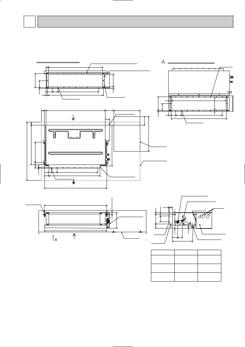
3 OUTLINES AND DIMENSIONS
SEZ-A12AR.TH SEZ-A18AR.TH SEZ-A24AR.TH
Unit : mm
Air inlet (rear side) dimensions |
In case of bottom side suction, |
|
mount the PLATE (A) on the rear side. |
|
|
42 |
930 |
|
|
|
(Inlet size) |
240 |
120 |
|
|
|
12.5 |
77.5 100 |
7o100=700 |
|
29 |
955 |
|
|
|
||
|
|
|
24-[2.9 holes |
|
|
5027 |
1016 |
50
1000 |
680 38 |
pitch |
Suspensionbolt |
||
|
350 |
|
|
60 |
50 |
|
|
(10) |
40 |
100 |
50 |
|
Air inlet (rear side)
wSelect the either
back side or bottom side.
7o100=700
880
9o2-[2.9 holes
Air outlet
After installation, remove the
transportation support PLATE (B). |
|
||
215 |
(Inlet size) |
|
|
25 |
|
|
|
PLATE (B) o2 |
|
|
|
|
|
|
51 |
150 |
450 |
240 |
120 |
|
|
||
|
Electrical parts box |
12.5 |
|
77 |
|
|
|
|
150 |
|
|
|
|
|
|
|
|
600 |
|
700 |
|
Access door |
|
|
|
||
|
|
Service space |
|
|
|
(It is necessary to |
|
|
|
maintain a working |
|
|
|
service area from |
|
|
|
the ceiling.) |
|
Air outlet duct flange |
|
|
|
Air inlet (bottom side) dimensions
PLATE (A)
|
930 |
215 |
size)(Inlet |
|
(Inlet size) |
|
|
3977.5 100 |
7o100=700 |
25 |
|
|
|
||
|
955 |
|
|
24-[2.9 holes
1070
Suspension bolt pitch
Refrigerent pipe (gas)
Suspension bolt |
|
more |
M10 or 3/8 |
(1070) |
|
(procure locally) |
or |
|
|
(Suspension bolt pitch) |
|
|
20 |
|
|
|
30 |
Electrical parts box |
|
270 |
1100 |
|
Air inlet |
Access door |
(bottom side) |
w Select the either back side or bottom side.
|
(10) |
50 |
25 |
32.5 |
20 |
170 |
100 |
|
75 |
|
108 |
|
|
2o2-[2.9 holes
94
Air outlet duct flange
25
80
350
Refrigerent pipe (liquid)
Terminal
block
Wiring entry
Electrical parts box
Drain plug R1 male
Models
SEZ-A12AR
SEZ-A18AR
SEZ-A24AR
Refrigerent pipe |
Refrigerent pipe |
(liquid) |
(gas) |
[6.35mm |
[9.52mm |
flared connection |
flared connection |
1/4F |
3/8F |
[6.35mm |
[12.7mm |
flared connection |
flared connection |
1/4F |
1/2F |
[6.35mm |
[15.88mm |
flared connection |
flared connection |
1/4F |
5/8F |
7
4 
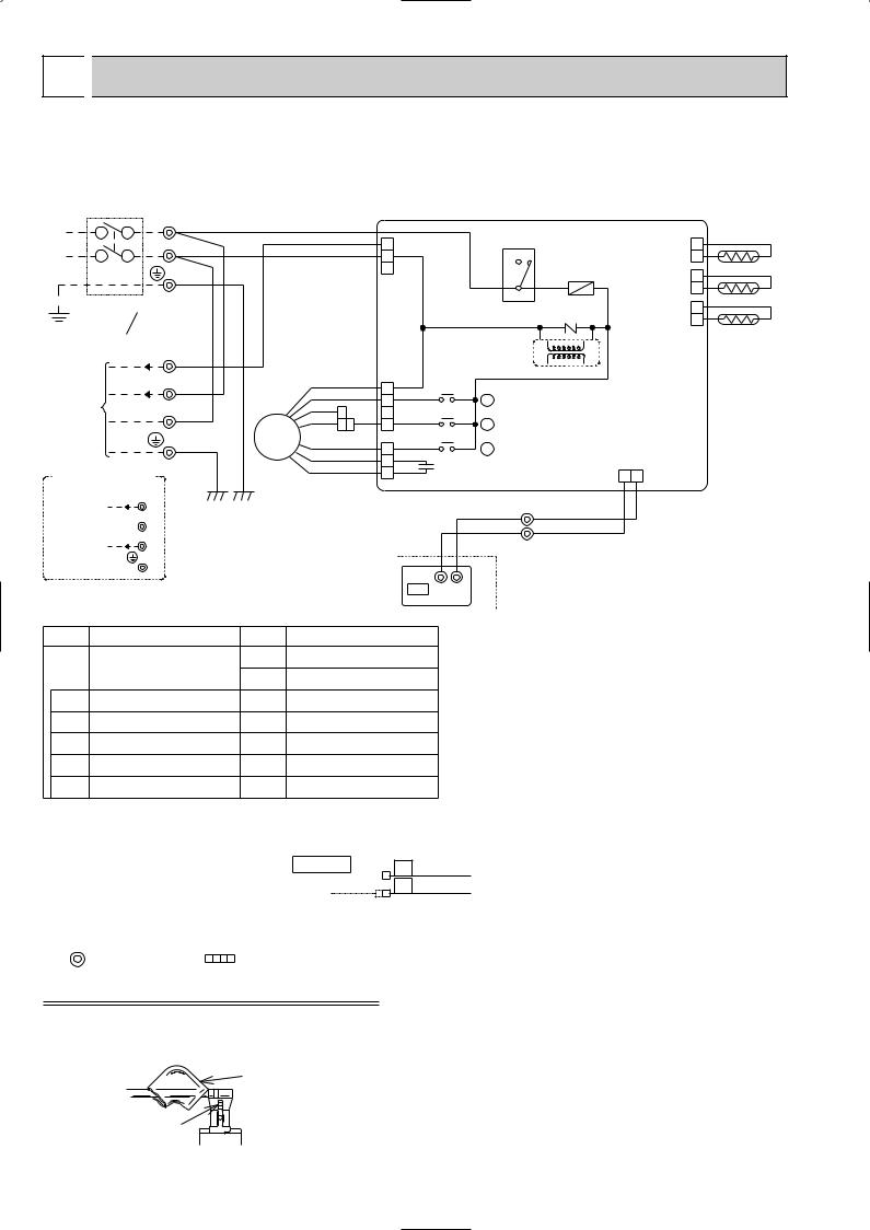
 WIRING DIAGRAM
SEZ-A12AR.TH
SEZ-A18AR.TH
SEZ-A24AR.TH
CIRCUIT BREAKER |
TB |
||
|
|
L |
w WHT |
|
|
N |
w BLU |
|
|
|
GRN/YLW |
POWER SUPPLY |
|
||
~/N |
|
|
|
220-240V 220V |
|
||
50Hz |
60Hz |
|
|
|
|
TB |
|
12VDC |
3 |
w RED |
|
FOR A12 |
|
|
|
(1:1 SYSTEM) 220-240V~ |
2 |
w WHT |
|
TO OUTDOOR |
|
N |
w BLU |
|
|
|
|
UNIT |
|
|
|
CONNECTING |
|
|
GRN/YLW |
|
|
|
|
FOR A18/24 (1:1 SYSTEM) |
|
|
|
OR MULTI SYSTEM |
|
|
|
12V DC 3 |
|
|
|
TO OUTDOOR |
2 |
|
|
UNIT |
|
|
|
CONNECTING |
N |
|
|
[LEGEND] |
|
SYMBOL |
NAME |
I.B |
INDOOR CONTROLLER |
|
BOARD |
C1 |
FAN MOTOR CAPACITOR |
FUSE |
FUSE(3.15A) |
X2,X4,X5 RELAY(FAN MOTOR) |
|
ZNR1 |
VARISTOR |
52C |
COMPRESSOR CONTACTOR |
I.B
|
|
5 |
CND(POWER) |
52C |
|
CN29 |
2 |
||
|
|
3 |
RED |
|
4 |
|
(2 PHASE) |
1 |
|
|
|
1 |
|
|
|
|
BLK |
RT13 |
|
|
|
|
|
|
FUSE |
CN21 |
|||
|
|
|
|
|
w |
2 |
|||
|
|
|
|
|
(LIQUID) |
||||
|
|
|
|
|
|
|
1 |
||
|
|
|
|
|
3 |
|
WHT |
||
|
|
|
|
|
|
|
CN20 |
RT12 |
|
|
|
|
|
|
|
ZNR1 |
2 |
||
|
|
|
|
|
|
(INTAKE) |
1 |
||
|
|
|
|
|
|
|
RED |
RT11 |
|
|
|
|
|
|
|
|
|
||
|
|
|
|
TRANS |
|
|
|
||
|
|
|
FAN1 |
DC13.1V |
|
|
|
||
|
|
|
(FAN) |
|
|
|
|
|
|
|
WHT |
7 |
WHT |
X2 |
|
|
|
|
|
|
BLK |
|
|
|
|
|
|||
|
5 |
|
|
|
|
|
|||
|
BLU |
|
X2 |
|
|
|
|
||
|
3 |
|
X4 |
|
|
|
|
||
|
|
|
|
|
|
|
|||
|
YLW |
BLU 1 |
|
|
|
|
|
||
MF |
FAN2(FAN) |
X4 |
|
|
|
|
|||
BRN |
|
X5 |
|
CN22 |
|
||||
|
5 WHT |
X5 |
|
|
|||||
|
RED |
3 |
|
|
|
(REMOCON) |
|
||
|
ORN |
C1 |
|
|
BLU |
|
|||
|
1 |
|
|
|
|||||
|
|
|
|
|
1 |
2 |
|
||
|
|
|
|
|
|
|
|||
|
|
|
TRANSMISSION WIRE |
TB 2 |
BLU |
|
|
||
|
|
|
|
DC12V |
|
|
|
||
|
|
|
|
|
1 |
BLU |
|
|
|
|
|
|
|
R.B |
|
|
|
|
|
|
|
|
CN2 |
2 |
|
|
|
|
|
|
|
|
1 |
|
|
|
|
||
|
|
|
TB |
|
|
|
|
||
SYMBOL |
|
NAME |
|
The 12V DC is NOT always against the ground. |
|||||
MF |
FAN MOTOR |
|
|||||||
|
Terminal 3 has 12V DC against terminal N. |
||||||||
|
ROOM TEMPERATURE |
||||||||
RT11 |
However, between 3 and 2, these terminals are |
||||||||
THERMISTOR |
|
||||||||
|
|
NOT electrically insulated by the transformer or |
|||||||
RT12 |
PIPE TEMPERATURE |
|
|||||||
THERMISTOR / LIQUID |
other device. |
|
|
||||||
|
|
|
|||||||
RT13 |
CONDENSER / EVAPORATOR |
|
|
|
|
|
|||
TEMPERATURE THERMISTOR |
|
|
|
|
|
||||
|
|
|
|
|
|
||||
TB |
TERMINAL BLOCK |
|
|
|
|
|
|
||
R.B |
REMOTE CONTROLLER |
|
|
|
|
|
|||
BOARD |
|
|
|
|
|
|
|
||
|
|
|
|
|
|
|
|
||
NOTES:
1.Since the indoor fan motor(MF) is connected with 50Hz power,if 60Hz power is used, change the wiring connection showing fig: *1
Indoor Fan Motor(MF) for 60Hz
BLUE
2.About the outdoor side electric wiring refer to the outdoor unit electlic wiring diagram for servicing. 3.Use copper conductors only. (For field wiring)
4.Symbols below indicate.
: Terminal block : Connector
How to remove the terminals shown at " w " mark.
" w " shows the terminals with a lock mechanism, so they cannot be removed when you pull the lead wire. Be sure to pull the wire by pushing the locking lever (projected part) of the terminal with a finger.
sleeve 1Slide the sleeve.
2Pull the wire while pushing the locking lever.
locking lever
8
 Loading...