


SEZ-KD35VAQ
Air-Conditioners
SEZ-KD25,KD35,KD50,KD60,KD71VA
OPERATION MANUAL
For safe and correct use, please read this operation manual thoroughly before operating the air-conditioner unit.
BEDIENUNGSHANDBUCH
Zum sicheren und einwandfreien Gebrauch der Klimaanlage dieses Bedienungshandbuch vor Inbetriebnahme
gründlich durchlesen.
MANUEL D’UTILISATION
Pour une utilisation correcte sans risques, veuillez lire le manuel d’utilisation en entier avant de vous servir du
climatiseur.
MANUAL DE INSTRUCCIONES
Lea este manual de instrucciones hasta el final antes de poner en marcha la unidad de aire acondicionado
para garantizar un uso seguro y correcto.
ISTRUZIONI DI FUNZIONAMENTO
Leggere attentamente questi istruzioni di funzionamento prima di avviare l’unità, per un uso corretto e sicuro
della stessa.
BEDIENINGSHANDLEIDING
Voor een veilig en juist gebruik moet u deze bedieningshandleiding grondig doorlezen voordat u de
airconditioner gebruikt.
DRIFTSMANUAL
Läs denna driftsmanual noga för säkert och korrekt bruk innan luftkonditioneringen används.
DRIFTSMANUAL
Læs venligst denne driftsmanual grundigt før airconditionanlægget betjenes af hensyn til sikker og korrekt brug.
FOR USER
FÜR BENUTZER
POUR L’UTILISATEUR
PARA EL USUARIO
PER L’UTENTE
VOOR DE GEBRUIKER
FÖR ANVÄNDAREN
TIL BRUGER
English
Deutsch
Français
Español
Italiano
Nederlands
Svenska
Dansk
MANUAL DE OPERAÇÃO
Para segurança e utilização correctas, leia atentamente o manual de operação antes de pôr a funcionar a
unidade de ar condicionado.
E°XEIPI¢IO O¢H°IøN XPH™Eø™
°И· ·ЫК¿ПВИ· О·И ЫˆЫЩ‹ ¯Ъ‹ЫЛ, ·Ъ·О·ПВ›ЫЩВ ‰И·‚¿ЫВЩВ ЪФЫВ¯ЩИО¿ ·˘Щfi ЩФ ВБ¯ВИЪ›‰ИФ ¯Ъ‹ЫВˆ˜ ЪИУ ı¤ЫВЩВ ЫВ
ПВИЩФ˘ЪБ›· ЩЛ МФУ¿‰· ОПИМ·ЩИЫМФ‡.
РУКОВОДСТВО ПО ЭКСПЛУАТАЦИИ
Для обеспечения правильного и безопасного использования следует ознакомиться с инструкциями, указанными в
данном руководстве по эксплуатации, тщательным образом до того, как приступать к использованию кондиционера.
‹fiLETME ELK‹TABI
Emniyetli ve do¤ru biçimde nas›l kullan›laca¤›n› ö¤renmek için lütfen klima cihaz›n› iflletmeden önce bu
elkitab›n› dikkatle okuyunuz.
PARA O UTILIZADOR
Português
°π∞ ∆√¡ Ã∏™∆∏
∂ППЛУИО¿
ДЛЯ ПОЛЬЗОВАТЕЛЯ
Русский
KULLANICI ‹Ç‹N
Türkçe
Contents
1. Safety Precautions ................................................................ 2
2. Parts Names .......................................................................... 2
3. Screen Configuration............................................................. 4
4. Setting the Day of the Week and Time .................................. 4
5. Operation............................................................................... 5
6. Timer ..................................................................................... 6
Note (Marking
for WEEE)
This symbol mark is for EU countries only.
This symbol mark is according to the directive 2002/96/EC Article 10 Information for users and Annex IV.
Your MITSUBISHI ELECTRIC product is designed and manufactured with high quality materials and components which can be
recycled and reused.
This symbol means that electrical and electronic equipment, at their end-of-life, should be disposed of separately from your household waste.
Please, dispose of this equipment at your local community waste collection/recycling centre.
In the European Union there are separate collection systems for used electrical and electronic product.
Please, help us to conserve the environment we live in!
1. Safety Precautions
s Before installing the unit, make sure you read all the “Safety
Precautions”.
s The “Safety Precautions” provide very important points regard-
ing safety. Make sure you follow them.
s Please report to or take consent by the supply authority be-
fore connection to the system.
7. Other Functions ..................................................................... 9
8. Function Selection ............................................................... 10
9. Care and Cleaning .............................................................. 14
10. Trouble Shooting ................................................................ 15
11. Installation, relocation and inspection ............................... 16
12. Specifications .................................................................... 17
Symbols used in the text
Warning:
Describes precautions that should be observed to prevent danger of
injury or death to the user.
Caution:
Describes precautions that should be observed to prevent damage
to the unit.
Symbols used in the illustrations
: Indicates a part which must be grounded.
Warning:
• The unit must not be installed by the user. Ask the dealer or an
authorized company to install the unit. If the unit is installed improperly, water leakage, electric shock or fire may result.
• Do not stand on, or place any items on the unit.
• Do not splash water over the unit and do not touch the unit with
wet hands. An electric shock may result.
• Do not spray combustible gas close to the unit. Fire may result.
• Do not place a gas heater or any other open-flame appliance where
it will be exposed to the air discharged from the unit. Incomplete
combustion may result.
• Do not remove the front panel or the fan guard from the outdoor
unit when it is running.
Caution:
• Do not use any sharp object to push the buttons, as this may damage the remote controller.
• Never block or cover the indoor or outdoor unit’s intakes or outlets.
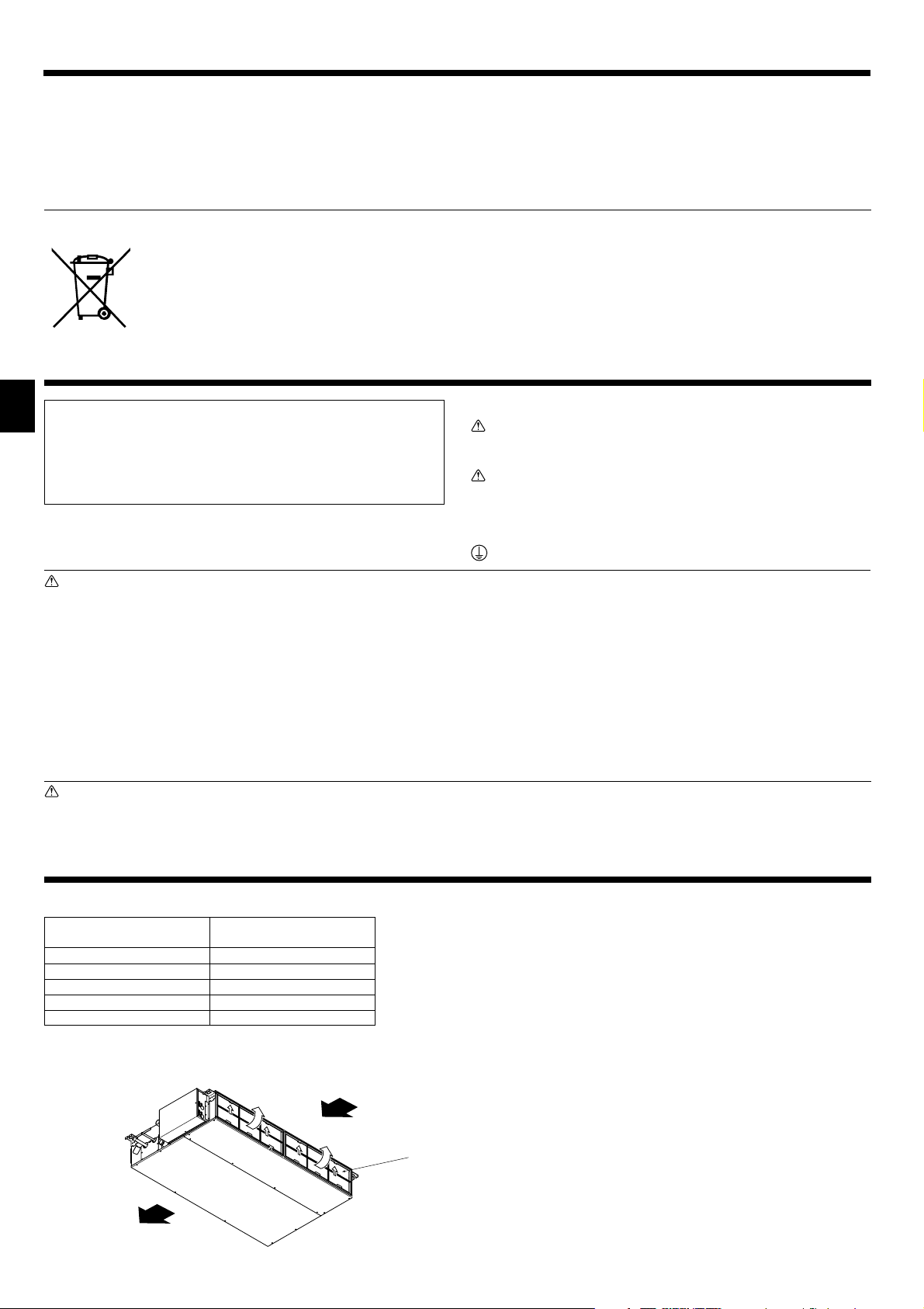
2. Parts Names
■ Indoor Unit
SEZ-KD·VA
Fan steps 3 steps
Vane –
Louver –
Filter Normal
Filter cleaning indication –
• When you notice exceptionally abnormal noise or vibration, stop
operation, turn off the power switch, and contact your dealer.
• Never insert fingers, sticks etc. into the intakes or outlets.
• If you detect odd smells, stop using the unit, turn off the power
switch and consult your dealer. Otherwise, a breakdown, electric
shock or fire may result.
• This air conditioner is NOT intended for use by children or infirm
persons without supervision.
• Young children must be supervised to ensure that they do not play
with the air conditioner.
•
If the refrigeration gas blows out or leaks, stop the operation of the
air conditioner, thoroughly ventilate the room, and contact your dealer.
Disposing of the unit
When you need to dispose of the unit, consult your dealer.
■ SEZ-KD·VA
Ceiling Concealed
Air outlet
2
Air intake
Filter
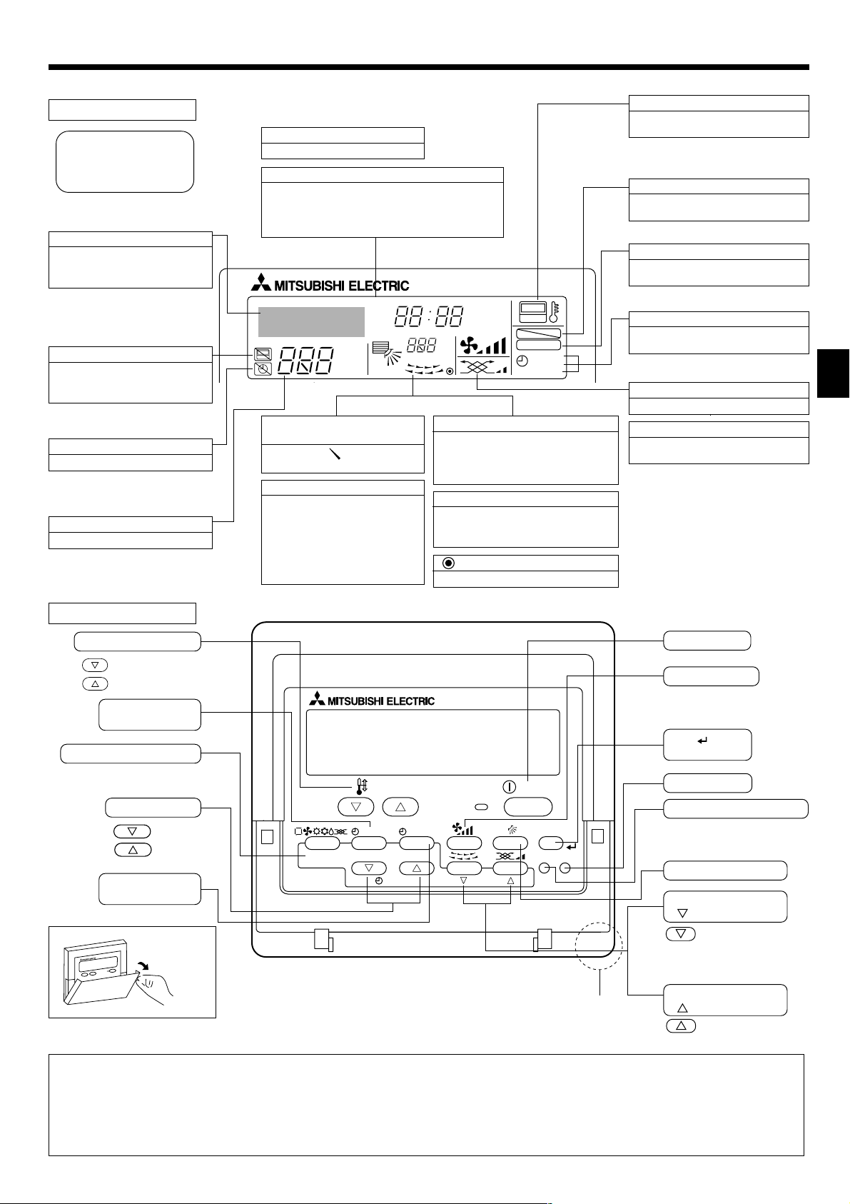
2. Parts Names
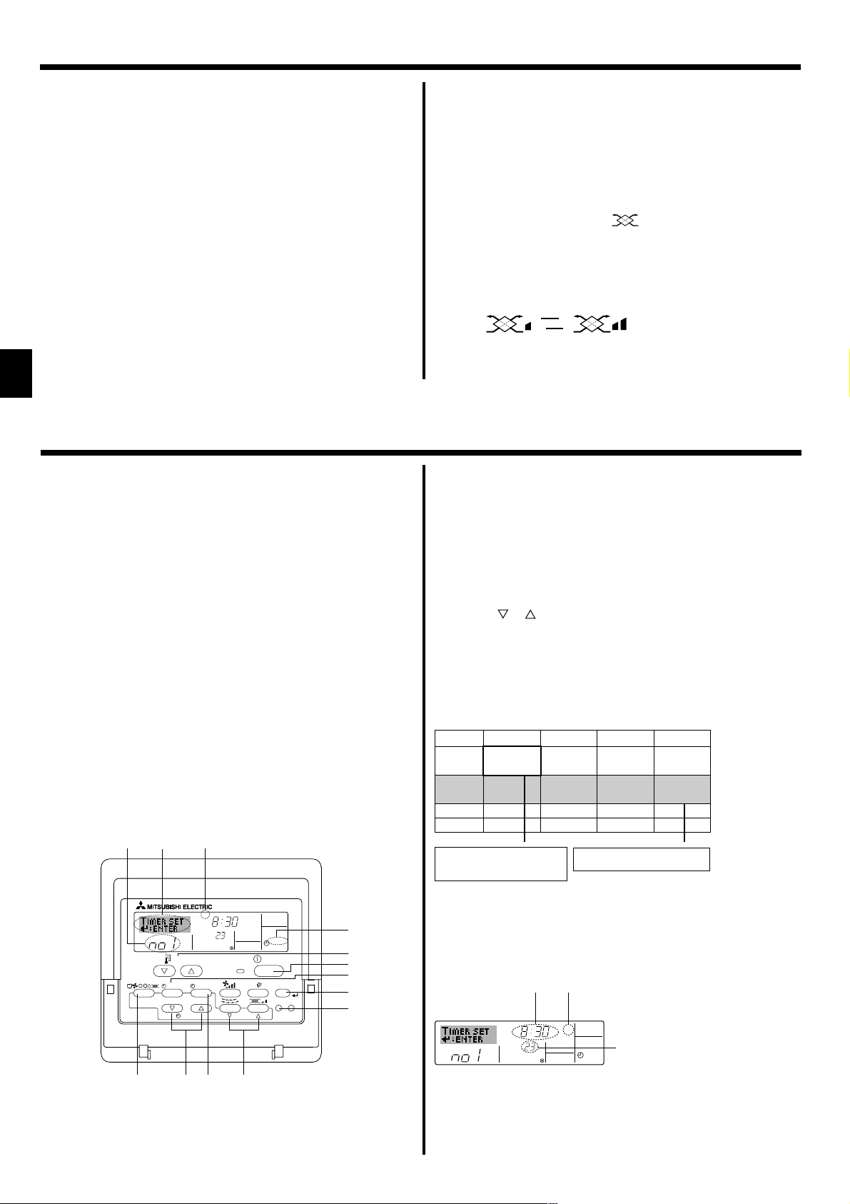
■ Wired Remote-Controller
Display Section
For purposes of this explanation,
all parts of the display are shown
as lit. During actual operation, only
the relevant items will be lit.
Identifies the current operation
Shows the operating mode, etc.
* Multilanguage display is sup-
ported.
“Centrally Controlled” indicator
Indicates that operation of the remote controller has been prohibited by a master controller.
“Timer is Off” indicator
Indicates that the timer is off.
Temperature Setting
Shows the target temperature.
Day-of-Week
Shows the current day of the week.
Time/Timer Display
Shows the current time, unless the simple or Auto Off
timer is set.
If the simple or Auto Off timer is set, shows the time
remaining.
TIME SUN MON TUE WED THU FRI SAT
TIMER
AFTER
ERROR CODE
˚F˚C
Hr
AFTER
˚F˚C
ONLY1Hr.
Up/Down Air Direction indicator
The indicator shows the direction of the outcoming airflow.
“One Hour Only” indicator
Displayed if the airflow is set to
weak and downward during COOL
or DRY mode. (Operation varies
according to model.)
The indicator goes off after one
hour, at which time the airflow direction also changes.
Room Temperature display
Shows the room temperature. The room
temperature display range is 8–39°C.
The display flashes if the temperature
is less than 8 °C or 39 °C or more.
Louver display
Indicates the action of the swing louver.
Does not appear if the louver is stationary.
(Power On indicator)
Indicates that the power is on.
ON
OFF
FUNCTION
FILTER
WEEKLY
SIMPLE
AUTO OFF
“Sensor” indication
Displayed when the remote controller
sensor is used.
“Locked” indicator
Indicates that remote controller buttons have been locked.
“Clean The Filter” indicator
Comes on when it is time to clean the
filter.
Timer indicators
The indicator comes on if the corresponding timer is set.
Fan Speed indicator
Shows the selected fan speed.
Ventilation indicator
Appears when the unit is running in
Ventilation mode.
Operation Section
Set Temperature buttons
Down
Up
Timer Menu button
(Monitor/Set button)
Mode button (Return button)
Set Time buttons
Back
Ahead
Timer On/Off button
(Set Day button)
Opening the
door.
TEMP.
MENU
MONITOR/SET
BACK DAY
PAR-21MAA
CLOCK
ON/OFF
ON/OFF
FILTER
CHECK
OPERATION
Built-in temperature sensor
CLEAR
TEST
ON/OFF button
Fan Speed button
Filter button
(<Enter> button)
Test Run button
Check button (Clear button)
Airflow Up/Down button
Louver button
(
Operation button)
To preceding operation
number.
Ventilation button
Operation button)
(
To next operation
number.
Note:
● “PLEASE WAIT” message
This message is displayed for approximately 3 minutes when power is supplied to the indoor unit or when the unit is recovering from a power failure.
● “NOT AVAILABLE” message
This message is displayed if a button is pressed to operate a function that the indoor unit does not have.
If a single remote controller is used to simultaneously operate multiple indoor units that are different models, this message will not be displayed if
any of the indoor units is equipped with the function.
3
2. Parts Names
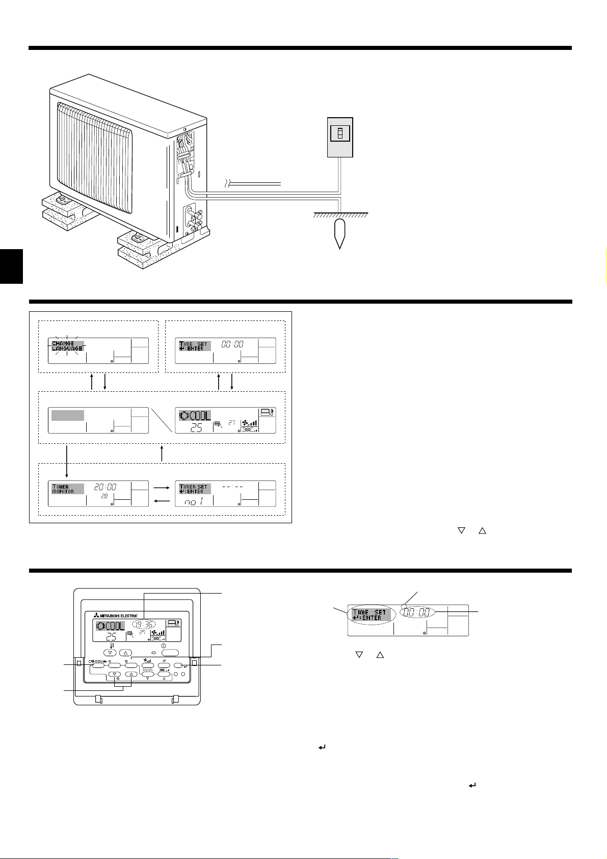
■ Outdoor unit
3. Screen Configuration
Function Selection of remote controller
ADC
Standard Control Screens
OFF ON
BC
Timer Monitor Timer Setup
MON
TIMER
OFF
˚F˚C
WEEKLY
Power
Ref. Pipes
Indoor-Outdoor
Connection wire
Earth
<Screen Types>
Set Day/Time
TIME SUN
For details on setting the language for the remote controller display, refer
to section 8. Function Selection.
The initial language setting is English.
● Function Selection of remote controller:
Set the functions and ranges available to the remote controller (timer functions, operating restrictions, etc.)
● Set Day/Time: Set the current day of the week or time.
● Standard Control Screens:
˚F˚C
˚C
View and set the air conditioning system’s operating status
● Timer Monitor: View the currently set timer (weekly timer, sim-
ple timer, or Auto Off timer)
● Timer Setup: Set the operation of any of the timers (weekly
timer, simple timer, or Auto Off timer).
SUN MON TUE WED THU FRI SAT
B
WEEKLY
<How to change the screen>
A :Hold down both the Mode button and the Timer On/Off button for 2
seconds.
B :Press the Timer Menu button.
C :Press the Mode (Return) button.
D :Press either of the Set Time buttons ( or ).
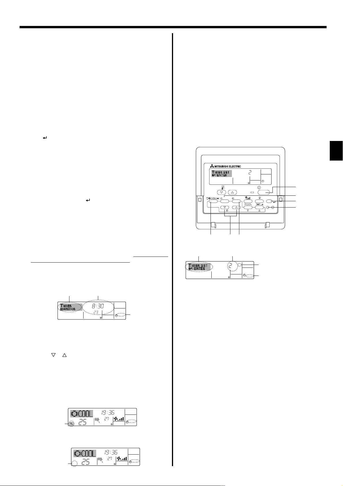
4. Setting the Day of the Week and Time
1
Day of the Week &
Time display
9
4
2
TEMP.
MENU
BACK DAY
MONITOR/SET
PAR-21MAA
˚C
CLOCK
TIME SUN
ON/OFF
˚C
OPERATION
ON/OFF
FILTER
CHECK
CLEAR
TEST
A
Note:
● The day and time will not appear if clock use has been disabled at Function
Selection of remote controller.
● After the power supply returns, the indoor unit does not operate for three
minutes. Above operation is normal.
4
Day of the Week Setting
3
2
TIME SUN
4
Time Setting
1. Press the or Set Time button A to show display 2.
2. Press the Timer On/Off (Set Day) button 9 to set the day.
* Each press advances the day shown at 3 : Sun → Mon → ... → Fri →
Sat.
3. Press the appropriate Set Time button A as necessary to set the time.
* As you hold the button down, the time (at 4) will increment first in
minute intervals, then in ten-minute intervals, and then in one-hour intervals.
4. After making the appropriate settings at Steps 2 and 3, press the Filter
button 4 to lock in the values.
Note:
● Your new entries at Steps 2 and 3 will be cancelled if you press the Mode
(Return) button
22
2 before pressing the Filter
22
button
44
4.
44
5. Press the Mode (Return) button 2 to complete the setting procedure.
This will return the display to the standard control screen, where 1 will
now show the newly set day and time.

5. Operation
5.1. Description of “AUTO RESTART FUNCTION”
• This unit is equipped with the auto restart function. When the main power is
turned on, the air conditioner will start operation automatically in the same
mode as set with the remote controller before the shutoff of main power.
• If the unit was set to off with the remote controller before the shutoff of
main power, it will remain stopped even after the main power is turned on.
• If the unit was in the TEST RUN before the shutoff of main power, it will
start operation, at main power on, in the same mode as set with the
remote controller before the TEST RUN.
6
2
4
5
3
3
2
TEMP.
MENU
BACK DAY
MONITOR/SET
PAR-21MAA
˚C
CLOCK
ON/OFF
˚C
OPERATION
ON/OFF
FILTER
CHECK
CLEAR
TEST
8
7
1
1
5
8
7
6
5.2. Turning ON/OFF
<To Start Operation>
■ Press the ON/OFF button 1.
• The ON lamp 1 and the display area come on.
Note:
● When the unit is restarted, initial settings are as follows.
Remote Controller settings
Mode
Temperature setting
Fan speed
Airflow up/down
Last operation mode
Last set temperature
Last set fan speed
COOL or DRY
Mode HEAT
FAN
Horiz. outlet
Last setting
Horiz. outlet
<To Stop Operation>
■ Press the ON/OFF button 1 again.
• The ON lamp 1 and the display area go dark.
Note:
Even if you press the ON/OFF button immediately after shutting down the operation is progress, the air conditioner will not start for about three minutes.
This is to prevent the internal components from being damaged.
5.3. Mode select
■ If the unit is off, press the ON/OFF button to turn it on.
• 1 The ON indicator should light up.
■ Press the operation mode ( ) button 2 and select the opera-
tion mode 2.
s
Cooling mode
Drying mode
Fan mode
Heating mode
Automatic (cooling/heating) mode
Ventillation mode
Only indicated on the following condition
Wired remote controller used
LOSSNAY connected
Information for multi system air conditioner (Outdoor
unit: MXZ series)
ss
sMulti system air conditioner (Outdoor unit: MXZ series) can con-
ss
nect two or more indoor units with one outdoor unit. According to
the capacity, two or more units can operate simultaneously.
• When you try to operate two or more indoor units with one outdoor unit
simultaneously, one for the cooling and the other for heating, the operation mode of the indoor unit that operates earlier is selected. The other
indoor units that will start the operation later cannot operate, indicating
an operation state in flashing.
In this case, please set all the indoor units to the same operation mode.
• There might be a case that the indoor unit, which is operating in
(AUTO) mode. Cannot change over to the operating mode (COOL ↔
HEAT) and becomes a state of standby.
• When indoor unit starts the operation while the defrosting of outdoor
unit is being done, it takes a few minutes (max. about 15 minutes) to
blow out the warm air.
• In the heating operation, though indoor unit that does not operate may
get warm or the sound of refrigerant flowing may be heard, they are not
malfunction. The reason is that the refrigerant continuously flows into it.
Automatic operation
■ According to a set temperature, cooling operation starts if the room tem-
perature is too hot and heating operation starts if the room temperature
is too cold.
■ During automatic operation, if the room temperature changes and re-
mains 2 °C or more above the set temperature for 15 minutes, the air
conditioner switches to cooling mode. In the same way, if the room temperature remains 2 °C or more below the set temperature for 15 minutes, the air conditioner switches to heating mode.
Cooling mode
15 minutes (switches
from cooling to heating )
15 minutes (switches
from heating to cooling)
Set temperature +2°C
Set temperature
Set temperature -2°C
■ Because the room temperature is automatically adjusted in order to
maintain a fixed effective temperature, cooling operation is performed a
few degrees warmer and heating operation is performed a few degrees
cooler than the set room temperature once the temperature is reached
(automatic energy-saving operation).
5.4. Temperature setting
ss
sTo decrease the room temperature:
ss
Press button 3 to set the desired temperature.
The selected temperature is displayed 3.
• Each time you press the button, the temperature value decreases by 1 °C.
ss
sTo increase the room temperature:
ss
Press button 3 to set the desired temperature.
The selected temperature is displayed 3.
• Each time you press the button, the temperature value decreases by 1 °C.
• Available temperature ranges are as follows:
Cooling/Drying: 19 - 30 °C
Heating: 17 - 28 °C
Automatic: 19 - 28 °C
• The display flashes either 8 °C - 39 °C to inform you if the room tem-
perature is lower or higher than the displayed temperature.
5.5. Fan speed setting
■ Press 5 button to select a desired fan speed.
• Each time you press the button, available options change with the
display 5 on the remote controller, as shown below.
Fan speed
3-stage
Low Medium High Auto
( )
Remote controller display
▼
( )
▼
( )
▼
▼
5
5. Operation
The display and the fan speed of the unit will differ in the following situations:
• When STAND BY and DEFROST are displayed.
• Just after the heating mode (while waiting to change to another mode).
• When the temperature of the room is higher than the temperature set-
ting of the unit operating in the heating mode.
• In the dry operation, the indoor fan automatically turns to low-speed
operation. Switching of fan speed is impossible.
• When the temperature of the heat exchanger is low in the heating mode
(e.g., immediately after heating operation starts).
Note:
● In the following cases, the actual fan speed generated by the unit will differ
from the speed shown the remote controller display.
1. While the display is showing “STAND BY” or “DEFROST”.
2. When the temperature of the heat exchanger is low in the heating mode.
(e.g. immediately after heating operation starts)
3. In HEAT mode, when room temperature is higher than the temperature
setting.
4. When the unit is in DRY mode.
6. Timer
6.1. For Wired Remote-controller
This section explains how to set and use the timer. You can use Function
Selection of remote controller to select which of three types of timer to use:
1 Weekly timer, 2 Simple timer, or 3 Auto Off timer.
For information about how to set the Function Selection of remote controller, refer to section 8. [4]–3 (3).
6.1.1. Weekly Timer
■ The weekly timer can be used to set up to eight operations for each day
of the week.
• Each operation may consist of any of the following: ON/OFF time
together with a temperature setting, or ON/OFF time only, or temperature setting only.
• When the current time reaches a time set at this timer, the air
conditioner carries out the action set by the timer.
■ Time setting resolution for this timer is 1 minute.
Note:
*1. Weekly Timer/Simple Timer/Auto Off Timer cannot be used at the same time.
*2. The weekly timer will not operate when any of the following conditions is in
effect.
The timer feature is off; the system is in an malfunction state; a test run is
in progress; the remote controller is undergoing self-check or remote controller check; the user is in the process of setting a function; the user is in
the process of setting the timer; the user is in the process of setting the
current day of the week or time; the system is under central control. (Specifically, the system will not carry out operations (unit on, unit off, or temperature setting) that are prohibited during these conditions.)
Operation No.
42 3
TEMP.
MENU
MONITOR/SET
BACK DAY
PAR-21MAA
2
CLOCK
A9 78
SUN
ON/OFF
Day Setting
ON
˚C
ON/OFF
OPERATION
WEEKLY
FILTER
CHECK
CLEAR
TEST
1
3
1
B
4
0
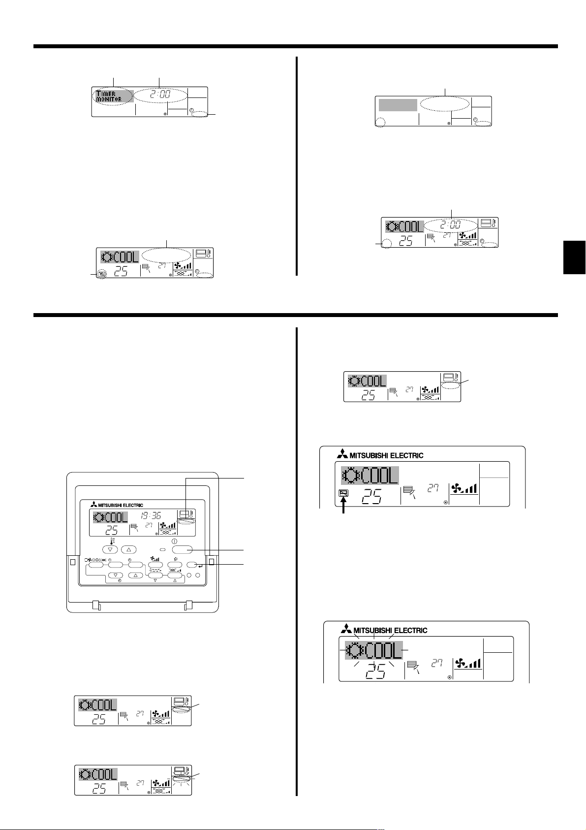
5.6. Ventillation
ss
sFor LOSSNAY combination
ss
5.6.1. For Wired Remote-controller
● To run the ventilator together with the indoor unit:
■ Press the ON/OFF button 1.
• The Vent indication appears on the screen (at 8). The ventilator will
now automatically operate whenever the indoor unit is running.
● To run the ventilator independently:
■ Press the Mode button 2 until appears on the display. This will
cause the ventilator to start.
● To change the ventilator force:
■ Press the Ventilation button 8 as necessary.
• Each press toggles the setting, as shown below.
▲
▲
Low High
<How to Set the Weekly Timer>
1. Be sure that you are at a standard control screen, and that the weekly
timer indicator 1 is shown in the display.
2. Press the Timer Menu button B, so that the “Set Up” appears on the
screen (at 2). (Note that each press of the button toggles the display
between “Set Up” and “Monitor”.)
3. Press the Timer On/Off (Set Day) button 9 to set the day. Each press
advances the display at 3 to the next setting, in the following sequence:
“Sun Mon Tues Wed Thurs Fri Sat” → “Sun” → ... → “Fri” → “Sat” → “Sun
Mon Tues Wed Thurs Fri Sat”...
4. Press the or Operation button (7 or 8) as necessary to select the
appropriate operation number (1 to 8) 4.
* Your inputs at Steps 3 and 4 will select one of the cells from the matrix
illustrated below.
(The remote-controller display at left shows how the display would
appear when setting Operation 1 for Sunday to the values indicated
below.)
Setup Matrix
Op No. Sunday Monday … Saturday
• 8:30
• ON
No. 1
• 23 °C
• 10:00
No. 2
• OFF
…
No. 8
<Operation 1 settings for Sunday>
Start the air conditioner at 8:30, with
the temperature set to 23 °C.
Note:
By setting the day to “Sun Mon Tues Wed Thurs Fri Sat”, you can set the same
operation to be carried out at the same time every day.
(Example: Operation 2 above, which is the same for all days of the week.)
<Setting the Weekly Timer>
Shows the time
setting
• 10:00
• OFF
▲
5
SUN
˚C
• 10:00
• OFF
• 10:00
• OFF
▲
<Operation 2 settings for every day>
Turn off the air conditioner at 10:00.
Shows the selected operation (ON or OFF)
6
* Does not appear if operation is not set.
ON
WEEKLY
Shows the temperature setting
7
* Does not appear if temperature is not
set.
6
6. Timer
5. Press the appropriate Set Time button A as necessary to set the
desired time (at 5).
* As you hold the button down, the time first increments in minute inter-
vals, then in ten-minute intervals, and then in one-hour intervals.
6. Press the ON/OFF button 1 to select the desired operation (ON or
OFF), at 6.
* Each press changes the next setting, in the following sequence:
No display (no setting) → “ON” → “OFF”
7. Press the appropriate Set Temperature button 3 to set the desired
temperature (at 7).
* Each press changes the setting, in the following sequence: No
display (no setting) ⇔ 24 ⇔ 25 ⇔ ... ⇔ 29 ⇔ 30 ⇔ 12 ⇔ ... ⇔ 23
⇔ No display.
(Available range: The range for the setting is 12 °C to 30 °C. The
actual range over which the temperature can be controlled, however, will vary according to the type of the connected unit.)
8. After making the appropriate settings at Steps 5, 6 and 7, press the
Filter button 4 to lock in the values.
To clear the currently set values for the selected operation, press and
quickly release the Check (Clear) button 0 once.
* The displayed time setting will change to “—:—”, and the On/Off
and temperature settings will all disappear.
(To clear all weekly timer settings at once, hold down the Check
(Clear) button 0 for two seconds or more. The display will begin
flashing, indicating that all settings have been cleared.)
Note:
Your new entries will be cancelled if you press the Mode (Return) button
2 before pressing the Filter
If you have set two or more different operations for exactly the same
time, only the operation with the highest Operation No. will be carried
out.
button 4.
6.1.2. Simple Timer
■ You can set the simple timer in any of three ways.
• Start time only:
The air conditioner starts when the set time has elapsed.
• Stop time only:
The air conditioner stops when the set time has elapsed.
• Start & stop times:
The air conditioner starts and stops at the respective elapsed times.
■ The simple timer (start and stop) can be set only once within a 72-hour
period.
The time setting is made in hour increments.
Note:
*1. Weekly Timer/Simple Timer/Auto Off Timer cannot be used at the same time.
*2. The simple timer will not operate when any of the following conditions is in
effect.
The timer is off; the system is in malfunction state; a test run is in progress;
the remote controller is undergoing self-check or remote controller check;
the user is in the process of selecting a function; the user is in the process
of setting the timer; the system is under central control. (Under these conditions, On/Off operation is prohibited.)
ONHr
AFTER
TEMP.
MENU
MONITOR/SET
BACK DAY
PAR-21MAA
CLOCK
ON/OFF
OPERATION
SIMPLE
ON/OFF
FILTER
CHECK
CLEAR
TEST
1
B
4
0
9. Repeat Steps 3 to 8 as necessary to fill as many of the available cells
as you wish.
10.Press the mode (Return) button 2 to return to the standard control
screen and complete the setting procedure.
11.To activate the timer, press the Timer On/Off button 9, so that the
“Timer Off” indication disappears from the screen. Be sure that the
“Timer Off” indication is no longer displayed.
* If there are no timer settings, the “Timer Off” indication will flash on
the screen.
<How to View the Weekly Timer Settings>
SUN
Timer Settings
9
˚C
ON
OFF
WEEKLY
1
8
TIMER
1.
Be sure that the weekly timer indicator is visible on the screen (at 1).
2. Press the Timer Menu button B so that “Monitor” is indicated on the
screen (at 8).
3. Press the Timer On/Off (Set Day) button 9 as necessary to select
the day you wish to view.
4. Press the or Operation button (7 or 8) as necessary to change
the timer operation shown on the display (at 9).
* Each press will advance to the next timer operation, in order of
time setting.
5. To close the monitor and return to the standard control screen, press
the Mode (Return) button 2.
<To Turn Off the Weekly Timer>
Press the Timer On/Off button 9 so that “Timer Off” appears at 0.
TIME SUN
˚C
WEEKLY
0
˚C
<To Turn On the Weekly Timer>
Press the Timer On/Off button 9 so that the “Timer Off” indication (at 0)
goes dark.
0
TIME SUN
˚C
˚C
WEEKLY
2A9
<How to Set the Simple Timer>
Timer Setting
2
4
AFTER
ONHr
SIMPLE
Action (On or Off)
3
* “— —” is displayed if there is no
setting.
1
1. Be sure that you are at a standard control screen, and that the simple
timer indicator is visible in the display (at 1).
When something other than the Simple Timer is displayed, set it to
SIMPLE TIMER using the function selection of remote controller (see
8.[4]–3 (3)) timer function setting.
2. Press the Timer Menu button B, so that the “Set Up” appears on the
screen (at 2). (Note that each press of the button toggles the display
between “Set Up” and “Monitor”.)
3. Press the ON/OFF button 1 to display the current ON or OFF simple
timer setting. Press the button once to display the time remaining to ON,
and then again to display the time remaining to OFF. (The ON/OFF
indication appears at 3).
•“ON” timer:
The air conditioner will start operation when the specified number of
hours has elapsed.
•“OFF” timer:
The air conditioner will stop operation when the specified number of
hours has elapsed.
4. With “ON” or “OFF” showing at 3: Press the appropriate Set Time button
A as necessary to set the hours to ON (if “ON” is displayed) or the hours
to OFF (if “OFF” is displayed) at 4.
• Available Range: 1 to 72 hours
5. To set both the ON and OFF times, repeat Steps 3 and 4.
* Note that ON and OFF times cannot be set to the same value.
6. To clear the current ON or OFF setting: Display the ON or OFF setting
(see step 3) and then press the Check (Clear) button 0 so that the time
setting clears to “—” at 4. (If you want to use only an ON setting or only
an OFF setting, be sure that the setting you do not wish to use is shown
as “—”.)
7

6. Timer
˚C
˚C
OFFHrAFTER
SIMPLE
˚C
˚C
SIMPLE
7. After completing steps 3 to 6 above, press the Filter button 4 to lock
in the value.
Note:
Your new settings will be cancelled if you press the Mode (Return) button 2
before pressing the Filter
button 4.
8. Press the Mode (Return) button 2 to return to the standard control
screen.
9. Press the Timer On/Off button 9 to start the timer countdown. When the
timer is running, the timer value is visible on the display. Be sure that the
timer value is visible and appropriate.
<Viewing the Current Simple Timer Settings>
Timer Setting
5
6
TIMER ON
OFFHrAFTER
SIMPLE
1
1. Be sure that the simple timer indicator is visible on the screen (at 1).
2. Press the Timer Menu button B, so that the “Monitor” appears on the
screen (at 5).
• If the ON or OFF simple timer is running, the current timer value will
appear at 6.
• If ON and OFF values have both been set, the two values appear
alternately.
3. Press the Mode (Return) button 2 to close the monitor display and return
to the standard control screen.
<To Turn Off the Simple Timer...>
Press the Timer On/Off button 9 so that the timer setting no longer appears on the screen (at 7).
7
Example 2:
Start the timer, with OFF time is sooner than ON time
ON Setting: 5 hours
OFF Setting: 2 hours
At Timer Start
Display shows the timer’s OFF setting (hours
▲
ONHr
AFTER
▲
remaining to OFF).
At 2 hours after timer start
Display changes to show the timer’s ON setting
SIMPLE
(hours remaining to ON).
The time displayed is ON setting (5 hours) –
OFF setting (2 hours) = 3 hours.
At 5 hours after timer start
The air conditioner comes on, and will continue
to run until someone turns it off.
6.1.3. Auto Off Timer
■ This timer begins countdown when the air conditioner starts, and shuts
the air conditioner off when the set time has elapsed.
■ Available settings run from 30 minutes to 4 hours, in 30-minute intervals.
Note:
*1. Weekly Timer/Simple Timer/Auto Off Timer cannot be used at the same time.
*2. The Auto Off timer will not operate when any of the following conditions is
in effect.
The timer is off; the system is in malfunction state; a test run is in progress;
the remote controller is undergoing self-check or remote controller check;
the user is in the process of selecting a function; the user is in the process
of setting the timer; the system is under central control. (Under these conditions, On/Off operation is prohibited.)
˚C
˚C
SIMPLE
<To Turn On the Simple Timer...>
Press the Timer On/Off button 9 so that the timer setting becomes visible
at 7.
˚C
7
ONHr
AFTER
˚C
SIMPLE
Examples
If ON and OFF times have both been set at the simple timer, operation and
display are as indicated below.
Example 1:
Start the timer, with ON time set sooner than OFF time
ON Setting: 3 hours
OFF Setting: 7 hours
ONHr
AFTER
▲
OFFHrAFTER
˚C
˚C
▲
At Timer Start
SIMPLE
Display shows the timer’s ON setting (hours
remaining to ON).
At 3 hours after timer start
Display changes to show the timer’s OFF set-
SIMPLE
ting (hours remaining to OFF).
The time displayed is OFF setting (7 hours) –
ON setting (3 hours) = 4 hours.
At 7 hours after timer start
The air conditioner goes off, and will remain off
SIMPLE
until someone restarts it.
AFTER OFF
OPERATION
AUTO OFF
ON/OFF
FILTER
CHECK
CLEAR
TEST
B
4
TEMP.
MENU
MONITOR/SET
BACK DAY
PAR-21MAA
CLOCK
ON/OFF
2A9
<How to Set the Auto Off Timer>
Timer Setting
2
3
AFTER OFF
AUTO OFF
1
1. Be sure that you are at a standard control screen, and that the Auto Off
timer indicator is visible in the display (at 1).
When something other than the Auto Off Timer is displayed, set it to
AUTO OFF TIMER using the function selection of remote controller (see
8.[4]–3 (3)) timer function setting.
2. Hold down the Timer Menu button B for 3 seconds, so that the “Set Up”
appears on the screen (at 2).
(Note that each press of the button toggles the display between “Set Up”
and “Monitor”.)
3. Press the appropriate Set Time button A as necessary to set the OFF
time (at 3).
4. Press the Filter button 4 to lock in the setting.
Note:
Your entry will be cancelled if you press the Mode (Return) button 2 before
pressing the Filter
button 4.
5. Press the Mode (Return) button 2 to complete the setting procedure and
return to the standard control screen.
6. If the air conditioner is already running, the timer starts countdown
immediately. Be sure to check that the timer setting appears cor-
rectly on the display.
8
6. Timer
AUTO OFF
7
<Checking the Current Auto Off Timer Setting>
Timer Setting
TIMER
AFTER
5
OFF
AUTO OFF
1
4
1. Be sure that the “Auto Off” is visible on the screen (at 1).
2. Hold down the Timer Menu button B for 3 seconds, so that “Monitor” is
indicated on the screen (at 4).
• The timer remaining to shutdown appears at 5.
3. To close the monitor and return to the standard control screen, press the
Mode (Return) button 2.
<To Turn Off the Auto Off Timer...>
● Hold down the Timer On/Off button 9 for 3 seconds, so that “Timer Off”
appears (at 6) and the timer value (at 7) disappears.
7
˚C
AUTO OFF
6
˚C
7. Other Functions
7.1. Locking the Remote Controller Buttons (Operation
function limit controller)
■ If you wish, you can lock the remote controller buttons. You can use the
Function Selection of remote controller to select which type of lock to use.
(For information about selecting the lock type, see section 8, item [4]–2
(1)).
Specifically, you can use either of the following two lock types.
1Lock All Buttons:
Locks all of the buttons on the remote controller.
2Lock All Except ON/OFF:
Locks all buttons other than the ON/OFF button.
Note:
The “Locked” indicator appears on the screen to indicate that buttons are currently locked.
1
Lock Indicator
● Alternatively, turn off the air conditioner itself. The timer value (at 7) will
disappear from the screen.
<To Turn On the Auto Off Timer...>
● Hold down the Timer On/Off button 9 for 3 seconds. The “Timer Off”
indication disappears (at 6), and the timer setting comes on the display
(at 7).
● Alternatively, turn on the air conditioner. The timer value will appear at 7.
7
AFTER OFF
˚C
AUTO OFF
6
˚C
<How to Unlock the Buttons>
1. While holding down the Filter button 4, press and hold down the ON/OFF
button 1 for 2 seconds—so that the “Locked” indication disappears from
the screen (at 1).
˚C
˚C
1
7.2. Other indications
7.2.1. Centrally Controlled
˚C
˚C
TIME SUN
FUNCTION
˚C
TEMP.
˚C
ON/OFF
1
MENU
MONITOR/SET
BACK DAY
PAR-21MAA
CLOCK
ON/OFF
OPERATION
FILTER
CHECK
CLEAR
TEST
4
<How to Lock the Buttons>
1. While holding down the Filter button 4, press and hold down the ON/OFF
button 1 for 2 seconds. The “Locked” indication appears on the screen
(at 1), indicating that the lock is now engaged.
* If locking has been disabled in Function Selection of remote controller,
the screen will display the “Not Available” message when you press the
buttons as described above.
˚C
˚C
1
FUNCTION
• If you press a locked button, the “Locked” indication (at 1) will blink
on the display.
1
FUNCTION
˚C
˚C
TEMP.
ON/OFF
● Displayed when operation is controlled by central controller, etc.
Restricted operations are shown below.
• ON/OFF (including timer operation)
• Operation mode
• Set temperature
Note:
May also be individually restricted.
7.2.2. Flashing Mode Indicator
˚C
TEMP.
■ When flashes continuously
Displayed when another indoor unit connected to the outdoor unit is
already operating in a different operation mode.
Match with the operation mode of the other indoor unit.
■ When mode switched after display flashes
Displayed when operation mode is restricted for each season by central
controller, etc.
Use another operation mode.
˚C
ON/OFF
9
7. Other Functions
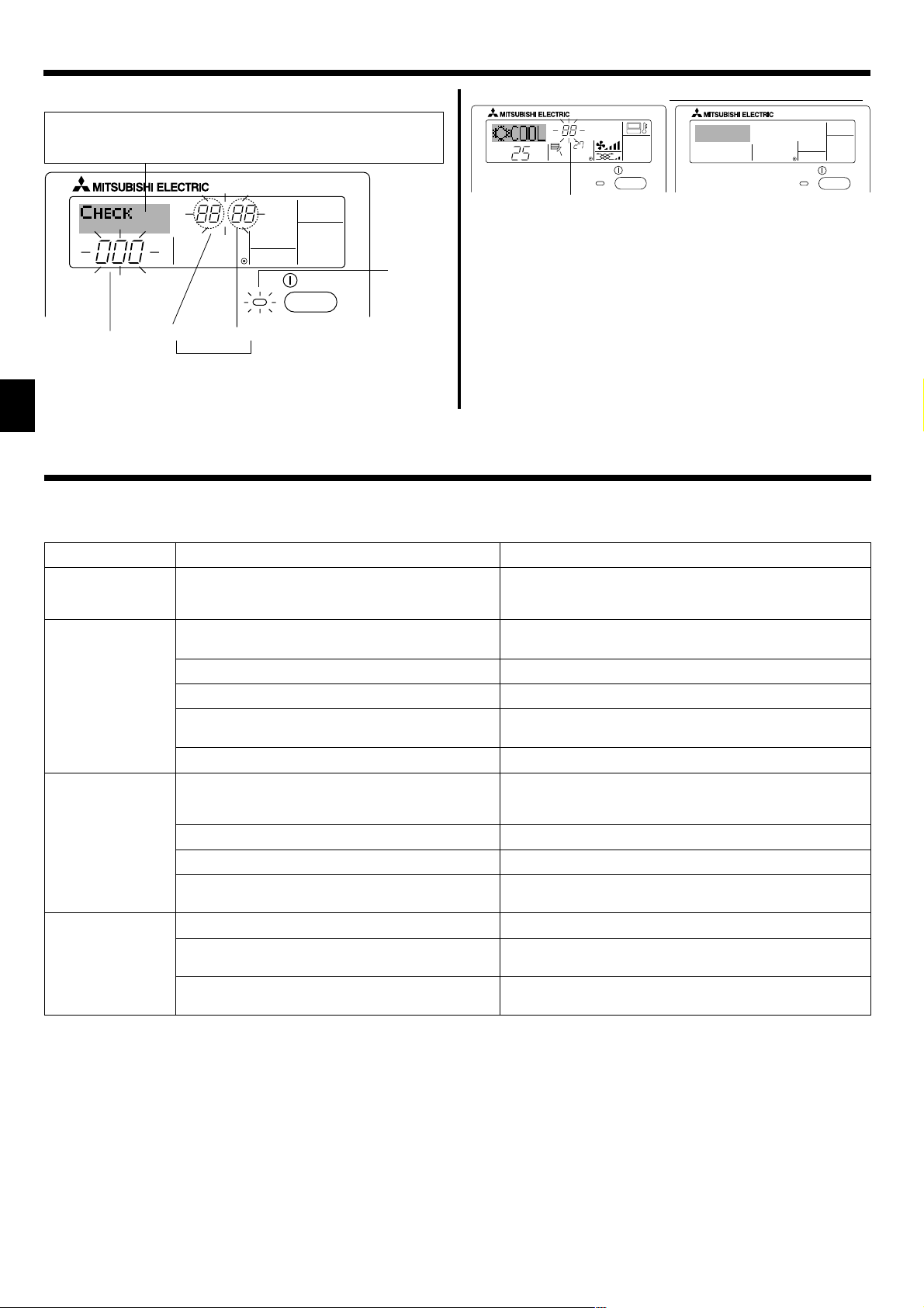
7.2.3. Error Codes indication
If you have entered contact number to be called in the event of a problem, the screen displays this number. (You can set this up under Function Selection of remote controller. For information, refer to section 8.)
ERROR CODE
˚C
˚C
ON/OFF
When the Check button is pressed:
CALL:XXXX
XXX:XXX
ON/OFF
Error Code
ERROR CODE
● If the ON lamp and error code are both flashing: This means that the air
conditioner is out of order and operation has been stopped (and cannot
resume). Take note of the indicated unit number and error code, then
switch off the power to the air conditioner and call your dealer or servicer.
● If only the error code is flashing (while the ON lamp remains lit): Opera-
ON/OFF
ON lamp
(Flashing)
tion is continuing, but there may be a problem with the system. In this
case, you should note down the error code and then call your dealer or
servicer for advice.
* If you have entered contact number to be called in the event of a
problem, push the Check button to display it on the screen. (You can
set this up under Function Selection of remote controller. For infor-
Indoor Unit’s
Refrigerant
Address
Error Code
Alternating
Display
Indoor Unit No.
mation, refer to section 8.)
8. Function Selection
Function selection of remote controller
The setting of the following remote controller functions can be changed using the remote controller function selection mode. Change the setting when
needed.
Item 1
1. Change Language
(“CHANGE
LANGUAGE”)
2. Function limit
(“FUNCTION
SELECTION”)
3. Mode selection
(“MODE SELECTION”)
4. Display change
(“DISP MODE
SETTING”)
Item 2
Language setting to display
(1) Operation function limit setting (operation lock) (“LOCKING
FUNCTION”)
(2) Use of automatic mode setting (“SELECT AUTO MODE”)
(3) Temperature range limit setting (“LIMIT TEMP FUNCTION”)
(4) Use of automatic filter elevation panel up/down operation
mode setting
(5) Use of fixed airflow direction mode setting
(1) Remote controller main/sub setting (“CONTROLLER MAIN/
SUB”)
(2) Use of clock setting (“CLOCK”)
(3) Timer function setting (“WEEKLY TIMER”)
(4) Contact number setting for error situation (“CALL.”)
(1) Temperature display °C/°F setting (“TEMP MODE °C/°F”)
(2) Suction air temperature display setting (“ROOM TEMP DISP
SELECT”)
(3) Automatic cooling/heating display setting (“AUTO MODE
DISP C/H”)
Item 3 (Setting content)
• Display in multiple languages is possible
• Setting the range of operation limit (operation lock)
• Setting the use or non-use of “automatic” operation mode
• Setting the temperature adjustable range (maximum, minimum)
(For this model, this function is not available.)
(For this model, this function is not available.)
• Selecting main or sub remote controller
* When two remote controllers are connected to one group, one controller
must be set to sub.
• Setting the use or non-use of clock function
• Setting the timer type
• Contact number display in case of error
• Setting the telephone number
• Setting the temperature unit (°C or °F) to display
• Setting the use or non-use of the display of indoor (suction) air tempera-
ture
• Setting the use or non-use of the display of “Cooling” or “Heating” display
during operation with automatic mode
10
8. Function Selection
OFF
on1
OFF
ON
ON
OFF
OFF
PAR-21MAA
ON/OFF
FILTER
CHECK
OPERATION
CLEAR
TEST
TEMP.
MENU
BACK DAY
MONITOR/SET
CLOCK
ON/OFF
F
E
G
C
D
H
B
A
I
G
G
G
G
G
G
E
E
G
G
G
G
G
E
G
E
G
G
G
G
G
G
D
D
D
D
D
D
D
D
D
D
D
D
D
D
D
D
D
D
D
D
D
D
D
D
D
D
D
D
D
D
English
Germany
Spanish
Russian
Italy
Chinese
French
Japanese
*
*
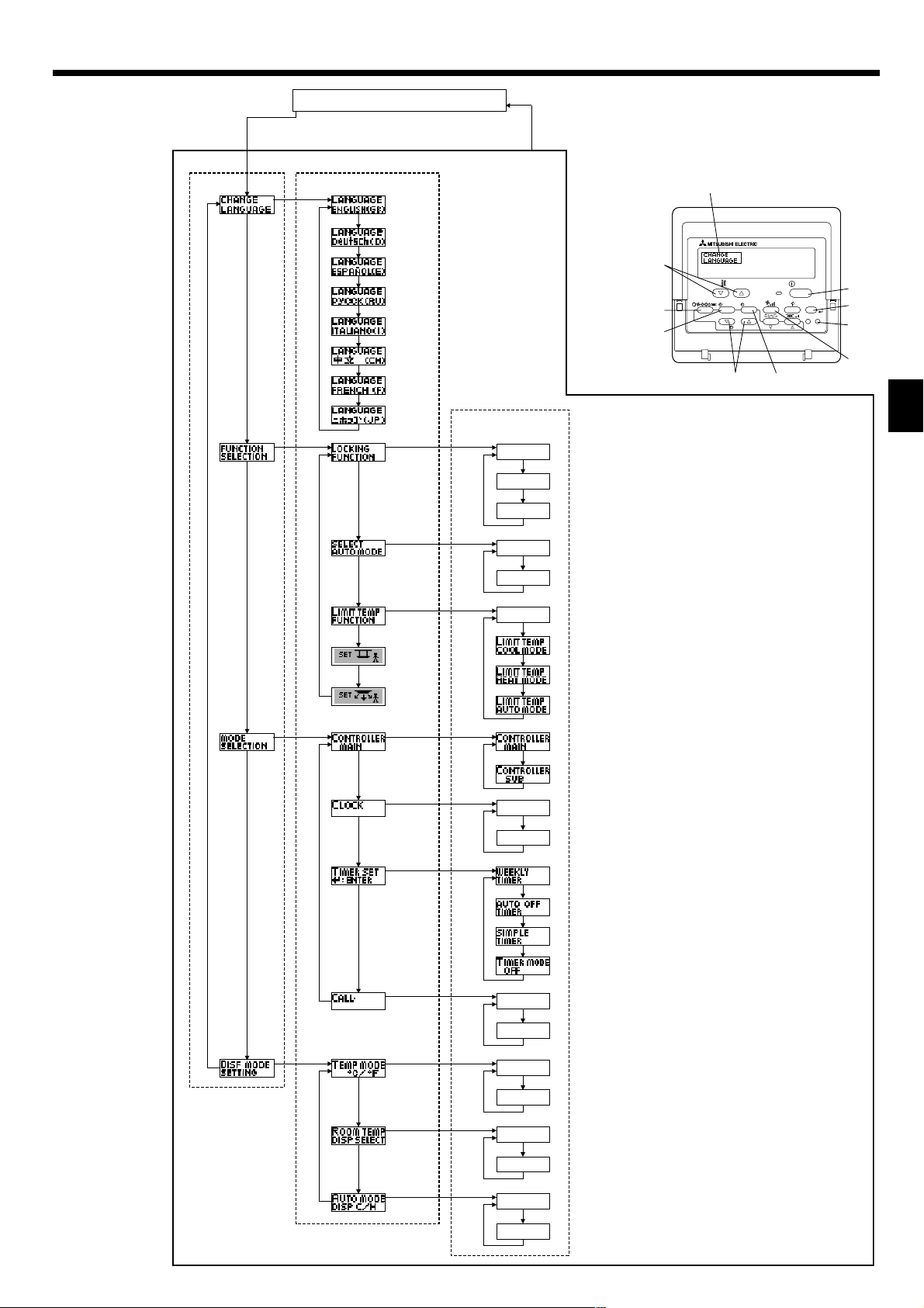
[Function selection flowchart]
Setting language (English)
Item1 Item2
Change
Language
Function
selection
Mode
selection
Normal display
(Display when the air condition is not running)
Hold down the E button and press the D button for 2 seconds.
Remote controller function selection mode
Item3
Hold down the E button and press the D button for 2 seconds.
E Press the operation mode button.
G Press the TIMER MENU button.
D Press the TIMER ON/OFF button.
Dot display
Operation lock setting is not used.
(Initial setting value)
Operation lock setting is except On/Off button.
on2
OFF
Operation lock setting is All buttons.
The automatic mode is displayed when the operation mode is
selected. (Initial setting value)
The automatic mode is not displayed when the operation mode
is selected.
The temperature range limit is not active. (Initial setting value)
The temperature range can be changed on cooling/dry mode.
The temperature range can be changed on heating mode.
The temperature range can be changed on automatic mode.
*) For this model, this function is not available.
The remote controller will be the main controller. (Initial setting value)
The remote controller will be the sub controller.
Display
mode setting
The clock function can be used. (Initial setting value)
The clock function can not be used.
Weekly timer can be used. (Initial setting value)
Auto off timer can be used.
OFF
CALL-
°C
°F
ON
ON
OFF
Simple timer can be used.
Timer mode can not be used.
The set contact numbers are not displayed in case of error.
(Initial setting value)
The set contact numbers are displayed in case of error.
The temperature unit °C is used. (Initial setting value)
The temperature unit °F is used.
Room air temperature is displayed. (Initial setting value)
Room air temperature is not displayed.
One of “Automatic cooling” and “Automatic heating” is displayed
under the automatic mode is running. (Initial setting value)
Only “Automatic” is displayed under the automatic mode.
11
 Loading...