


SHOGUN SPORT
OWNER’S MANUAL
SHOGUN SPORT - EN-UK - 17MY OKWE17E1
Foreword
E09200106793
Thank you for selecting a MITSUBISHI MOTORS product as your new vehicle.
This owner’s manual will add to your understanding and full enjoyment of the many fine features of this vehicle.
It contains information prepared to acquaint you with the proper way to operate and maintain your vehicle for the utmost in driving pleasure.
MITSUBISHI MOTORS CORPORATION reserves the right to make changes in design and specifications and/or to make additions to or improvements in this product without obligation to install them on products previously manufactured.
It is an absolute requirement for the driver to strictly observe all laws and regulations concerning vehicles.
This owner’s manual has been written in compliance with such laws and regulations, but some of the contents may become contradictory with later amendment of the laws and regulations.
If your vehicle is equipped with any locally produced part, the operating procedure, specifications, maintenance intervals and other contents found in this owner’s manual may not sometimes apply to it.
Throughout this owner’s manual the words WARNING and
CAUTION appear.
These serve as reminders to be especially careful. Failure to follow instructions could result in personal injury or damage to your vehicle.
Indicates a strong possibility of severe personal injury or death if instructions are not followed.
Means hazards or unsafe practices that could cause minor personal injury or damage to your vehicle.
You will see another important symbol:
NOTE: gives helpful information.
*: indicates optional equipment.
It may differ according to the sales classification; refer to the sales catalogue.
Abbreviations used in this owner’s manual:
LHD: Left-Hand Drive
RHD: Right-Hand Drive
M/T: Manual Transmission
A/T: Automatic Transmission
This manual explains operation of LHD and RHD vehicles. Illustrations represent LHD operation. Depending on the item, however, RHD illustrations may also appear.
This vehicle is manufactured by Mitsubishi Motors (Thailand) Co, Ltd. in Thailand under license from Mitsubishi Motors Corporation.
©2016 Mitsubishi Motors Corporation

Foreword – Diesel Engines
During very cold weather some diesel-powered engines may experience difficulties with starting and initial running. These problems arise from the formation of wax crystals, which block fuel filters and/or fuel lines. All diesel fuel contains wax. It is considered an important diesel component because of its high cetane value (a measure of the fuel’s resistance to premature combustion). Normally the wax remains liquid but when diesel fuel gets cold enough the wax starts to crystallize and solidify. If the temperature is sufficiently low, enough crystals will form to block the fuel filter and/or fuel lines, resulting in the engine becoming difficult to start and run until the fuel temperature increases sufficiently.
UK diesel is manufactured to the European standard BS EN 590 and the specification of the fuel supplied from refineries is changed during winter months (Circa: 16th November to 15th March) in order to improve the cold weather performance properties of the fuel. The UK is in a zone that specifies that diesel remains free of wax crystals down to -15 Centigrade (known as the cold filter plugging point test CFPP).
With sustained temperatures below this level, particularly in exposed areas or when a vehicle is left idle for several days, blocking of filters and/or fuel lines may occur resulting in the engine becoming difficult to start and run until the fuel temperature increases sufficiently.
There are a number of practical measures that can be taken to avoid or reduce problems, including the following:
•It may be advisable to sit in the vehicle with engine running for several minutes before moving off in order to aid build up to working temperature.
•If possible, park your vehicle in a garage overnight or in a more sheltered area near a building.
•Avoid parking the vehicle with the front facing into the wind.
•If it is impossible to move the vehicle due to snow, try to run the engine daily in order to maintain movement in the fuel system and generate heat.
Under no circumstances should heat that involves a naked flame or other potential sources of ignition, be applied to any of the fuel system components.
If you are aware that you will be operating your vehicle in conditions of circa: -10 Centigrade or below on a regular basis we recommend the fitment of a fuel line heater. Your local Mitsubishi Motors dealership will be able to assist you with this.
Table of contents
Overview/Quick guide |
|
1 |
|
|
|
General information |
2 |
|
|
|
|
Locking and unlocking |
3 |
|
|
|
|
Seat and seat belts |
4 |
|
|
|
|
Instruments and controls |
5 |
|
|
|
|
Starting and driving |
6 |
|
|
|
|
For pleasant driving |
7 |
|
|
|
|
For emergencies |
8 |
|
|
|
|
Vehicle care |
9 |
|
|
|
|
Maintenance |
10 |
|
|
|
|
Specifications |
11 |
|
|
|
|
Alphabetical index |
12 |
Instruments and Controls (Driver’s area)
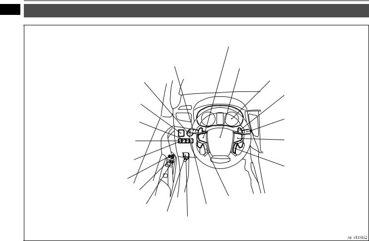
1 Instruments and Controls (Driver’s area)
E08500101710
Combination headlamps and dipper switch P.5-57 Turn-signal lever P.5-62
Front fog lamp switch* P.5-63 Rear fog lamp switch* P.5-64 Headlamp washer switch* P.5-69
Engine switch* P.6-18
Multi Around Monitor operation switch* P.6-134 Audio remote control switches* P.7-34
Horn switch P.5-70
Supplemental restraint system (SRS) - airbag (for driver’s seat) P.4-30, 4-35
Instruments P.5-2
Outside rear-view mirrors switch P.6-15
Sonar switch* P.6-123
Forward Collision Mitigation System (FCM) and Ultrasonic misacceleration Mitigation System (UMS) ON/OFF switch* P.6-107
Headlamp levelling switch* P.5-61
Lock switch P.3-25
Central door lock switch P.3-16
Electric window control switch P.3-24
Fuel tank filler door release lever
P.2-3
Shift paddles* P.6-42
Wiper and washer switch P.5-64
Rear wiper and washer switch
P.5-68
Cruise control switch* P.6-85, 6-94
Adaptive Cruise Control System (ACC)* P.6-90
Adaptive Cruise Control System (ACC)*
P.6-90
Multi information display switch* P.5-4
Bluetooth® 2.0 interface* P.7-60
Active stability control (ASC) OFF switch* P.6-83
Bonnet release lever P.10-4
1-1 |
Overview/Quick guide |
|
Instruments and Controls |
|||
|
|
|
|
|
1 |
||||
Instruments and Controls |
|
|
||
|
|
|
||
|
E08500101723 |
|||
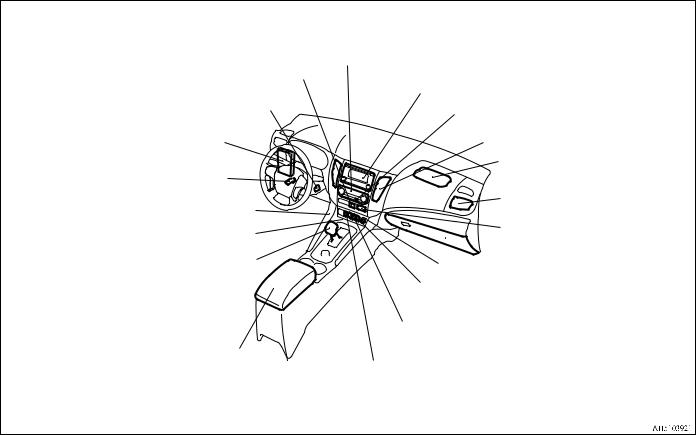
LHD
Air conditioner* P.7-2 Front cooler* P.7-6
Hazard warning flasher switch P. 5-63
Audio* P.7-22
Smartphone Link Display Audio*, Mitsubishi Multi-Commu- nication System*, DISPLAY AUDIO*
Refer to the separate owner’s manual
Ignition switch* P.6-17
Fuses P.10-22
Steering wheel height and reach adjustment lever P.6-13
Key slot (8A/T)* P.6-27
Key slot (M/T, 5A/T)* P.6-27
Rear window demister switch P.5-69
Centre ventilators P.7-3
Supplemental restraint system (SRS) - airbag (for front passenger’s seat) P.4-30, 4-35
Side ventilators P.7-3
Front passenger’s airbag indicator*
P.4-31, 4-33  Glove box P.7-91
Gearshift lever* P.6-30
Selector lever* P.6-32
Floor console box P.7-92 Accessory socket* P.7-87
USB input terminal (A/T)* P.7-80 HDMI terminal (A/T)* P. 7-84
Cigarette lighter* P.7-87 Accessory socket* P.7-87
USB input terminal (M/T)* P.7-80 HDMI terminal (M/T)* P.7-84 Rear fan switch (8A/T)* P.7-21
Blind Spot Warning switch* P.6-114 Rear fan switch (M/T, 5A/T)* P.7-21
Rear differential lock switch* P.6-61
Overview/Quick guide |
1-2 |

Instruments and Controls
1 RHD
Audio* P.7-22 |
Rear window demister switch P.5-69 |
|
DISPLAY AUDIO*, Mitsubishi Multi |
||
|
||
Entertainment System* |
Front passenger’s airbag indicator* P.4-31, 4-33 |
|
Refer to the separate owner’s manual |
||
Cigarette lighter* P.7-87 |
||
|
||
Air conditioner* P.7-2 |
Accessory socket* P.7-87 |
|
Front cooler* P.7-6 |
Steering wheel height and reach adjustment lever |
|
Hazard warning flasher switch P. 5-63 |
P.6-13 |
Centre ventilators P.7-3 |
Ignition switch* P.6-17 |
|
|
||
Supplemental restraint system (SRS) - airbag |
|
|
(for front passenger’s seat) P.4-30, 4-35 |
Key slot (8A/T)* P.6-27 |
|
Side ventilators P.7-3 |
||
|
||
|
USB input terminal (M/T)* P.7-80 |
|
Fuses P.10-22 |
HDMI terminal (M/T)* P. 7-84 |
|
Rear fan switch (8A/T)* P.7-21 |
||
|
||
|
Gearshift lever* P.6-30 |
|
Glove box P.7-91 |
Selector lever* P.6-32 |
|
|
|
Floor console box P.7-92 |
|
Rear differential lock switch* P.6-61 |
Accessory socket* P.7-87 |
|
HDMI terminal (A/T)* P.7-84 |
||
|
||
Key slot (M/T, 5A/T)* P.6-27 |
USB input terminal (A/T)* P.7-80 |
Blind Spot Warning switch* P.6-114
Rear fan switch (M/T, 5A/T)* P.7-21
1-3 Overview/Quick guide
Instruments and Controls
|
|
|
|
1 |
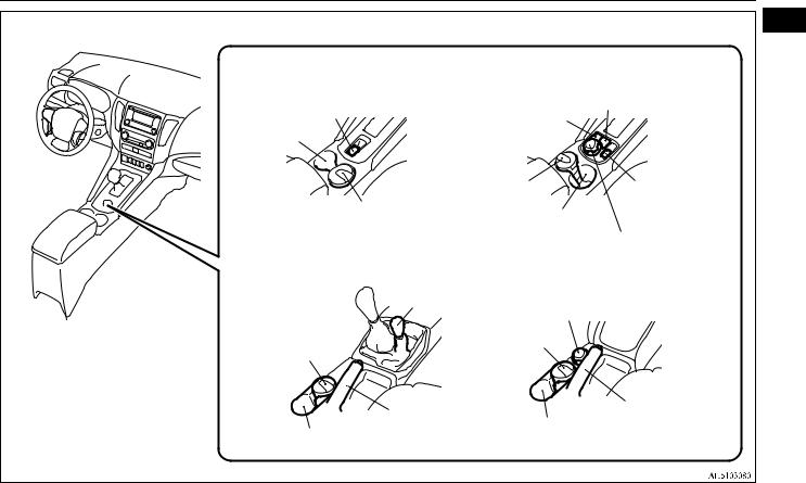
8A/T 2WD |
|
8A/T 4WD |
|
|
|
|
|
Off Road mode |
|
Electric parking brake switch P.6-8 |
|
Hill Descent Control |
switch* P.6-60 |
|
|
|
|
|
|
Cup holder P.7-94 |
|
switch* P.6-78 |
|
|
|
|
|
|
|
|
|
Ashtray* P.7-86 |
Electric parking |
|
|
|
brake switch |
|
|
Ashtray* P.7-86 |
Cup holder P.7-94 |
P.6-8 |
|
|
|
|
|
|
|
|
|
|
Super select 4WD II P.6-50 |
|
5M/T |
|
6M/T, 5A/T |
|
|
|
Super select 4WD* |
|
|
|
|
P.6-46 |
Super select 4WD II* P.6-50 |
|
|
|
|
|
||
Ashtray* P.7-86 |
|
Ashtray* P.7-86 |
|
|
|
|
|
|
|
|
Lever type |
|
Lever type |
|
|
|
parking brake |
|
|
|
parking brake |
|
||
|
lever P.6-6 |
|
||
|
lever P.6-6 |
Cup holder P.7-94 |
|
|
Cup holder P.7-94 |
|
|
||
|
|
|
|
|
|
|
Overview/Quick guide |
1-4 |
|

Interior
1 |
Interior |
|
|
|
|
|
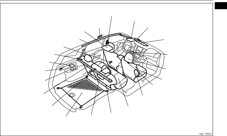
E08500201476 |
|
7 persons |
Seat belts P.4-14 |
Front room & map lamps P.7-88, 7-90, 10-29 |
|
|
Adjustable seat belt anchor P.4-16 |
|
|
|
Sunglasses holder* P.7-91, 7-93 |
|
|
Rear entertainment system* |
||
|
Sunroof* P.3-26 |
||
|
Refer to the separate owner’s manual |
Inside rear-view mirror P.6-13 |
|
|
Door courtesy lamps P.7-88, 7-91 |
||
|
Sun visors P.7-85 |
||
|
Supplemental restraint system (SRS)- |
|
|
|
|
Card holder P.7-85 |
|
|
curtain airbag* P.4-30, 4-38 |
|
Vanity mirror P.7-86 |
|
Rear personal lamps P.7-88, 7-90, 10-29 |
|
|
|
Rear cooler P.7-20 |
|
Supplemental restraint system |
|
Tether anchorage locations* P.4-26 |
|
(SRS) -driver’s knee airbag* |
|
|
|
P.4-30, 4-35 |
|
Luggage compartment lamp |
|
|
|
P.7-88, 7-90, 10-29 |
|
Head restraints P.4-7 |
|
Accessory socket P.7-87 |
|
|
|
|
|
Front seats P.4-4 |
Cup holder P.7-95
Tether anchorage locations* P.4-26
Armrest P.4-5
Cup holder P.7-94
Supplemental restraint system (SRS) -side airbag (for front seat)* P.4-30, 4-38
Convenient hook P.7-97
Second seats P.4-5
Child restraint system with ISOFIX mountings* P.4-26
Lower anchorage location* P.4-26
Third seats P.4-6
Tether anchorage locations* P.4-26
1-5 Overview/Quick guide
|
|
|
Interior |
5 persons |
Seat belts P.4-14 |
|
1 |
|
|
Front room & map lamps P.7-88, 7-90, 10-29 |
|
|
Adjustable seat belt anchor P.4-16 |
Sunglasses holder* P.7-91, 7-93 |
|
|
Rear personal lamps |
Sunroof* P.3-26 |
|
|
Inside rear-view mirror P.6-13 |
||
Rear entertainment system* |
P.7-88, 7-90, 10-29 |
|
|
Refer to the separate owner’s manual |
|
|
|
Supplemental restraint system (SRS)- |
|
Sun visors P.7-85 |
|
curtain airbag* P.4-30, 4-38 |
|
|
Card holder P.7-85 |
Door courtesy lamps P.7-88, 7-91 |
|
|
Vanity mirror P.7-86 |
|
|
|
|
Tether anchorage locations* P.4-26 |
|
|
Supplemental restraint system |
|
|
|
(SRS) -driver’s knee airbag * |
Luggage compartment lamp |
|
|
P.4-30, 4-35 |
P.7-88, 7-90, 10-29 |
|
|
|
Accessory socket P.7-87 |
|
|
Head restraints P.4-7 |
|
|
|
|
Cup holder P.7-95 |
|
|
Front seats P.4-4 |
|
|
|
|
|
|
|
Convenient hook P.7-97 |
Cargo area cover* P.7-95 |
|
|
Supplemental restraint system (SRS) -side |
|
|
|
airbag (for front seat)* P.4-30, 4-38 |
Tether anchorage locations* P.4-26 |
|
|
Second seats P.4-5 |
|
|
Child restraint system with ISOFIX mountings* P.4-26 |
|
|
|
|
Lower anchorage location* P.4-26 |
Luggage net* P.7-98 |
Armrest P.4-5 |
Tether anchorage locations* P.4-26 |
|
Cup holder P.7-94 |
|
|
|
|
|
|
|
Overview/Quick guide |
1-6 |
Luggage area
1 Luggage area
E08500301217
Tools P.8-7 |
Jack P.8-7 |
Luggage hooks P.7-97
Luggage floor boxes* P.7-91, 7-93 Warning triangle*
Fire extinguisher* Warning triangle* First-aid kit*
1-7 Overview/Quick guide

|
Exterior - front |
|||
|
|
|
|
|
1 |
||||
Exterior - front |
|
|
||
|
|
|
|
|
|
|
E08500401928 |
|
|
Sunroof* P.3-26 |
Outside rear-view mirrors P.6-14 |
|
Roof antenna* P.7-57 |
|
Side-view camera* P.6-133 |
|
Wiper and washers P.5-64, 10-20 |
|
Fuel tank filler door P.2-3 |
|
|
|
Locking and unlocking P.3-15, 3-16 |
|
Bonnet P.10-4 |
|
Keyless entry system P.3-4 |
|
|
Keyless operation system* P.3-7 |
|
|
Engine compartment P.10-2, 11-11 |
|
|
|
|
Security alarm system* P.3-20 |
|
|
|
|
|
|
|
|
Side turn-signal lamps (on outside rear- |
|
Headlamp washer* P.5-69 |
|
view mirror)* P.5-62, 10-28 |
|
Forward Collision Mitigation System |
|
Side turn-signal lamps (on fender)* P.5-62, 10-28 |
|
(FCM) sensor* P.6-102 |
|
Blind Spot Warning Sensor* P.6-114 |
|
Front-view camera* P.6-133 |
|
|
|
|
Ultrasonic misacceleration Mitigation System sensor* P.6-112 |
|
|
Ultrasonic misacceleration Mitigation System sensor* P.6-112 |
|
|
|
|
Sensor system sensor* P.6-125 |
|
|
Sensor system sensor* P.6-125 |
|
|
|
|
|
|
|
Except for LED headlamp type |
LED headlamp type |
|
|
Headlamps P.5-57, 10-28, 10-29 |
|
Headlamps P. 5-57, 10-28 |
|
Front turn-signal lamps |
Front turn-signal lamps |
|
|
P.5-62, 10-28, 10-31 |
|
||
P.5-62, 10-28, 10-31 |
|
||
|
|
||
Position lamps |
Daytime running lamps |
|
|
P.5-57, |
P.5-59, 10-28 |
|
|
10-28, 10-30 |
Position lamps P.5-57, 10-28 |
|
|
Front fog lamps* |
|
Front fog lamps* |
|
P.5-63, 10-28, 10-32 |
|
|
|
Daytime running lamps* P.5-59, 10-28, 10-32 |
|
P.5-63, 10-28, 10-32 |
|
|
|
Overview/Quick guide |
1-8 |
Exterior - rear
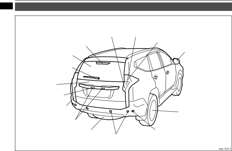
1 Exterior - rear
E08500401931
Reversing lamps P.10-28, 10-33 Rear turn-signal lamps P.5-62, 10-28, 10-33
High-mounted stop lamp P.10-28
Glass antenna* P.7-58
Rear wiper and washer P.5-68
Tailgate P.3-18
Rear-view camera* P.6-129, 6-133
Multi around monitor* P.6-133
Rear fog lamp (driver’s side)*
P.5-64, 10-28, 10-33
Licence plate lamp P.5-57, 10-28, 10-34
Spare wheel P.8-9
Tail and stop lamps P.5-57, 10-28, 10-33
Blind Spot Warning lamp* P.6-116
Tyre inflation pressures P.10-16 Changing tyres P.8-8
Tyre rotation P.10-18 Snow tyres P.10-19 Tyre chains P.10-19
Tyre pressure monitoring system (TPMS) P.6-117
Blind Spot Warning Sensor* P.6-114 Ultrasonic misacceleration Mitigation System sensor* P.6-112
Reversing sensor system sensor* P.6-122 Sensor system sensor* P.6-125
1-9 Overview/Quick guide
Quick guide
Quick guide |
Refer to “Keyless entry system” on page |
Driver’s or front passenger’s door lock/unlock |
1 |
3-4. |
|||
E08500500010 |
For vehicles equipped with the mirror retrac- |
switches |
|
|
|
|
|
Lock and unlock the doors |
tor switch, the outside rear-view mirrors can |
|
|
be folded and extended automatically if you |
|
|
|
E08500601438 |
press the LOCK switch (1) or UNLOCK |
|
|
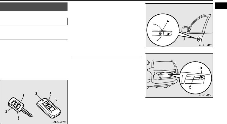
Keyless entry system |
switch (2). |
|
|
Refer to “Operation of the outside rear- |
|
|
|
|
|
|
|
Press the key switch, and all doors and the |
view mirrors” on page 3-4. |
|
|
|
|
|
|
tailgate will be locked or unlocked as desired. |
Keyless operation system* |
|
|
It is also possible to operate the outside rear- |
Tailgate switches |
|
|
view mirrors (Vehicles equipped with the |
|
|
|
|
|
|
|
mirror retractor switch). |
When you are carrying the keyless operation |
|
|
The key switch will operate within approxi- |
key and within the operating range, if you |
|
|
mately 4 m from the vehicle. |
press the driver’s or front passenger’s door |
|
|
|
switch (A), or the tailgate switch (B) (when |
|
|
Keyless entry key Keyless operation key |
locking) and the tailgate open switch (C) |
|
|
|
(when unlocking), the doors and the tailgate |
|
|
|
are locked/unlocked. |
|
|
|
The operating range is approximately 70 cm |
|
|
|
from the driver’s or front passenger’s door |
Refer to “keyless operation system” on |
|
|
switch and the tailgate switches. |
|
|
|
|
page 3-7. |
|
1- LOCK switch |
|
|
|
2- UNLOCK switch |
|
|
|
3- Indicator lamp |
|
|
|
Overview/Quick guide |
1-10 |

Quick guide
1 Around the driver’s seat |
1-Electric remote-controlled out- |
2-Engine switch* |
|
E08500801485 side rear-view mirrors |
|
|
|
[For vehicles equipped with the keyless oper- |
|
To adjust the mirror position |
ation system] |
|
|
If you are carrying the keyless operation key, |
|
|
you can start the engine. If you press the |
|
Except for vehicles |
engine switch without depressing the brake |
|
pedal (A/T) or the clutch pedal (M/T), you |
|
|
equipped with the mir- |
|
|
ror retractor switch |
can change the operation mode in the order of |
|
|
OFF, ACC, ON, OFF. |
|
Vehicles equipped with |
|
|
the mirror retractor |
|
|
switch |
|
L- Left outside mirror adjustment R- Right outside mirror adjustment 1- Up
2- Down
3- Right
4- Left
5- Mirror retractor switch
Refer “Outside rear-view mirrors” on page 6-14.
OFFThe indicator lamp on the engine switch turns off.
ACCThe indicator lamp on the engine switch illuminates orange.
ONThe indicator lamp on the engine switch illuminates green.
Refer “Engine switch” on page 6-18.
1-11 Overview/Quick guide

|
|
|
Quick guide |
||
3-Combination headlamps |
|
3-Turn-signal lever |
|
|
|
Type 2 |
1 |
||||
Rotate the switch to turn on the lamps.
Type 1
OFF All lamps off
Position, tail, licence plate, instrument panel lamps on
Headlamps and other lamps go on
OFF |
All lamps off |
With the ignition switch or the operation mode is in ON, headlamps, position, tail, licence plate and instrument panel lamps turn on
AUTO and off automatically in accordance with outside light level. All lamps turn off automatically when the ignition switch is turned to the “OFF” position or the operation mode is put in OFF.
Position, tail, licence plate and instrument panel lamps on
Headlamps and other lamps go on
Refer “Combination headlamps and dipper switch” on page 5-57.
The turn-signal lamps flash when the lever is operated.
1- |
Turn-signals |
2- |
Lane-change signals |
Refer “Turn-signal lever” on page 5-62. |
|
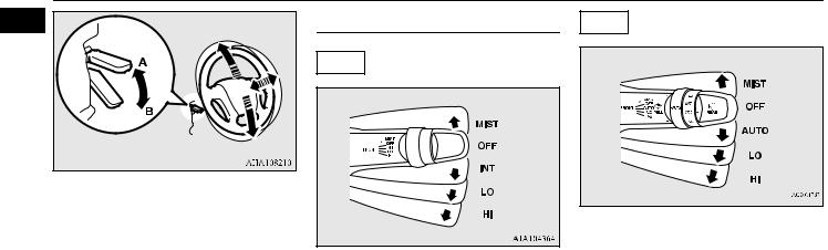
4-Steering wheel height and reach adjustment
1.Release the lever while holding the steering wheel up.
2.Adjust the steering wheel to the desired position.
3.Securely lock the steering wheel by pulling the lever fully upward.
Overview/Quick guide |
1-12 |
|
Quick guide |
|
1 |
5-Wiper and washer switch |
Type 2 |
|
Type 1 |
|
A- Locked
B- Release
Refer “Steering wheel height and reach adjustment” on page 6-13.
MISTMisting function
The wipers will operate once. OFFOff
INTIntermittent (Speed sensitive) LOSlow
HIFast
MISTMisting function
The wipers will operate once. OFFOff
AUTO- Auto-wiper control Rain sensor
The wipers will automatically operate depending on the degree of wetness on the windscreen.
Slow
Fast
The washer fluid will be sprayed onto the windscreen by pulling the lever towards you.
Refer to “Wiper and washer switch” on page 5-64.
1-13 Overview/Quick guide
|
|
|
|
Quick guide |
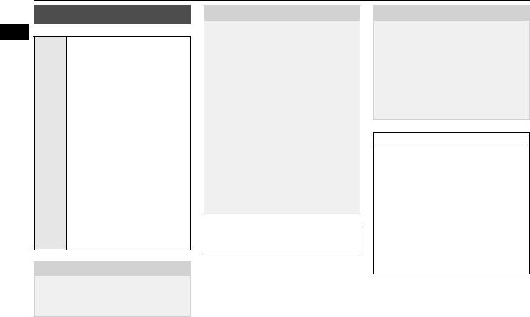
6-Electric window control |
7-Fuel tank filler door release |
LHD |
1 |
|
Press the switch down for opening the win- |
lever |
|
|
|
|
|
|
||
dow, and pull the switch for closing. |
Open the fuel tank filler door. |
|
|
|
|
|
The fuel tank filler is located on the rear left |
|
|
Driver’s switch |
Driver’s switch |
side of your vehicle. |
|
|
LHD |
RHD |
|
|
|
RHD
1- Driver’s door window |
|
2- Front passenger’s door window |
|
3- Rear left door window |
Refer “Filling the fuel tank” on page 2-3. |
4- Rear right door window |
|
5- Lock switch |
|
|
|
5-Speed automatic transmission |
|
|
|
|
|
|
|
||
|
|
with sports mode* |
|
While depressing the brake pedal, |
|
Lock switch |
|
||||
|
|
E08501001338 |
|
move the selector lever through the |
|
If you press the switch (5), the passenger’s |
|||||
|
|
gate. |
|||
switches cannot be operated. To cancel, press |
Selector lever operation |
|
Move the selector lever through the |
||
it once again. |
|
||||
|
|
gate. |
|||
Refer “Electric window control” on page |
The transmission selects an optimum gear |
|
|||
|
|
||||
3-24. |
|
ratio automatically, depending on the speed |
|
|
|
|
|
of the vehicle and the position of the acceler- |
|
|
|
|
|
ator pedal. |
|
|
|
Overview/Quick guide |
1-14 |

Quick guide
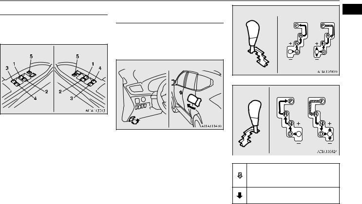
1 Selector lever positions
“P” PARK
This position locks the transmission to prevent the vehicle from moving. The engine can be started in this position.
“R” REVERSE
This position is to back up.
“N” NEUTRAL
At this position the transmission is disengaged.
“D” DRIVE
This position is for normal driving.
Refer to “5-Speed automatic transmission with sports mode” on page 6-32.
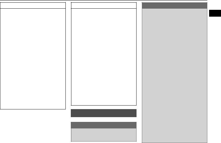
8-Speed automatic transmission with sports mode*
E08501001341
Selector lever operation
The transmission selects an optimum gear ratio automatically, depending on the speed of the vehicle and the position of the accelerator pedal.
The lock button must be pushed while the brake pedal is depressed to move the selector lever.
The lock button must be pushed to move the selector lever.
The lock button need not be pushed to move the selector lever.
 WARNING
If the lock button is always pushed to operate the selector lever, the lever may be accidentally shifted into the “P” (PARK) or “R” (REVERSE) position. Be sure not to push the lock button when performing
the operations indicated by  in the illustration.
Selector lever positions
“P” PARK
This position locks the transmission to prevent the vehicle from moving. The engine can be started in this position.
“R” REVERSE
This position is to back up.
“N” NEUTRAL
At this position the transmission is disengaged.
“D” DRIVE
This position is for normal driving.
1-15 Overview/Quick guide

Refer to “8-speed automatic transmission with sports mode” on page 6-39.
4-wheel drive operation*
Quick guide
1
E08502000048
|
|
|
Road conditions |
|
|
||
Driving mode |
Dry paved road |
Packed snow |
Gravel road |
Deep snow or |
Sandy road |
Rocky road |
|
|
and highway |
road |
muddy road |
||||
|
|
|
|
||||
Super select 4WD |
|
|
|
|
|
|
|
( P.6-46) |
2H or 4H |
4H |
4HLc or 4LLc |
4HLc or 4LLc |
4HLc or 4LLc |
4HLc or 4LLc |
|
Super select 4WD II |
|||||||
|
|
|
|
|
|
||
( P.6-50) |
|
|
|
|
|
|
|
|
|
|
|
|
|
|
|
Off Road mode-selector |
− |
− |
GRAVEL |
MUD/SNOW |
SAND |
ROCK |
|
( P.6-60) |
|||||||
|
|
|
|
|
|
||
|
|
|
|
|
|
|
|
Rear differential lock |
− |
− |
− |
Active* |
Active* |
Active* |
|
( P.6-61) |
|||||||
|
|
|
|
|
|
||
|
|
|
|
|
|
|
|
*:The OFF Road mode and the rear differential lock cannot be used at the same time. When the rear differential lock is set to ON, the OFF Road mode turns off. In addition, when the rear differential lock is ON, the OFF Road mode will be deactivated even if the OFF Road mode-selec- tor is operated.
 CAUTION
When driving on the off-road, confirm the conditions of the road surface and the landscape, and drive after confirming that the components of the suspension and the bottom of the front and rear bumper do not contact with the road surface. (Refer to “Vehicle dimensions” on page 11-4)
Overview/Quick guide |
1-16 |
Quick guide
|
|
|
4- Forward Collision Mitigation System |
|
|
|
|
1 |
|
Multi information display |
Type 2 |
|
|
|
|
|
(FCM) and Ultrasonic misacceleration |
|
|
|
|||
|
|
|
|
|
|
|
|
|
|
E08501201239 |
Mitigation System (UMS) OFF indica- |
|
|
|
|
|
Always stop the vehicle in a safe place before |
|
|
|
|
||
|
|
|
|
|
|||
|
tor display* P.6-102, 6-109 |
|
|
|
|
||
|
operating. |
5- Cruise control indicator display* |
|
|
|
|
|
|
The following information is included on the |
P.6-85 |
|
|
|
|
|
|
multi information display: odometer, tripme- |
|
|
|
|
||
|
6- Adaptive Cruise Control System |
|
|
|
|
||
|
ter, average fuel consumption etc. |
|
|
|
|
||
|
(ACC) display* P.6-90 |
|
|
|
|
||
|
|
|
|
|
|||
|
|
|
|
|
|||
Type 1 |
7- |
“ |
” or “ |
” mark indicator P.5-6 |
|
|
|
8- |
Information screen P.5-4 |
||
|
|
9- |
Selector lever position indicator dis- |
||
|
|
|
play (vehicles with 5A/T) P.6-34 |
||
|
|
|
(vehicles with 8A/T) P.6-41 |
||
|
|
10- |
Engine coolant temperature display |
||
|
|
|
P.5-7 |
|
|
|
|
11Odometer P.5-8 |
|||
|
|
12- |
Fuel remaining display P.5-7 |
||
|
|
13- |
Outside temperature display |
||
|
|
|
P.5-8 |
|
|
|
|
Refer “Multi information display” on page |
|||
|
|
5-3. |
|
|
|
1- Off Road mode indicator display* |
|
|
|
|
|
|
P.6-61 |
|
|
|
|
2- Drive mode indicator display* |
|
|
|
|
|
3- |
P.6-50 |
|
|
|
|
mark display P.5-6 |
|
|
|
|
|
|
|
|
|
|
|
1- Engine coolant temperature displayP.5-22
2- Selector lever position display*
P.6-34
3- Fuel remaining display P.5-22 4- Frozen road warning* P.5-21 5- Information display P.5-19 6- Service reminder P.5-23
Refer “Multi information display” on page 5-18.
1-17 Overview/Quick guide

General information
2
Fuel selection ................................................................................... |
2-2 |
Filling the fuel tank .......................................................................... |
2-3 |
Installation of accessories ................................................................ |
2-5 |
Modification/alterations to the electrical or fuel systems ................ |
2-5 |
Genuine parts ................................................................................... |
2-6 |
Used engine oils safety instructions ................................................ |
2-6 |
Fuel selection
Fuel selection
2 |
E00200104839 |
|
Petrol-powered vehicles
Unleaded petrol octane number
|
95 RON or higher |
|
If the “PREMIUM FUEL |
|
ONLY” label is attached to the |
|
fuel tank filler door, fill it up with |
|
premium fuel. |
Rec- Diesel-powered vehicles |
|
ommen |
Cetane number 45 or higher |
ded |
Cetane number (EN590) |
fuel |
51 or higher*1*2 |
|
*1: If the “DIESEL EN590” label |
|
is attached to the fuel tank filler |
|
door, fill it up with EN590. |
|
*2: If the “DIESEL Euro IV-PH” |
|
label is attached to the fuel tank |
|
filler door, fill it up with Euro IV- |
|
PH. |
 CAUTION
For unleaded petrol-powered vehicles, the use of leaded fuel can result in serious damage to the engine and catalytic converter. Do not use the leaded fuel.
 CAUTION
Diesel-powered vehicles with the “DIESEL EN590” or the “DIESEL Euro IV-PH” label on the fuel tank filler door are designed to use only diesel fuel that meets the EN590 or Euro IV-PH standard.
Use of any other type of diesel fuel would adversely affect the engine’s performance and durability.
For diesel-powered vehicles, if proper “winter” fuel is not used in winter, the diesel preheat indicator lamp may blink and the engine speed may not rise above the idling speed because of fuel freezing. In this case, keep the engine idling for approximately ten minutes, then turn off the ignition switch or put the operation mode in OFF and immediately turn it on or put in ON again to confirm that the diesel preheat indicator lamp is off. (Refer to “Diesel preheat indicator lamp” on page 5-51)
Ethanol/Gasohol (Petrol-pow- ered vehicles only)
A mixture of up to 10 % ethanol (grain alcohol) and 90 % unleaded petrol may be used in your vehicle, provided the octane number is at least as high as that recommended for unleaded petrol.
 CAUTION
Do not use more than 10 % concentration of ethanol (grain alcohol) by volume.
Use of more than 10 % concentration may lead to damage to your vehicle fuel system, engine, engine sensors and exhaust system.
Do not operate your vehicle on petrol containing methanol. Using this type of alcohol could adversely affect the vehicle’s performance and damage critical parts of the vehicle’s fuel system.
 NOTE
NOTE
For diesel fuel, due to the separation of paraffin, the fluidity decreases considerably as the temperature falls.
Because of this fact there are two kinds of fuel: “summer” and “winter”.
This must be considered in winter use. Select either of the two kinds of fuel in accordance with ambient temperature.
Above -5 °C: “summer” diesel Below -5 °C: “winter” diesel
When travelling abroad, find out in advance about the fuels served in local service stations.
2-2 General information
Filling the fuel tank
 NOTE
NOTE
Petrol-powered vehicles have the knock control system so that you can use unleaded petrol 90 RON or higher as an emergent measure in case unleaded petrol 95 RON or higher is not available on journey, etc.
In such a case, you don’t need to adjust the engine specially.
In case of using unleaded petrol 90 RON or higher, the engine performance level is reduced.
In petrol-powered vehicles, repeatedly driving short distance at low speeds can cause deposits to form in the fuel system and engine, resulting in poor starting and poor acceleration. If these problems occur, you are advised to add a detergent additive to the petrol when you refuel the vehicle. The additive will remove the deposits, thereby returning the engine to a normal condition. Be sure to use a MITSUBISHI MOTORS GENUINE FUEL SYSTEM CLEANER. Using an unsuitable additive could make the engine malfunction. For details, please contact the nearest authorised MITSUBISHI MOTORS dealer.
 NOTE
NOTE
Poor quality petrol can cause problems such as hard starting, stalling, engine noise and hesitation. If your experience these problems, try another brand and/or grade of petrol.
If the check engine warning lamp flashes, have the system checked as soon as possible at an authorised MITSUBISHI MOTORS dealer.
In diesel-powered vehicles, poor-quality diesel fuel can cause deposits form in the injector, resulting in black smoke and rough idling.
If these problems occur, you are advised to add a cleaning additive to the diesel fuel when you refuel the vehicle. The additive will break up and remove the deposits, thereby returning the engine to a normal condition. Be sure to use a MITSUBISHI MOTORS GENUINE DIESEL FUEL SYSTEM CLEANER. Using an unsuitable additive could make the engine malfunction. For detailed, please contact the nearest authorised MITSUBISHI MOTORS dealer.
Filling the fuel tank
E00200204175
 WARNING
When handling fuel, comply with the safety regulations displayed by garages and filling stations.
 WARNING
Fuel is highly flammable and explosive. 2 You could be burned or seriously injured
when handling it. When refueling your vehicle, always turn the engine off and keep away from flames, sparks, and smoking materials. Always handle fuel in wellventilated outdoor areas.
Before removing the fuel cap, be sure to get rid of your body’s static electricity by touching a metal part of the vehicle or fuel pump. Any static electricity on your body could create a spark that ignites fuel vapor.
Perform the whole refueling process (opening the fuel tank filler door, removing the fuel cap, etc.) by yourself. Do not let any other person come near the fuel tank filler. If you allowed a person to help you and that person was carrying static electricity, fuel vapor could be ignited.
Do not move away from the fuel tank filler until refueling is finished. If you moved away and did something else (for example, sitting on a seat) part-way through the refueling process, you could pick up a fresh charge of static electricity.
Be careful not to inhale fuel vapor. Fuel contains toxic substances.
Keep the doors and windows closed while refueling the vehicle. If they were open, fuel vapor could get into the cabin.
If the fuel cap must be replaced, use only a MITSUBISHI MOTORS genuine part.
General information |
2-3 |
Filling the fuel tank
Fuel tank capacity
2 Petrol-powered vehicles:70 litres Diesel-powered vehicles:68 litres
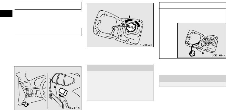
Refueling
1.Before filling with fuel, stop the engine.
2.The fuel tank filler is located on the rear left side of your vehicle.
Open the fuel tank filler door with the release lever located below the instrument panel.
3.Open the fuel tank filler tube by slowly turning the fuel cap anticlockwise.
1- Remove
2- Close
 CAUTION
Since the fuel system may be under pressure, remove the fuel cap slowly. This relieves any pressure or vacuum that might have built up in the fuel tank. If you hear a hissing sound, wait until it stops before removing the fuel cap. Otherwise, fuel may spray out, injuring you or others.
 NOTE
NOTE
While filling with fuel, hang the fuel cap on the hook (A) located on the inside of the fuel tank filler door.
4.Insert the gun in the tank port as far as it goes.
 CAUTION
Do not tilt the gun.
5.When the gun stops automatically, do not fill with fuel any more.
6.To close, turn the fuel cap slowly clockwise until you hear clicking sounds, then gently push the fuel tank filler door closed.
2-4 General information

|
|
|
|
|
|
|
Installation of accessories |
|
||||||
|
|
|
Improper installation of electrical parts |
Even when such parts are officially author- |
||||||||||
Installation of accessories |
||||||||||||||
|
could cause fire, please refer to the Modi- |
ised, for example by a “general operators per- |
||||||||||||
|
E00200302299 |
|
fication/alteration to the electrical or fuel |
mit” (an appraisal for the part) or through the |
2 |
|||||||||
|
|
|
|
|
|
|
|
|
|
|
|
|
||
Before fitting any accessories, please consult |
|
systems section within this owner’s man- |
execution of the part in an officially approved |
|
||||||||||
|
||||||||||||||
your authorised MITSUBISHI |
MOTORS |
|
ual. |
manner of construction, or when a single |
||||||||||
dealer. |
|
|
Using a cellular phone or radio set inside |
operation permit following the attachment or |
||||||||||
|
|
|
the vehicle without an external antenna |
installation of such parts, it cannot be |
||||||||||
CAUTION |
|
|
may cause electrical system interference, |
deduced from that alone, that the driving |
||||||||||
|
|
|
which could lead to unsafe vehicle opera- |
safety of your vehicles has not been affected. |
||||||||||
Your vehicle is equipped with |
a diagnosis |
|||||||||||||
|
tion. |
|
|
|
|
|
|
|
|
|
||||
connector for checking and servicing the |
|
Consider also that there basically exists no |
||||||||||||
|
Tyres and wheels which do not meet spec- |
|||||||||||||
electronic control system. |
|
|
||||||||||||
Do not connect a device other than a diagno- |
|
ifications must not be used. |
liability on the part of the appraiser or the |
|||||||||||
sis tool for inspections and service to this |
|
Refer to the “Specifications” section for |
official. Maximum safety can only be ensured |
|||||||||||
connector. Otherwise, the battery could be |
|
information regarding wheel and tyre |
with parts recommended, sold and fitted or |
|||||||||||
discharged, the electronic devices of the |
|
sizes. |
installed by an authorised MITSUBISHI |
|||||||||||
vehicle could malfunction, or other unex- |
|
Do not fail to read the accessories manu- |
MOTORS dealer (MITSUBISHI MOTORS |
|||||||||||
pected problems could result. |
|
|
als prior to the installation of accessories, |
GENUINE |
replacement |
parts |
and |
|||||||
In addition, malfunctions caused by connect- |
|
parts or other modifications to the vehi- |
MITSUBISHI MOTORS |
accessories). |
The |
|||||||||
ing a device other than a diagnosis tool may |
|
|||||||||||||
|
cle! |
same also |
pertains to |
modifications |
of |
|||||||||
not be covered under warranty. |
|
|
||||||||||||
|
|
|
|
MITSUBISHI vehicles with respect to the |
||||||||||
The installation of accessories, optional |
|
Important points! |
|
production specifications. For safety reasons, |
||||||||||
|
|
|||||||||||||
|
|
do not attempt any modifications other than |
||||||||||||
parts, etc., should only be carried out |
|
|
|
those that follow the recommendations of an |
||||||||||
within the limits prescribed by law in your |
Due to a large number of accessories and |
authorised MITSUBISHI MOTORS dealer. |
||||||||||||
country, and in accordance with the guide- |
replacement parts of different manufactures |
|
|
|
|
|
|
|
|
|
||||
lines and warnings contained within the |
available in the market, it is not possible, not |
|
|
|
|
|
|
|
|
|
||||
|
Modification/alterations to |
|
|
|
||||||||||
documents accompanying this vehicle. |
only for MITSUBISHI MOTORS but also an |
|
|
|||||||||||
Only MITSUBISHI MOTORS approved |
authorised MITSUBISHI MOTORS dealer, |
|
the electrical or fuel systems |
|
||||||||||
accessories should be fitted to your vehi- |
to check whether the attachment or installa- |
|
|
|
|
|
|
|||||||
|
|
|
|
E00200401495 |
||||||||||
cle. |
|
tion of such parts affects the overall safety of |
MITSUBISHI MOTORS has always manu- |
|||||||||||
|
|
your MITSUBISHI-vehicle. |
||||||||||||
|
|
factured safe, high quality vehicles. In order |
||||||||||||
to maintain this safety and quality, it is impor-
General information |
2-5 |
Genuine parts
|
|
tant that any accessory that is to be fitted, or |
Failure to use Genuine Parts may invalidate |
|
|
|
|
WARNING |
|||
|
|
any modifications carried out which involve |
any future warranty claim. MITSUBISHI |
||
|
|
Keep used engine oils out of reach of chil- |
|||
2 |
|
the electrical or fuel systems, should be car- |
MOTORS will not be liable for any malfunc- |
||
|
dren. |
||||
|
|
ried out in accordance with MITSUBISHI |
tion of your vehicle that may have been |
|
|
|
|
MOTORS guidelines. |
caused by the use of substitute parts in place |
|
|
|
|
|
of |
MITSUBISHI MOTORS GENUINE |
|
|
|
CAUTION |
PARTS. |
|
|
|
|
|
At the MITSUBISHI MOTORS dealer you |
|
|
|
|
Please consult an authorised MITSUBISHI |
|
||
|
|
can |
also get appropriate advice and the |
|
|
|
|
MOTORS dealer concerning any such fit- |
|
||
|
|
assembling of Genuine Parts will be handled |
|
||
|
|
ment or modification. |
|
||
|
|
If the wires interfere with the vehicle body or |
professionally. |
|
|
|
|
improper installation methods are used (pro- |
MITSUBISHI MOTORS GENUINE PARTS |
|
|
|
|
tective fuses not included, etc.), electronic |
are identified by this mark, and are available |
|
|
|
|
devices may be adversely affected, resulting |
at all authorised MITSUBISHI MOTORS |
|
|
|
|
in a fire or other accident. |
dealers. |
|
|
Genuine parts
E00200501685
Don’t play around with substitutes. MITSUBISHI MOTORS has gone to great lengths to bring you a superbly crafted vehicle offering the highest quality and dependability. Don’t reduce that quality and dependability by using substitute parts. Always use MITSUBISHI MOTORS GENUINE PARTS designed and manufactured to maintain your MITSUBISHI vehicle at top performance. The operation of vehicle components can be less efficient in case of using Non-Genuine Parts.
Used engine oils safety instructions
E00200601279
 WARNING
Prolonged and repeated contact may cause serious skin disorders, including dermatitis and cancer.
Avoid contact with the skin as far as possible and wash thoroughly after any contact.
2-6 General information

Locking and unlocking
3
Keys ................................................................................................. |
3-2 |
Key number tag ................................................................................ |
3-2 |
Electronic immobilizer (Anti-theft starting system) ........................ |
3-3 |
Keyless entry system ....................................................................... |
3-4 |
Keyless operation system* ............................................................... |
3-7 |
Doors .............................................................................................. |
3-15 |
Central door locks .......................................................................... |
3-16 |
“Child-protection” rear doors ........................................................ |
3-17 |
Tailgate .......................................................................................... |
3-18 |
Security alarm system*................................................................... |
3-20 |
Electric window control ................................................................. |
3-24 |
Sunroof* ......................................................................................... |
3-26 |
Keys
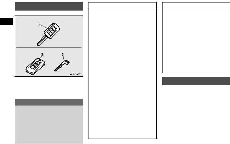
Keys
E00300103992
3 |
Keyless entry key |
|
Keyless operation key
1- Keyless entry key
2- Keyless operation key
3- Emergency key
 WARNING
When carrying a key on flights, do not press any switches on the key while on the plane. If a switch is pressed on the plane, the key emits electromagnetic waves, which could adversely affect the plane’s flight operation.
When carrying a key in a bag, be careful that no switches on the key can be easily pressed by mistake.
 NOTE
NOTE
The key is a precision electronic part with a built-in signal transmitter. Please observe the following in order to prevent a malfunction.
•Do not leave anywhere that is exposed to direct sunlight, for example on the dashboard.
•Do not disassemble or modify.
•Do not excessively bend the key or subject it to a strong impact.
•Do not expose to water.
•Keep away from magnetic key rings.
•Keep away from audio systems, personal computers, TVs, and any other equipment that generates a magnetic field.
•Keep away from devices that emit strong electromagnetic waves, such as cellular phones, wireless devices and high frequency equipment (including medical devices).
•Do not wash with ultrasonic cleaners or similar equipment.
•Do not leave the key where it may be exposed to high temperature or high humidity.
The engine is designed so that it will not start if the ID code registered in the immobilizer computer and the key’s ID code do not match. Refer to the section entitled “Electronic immobilizer” for details and key usage.
 NOTE
NOTE
[For vehicles equipped with the security alarm system]
Pay attention to the following if the security alarm is set to “Active”. Refer to “Security alarm system” on page 3-20.
•If the security alarm is in the system armed mode, the alarm will sound if the doors are opened after being unlocked with the key, the inside lock knob or the central door lock switch.
•Even if the security alarm is set to “Active”, the system preparation mode is not entered if the keyless entry system or the keyless operation function was not used to lock the vehicle.
Key number tag
E00312701063
The key number is stamped on the tag as indicated in the illustration.
Make a record of the key number and store the key and key number tag in separate places, so that you can order a key from your authorised MITSUBISHI MOTORS dealer in the event the original keys are lost.
3-2 Locking and unlocking
Electronic immobilizer (Anti-theft starting system)
|
|
|
|
|
NOTE |
|
|
|
|
|
NOTE |
|
|||
|
|
|
|
|
|
|
|||||||||
|
|
|
|
|
|
|
|
|
|
|
|
|
|
|
|
|
|
|
|
|
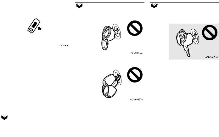
• When the key contacts a key ring or other |
|
|
|
|
|
• When the key contacts or is close to other |
|
|||
|
|
|
|
|
metallic or magnetic object |
|
|
|
|
|
immobilizing keys (including keys of other |
|
|||
|
|
|
|
|
|
|
|
|
|
|
|
vehicles) |
|
||
|
|
|
|
|
|
|
3 |
||||||||
|
|
|
|
|
|
|
|||||||||
|
|
|
|
|
|
|
|
|
|
|
|
|
|
|
|
|
|
|
|
|
|
|
|
|
|
|
|
|
|
|
|
|
|
|
|
|
|
|
|
|
|
|
|
|
|
|
|
|
|
|
|
|
|
|
|
|
|
|
|
|
|
|
|
|
|
|
|
• When the key grip contacts metal of |
|
|
|
|
||||
Electronic immobilizer |
|
another key |
|
|
|
|||||||
(Anti-theft starting system) |
|
|
|
|
In cases like these, remove the object or |
|||||||
|
|
|
|
|||||||||
|
|
E00300203401 |
|
|
|
|
additional key from the vehicle key. Then |
|||||
The electronic immobilizer is designed to |
|
|
|
|
try again to start the engine. If the engine |
|||||||
|
|
|
|
does not start, |
contact |
an |
authorised |
|||||
reduce significantly the possibility of vehicle |
|
|
|
|
||||||||
|
|
|
|
MITSUBISHI MOTORS dealer. |
|
|||||||
theft. The purpose of the system is to immo- |
|
|
|
|
|
|||||||
|
|
|
|
If you lose one of them, contact an author- |
||||||||
bilize the vehicle if an invalid start is |
|
|
|
|
||||||||
|
|
|
|
ised MITSUBISHI MOTORS dealer as soon |
||||||||
attempted. A valid start attempt can only be |
|
|
|
|
||||||||
|
|
|
|
as possible. To obtain a replacement or extra |
||||||||
achieved, using a key “registered” to the |
|
|
|
|
||||||||
|
|
|
|
spare key, take your vehicle and all remain- |
||||||||
|
|
|
||||||||||
immobilizer system. |
|
|
|
|
ing keys to an authorised MITSUBISHI |
|||||||
|
|
|
|
|
|
|
MOTORS dealer. All the keys have to be re- |
|||||
|
|
NOTE |
|
|
|
|
registered in the immobiliser computer unit. |
|||||
|
|
|
|
|
|
The immobilizer can register as follows. |
||||||
|
|
|
|
|
|
|
||||||
[Vehicles without keyless operation system] |
||||||||||||
|
|
|
|
• Keyless entry key: up to 8 different keys |
||||||||
|
|
In the following cases, the vehicle may not |
|
|
|
|
||||||
|
|
|
|
|
|
• Keyless operation |
key: up |
to |
4 different |
|||
|
|
be able to receive the registered ID code |
|
|
|
|
||||||
|
|
|
|
|
|
keys |
|
|
|
|||
|
|
from the registered key and engine may not |
|
|
|
|
|
|
|
|||
|
|
|
|
|
|
|
|
|
|
|
||
|
|
start. |
|
|
|
|
|
|
|
|
|
|
|
|
|
|
|
|
|
|
|
|
|
|
|
Locking and unlocking |
3-3 |
 Loading...