


00-1
GENERAL
CONTENTS
HOW TO USE THIS MANUAL . . . . . . . . . . . . . . |
2 |
Models . . . . . . . . . . . . . . . . . . . . . . . . . . . . . . . . . . . . . . . |
2 |
|
Model Indications . . . . . . . . . . . . . . . . . . . . . . . . . . . . . |
2 |
Model code . . . . . . . . . . . . . . . . . . . . . . . . . . . . . . . . . . |
3 |
|
VEHICLE IDENTIFICATION . . . . . . . . . . . . . . . . . . |
2 |
MAJOR SPECIFICATIONS . . . . . . . . . . . . . . . . . . |
4 |
|
|
|
|
|
|
|
|
|
|
|

00-2 GENERAL – How To Use This Manual/Vehicle Identification
HOW TO USE THIS MANUAL
MODEL INDICATIONS
The following abbreviations are used in this manual for identification of model types. MPI: Indicates the multi point fuel injection.
GD-D: Indicates the direct injection diesel. GDI: Indicates the gasoline direct injection.
M/T: Indicates the manual transmission, or models equipped with the manual transmission. A/T: Indicates the automatic transmission, or models equipped with the automatic transmission. A/C: Indicates the air conditioner.
VEHICLE IDENTIFICATION
MODELS
Model code |
|
Engine model |
Transmission model |
Fuel supply system |
|
|
|
|
|
|
|
DG1A |
LNDEL6/R6 |
4G13 MPI (1,299 mL) |
F5MR1 <5M/T> |
MPI |
|
|
|
|
|
(Multi Point Fuel Injection) |
|
|
LNJEL6/R6 |
|
|
|
|
|
|
|
|
|
|
|
|
|
|
|
|
|
LNPEL6/R6 |
|
|
|
|
|
|
|
|
|
|
DG4A |
LNDFL6/R6 |
F9Q1 (1,870 mL) |
F5MV1 <5M/T> |
DI-D |
|
|
|
|
|
(Direct Injection Diesel) |
|
|
LNJFL6/R6 |
|
|
|
|
|
|
|
|
|
|
|
|
|
|
|
|
|
LNPFL6/R6 |
|
|
|
|
|
|
|
|
|
|
DG5A |
LNDCL6 |
4G93 GDI (1,834 mL) |
F5M42 <5M/T> |
GDI |
|
|
|
|
|
(Gasoline Direct Injection) |
|
|
LNJCL6/R6 |
|
|
||
|
|
|
|
|
|
|
|
|
|
|
|
|
LRJCL6/R6 |
|
F4A42 |
|
|
|
|
|
<INVECS-II 4A/T with |
|
|
|
|
|
Sports Mode> |
|
|
|
|
|
|
|
|
|
LNPCL6/R6 |
|
F5M42 <5M/T> |
|
|
|
|
|
|
|
|
|
LRPCL6/R6 |
|
F4A42 |
|
|
|
|
|
<INVECS-II 4A/T with |
|
|
|
|
|
Sports Mode> |
|
|
|
|
|
|
|
|

GENERAL – Vehicle Identification |
00-3 |
||||
|
|
MODEL CODE |
|
|
|
|
|
|
|
||
|
|
|
|
|
|
|
|
No. |
Items |
Contents |
|
|
|
|
|
|
|
|
|
1 |
Development |
DG: |
MITSUBISHI SPACE STAR |
|
|
|
|
|
|
|
|
2 |
Engine type |
1: |
1,299 mL petrol engine |
|
|
|
|
4: |
1,870 mL diesel engine |
|
|
|
|
5: |
1,834 mL petrol engine |
|
|
|
|
|
|
|
|
3 |
Sort |
A: |
Passenger car |
|
|
|
|
|
|
|
|
4 |
Body style |
L: |
5-door |
|
|
||||
|
|
|
|
|
|
|
|
5 |
Transmission type |
N: |
5-speed manual |
|
|
|
|
|
transmission |
|
|
|
|
R: |
4-speed automatic |
|
|
|
|
|
transmission |
|
|
|
|
|
|
|
|
6 |
Trim level |
D: |
Family |
|
|
|
|
J: |
Comfort |
|
|
|
|
P: |
Sport |
|
|
|
|
||
|
|
|
|
|
|
|
|
7 |
Specification engine |
E: |
MPI |
|
|
|
feature |
F: |
DI-D |
|
|
|
|
C: |
GDI |
|
|
|
|
|
|
|
|
8 |
Steering wheel |
L: |
Left hand |
|
|
|
location |
R: |
Right hand |
|
|
|
|
|
|
|
|
9 |
Destination |
6: |
For Europe |
|
|
|
|
|
|

00-4 |
GENERAL – Major Specifications |
MAJOR SPECIFICATIONS
|
|
|
|
|
|
|
3 |
3*1 |
|
|
|
9 |
|
|
|
|
|
|
|
|
|
|
|
5 |
|
|
7 |
|
4 |
|
8 |
|
|
6 |
|
2 |
|
|
|
|
1 |
|
|
|
|
|
|
|
|
|
|
|
|
|
|
|
|
|
|
Items |
|
|
DG1A |
|
|
DG4A |
|
|
|
|
|
|
|
|
|
LNDEL6 |
LNJEL6 |
LNPEL6 |
LNDFL6 |
LNJFL6 |
|
LNPFL6 |
|
|
|
|
|
/R6 |
/R6 |
/R6 |
/R6 |
|
/R6 |
|
/R6 |
Vehicle |
|
Overall length |
1 |
4,030 |
|
|
|
|
|
|
|
dimensions |
|
|
|
|
|
|
|
|
|
|
|
|
Overall width |
2 |
1,715 |
|
|
|
|
|
|
|
|
mm |
|
|
|
|
|
|
|
|
|
|
|
|
Overall height |
3 |
1,515, |
|
|
|
|
|
|
|
|
|
|
|
|
|
|
|
|
|
|||
|
|
(unladen) |
|
1,555*1 |
|
|
|
|
|
|
|
|
|
Wheelbase |
4 |
2,500 |
|
|
|
|
|
|
|
|
|
|
|
|
|
|
|
|
|
|
|
|
|
Track-front |
5 |
1,475 |
|
|
|
|
|
|
|
|
|
|
|
|
|
|
|
|
|
|
|
|
|
Track-rear |
6 |
1,470 |
|
|
|
|
|
|
|
|
|
|
|
|
|
|
|
|
|
|
|
|
|
Overhang-front |
7 |
835 |
|
|
|
|
|
|
|
|
|
|
|
|
|
|
|
|
|
|
|
|
|
Overhang-rear |
8 |
695 |
|
|
|
|
|
|
|
|
|
|
|
|
|
|
|
|
|
|
|
|
|
Ground clear- |
9 |
155 |
|
|
|
|
|
|
|
|
|
ance (unladen) |
|
|
|
|
|
|
|
|
|
|
|
|
|
|
|
|
|
|
|
|
|
Vehicle |
|
Kerb weight |
|
1,158 |
1,170 |
1,173 |
1,248 |
|
1,260 |
|
1,258 |
weight kg |
|
|
|
|
|
|
|
|
|
|
|
|
Max. gross vehicle |
1,655 |
|
|
1,730 |
|
|
|
|
||
|
|
weight |
|
|
|
|
|
|
|
|
|
|
|
|
|
|
|
|
|
|
|
|
|
|
|
Max. axle weight |
|
855 |
|
|
920 |
|
|
|
|
|
|
rating-front |
|
|
|
|
|
|
|
|
|
|
|
|
|
|
|
|
|
|
|
|
|
|
|
Max. axle weight |
|
830 |
|
|
850 |
|
|
|
|
|
|
rating-rear |
|
|
|
|
|
|
|
|
|
|
|
|
|
|
|
|
|
|
|
|
|
Seating capacity |
|
|
5 |
|
|
|
|
|
|
|
|
|
|
|
|
|
|
|
|
|
|
|
|
Engine |
|
Model No. |
|
4G13 |
|
|
F9Q1 |
|
|
|
|
|
|
|
|
|
|
|
|
|
|
|
|
|
|
Total displacement |
1,299 |
|
|
1,870 |
|
|
|
|
|
|
|
mL |
|
|
|
|
|
|
|
|
|
Transmission |
|
Model No. |
|
F5MR1 |
|
|
F5MV1 |
|
|
|
|
|
|
|
|
|
|
|
|
|
|
|
|
|
|
Type |
|
5 speed-manual |
|
|
|
|
|
|
|
|
|
|
|
|
|
|
|
||||
Fuel system |
|
Fuel supply system |
Multi Point Fuel Injection |
|
Direct Injection Diesel |
|
|
||||
|
|
|
|
|
|
|
|
|
|
|
|
NOTE:
*1: Vehicles with roof rails

|
|
GENERAL – Major Specifications |
|
00-5 |
||||
|
|
|
|
|
|
|
|
|
Items |
|
|
|
DG5A |
|
|
|
|
|
|
|
|
LNDCL6 |
LNJCL6/R6 |
LNPCL6/R6 |
LRJCL6/R6 |
LRPCL6/R6 |
|
|
|
|
|
|
|
|
|
Vehicle |
Overall length |
|
1 |
4,030 |
|
|
|
|
dimensions |
|
|
|
|
|
|
|
|
Overall width |
|
2 |
1,715 |
|
|
|
|
|
mm |
|
|
|
|
|
|
|
|
Overall height |
|
3 |
1,515, |
|
|
|
|
|
|
|
|
|
|
|
|||
|
(unladen) |
|
|
1,555*1 |
|
|
|
|
|
Wheelbase |
|
4 |
2,500 |
|
|
|
|
|
|
|
|
|
|
|
|
|
|
Track-front |
|
5 |
1,475 |
|
|
|
|
|
|
|
|
|
|
|
|
|
|
Track-rear |
|
6 |
1,470 |
|
|
|
|
|
|
|
|
|
|
|
|
|
|
Overhang-front |
|
7 |
835 |
|
|
|
|
|
|
|
|
|
|
|
|
|
|
Overhang-rear |
|
8 |
695 |
|
|
|
|
|
|
|
|
|
|
|
|
|
|
Ground clear- |
|
9 |
150 |
|
|
|
|
|
ance (unladen) |
|
|
|
|
|
|
|
|
|
|
|
|
|
|
|
|
Vehicle |
Kerb weight |
|
|
1,228 |
1,240 |
1,238 |
1,255 |
1,253 |
weight kg |
|
|
|
|
|
|
|
|
Max. gross vehicle |
|
1,730 |
|
|
|
|
||
|
weight |
|
|
|
|
|
|
|
|
|
|
|
|
|
|
|
|
|
Max. axle weight |
|
920 |
|
|
|
|
|
|
rating-front |
|
|
|
|
|
|
|
|
|
|
|
|
|
|
|
|
|
Max. axle weight |
|
850 |
|
|
|
|
|
|
rating-rear |
|
|
|
|
|
|
|
|
|
|
|
|
|
|
|
|
Seating capacity |
|
|
|
5 |
|
|
|
|
|
|
|
|
|
|
|
|
|
Engine |
Model No. |
|
4G93 |
|
|
|
|
|
|
|
|
|
|
|
|
|
|
|
Total displacement |
|
1,834 |
|
|
|
|
|
|
mL |
|
|
|
|
|
|
|
|
|
|
|
|
|
|
|
|
Transmission |
Model No. |
|
F5M42 |
|
|
F4A42 |
|
|
|
|
|
|
|
|
|||
|
Type |
|
5 speed-manual |
|
INVECS-II 4A/T with Sports |
|||
|
|
|
|
|
|
|
Mode |
|
Fuel system |
Fuel supply system |
|
Gasoline Direct Injection |
|
|
|
||
|
|
|
|
|
|
|
|
|
NOTE:
*1: Vehicles with roof rails

NOTES

11A-1
ENGINE
CONTENTS
ENGINE <4G9> . . . . . . . . . . . . . . . . . . . . . . . . . . . . . . . . . . . . . . . . . . . . . . . . . . . . . . |
11A |
ENGINE <4G1> . . . . . . . . . . . . . . . . . . . . . . . . . . . . . . . . . . . . . . . . . . . . . . . . . . . . . . |
11B |
ENGINE <F9Q1> . . . . . . . . . . . . . . . . . . . . . . . . . . . . . . . . . . . . . . . . . . . . . . . . . . . . . |
11C |
|
|
|
|

11A-2
ENGINE <4G9>
CONTENTS
GENERAL . . . . . . . . . . . . . . . . . . . . . . . . . . . . . . . . . |
3 |
CAMSHAFT AND CAMSHAFT OIL SEAL . . . . |
5 |
Outline of Changes . . . . . . . . . . . . . . . . . . . . . . . . . . . 3
CRANKSHAFT REAR OIL SEAL <A/T> . . . . 10
SERVICE SPECIFICATIONS . . . . . . . . . . . . . . . . . 3
CYLINDER HEAD GASKET . . . . . . . . . . . . . . . . 12
SEALANTS . . . . . . . . . . . . . . . . . . . . . . . . . . . . . . . . 3
ENGINE ASSEMBLY . . . . . . . . . . . . . . . . . . . . . . 15
SPECIAL TOOLS . . . . . . . . . . . . . . . . . . . . . . . . . . . 3

ENGINE <4G9> – General/Service Specifications/Sealants/Special Tools |
11A-3 |
GENERAL
OUTLINE OF CHANGES
Since the resin intake manifold is adopted, the fuel system is changed, and the vehicle with A/T is added to the lineup, the following service adjustment procedures are made.
Other service procedures are the same as before.
SERVICE SPECIFICATIONS
Items |
|
Standard value |
Limit |
|
|
|
|
Idle speed r/min |
A/T |
650 ± 100 |
– |
|
|
|
|
Cylinder head bolt shank length mm |
|
– |
96.4 |
|
|
|
|
SEALANTS
Items |
Specified sealants |
Remarks |
|
|
|
Beam camshaft cap and cylinder |
3M ATD Part No.8660 or equivalent |
Semi-drying sealant |
head |
|
|
|
|
|
Camshaft position sensor support |
MITSUBISHI GENUINE PART |
|
|
MD970389 or equivalent |
|
|
|
|
Drive plate bolt |
3M Stud locking 4170 or equivalent |
– |
|
|
|
SPECIAL TOOLS
Tool |
Number |
Name |
Use |
|
|
|
|
|
MB990767 |
End yoke holder |
Holding the camshaft sprocket |
|
|
|
|
|
MD998719 |
Crankshaft pulley |
Holding the camshaft sprocket |
|
|
holder pin |
|
|
|
|
|
|
MD998762 |
Circular packing |
Press-fitting the circular packing |
|
|
installer |
|
|
|
|
|
|
MD998713 |
Camshaft oil seal |
Press-fitting the camshaft oil seal |
|
|
installer |
|
|
|
|
|

11A-4 |
ENGINE <4G9> – Special Tools |
||
|
|
|
|
Tool |
Number |
Name |
Use |
|
|
|
|
|
MD998781 |
Flywheel stopper |
Securing the drive plate |
|
|
|
|
|
MD998776 |
Crankshaft rear oil |
Press-fitting the crankshaft rear oil seal |
|
|
seal installer |
|
|
|
|
|
|
MB990938 |
Handle |
|
|
|
|
|
|
MB991653 |
Cylinder head bolt |
Cylinder head bolt removal and installation |
|
|
wrench |
|
|
|
|
|
|
GENERAL |
Engine lifter |
Supporting the engine assembly during |
|
SERVICE |
|
removal and installation of the transmission |
|
TOOL |
|
|
|
MZ203827 |
|
|
|
|
|
|
|
MB991453 |
Engine hanger |
|
|
|
assembly |
|
|
|
|
|
|
ENGINE <4G9> – Camshaft and Camshaft Oil Seal |
11A-5 |
||
CAMSHAFT AND CAMSHAFT OIL SEAL |
|
|
||
REMOVAL AND INSTALLATION |
|
|
|
|
|
|
|
|
|
|
Pre-removal and Post-installation Operation |
|
|
|
|
D Prevention of Fuel Discharge <before removal only> |
D Under Cover Removal and Installation |
|
|
|
D Fuel Leak Check <after installation only> |
D Engine Coolant Draining and Supplying |
|
|
|
D Air Bleeding the High Pressure Fuel Path |
D Air Cleaner Removal and Installation |
|
|
|
<after installation only> |
|
|
|
|
[Refer to GROUP 13A – Fuel Pump (High pressure).] |
|
|
|
|
|
|
|
|
|
3.0 Nm |
|
|
|
|
|
1 |
|
|
|
|
8 |
|
|
|
|
|
|
|
|
|
|
7.0 Nm |
|
|
|
|
|
|
|
|
|
|
7 |
|
|
|
|
|
|
|
|
|
5 |
6 |
9 |
15 |
|
|
|
|
||
|
|
|
|
|
|
|||||
|
|
|
|
|
|
|
|
|
||
|
3 |
|
|
|
|
|
5.0 Nm |
|
|
|
|
|
|
|
|
|
12 |
|
|
|
|
|
|
|
|
|
|
|
|
|
|
|
|
|
|
|
|
|
|
10 – 12 Nm |
|||
|
|
10 |
11 |
|
18 |
17 |
|
|
||
|
|
|
|
|
|
|||||
|
|
13 |
|
|
|
|
|
|||
|
|
|
|
|
|
|
|
|||
|
|
5.0 Nm |
14 |
|
3.4 Nm |
|||||
|
|
|
|
|
|
|
||||
|
2 |
4 |
19 |
|
|
|
|
|
|
|
|
|
|
|
|
|
|
|
|
||
|
|
|
|
|
|
|
|
21 |
|
|
|
|
16 |
|
|
20 |
|
|
22 |
|
|
|
|
|
|
|
|
|
|
|||
|
|
|
|
|
|
|
|
|
||
Removal steps |
|
|
|
|
|
|
|
|||
|
|
|
|
|
|
|
|
|||
"FA 1. |
Engine cover |
|
|
|
|
12. |
Camshaft position sensor connector |
|||
2. |
Crank angle sensor connector |
|
13. |
Engine coolant temperature sensor |
||||||
3. |
Fuel pressure sensor |
|
|
|
|
|
connector |
|||
4. |
Oxygen sensor (front) connector |
|
14. |
Engine coolant temperature gauge |
||||||
5. |
Control wiring harness and EGR |
|
|
unit connector |
||||||
|
wiring harness combination |
|
|
|
|
15. |
Control wiring harness |
|||
|
connector |
|
|
|
|
|
16. |
PCV hose |
||
6. |
Purge control solenoid valve |
|
|
|
|
17. |
Breather hose |
|||
|
connector |
|
|
|
|
|
D |
Ignition coil (Refer to GROUP 16. |
||
7. |
Throttle position sensor connector |
|
D |
Intake manifold (Refer to GROUP 15.) |
||||||
8. |
Throttle valve control servo |
|
|
|
|
D |
Timing belt |
|||
|
connector |
|
|
|
|
|
18. |
Connector bracket (injector wiring |
||
9. |
Control wiring harness and injector |
|
|
harness) |
||||||
|
wiring harness combination |
|
|
|
|
19. |
Rocker cover (intake side) |
|||
|
connector |
|
|
|
|
|
20. |
Rocker cover gasket |
||
10. |
Ignition coil connector |
|
|
|
|
21. |
Rocker cover (exhaust side) |
|||
11. |
Ignition failure sensor connector |
|
22. |
Rocker cover gasket |
||||||

11A-6 |
ENGINE <4G9> – Camshaft and Camshaft Oil Seal |
Apply engine oil to all
sliding parts during
21 – 25 Nm
installation .
10 – 12 Nm
29
25
10 – 12 Nm
31

 26
26
23
23
88 Nm
35 Nm |
24 |
|
21 – 25 Nm
30 


22 Nm
33
32
28 27
27
12 – 15 Nm
AA" "EA 23. |
Camshaft sprocket |
D |
Fuel pump (high pressure) assembly |
24. |
Idler pulley |
"BA 29. |
(Refer to GROUP 13A.) |
25. |
Timing belt rear upper cover |
Beam camshaft cap |
|
"DA 26. |
Camshaft oil seal |
30. |
Beam camshaft cap gasket |
27. |
Camshaft position sensor support |
"AA 31. |
Camshaft (intake side) |
"CA 28. |
Circular packing |
"AA 32. |
Camshaft (exhaust side) |
|
|
33. |
Camshaft position sensing cylinder |

ENGINE <4G9> – Camshaft and Camshaft Oil Seal |
11A-7 |
Lubrication points
|
<Seen from underneath |
φ3mm |
beam camshaft cap> |
Sealant: 3M ATD Part No.8660 or equivalent
Lip section
Sealant: |
Engine oil |
MITSUBISHI GENUINE PART |
|
|
|
MD970389 or equivalent |
|
<Seen from above cylinder head>
Sealant: 3M ATD Part No.8660 or equivalent
11A-8 |
ENGINE <4G9> – Camshaft and Camshaft Oil Seal |
MB990767
MD998719
Camshaft sprocket side
Screw hole
|
Exhaust camshaft |
|
|
|
|
Approx. |
Approx. |
106_ |
101_ |
|
Dowel pin |
|
||
Intake side |
|
|
Exhaust side |
|
|
|
|
|
|
|
|
|
|
|
28 |
|
27 |
31 |
32 |
20 |
19 |
23 |
24 |
|
12 11 |
3 |
15 |
16 |
|
8 |
7 |
1 |
5 |
6 |
Intake side |
|
|
|
Exhaust |
|
|
|
|
side |
14 13 |
2 |
9 |
10 |
|
22 21 |
4 |
17 |
18 |
|
30 |
29 |
25 |
26 |
|
Front of engine
REMOVAL SERVICE POINT
AA" CAMSHAFT SPROCKET REMOVAL
INSTALLATION SERVICE POINTS
"AA CAMSHAFT INSTALLATION
1.Apply engine oil to journals and cams of the camshafts.
2.Install the camshafts on the cylinder head.
Caution
Be careful not to confuse the intake camshaft with the exhaust one. There is a screw hole for the cam position sensing cylinder mounting bolt on the exhaust-side camshaft.
"BA BEAM CAMSHAFT CAP INSTALLATION
1. Place the camshaft dowel pin as shown in the illustration.
2.Tighten the beam camshaft cap mounting bolts to the specified torque in the order shown in the illustration.
Tightening torque: D : 10 – 12 Nm d : 21 – 25 Nm
ENGINE <4G9> – Camshaft and Camshaft Oil Seal |
11A-9 |
"CA CIRCULAR PACKING INSTALLATION
Use the special tool to press-fit the circular packing as shown in the illustration.
MD998762
Press-fitting depth 2 mm
|
|
|
"DA CAMSHAFT OIL SEAL INSTALLATION |
|
|
|
|
1. |
Apply engine oil to the entire circumference of the oil seal |
|
|
|
|
lip. |
|
|
|
2. |
Press-fit the oil seal as shown in the illustration. |
|
|
|
"EA CAMSHAFT SPROCKET INSTALLATION |
|
|
|
|
Use the special tool to secure the camshaft sprocket in the |
|
|
|
|
same way as during removal, and then tighten the bolt to |
|
|
MD998713 |
|
the specified torque. |
|
|
|
|
|
|
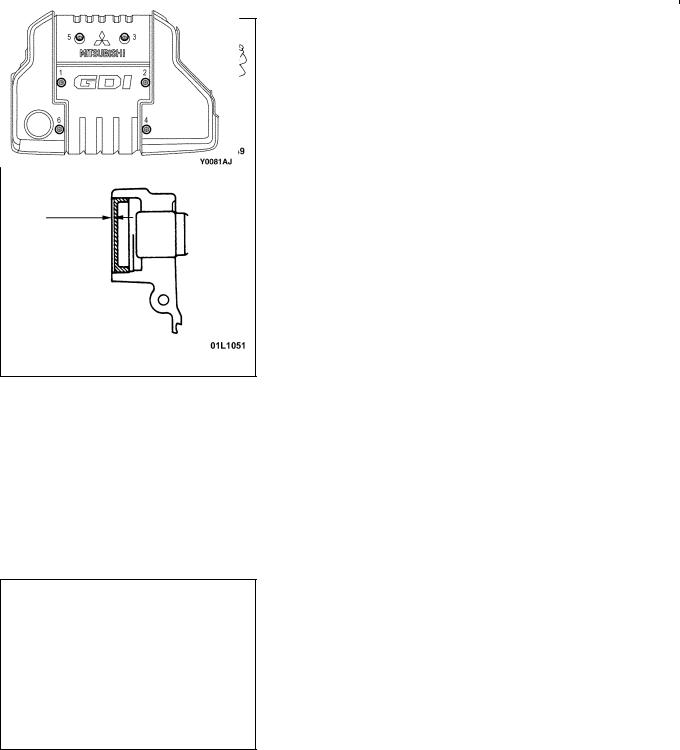
"FA ENGINE COVER INSTALLATION
1.Temporarily tighten the mounting bolt in the order of the numbers shown in the illustration so that the engine cover can move easily by hand.
2.Tighten the mounting bolt to the specified torque in the order of the numbers shown in the illustration.
Tightening torque: 3.0 Nm

11A-10 ENGINE <4G9> – Crankshaft Rear Oil Seal <A/T>
CRANKSHAFT REAR OIL SEAL <A/T>
REMOVAL AND INSTALLATION
Pre-removal and Post-installation Operation
DTransmission Assembly Removal and Installation (Refer to GROUP 23.)
3 |
1 |
93 – 103 Nm |
2
4 


Removal steps
AA" "BA 1. Drive plate bolts "BA 2. Adapter plate "BA 3. Drive plate
"AA 4. Crankshaft rear oil seal
REMOVAL SERVICE POINT
AA" DRIVE PLATE BOLTS REMOVAL
Use the special tool to secure the drive plate, and remove the bolts.
MD998781

|
ENGINE <4G9> – Crankshaft Rear Oil Seal <A/T> |
11A-11 |
||
|
|
INSTALLATION SERVICE POINTS |
|
|
Crankshaft |
|
|
||
|
"AA CRANKSHAFT REAR OIL SEAL INSTALLATION |
|||
rear oil seal |
Crankshaft |
|||
MD990938 |
1. Apply a small mount of engine oil to the entire |
|||
|
||||
|
|
circumference of the oil seal lip. |
|
|
2.Install the oil seal by tapping it as far as the chamfered position of the oil seal case as shown in the illustration.
|
"BA DRIVE PLATE/ADAPTOR PLATE/DRIVE PLATE |
|
MD998776 |
BOLTS INSTALLATION |
|
1. |
Clean off all sealant, oil and other substances which are |
|
|
|
adhering to the threaded bolts, crankshaft thread holes |
|
|
and the drive plate. |
2. |
Apply oil to the bearing surface of the drive plate bolts. |
|
3. |
Apply oil to the crankshaft thread holes. |
|
4. |
Apply sealant to the threaded mounting holes. |
|
|
|
Specified sealant: 3M Stud locking 4170 or equivalent |
5. |
Use the special tool to secure the drive plate, and then |
|
|
|
tighten the bolts to the specified torque. |
Specified torque: 93 – 103 Nm
11A-12 |
ENGINE <4G9> – Cylinder Head Gasket |
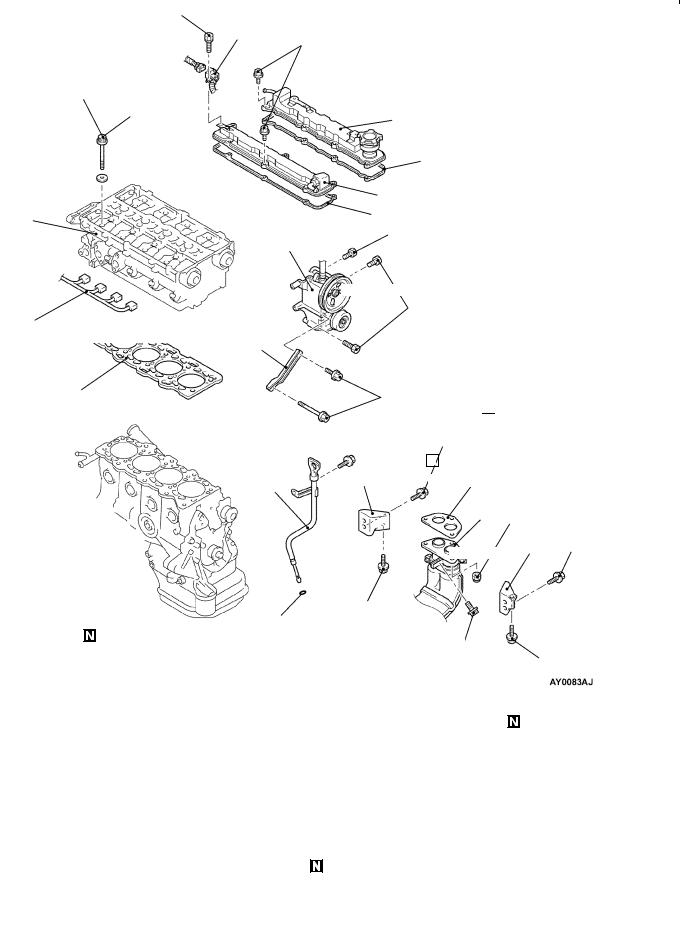
CYLINDER HEAD GASKET
REMOVAL AND INSTALLATION
Pre-removal and Post-installation Operation |
|
D Engine Cover Removal and Installation |
D Air Cleaner Removal and Installation |
(Refer to P.11A-5.) |
D Intake Manifold Removal and Installation |
D Prevention of Fuel Discharge <before removal only> |
(Refer to GROUP 15.) |
D Fuel Leak Check <after installation only> |
D Fuel Pump (high-pressure) Assembly Removal and |
D Air Bleeding the High Pressure Fuel Path<after |
Installation (Refer to GROUP 13A.) |
installation only> |
D Timing Belt Rear Upper Cover Removal and |
[Refer to GROUP 13A – Fuel Pump (High-pressure).] |
Installation (Refer to P.11A-5.) |
D Under Cover Removal and Installation |
D Thermostat Case Assembly and Radiator upper hose |
D Engine Coolant Draining and Supplying |
Removal and Installation |
D Engine Oil Draining and Supplying |
(Refer to GROUP 14 – Water Hose and Water Pipe.) |
|
|
10 – 12 Nm
7
3.4 Nm
74 Nm → 0 Nm → 20 Nm → +90_ → +90_
12
10
11 


8
13 |
9 |
|
|
22 Nm
5
44 Nm
1
4
14
49 Nm
35 Nm
3
6
2
34 Nm
3 |
35 Nm |
19 Nm
34 Nm
19 Nm
|
|
ENGINE <4G9> – Cylinder Head Gasket |
11A-13 |
||
|
Removal steps |
|
|
|
|
|
1. |
Injector harness connector |
8. |
Rocker cover (intake side) |
|
|
2. |
Front exhaust pipe connection |
9. |
Rocker cover gasket |
|
|
3. |
Exhaust manifold bracket |
10. |
Rocker cover (exhaust side) |
|
|
4. |
Power steering oil pump bracket |
11. |
Rocker cover gasket |
|
AA" |
|
stay |
AB" "BA 12. |
Cylinder head bolt |
|
5. Power steering oil pump and brack- |
13. |
Cylinder head assembly |
|
||
|
|
et assembly |
"AA 14. |
Cylinder head gasket |
|
|
6. |
Engine oil level gauge assembly |
|
|
|
|
7. |
Connector bracket (injector wiring |
|
|
|
|
|
harness) |
|
|
|
REMOVAL SERVICE POINTS
AA" POWER STEERING OIL PUMP AND BRACKET
ASSEMBLY REMOVAL
Remove the power steering oil pump and bracket assembly from the engine with the hose attached.
NOTE
Place the removed power steering oil pump in a place where it will not be a hindrance when removing and installing the cylinder head assembly, and tie it with a cord.
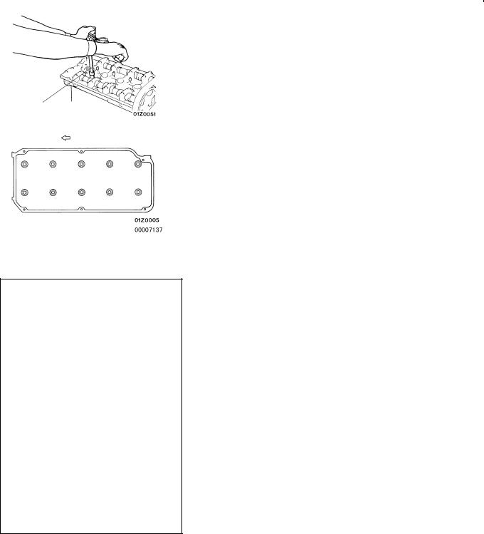
AB" CYLINDER HEAD BOLT REMOVAL
Use the special tool to loosen the bolts in two or three stages in the order of the numbers shown in the illustration, and then remove the bolts.
|
MB991653 |
|
|
|
|
Intake side |
|
Front of engine |
|
||
3 |
5 |
10 |
8 |
2 |
|
1 |
7 |
9 |
6 |
4 |
|
Exhaust side
INSTALLATION SERVICE POINTS
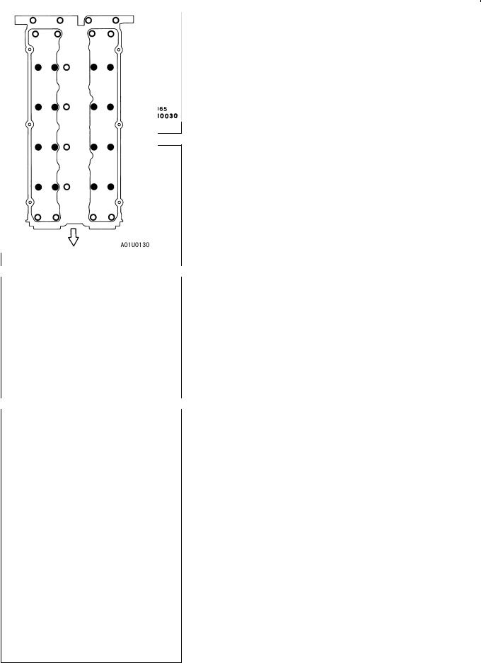
"AA CYLINDER HEAD GASKET INSTALLATION
1.Wipe off all oil and grease from the gasket mounting surface.
2.Install so that the shapes of the cylinder head holes match the shapes of the respective cylinder head gasket holes.

11A-14 |
ENGINE <4G9> – Cylinder Head Gasket |
|
|
|
|
Head bolt |
|
|
|
Burred side |
|
||
|
|
Head bolt |
|
|
(Engine |
A |
washer |
|
|
oil) |
|
|
|
|
|
||
|
|
Cylinder |
|
|
|
|
|
head |
|
|
|
|
|
|
|
|
|
|
|
|
|
|
|
|
|
|
|
|
|
|
MB991653 |
|
|
|
|
|
|
|
|
|
|
Intake side |
Front of engine |
|
|||
3 |
5 |
10 |
8 |
2 |
|
1 |
7 |
9 |
6 |
4 |
|
Exhaust side |
|
|
|
||
|
|
|
|
|
|
|
|
|
|
|
|
Step 4 |
|
|
Step 5 |
|
|
90_ |
|
|
|
90_ |
|
Painted mark |
|
Painted mark |
|||
|
|
|
|
|
|
"BA CYLINDER HEAD BOLT INSTALLATION
1.When installing the cylinder head bolts, the length below the head of the bolts should be within the limit.
If it is outside the limit, replace the bolts.
Limit (A): 96.4 mm
2.The head bolt washer should be installed with the burred side caused by tapping out facing upwards.
3.Apply a small amount of engine oil to the thread section and the washer of the cylinder head bolt.
4.Tighten the bolts by the following procedure.
Step |
Operation |
Remarks |
|
|
|
|
|
||
1 |
Tighten to 74 Nm. |
Carry out in the order |
||
|
|
shown in the illustration. |
||
|
|
|
||
2 |
Fully loosen. |
Carry out in the reverse |
||
|
|
order of that shown in the |
||
|
|
illustration. |
|
|
|
|
|
||
3 |
Tighten to 20 Nm. |
Carry out in the order |
||
|
|
shown in the illustration. |
||
|
|
|
||
4 |
Tighten 90_ of a turn. |
In the order shown in the |
||
|
|
illustration. |
Mark |
the |
|
|
head of the cylinder head |
||
|
|
bolt and cylinder head by |
||
|
|
paint. |
|
|
|
|
|
||
5 |
Tighten 90_ of a turn. |
In the order shown in the |
||
|
|
illustration. |
Check |
that |
|
|
the painted mark of the |
||
|
|
head bolt is lined up with |
||
|
|
that of the cylinder head. |
||
|
|
|
|
|
Caution
(1)Always make a tightening angle just 90_. If it is less than 90_, the head bolt will be loosened.
(2)If it is more than 90_, remove the head bolt and repeat the procedure from step 1.
ENGINE <4G9> – Engine Assembly |
11A-15 |
ENGINE ASSEMBLY
REMOVAL AND INSTALLATION
Pre-removal and Post-installation Operation
DEngine Cover Removal and Installation (Refer to P.11A-5.)
DPrevention of Fuel Discharge <before removal only>
DAir Bleeding the High Pressure Fuel Path <after installation only>
[Refer to GROUP 13A – Fuel Pump (High pressure).]
DFuel Leak Check <after installation only>
DDrive Belt Tension Adjustment
DUnder Cover Removal and Installation
DAir Cleaner Removal and Installation
DHood Removal and Installation
DRadiator Assembly Removal (Refer to GROUP 14.)
6 |
7 |
|
|
|
|
9.0 Nm |
|
7.0 Nm |
5 |
|
|
|
|
||
4 |
|
8 |
5.0 Nm |
|
|
||
2 |
|
|
11 |
9 |
|
|
14 |
3 |
|
|
|
1 |
5.0 Nm |
10 |
12 |
|
13 |
||
|
|
|
9.0 Nm
15
19
17 18
9.0 Nm
16
20
Removal steps
1.Crank angle sensor connector
2.Fuel pressure sensor
3.Oxygen sensor (front) connector
4.Control wiring harness and EGR wiring harness combination connector
5.Purge control solenoid valve connector
6.Throttle position sensor connector
7.Throttle valve control servo connector
8.Control wiring harness and injector wiring harness combination connector
9.Ignition coil connector
10.Ignition failure sensor connector
11.Camshaft position sensor connector
12.Engine coolant temperature sensor connector
13.Engine coolant temperature gauge unit connector
14.Detonation sensor connector
15.Power steering oil pressure switch connector
16.A/C compressor connector
17.Alternator connector
18.Engine oil pressure switch connector
19.Starter connector
20.Drive belt (Power steering and A/C)

11A-16 |
ENGINE <4G9> – Engine Assembly |
Caution
Mounting locations marked by * should be provisionally tightened, and then fully tightened when the body is supporting the full weight of the engine.
(Engine Oil)
23 |
24 |
|
28 |
26 |
27 |
|
|
|
|
5.0 Nm |
|
|
|
|
|
25
30
12 Nm
67 Nm
22 Nm
29
57 Nm
22 Nm |
21 |
|
22
98 – 118 Nm*
AA" 21. Power steering oil pump AB" 22. A/C compressor
23.Brake booster vacuum hose connection
24.Vacuum hose connection
25.Heater hoses connection
"DA 26. Fuel return hoses connection "CA 27. High-pressure fuel hose connection
"CA 28. O-ring
DTransmission assembly
(Refer to ’99 SPACE STAR Workshop
Manual.)
(Refer to GROUP 23. <A/T>) AC" "BA 29. Engine mount Bracket
AD" "AA 30. Engine assembly

ENGINE <4G9> – Engine Assembly |
11A-17 |
REMOVAL SERVICE POINTS
AA" POWER STEERING OIL PUMP REMOVAL
Remove the power steering oil pump from the engine with the hose attached.
NOTE
Place the removed power steering oil pump where it will not be a hindrance when removing and installing the engine assembly, and tie it with a cord.
AB" A/C COMPRESSOR REMOVAL
Disconnect the A/C compressor connector and remove the compressor from the compressor bracket with the hose still attached.
NOTE
Place the removed A/C compressor where it will not be a hindrance when removing and installing the engine assembly, and tie it with a cord.
|
|
|
|
|
AC" ENGINE MOUNT BRACKET REMOVAL |
|
|
|
|
MZ203827 |
|
||
|
|
|
|
|
|
|
|
|
|
|
|
1. |
Support the engine with a garage jack. |
|
MB991453 |
|
|
|
2. |
Remove the mechanical hanger (recommended tool) which |
|
|
|
|
|
|
was attached when the transmission assembly was |
|
|
|
|
|
|
removed. |
|
|
|
|
|
3. |
Hold the engine assembly with a chain block or similar |
|
|
|
|
|
|
tool. |
|
|
|
|
|
4. |
Place a garage jack against the engine oil pan with a |
|
|
|
|
|
|
piece of wood in between, jack up the engine so that |
|
|
|
|
|
|
the weight of the engine is no longer being applied to |
|
|
|
|
|
|
the engine mount bracket, and then remove the engine |
|
|
|
|
|
|
|
|
|
|
|
|
|
mount bracket. |
AD" ENGINE ASSEMBLY REMOVAL
After checking that all cables, hoses and harness connectors, etc., are disconnected from the engine, lift the chain block slowly to remove the engine assembly upward from the engine compartment.
INSTALLATION SERVICE POINTS
"AA ENGINE ASSEMBLY INSTALLATION
Install the engine assembly, checking that the cables, hoses, and harness connectors are not clamped.

11A-18 |
ENGINE <4G9> – Engine Assembly |
|
|
|
|
|
"BA ENGINE MOUNT BRACKET INSTALLATION |
|
|
|
|
MZ203827 |
|
||
|
|
|
|
|
|
|
|
|
|
|
|
1. |
Place a garage jack against the engine oil pan with a |
|
MB991453 |
|
|
|
|
piece of wood in between, and install the engine mount |
|
|
|
|
|
|
bracket while adjusting the position of the engine. |
|
|
|
|
|
2. |
Support the engine with the garage jack. |
|
|
|
|
|
3. |
Remove the chain block and support the engine assembly |
|
|
|
|
|
|
with the mechanical hanger (recommended tool). |
|
|
|
|
|
|
|
"CA O-RING/HIGH-PRESSURE FUEL HOSE
INSTALLATION
1.Apply a small amount of new engine oil to the O-ring.
Caution
Do not let any engine oil get into the delivery pipe.
2.While turning the high-pressure fuel hose to the right and left, install the delivery pipe, while being careful not to damage the O-ring. After installing, check that the hose turns smoothly.
3.If the hose does not turn smoothly, the O-ring is probably being clamped. Disconnect the high-pressure fuel hose and check the O-ring for damage. After this, re-insert the delivery pipe and check that the hose turns smoothly.
4.Tighten to the specified torque.
Specified torque: 5.0 Nm
"DA FUEL RETURN HOSES INSTALLATION
Install so that the identification marks of the fuel return hoses are at the positions shown in the illustration.
White mark
Blue mark

11B-1
ENGINE <4G1>
CONTENTS
GENERAL . . . . . . . . . . . . . . . . . . . . . . . . . . . . . . . . . |
2 |
Ignition Timing Check and Adjustment . . . . . . . . . |
. 4 |
|
Outline of Change . . . . . . . . . . . . . . . . . . . . . . . . . . . . |
2 |
Lash Adjuster Check . . . . . . . . . . . . . . . . . . . . . . . . . |
. 5 |
|
GENERAL INFORMATION . . . . . . . . . . . . . . . . . . |
2 |
CAMSHAFT AND CAMSHAFT OIL SEAL . . . . |
8 |
|
SERVICE SPECIFICATIONS . . . . . . . . . . . . . . . . . |
2 |
CRANKSHAFT FRONT OIL SEAL . . . . . . . . . . |
10 |
|
SEALANT . . . . . . . . . . . . . . . . . . . . . . . . . . . . . . . . . . |
2 |
CYLINDER HEAD GASKET . . . . . . . . . . . . . . . . |
12 |
|
SPECIAL TOOLS . . . . . . . . . . . . . . . . . . . . . . . . . . . |
3 |
ENGINE ASSEMBLY . . . . . . . . . . . . . . . . . . . . . . |
15 |
|
ON-VEHICLE SERVICE . . . . . . . . . . . . . . . . . . . . . |
4 |
|
|
|
|
|
|
|
|
|
|
|
|
|

11B-2 |
General/General Information/Service |
ENGINE <4G1> – Specifications/Sealant |
GENERAL
OUTLINE OF CHANGE
Since the catalytic converter internal-type exhaust manifold and the auto-lash adjuster are adopted, and intake manifold and the ignition system are changed, the following service adjustment procedures are made. Otherwise, the procedures are the same as that of the existing models.
GENERAL INFORMATION
Items |
4G13 |
|
|
Auto-lash adjuster |
Equipped |
|
|
SERVICE SPECIFICATIONS
Items |
Standard value |
Limit |
|
|
|
Basic ignition timing |
5_ BTDC ± 3_ |
– |
|
|
|
Cylinder head bolt shank length mm |
– |
103.2 |
|
|
|
SEALANT
Items |
Specified sealant |
Remarks |
|
|
|
Camshaft position sensor support |
MITSUBISHI GENUINE PART |
Semi-drying sealant |
|
MD970389 or equivalent |
|
|
|
|

|
|
ENGINE <4G1> – Special Tools |
11B-3 |
|||
SPECIAL TOOLS |
|
|
|
|
|
|
|
|
|
|
|
|
|
Tool |
|
Number |
Name |
|
Use |
|
|
|
|
|
|
|
|
|
|
MB991502 |
MUT-II sub |
|
D Measuring the drive belt tension |
|
|
|
|
assembly |
|
D Checking the idle speed |
|
|
|
|
|
|
|
|
|
|
MB991668 |
Belt tension meter |
Measuring the drive belt tension |
|
|
|
|
|
set |
|
(used together with MUT-II) |
|
|
|
|
|
|
|
|
|
|
MD998747 |
Crankshaft |
pulley |
Holding the crankshaft pulley |
|
|
|
|
holder |
|
|
|
|
|
|
|
|
|
|
|
|
MB990767 |
End yoke holder |
Holding the camshaft sprocket |
|
|
|
|
|
|
|
|
|
|
|
MD998719 or |
Crankshaft |
pulley |
|
|
|
|
MD998754 |
holder pin |
|
|
|
|
|
|
|
|
|
|
|
|
MD998713 |
Camshaft |
oil seal |
Press-in of the camshaft oil seal |
|
|
|
|
installer |
|
|
|
|
|
|
|
|
|
|
|
|
MD998727 |
Oil pan remover |
Removing the oil pan |
|
|
|
|
|
|
|
|
|
|
|
MD998781 |
Fly wheel stopper |
Securing the flywheel |
|
|
|
|
|
|
|
||
|
|
MD998718 |
Crankshaft rear oil |
Press-fitting the crankshaft rear oil seal |
||
|
|
|
seal installer |
|
|
|
|
|
|
|
|
|
|

11B-4 |
ENGINE <4G1> – Special Tools/On-vehicle Service |
|||
|
|
|
|
|
Tool |
|
Number |
Name |
Use |
|
|
|
|
|
A |
|
A: MD998304 |
A: Crankshaft front |
Press-fitting the crankshaft front oil seal |
|
B: MD998305 |
oil seal installer |
|
|
|
|
|
||
|
|
|
B: Crankshaft front |
|
|
B |
|
oil seal guide |
|
|
|
|
|
|
|
|
|
|
|
|
|
MB991653 |
Cylinder head bolt |
Cylinder head bolt removal and installation |
|
|
|
wrench |
|
|
|
|
|
|
|
|
GENERAL |
Engine lifter |
Supporting the engine assembly during |
|
|
SERVICE |
|
removal and installation of the transmission |
|
|
TOOL |
|
|
|
|
MZ203827 |
|
|
|
|
|
|
|
|
|
MB991453 |
Engine hanger as- |
|
|
|
|
sembly |
|
|
|
|
|
|
ON-VEHICLE SERVICE
IGNITION TIMING CHECK
1.Set the vehicle to the pre-inspection condition.
2.After turning the ignition switch to the LOCK (OFF) position, connect the MUT-II to the diagnosis connector.
3.Connect a timing light.
4.Start the engine and run it at idle.
5.Select item No. 22 on the MUT-II and take a reading of the engine speed. Check that the idle speed is at the standard value.
Standard value: 750 ± 100 r/min
6.Select item No. 17 (actuator test function) on the MUT-II, and set the ignition timing to the basic ignition timing.
7.Check the basic ignition timing.
Standard value: 5_ BTDC ± 3_
8.If the basic ignition timing is outside the standard value range, check the MPI system while referring to GROUP 13B
– Troubleshooting.
9.Press the CLEAR key on the MUT-II to cancel the basic ignition timing setting mode by the actuator test function.
Caution
If the mode is not cancelled, the basic ignition timing setting mode will remain active for 27 minutes, and problems with engine operation may result if the vehicle is driven during this period.

ENGINE <4G1> – On-vehicle Service |
11B-5 |
10.Check that the ignition timing is at the standard ignition timing.
Standard value: Approx. 10_ BTDC
NOTE
(1)There should be no problems if the ignition timing varies within a range of about 7_.
(2)At high altitudes, advance the ignition timing by about a further 5_ from the standard value.
LASH ADJUSTER CHECK
If an abnormal noise (knocking) that seems to be coming from the lash adjuster is heard after starting the engine and does not stop, carry out the following check.
NOTE
(1)The abnormal noise which is caused by a problem with the lash adjusters is generated after the engine is started, and will vary according to the engine speed. However, this noise is not related to the actual engine load.
Because of this, if the noise does not occur immediately after the engine is started, if it does not change in accordance with the engine speed, or if it changes in accordance with the engine load, the source of the noise is not the lash adjusters.
(2)If there is a problem with the lash adjusters, the noise will almost never disappear, even if the engine has been run at idle to let it warm up.
The only case where the noise might disappear is if the oil in the engine has not been looked after properly and oil sludge has caused the lash adjusters to stick.
1.Start the engine.
2.Check that the noise occurs immediately after the engine is started, and that the noise changes in accordance with changes in the engine speed.
If the noise does not occur immediately after the engine is started, or if it does not change in accordance with the engine speed, the problem is not being caused by the lash adjusters, so check for some other cause of the problem. Moreover, if the noise does not change in accordance with the engine speed, the cause of the problem is probably not with the engine. (In these cases, the lash adjusters are normal.)

11B-6 |
ENGINE <4G1> – On-vehicle Service |
3.While the engine is idling, check that the noise level does not change when the engine load is varied.
If the noise level changes, the cause of the noise is probably parts striking because of worn crankshaft bearings or connecting rod bearings. (In such cases, the lash adjusters are normal.)
4.After the engine has warmed up, run it at idle and check if any noise can be heard.
If the noise has become smaller or disappeared, oil sludge could make the lash adjusters stick. Clean the lash adjusters. (Refer to the Engine Workshop Manual.) If not improved, go to step 5.
5.Bleed air from the lash adjusters.
6.If the noise has not disappeared even after the air bleeding, clean the lash adjusters. (Refer to the Engine Workshop Manual.)
<LASH ADJUSTER AIR BLEEDING>
NOTE
(1)If the vehicle is parked on a slope for a long period of time, the amount of oil inside the lash adjuster will decrease, and air may get into the high pressure chamber when starting the engine.
(2)After parking the vehicle for long periods, the oil drains out of the oil passage, and it takes time for the oil to be supplied to the lash adjuster, so air can get into the high pressure chamber.
(3)If either of the above situations occur, the abnormal noise can be eliminated by bleeding the air from inside the lash adjusters.
1.Check the engine oil and replenish or replace the oil if necessary.
NOTE
(1)If there is a only small amount of oil, air will be drawn in through the oil screen and will get into the oil passage.
(2)If the amount of oil is greater than normal, then the oil will being mixed by the crankshaft and a large
Good |
amount of air may get mixed into the oil. |
|
(3) |
If the oil is degenerated, air and oil will not separate |
|
|
|
easily in oil, and the amount of air mixed into the |
|
|
|
|
|
oil will increase. |
 Loading...