


 Loading...
MITSUBISHI ELECTRIC SERVO SYSTEM CONTROLLER
Migration Guide from Positioning Module to Simple Motion Module [QD74MH RD77MS]

● SAFETY PRECAUTIONS ●
(Read these precautions before using this product.)
Before using this product, please read this manual and the relevant manuals carefully and pay full attention to safety to handle the product correctly.
The precautions given in this manual are concerned with this product only. Refer to the MELSEC iQ-R Module Configuration Manual for a description of the PLC system safety precautions.
In this manual, the safety precautions are classified into two levels: “ WARNING” and “
 CAUTION”.

 WARNING

 CAUTION
Indicates that incorrect handling may cause hazardous conditions, resulting in death or severe injury.
Indicates that incorrect handling may cause hazardous conditions, resulting in minor or moderate injury or property damage.
Under some circumstances, failure to observe the precautions given under “ CAUTION” may lead to serious consequences.
Observe the precautions of both levels because they are important for personal and system safety. Make sure that the end users read this manual and then keep the manual in a safe place for future reference.
A - 1

[Design Precautions]
 WARNING
●Configure safety circuits external to the programmable controller to ensure that the entire system operates safely even when a fault occurs in the external power supply or the programmable controller.
Failure to do so may result in an accident due to an incorrect output or malfunction.
(1)Emergency stop circuits, protection circuits, and protective interlock circuits for conflicting operations (such as forward/reverse rotations or upper/lower limit positioning) must be configured external to the programmable controller.
(2)When the programmable controller detects an abnormal condition, it stops the operation and all outputs are:
•Turned off if the overcurrent or overvoltage protection of the power supply module is activated.
•Held or turned off according to the parameter setting if the self-diagnostic function of the CPU module detects an error such as a watchdog timer error.
(3)All outputs may be turned on if an error occurs in a part, such as an I/O control part, where the CPU module cannot detect any error. To ensure safety operation in such a case, provide a safety mechanism or a fail-safe circuit external to the programmable controller. For a fail-safe circuit example, refer to "General Safety Requirements" in the MELSEC iQ-R Module Configuration Manual.
(4)Outputs may remain on or off due to a failure of a component such as a relay and transistor in an output circuit. Configure an external circuit for monitoring output signals that could cause a serious accident.
●In an output circuit, when a load current exceeding the rated current or an overcurrent caused by a load short-circuit flows for a long time, it may cause smoke and fire. To prevent this, configure an external safety circuit, such as a fuse.
●Configure a circuit so that the programmable controller is turned on first and then the external power supply. If the external power supply is turned on first, an accident may occur due to an incorrect output or malfunction.
●For the operating status of each station after a communication failure, refer to manuals relevant to the network. Incorrect output or malfunction due to a communication failure may result in an accident.
●When connecting an external device with a CPU module or intelligent function module to modify data of a running programmable controller, configure an interlock circuit in the program to ensure that the entire system will always operate safely. For other forms of control (such as program modification, parameter change, forced output, or operating status change) of a running programmable controller, read the relevant manuals carefully and ensure that the operation is safe before proceeding. Improper operation may damage machines or cause accidents.
●Especially, when a remote programmable controller is controlled by an external device, immediate action cannot be taken if a problem occurs in the programmable controller due to a communication failure. To prevent this, configure an interlock circuit in the program, and determine corrective actions to be taken between the external device and CPU module in case of a communication failure.
A - 2

[Design Precautions]
 WARNING
●Do not write any data to the "system area" and "write-protect area" of the buffer memory in the module. Also, do not use any "use prohibited" signals as an output signal from the CPU module to each module. Doing so may cause malfunction of the programmable controller system. For the "system area", "write-protect area", and the "use prohibited" signals, refer to the user's manual for the module used.
●If a communication cable is disconnected, the network may be unstable, resulting in a communication failure of multiple stations. Configure an interlock circuit in the program to ensure that the entire system will always operate safely even if communications fail. Failure to do so may result in an accident due to an incorrect output or malfunction.
●To maintain the safety of the programmable controller system against unauthorized access from external devices via the network, take appropriate measures. To maintain the safety against unauthorized access via the Internet, take measures such as installing a firewall.
●Configure safety circuits external to the programmable controller to ensure that the entire system operates safely even when a fault occurs in the external power supply or the programmable controller. Failure to do so may result in an accident due to an incorrect output or malfunction.
(1)Machine home position return is controlled by two kinds of data: a home position return direction and a home position return speed. Deceleration starts when the proximity dog signal turns on. If an incorrect home position return direction is set, motion control may continue without deceleration. To prevent machine damage caused by this, configure an interlock circuit external to the programmable controller.
(2)When the module detects an error, the motion slows down and stops or the motion rapidly stops, depending on the stop group setting in parameter. Set the parameter to meet the specifications of a positioning control system. In addition, set the home position return parameter and positioning data within the specified setting range.
(3)Outputs may remain on or off, or become undefined due to a failure of a component such as an insulation element and transistor in an output circuit, where the module cannot detect any error. In a system that the incorrect output could cause a serious accident, configure an external circuit for monitoring output signals.
●If safety standards (ex., robot safety rules, etc.,) apply to the system using the module, servo amplifier and servomotor, make sure that the safety standards are satisfied.
●Construct a safety circuit externally of the module or servo amplifier if the abnormal operation of the module or servo amplifier differs from the safety directive operation in the system.
●Do not remove the SSCNETIII cable while turning on the control circuit power supply of the module and servo amplifier. Do not see directly the light generated from SSCNETIII connector of the module or servo amplifier and the end of SSCNETIII cable. When the light gets into eyes, you may feel something wrong with eyes. (The light source of SSCNETIII complies with class1 defined in JISC6802 or IEC60825-1.)
A - 3

[Design Precautions]
 WARNING
●Do not install the control lines or communication cables together with the main circuit lines or power cables. Keep a distance of 100 mm or more between them. Failure to do so may result in malfunction due to noise.
●During control of an inductive load such as a lamp, heater, or solenoid valve, a large current (approximately ten times greater than normal) may flow when the output is turned from off to on. Therefore, use a module that has a sufficient current rating.
●After the CPU module is powered on or is reset, the time taken to enter the RUN status varies depending on the system configuration, parameter settings, and/or program size. Design circuits so that the entire system will always operate safely, regardless of the time.
●Do not power off the programmable controller or reset the CPU module while the settings are being written. Doing so will make the data in the flash ROM and SD memory card undefined. The values need to be set in the buffer memory and written to the flash ROM and SD memory card again. Doing so also may cause malfunction or failure of the module.
●When changing the operating status of the CPU module from external devices (such as the remote RUN/STOP functions), select "Do Not Open in Program" for "Opening Method Setting" in the module parameters. If "Open in Program" is selected, an execution of the remote STOP function causes the communication line to close. Consequently, the CPU module cannot reopen the communication line, and external devices cannot execute the remote RUN functions.
A - 4

[Installation Precautions]
 WARNING
●Shut off the external power supply (all phases) used in the system before mounting or removing the module. Failure to do so may result in electric shock or cause the module to fail or malfunction.
[Installation Precautions]
 CAUTION
●Use the programmable controller in an environment that meets the general specifications in the Safety Guidelines included with the base unit. Failure to do so may result in electric shock, fire, malfunction, or damage to or deterioration of the product.
●To mount a module, place the concave part(s) located at the bottom onto the guide(s) of the base unit, and push in the module until the hook(s) located at the top snaps into place. Incorrect interconnection may cause malfunction, failure, or drop of the module.
●To mount a module with no module fixing hook, place the concave part(s) located at the bottom onto the guide(s) of the base unit, push in the module, and fix it with screw(s). Incorrect interconnection may cause malfunction, failure, or drop of the module.
●When using the programmable controller in an environment of frequent vibrations, fix the module with a screw.
●Tighten the screws within the specified torque range. Undertightening can cause drop of the screw, short circuit, or malfunction. Overtightening can damage the screw and/or module, resulting in drop, short circuit, or malfunction.
●When using an extension cable, connect it to the extension cable connector of the base unit securely. Check the connection for looseness. Poor contact may cause malfunction.
●When using an SD memory card, fully insert it into the SD memory card slot. Check that it is inserted completely. Poor contact may cause malfunction.
●Securely insert an extended SRAM cassette into the cassette connector of the CPU module. After insertion, close the cassette cover and check that the cassette is inserted completely. Poor contact may cause malfunction.
●Do not directly touch any conductive parts and electronic components of the module, SD memory card, extended SRAM cassette, or connector. Doing so can cause malfunction or failure of the module.
[Wiring Precautions]
 WARNING
●Shut off the external power supply (all phases) used in the system before installation and wiring. Failure to do so may result in electric shock or cause the module to fail or malfunction.
●After installation and wiring, attach the included terminal cover to the module before turning it on for operation. Failure to do so may result in electric shock.
A - 5

[Wiring Precautions]
●Individually ground the FG and LG terminals of the programmable controller with a ground resistance of 100 ohms or less. Failure to do so may result in electric shock or malfunction.
●Use applicable solderless terminals and tighten them within the specified torque range. If any spade solderless terminal is used, it may be disconnected when the terminal screw comes loose, resulting in failure.
●Check the rated voltage and signal layout before wiring to the module, and connect the cables correctly. Connecting a power supply with a different voltage rating or incorrect wiring may cause fire or failure.
●Connectors for external devices must be crimped or pressed with the tool specified by the manufacturer, or must be correctly soldered. Incomplete connections may cause short circuit, fire, or malfunction.
●Securely connect the connector to the module. Poor contact may cause malfunction.
●Do not install the control lines or communication cables together with the main circuit lines or power cables. Keep a distance of 100 mm or more between them. Failure to do so may result in malfunction due to noise.
●Place the cables in a duct or clamp them. If not, dangling cable may swing or inadvertently be pulled, resulting in damage to the module or cables or malfunction due to poor contact. Do not clamp the extension cables with the jacket stripped. Doing so may change the characteristics of the cables, resulting in malfunction.
●Check the interface type and correctly connect the cable. Incorrect wiring (connecting the cable to an incorrect interface) may cause failure of the module and external device.
●Tighten the terminal screws or connector screws within the specified torque range. Undertightening can cause drop of the screw, short circuit, fire, or malfunction. Overtightening can damage the screw and/or module, resulting in drop, short circuit, fire, or malfunction.
●When disconnecting the cable from the module, do not pull the cable by the cable part. For the cable with connector, hold the connector part of the cable. For the cable connected to the terminal block, loosen the terminal screw. Pulling the cable connected to the module may result in malfunction or damage to the module or cable.
●Prevent foreign matter such as dust or wire chips from entering the module. Such foreign matter can cause a fire, failure, or malfunction.
●A protective film is attached to the top of the module to prevent foreign matter, such as wire chips, from entering the module during wiring. Do not remove the film during wiring. Remove it for heat dissipation before system operation.
●Programmable controllers must be installed in control panels. Connect the main power supply to the power supply module in the control panel through a relay terminal block. Wiring and replacement of a power supply module must be performed by qualified maintenance personnel with knowledge of protection against electric shock. For wiring, refer to the MELSEC iQ-R Module Configuration Manual.
●For Ethernet cables to be used in the system, select the ones that meet the specifications in the user's manual for the module used. If not, normal data transmission is not guaranteed.
A - 6

[Startup and Maintenance Precautions]
 WARNING
●Do not touch any terminal while power is on. Doing so will cause electric shock or malfunction.
●Correctly connect the battery connector. Do not charge, disassemble, heat, short-circuit, solder, or throw the battery into the fire. Also, do not expose it to liquid or strong shock. Doing so will cause the battery to produce heat, explode, ignite, or leak, resulting in injury and fire.
●Shut off the external power supply (all phases) used in the system before cleaning the module or retightening the terminal screws, connector screws, or module fixing screws. Failure to do so may result in electric shock.
[Startup and Maintenance Precautions]
 CAUTION
●When connecting an external device with a CPU module or intelligent function module to modify data of a running programmable controller, configure an interlock circuit in the program to ensure that theentire system will always operate safely. For other forms of control (such as program modification, parameter change, forced output, or operating status change) of a running programmable controller, read the relevant manuals carefully and ensure that the operation is safe before proceeding. Improper operation may damage machines or cause accidents.
●Especially, when a remote programmable controller is controlled by an external device, immediate action cannot be taken if a problem occurs in the programmable controller due to a communication failure. To prevent this, configure an interlock circuit in the program, and determine corrective actions to be taken between the external device and CPU module in case of a communication failure.
●Do not disassemble or modify the modules. Doing so may cause failure, malfunction, injury, or a fire.
●Use any radio communication device such as a cellular phone or PHS (Personal Handy-phone System) more than 25 cm away in all directions from the programmable controller. Failure to do so may cause malfunction.
A - 7

[Startup and Maintenance Precautions]
 CAUTION
●Shut off the external power supply (all phases) used in the system before mounting or removing the module. Failure to do so may cause the module to fail or malfunction.
●Tighten the screws within the specified torque range. Undertightening can cause drop of the component or wire, short circuit, or malfunction. Overtightening can damage the screw and/or module, resulting in drop, short circuit, or malfunction.
●After the first use of the product, do not mount/remove the module to/from the base unit, and the terminal block to/from the module, and do not insert/remove the extended SRAM cassette to/from the CPU module more than 50 times (IEC 61131-2 compliant) respectively. Exceeding the limit may cause malfunction.
●After the first use of the product, do not insert/remove the SD memory card to/from the CPU module more than 500 times. Exceeding the limit may cause malfunction.
●Do not touch the metal terminals on the back side of the SD memory card. Doing so may cause malfunction or failure of the module.
●Do not touch the integrated circuits on the circuit board of an extended SRAM cassette. Doing so may cause malfunction or failure of the module.
●Do not drop or apply shock to the battery to be installed in the module. Doing so may damage the battery, causing the battery fluid to leak inside the battery. If the battery is dropped or any shock is applied to it, dispose of it without using.
●Startup and maintenance of a control panel must be performed by qualified maintenance personnel with knowledge of protection against electric shock. Lock the control panel so that only qualified maintenance personnel can operate it.
●Before handling the module, touch a conducting object such as a grounded metal to discharge the static electricity from the human body. Failure to do so may cause the module to fail or malfunction.
●Before testing the operation, set a low speed value for the speed limit parameter so that the operation can be stopped immediately upon occurrence of a hazardous condition.
●Confirm and adjust the program and each parameter before operation. Unpredictable movements may occur depending on the machine.
●When using the absolute position system function, on starting up, and when the module or absolute position motor has been replaced, always perform a home position return.
●Before starting the operation, confirm the brake function.
●Do not perform a megger test (insulation resistance measurement) during inspection.
●After maintenance and inspections are completed, confirm that the position detection of the absolute position detection function is correct.
●Lock the control panel and prevent access to those who are not certified to handle or install electric equipment.
A - 8
[Operating Precautions]
 CAUTION
●When changing data and operating status, and modifying program of the running programmable controller from an external device such as a personal computer connected to an intelligent function module, read relevant manuals carefully and ensure the safety before operation. Incorrect change or modification may cause system malfunction, damage to the machines, or accidents.
●Do not power off the programmable controller or reset the CPU module while the setting values in the buffer memory are being written to the flash ROM in the module. Doing so will make the data in the flash ROM and SD memory card undefined. The values need to be set in the buffer memory and written to the flash ROM and SD memory card again. Doing so also may cause malfunction or failure of the module.
●Note that when the reference axis speed is specified for interpolation operation, the speed of the partner axis (2nd, 3rd, or 4th axis) may exceed the speed limit value.
●Do not go near the machine during test operations or during operations such as teaching. Doing so may lead to injuries.
[Disposal Precautions]
 CAUTION
●When disposing of this product, treat it as industrial waste.
●When disposing of batteries, separate them from other wastes according to the local regulations. For details on battery regulations in EU member states, refer to the MELSEC iQ-R Module Configuration Manual.
[Transportation Precautions]
 CAUTION
●When transporting lithium batteries, follow the transportation regulations. For details on the regulated models, refer to the MELSEC iQ-R Module Configuration Manual.
●The halogens (such as fluorine, chlorine, bromine, and iodine), which are contained in a fumigant used for disinfection and pest control of wood packaging materials, may cause failure of the product. Prevent the entry of fumigant residues into the product or consider other methods (such as heat treatment) instead of fumigation. The disinfection and pest control measures must be applied to unprocessed raw wood.
A - 9

REVISIONS
Print Date |
Manual No. |
Revision |
Sep., 2018 |
L(NA)03170ENG-A |
First edition |
|
|
|
This manual confers no industrial property rights or any rights of any other kind, nor does it confer any patent licenses. Mitsubishi Electric Corporation cannot be held responsible for any problems involving industrial property rights which may occur as a result of using the contents noted in this manual.
2018 MITSUBISHI ELECTRIC CORPORATION
A - 10
INTRODUCTION |
|
Please read this manual carefully so that equipment is used to its optimum. |
|
CONTENTS |
|
Safety Precautions......................................................................................................................................... |
A- 1 |
Revisions····························································································································A-10
Contents·····························································································································A-11
1. OVERVIEW OF MIGRATION FROM QD74MH TO RD77MS |
1- 1 to 1-14 |
1.1Benefits of Migration········································································································1- 1
1.2Main Target Models for Migration·······················································································1- 2
1.3System Configuration······································································································1- 4
1.3.1System configuration using QD74MH before migration·····················································1- 4
1.3.2System configuration using RD77MS after migration························································1- 4
1.4 Case Study on Migration··································································································1- 5
1.4.1Whole system migration (recommended)·······································································1- 6
1.4.2Phased migration······································································································1- 7
1.4.3Separate repair·········································································································1- 8
1.5Project Diversion············································································································1-10
1.6Relevant Documents·······································································································1-11
1.6.1Relevant catalogs ·····································································································1-11
1.6.2Relevant manuals ·····································································································1-12
2. DETAILS OF MIGRATION FROM QD74MH TO RD77MS |
2- 1 to 2- 32 |
2.1Table of Components and Software ···················································································2- 1
2.1.1Servo amplifiers and servo motors················································································2- 2
2.1.2Engineering environment (required)··············································································2- 3
2.2Differences Between QD74MH and RD77MS·······································································2- 4
2.3Forced Stop Input Cable ··································································································2-17
2.4Project Diversion ············································································································2-20
2.4.1Project diversion procedures by engineering environment·················································2-20
2.4.2List of divertible/not divertible data·················································································2-24
A - 11

MEMO
A - 12

1. OVERVIEW OF MIGRATION FROM QD74MH TO RD77MS
1. OVERVIEW OF MIGRATION FROM QD74MH TO RD77MS
1
1.1 Benefits of Migration
Migrating from the existing system using QD74MH Positioning modules to a new system using MELSEC iQ-R series Simple Motion module RD77MS16/RD77MS8 (hereinafter called RD77MS) is recommended. We also recommend migrating servo amplifiers to the MR-J4 series at the same time.
Migrating not only allows the system to run for longer periods, but also has the following advantages.
(1)High functionality of Positioning module (Simple Motion module)
The Simple Motion module achieves further advanced motion control with a wide variety of motion control functions such as synchronous control, in addition to positioning control. The replaced model offers various new auxiliary features including cam detection function and cam auto generation function, helping to reduce programming time further.
→Increased productivity from higher functionality of the controller
(2)High-speed communication by SSCNETIII/H 
Speeding up and improving noise tolerance of servo system network communications are achieved by optical communication. A long distance cable of 100 m can be also used.
→Increased speeds over the entire facility
(3)Servo amplifier MR-J4 and servo motor 
The MR-J4 series achieves high performance operation with a variety of functions including one-touch tuning, a 22-bit high resolution encoder (4194304 pulse/rev), and 2.5 kHz speed frequency response. The product lineup includes multi-axis servo amplifiers that contribute to energy saving, space saving, and reduced wiring of a machine. The MR-J4 series compatible rotary servo motor, HG series enables to output high torque at high speed. Linear servo motors and direct drive motors are also available. Select the motor type according to your application from our extensive product lineup.
→Increase of applications, improved performance, energy saving, downsizing, and reduced wiring of drive systems
(4)Reliable monitoring functions
With our engineering software, the system status is easily monitored just by selecting monitoring items that your system needs from its wealth of monitoring information.
In addition, operation is checked through waveforms and each device data collected by digital oscilloscope and GX Logviewer
→A strong support for troubleshooting
(5)Lower maintenance cost
After 5 years of usage, the products will need maintenance, such as replacement of the whole circuit board due to the life of components including electrolytic capacitors and memories. To use the system the longest possible, an early migration to the latest model is recommended in terms of performance and quality.
→Increased equipment longevity
1 - 1
1.OVERVIEW OF MIGRATION FROM QD74MH TO RD77MS
1.2Main Target Models for Migration
The main target models for replacement described in this section are as follows.
(1) Positioning modules
Product name |
Model |
Model |
|
before migration |
after migration |
||
|
|||
SSCNETIII compatible |
QD74MH8 |
RD77MS8 |
|
Positioning module |
QD74MH16 |
RD77MS16 |
(2)Servo amplifiers and servo motors
The existing MR-J3 series servo amplifiers can be used in the migrated system with RD77MS, however, it is strongly recommended to replace them with the MR-J4 series.
(a) Servo amplifiers and rotary servo motors
|
Before migration from QD74MH |
|
|
After migration to RD77MS |
||||
|
Servo amplifier |
Rotary |
|
|
Servo amplifier |
Rotary |
||
|
servo motor |
|
|
servo motor |
||||
|
|
|
|
|
|
|
||
MR-J3 |
|
MR-J3- B |
HF-KP |
|
MR-J4 |
|
MR-J4- B(-RJ) |
HG-KR |
series |
|
MR-J3W- B |
HF-MP |
|
series |
|
MR-J4W2- B |
HG-MR |
|
|
MR-J3- BS |
HF-SP |
|
|
|
MR-J4W3- B |
HG-SR |
|
|
MR-J3- B-RJ006 |
HF-JP |
|
|
|
|
HG-RR |
|
|
|
HC-LP |
|
|
|
|
HG-UR |
|
|
|
HC-RP |
|
|
|
|
HG-JR |
|
|
|
HC-UP |
|
|
|
|
|
|
|
|
HA-LP |
|
|
|
|
|
(b) Servo amplifiers and linear servo motors
|
Before migration from QD74MH |
|
After migration to RD77MS |
||
|
Servo amplifier |
Linear |
|
Servo amplifier |
Linear |
|
servo motor |
|
servo motor |
||
|
|
|
|
||
MR-J3 |
MR-J3- B-RJ004 |
LM-H2 |
MR-J4 |
MR-J4- B(-RJ) |
LM-H3 |
series |
|
LM-F |
series |
MR-J4W2- B |
LM-F |
|
|
LM-K2 |
|
MR-J4W3- B |
LM-K2 |
|
|
LM-U2 |
|
|
LM-U2 |
1 - 2

1.OVERVIEW OF MIGRATION FROM QD74MH TO RD77MS
(3)Servo system network
Item
Communications medium
Communications speed
Communications Send cycle Receive
Number of control axes
Transmission distance
Optical fiber cable
50Mbps
0.44ms/0.88 ms
0.44ms/0.88 ms
Up to 16 axes/line
[Standard code for inside panel] Up to 3 m between stations Maximum overall distance: 48 m (3 m × 16 axes)
[Standard cable for outside panel] Up to 20 m between stations Maximum overall distance: 320 m (20 m × 16 axes)
[Long distance cable]
Up to 50 m between stations Maximum overall distance: 800 m (50 m × 16 axes)
← (same as SSCNETIII)
150 Mbps
0.222 ms/0.444 ms/0.888 ms
0.222 ms/0.444 ms/0.888 ms
← (same as SSCNETIII)
[Standard code for inside panel and standard cable for outside panel]
Up to 20 m between stations
Maximum overall distance: 320 m (20 m × 16 axes)
[Long distance cable]
Up to 100 m between stations
Maximum overall distance: 1600 m (100 m × 16 axes)
(4) Engineering environment (required)
Product name |
Model |
Version |
MELSOFT GX Works3 |
SW1DND-GXW3-E |
Ver.1.046Y or later |
MELSOFT MR Configurator2 |
SW1DNC-MRC2-E |
Ver.1.27D or later |
1 - 3
1.OVERVIEW OF MIGRATION FROM QD74MH TO RD77MS
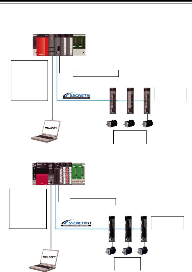
1.3System Configuration
1.3.1 System configuration using QD74MH before migration
Main base unit Q3
 B
B
Power supply module Q6 P
P
PLC CPU module Qn(H)CPU Positioning module QD74MH
USB communication cable or RS-232 communication cable
Forced stop input cable Q170DEMICBL M
M
 Forced stop input (24 VDC)
SSCNETIII cable
MR-J3BUS M(-A/-B)
Servo amplifier MR-J3-B
Servo motor
HC/HA/HF series
1.3.2 System configuration using RD77MS after migration
Main base unit R3 B
B
Power supply module R6
 P
P
PLC CPU module RnCPU
Simple Motion module RD77MS
USB communication cable or Ethernet communication cable
External input signal cable (Note-1)
 Forced stop input (24 VDC)
SSCNETIII cable MR-J3BUS M(-A/-B)
Servo amplifier MR-J4-B
Servo motor
HG series
(Note-1): Replace the forced stop input cable for the new controller. (Refer to section 1.4.2.)
1 - 4

1.OVERVIEW OF MIGRATION FROM QD74MH TO RD77MS
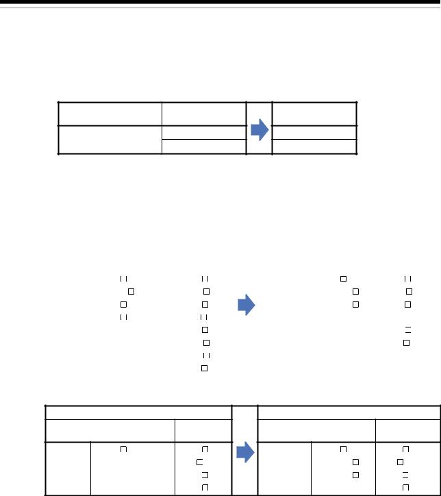
1.4Case Study on Migration
The following describes a case study for migrating the existing system using QD74MH.
|
Consideration of migration |
|
|
|
|
|
Whole system |
NO |
|
|
|
|
migration? |
|
|
|
|
|
YES |
|
|
|
|
|
|
|
Phased |
|
NO |
|
|
|
migration? |
|
|
|
|
|
YES |
|
|
|
|
|
|
|
|
|
|
|
|
||
(1) Whole system migration |
|
(2) Phased migration |
|
(3) Separate repair |
|
|
→ Refer to section 1.4.1. |
|
→ Refer to section 1.4.2. |
|
→ Refer to section 1.4.3. |
|
|
|
|
|
|
(1)Whole system migration (recommended)
The controller, servo amplifiers, servo motors, and servo system network are replaced simultaneously. Although a large-scale installation is required, the whole system migration allows the system to operate for longer periods. (Refer to section 1.4.1.)
(2)Phased migration (When the whole system migration is difficult due to the installation period and cost.)
The controller is replaced with RD77MS in the first phase, and then the MR-J3-B servo amplifiers are gradually replaced with MR-J4-B.
(Refer to section 1.4.2.)
(3)Separate repair
This is a replacement method for when the controller, the servo amplifier, or the servo motor malfunctions.
(Refer to section 1.4.3.)
1 - 5

1. OVERVIEW OF MIGRATION FROM QD74MH TO RD77MS
1.4.1 Whole system migration (recommended)
The following shows the system when the whole system migration takes place.
[Current model] QD74MH |
[Model after migration] RD77MS |
|
|
|
|
|
|
|
|
|
|
|
|
|
|
|
|
Forced stop input |
|
|
|
|
|
Forced stop input |
|||||
|
|
|
|
||||||||||
|
|
|
|
|
|
|
|
|
|
|
|
|
|
|
|
|
|
|
|
|
|
|
|
|
|
|
|
|
|
|
|
|
|
|
|
|
|
|
|
|
|
MR-J3-B |
MR-J4-B |
HC/HA/HF |
|
HG |
servo motor |
|
servo motor |
|
|
|
[Changes in the system]
Product name |
Model before migration |
|
Model after migration |
Main base unit |
Q3 B |
|
R3 B |
PLC CPU module |
Qn(H)CPU |
|
RnCPU |
Positioning module |
QD74MH |
|
RD77MS |
Servo amplifier |
MR-J3-B |
|
MR-J4-B |
Servo motor |
HC/HA/HF series |
|
HG series |
|
|
|
Fabricate the cable with |
Forced stop input cable |
Q170DEMICBL M |
|
A6CON connector. |
|
|
|
(Refer to section 2.3.) |
1 - 6
Loading...