


Mitsubishi Electronics PUH36EK, PUH18EK, PKH30FK, PKH36FK, PUH24EK User Manual
...SPLIT-TYPE,HEAT PUMP AIR CONDITIONERS
No. OC120
TECHNICAL & SERVICE MANUAL
Series PKH Wall Mounted
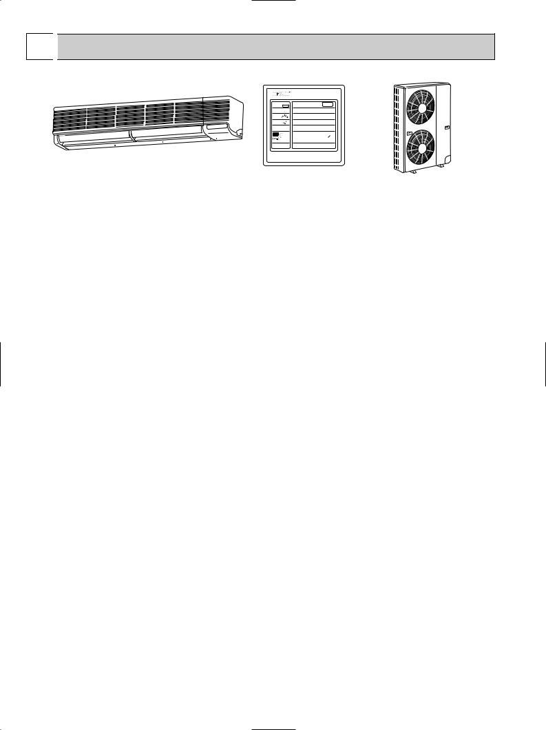
<Indoor unit>
Models PKH18FK / PUH18EK
PKH24FK / PUH24EK
PKH30FK / PUH30EK
PKH36FK / PUH36EK
Indoor unit
-CENTRALLY CONTROLLED- |
|
POWER |
ON/OFF |
||
STAND BY |
ON |
|
|||
DEFROST |
|
|
|
||
CHECK DRY |
HEAT |
AUTO |
COOL/DRY |
||
HEAT |
COOL |
||||
|
|
|
|||
CHECK |
F |
SET |
WARMER |
COOLER |
|
SET TEMP |
TEMPERATURE |
||||
TIMER OFF |
|
TIMER |
MODE |
HOURS |
|
AUTO STOP |
HR |
||||
AUTO START |
|
|
|
||
LOW HIGH |
FAN SPEED LOW/HIOGH |
|
|||
|
|
AIR |
|
SWING |
|
F |
|
DISCHARGE UP/DOWN |
STOP |
||
AUTO RETURN |
|
|
|
||
CHECK TEST RUN |
|
CHECK |
TEST RUN |
||
 MITSUBISHI ELECTRIC
REMOTE CONTROLLER
CONTENTS
1.FEATURES ···········································2
2.SPECIFICATIONS·································5
3.DATA ·····················································6
4.OUTLINES AND DIMENSIONS··········16
5.WIRING DIAGRAM·····························22
6.REFRIGERANT SYSTEM DIAGRAM ······25
7.OPERATION FLOW-CHART ··············26
8.MICROPROCESSOR CONTROL·······30
9.TROUBLESHOOTING························51
10.SYSTEM CONTROL ···························59
11.DISASSEMBLY INSTRUCTIONS ·······64
12.PARTS LIST········································71
13.OPTIONAL PARTS ·····························83
|
|
|
|
|
|
|
TIFIED |
T |
|
|
|
|
|
The Slim Line. |
|
AN |
|
|
|
U |
|
|
O ARI |
AS |
NI |
T |
|||||
|
|
|
|
|
ER |
|
|
|
CO |
|
|
||||
|
|
|
|
ER |
C |
|
|
|
|
|
|
|
|||
|
|
|
R |
|
|
|
|
AIR |
|
|
|
MP |
|
||
|
|
|
|
|
|
|
|
|
|
|
|
L |
|
||
|
|
T U |
|
|
|
|
|
|
- |
|
|
|
Y |
|
|
A |
C |
|
|
|
IT |
A |
R |
|
|
|
DI |
|
N |
|
|
|
|
|
|
|
|
|
|
T |
|
G |
|
||||
F |
|
|
|
|
|
|
|
|
|
|
I |
W |
|
||
U |
|
|
|
|
|
|
|
|
|
|
|
O |
|
||
|
|
|
|
|
|
|
|
|
|
|
|
|
|
I |
From Mitsubishi Electric. |
M |
|
|
|
|
|
|
|
|
|
|
|
GN |
H |
||
• |
|
|
|
AIR STAONNDSARD210 |
|
• |
|||||||||
|
|
|
C |
|
|
E |
QUI |
T |
|
|
O F |
|
|
||
|
|
|
|
ER |
|
|
|
PMEN |
|
NS |
|
|
|||
|
|
|
|
|
TI |
|
|
|
|
|
|
|
|||
|
|
|
|
|
|
FICATI |
ECTIO |
|
|
|
|
||||
L
I
S
TED
R
1 
 FEATURES
-CENTRALLY CONTROLLED- |
|
POWER |
ON/OFF |
|
STAND BY |
ON |
|
||
DEFROST |
|
|
|
|
CHECK DRY |
HEAT |
AUTO |
COOL/DRY |
|
HEAT |
COOL |
|
|
|
CHECK |
F |
SET |
WARMER |
COOLER |
SET TEMP |
TEMPERATURE |
|||
TIMER OFF |
|
TIMER |
MODE |
HOURS |
AUTO STOP |
HR |
|||
AUTO START |
|
|
|
|
LOW HIGH |
FAN SPEED LOW/HIOGH |
|
||
|
|
AIR |
|
SWING STOP |
F |
|
DISCHARGE UP/DOWN |
||
AUTO RETURN |
|
|
|
|
CHECK TEST RUN |
|
CHECK |
TEST RUN |
|
 MITSUBISHI ELECTRIC
Indoor unit
Remote controller
PUH24EK Outdoor unit
Models |
Cooling capacity / Heating capacity |
SEER |
PKH18FK |
18,000 / 18,600 [25,100] Btu/h |
11.1 |
PKH24FK |
24,000 / 25,000 [31,500] Btu/h |
10.2 |
PKH30FK |
30,000 / 33,000 [40,500] Btu/h |
10.6 |
PKH36FK |
34,200 / 38,000 [45,500] Btu/h |
10.5 |
1. COMPACT DESIGN
The PK series models have been downsized and now require such minimal wall space that they can even be installed above windows. For the PKH18/24FK, 13in of wall space between the ceiling and the window allows “above window” installation (14.5in for the PKH30/36FK)
2. A FURTHER REFINEMENT OF COMFORT WITH NOISE SUPPRESSION
Remarkably low-noise operation has been achieved through the development of a “near-silent” fan and a design which minimizes airflow resistance.
3. AUTO FLAP SHUTTER
With a simple flick of the OFF switch the air outlet can be closed off with a shutter. The shutter also functions as a flap during operation to adjust the air flow angle, with “AutoAngle 1” securing a comfortable air flow.
4.INSTALLATION : FAST AND ENDLESSLY ADAPTABLE
(1)External piping
An external piping connection of 24in and a very light body promote trouble-free installation for PKH18FK.
(2)Multi-directional piping
Multi directional drain and refrigerant piping rodically improves flexibility in selecting installation layouts. PKH18FK drain piping can be installed in 5 directions, while PKH30/36FK models boast refrigerant piping in 4 directions and drain piping in 2 directions.
(3)Back plate installation guide
The back plate installation guide gives clear instructions on installation positions. The enlarged back plate secures the unit firmly to the wall, while the support piece which lifts the unit makes left side piping work much easier.
(4)Front power supply box
The front power supply box allows electrical wiring work to be performed easily even after the indoor unit has been fully installed. All the screws for the indoor unit can be tightened from the front side thus ensuring smooth installation.
(only for PKH18/24FK)
(5)Easily removable filter
The presence of thumbscrews on the filters means that the filters can be quickly and smoothly removed. (only for PKH30/36FK)
2
5.ADVANCED MICROPROCESSOR
(1)Easy to Use Microprocessor
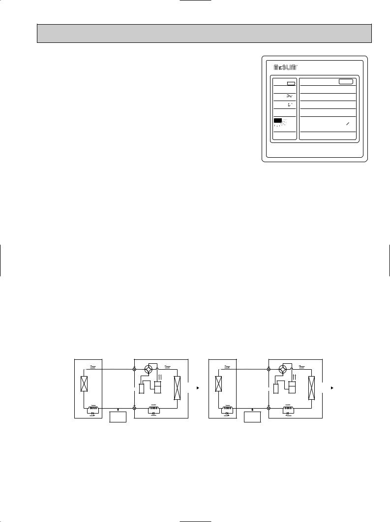
1)Ultra-Thin Remote Controller
The streamlined, square controller is designed to blend with any kind of interior and the adoption of a sophisticated microprocessor allows you to carry out a wide range of operations easily.
2)Ultra-Thin Remote Controller
Units operation mode, set temperature, room temperature, timer setting, fan speed, louver operation, and air flow direction are displayed on the remote controller with the easily understood visual Liquid Crystal Display (LCD).
3)Convenient 24-Hour ON-OFF Timer
The timer allows Mr.SLIM to be switched on or off automatically at the time is shown on the LCD.
-CENTRALLY CONTROLLEDSTAND BY DEFROST ON
CHECK DRY
HEAT COOL
CHECK
SET TEMP 
 F
F
TIMER OFF  AUTO STOP
  AUTO START
  HR
HR
LOW HIGH


 F
F
AUTO RETURN
CHECK TEST RUN
|
POWER |
ON/OFF |
HEAT |
AUTO |
COOL/DRY |
SET |
WARMER |
COOLER |
TEMPERATURE |
||
TIMER |
MODE |
HOURS |
FAN SPEED LOW/HIOGH |
|
|
AIR |
UP/DOWN |
SWING |
DISCHARGE |
|
STOP |
|
CHECK |
TEST RUN |
 MITSUBISHI ELECTRIC
4)Self-Diagnostic Feature Indicates Instantly
In the rare case when a problem occurs, the unit stops operating and the set temperature indicator changes to the self-diagnostic indicator, indicating the location of the fault.
If the check switch is pressed twice, the unit stops operating and the check mode is initiated. The cause of the most recent problem stored in the memory is displayed on the LCD. This is extremely useful for maintenance purposes.
5)Useful Memory Feature for Storing Instructions
The previous set value is memorized so that constant temperature control can be obtained. This is convenient when, for example, a power failure occurs.
(2)Non-polar Two-Wire Remote Controller Cables
The non-polar, two-wire type remote controller cable is slim, installation is simple and troublefree. Remote controller wire can be extended up to 550 yards.
(3)Automatic Cooling / Heating Changeover Operation
An automatic cooling and heating changeover operation system is provided to ensure easy control and year-round air conditioning.
Once the desired temperature is set, unit operation is switched automatically between cooling and heating, in accordance with the room temperatures as low as 23oF.
6.REDI-CHARGED REFRIGERANT SYSTEM
PRE-CHARGE REFRIGERANT REQUIRED FOR MAXIMUM PIPING LENGTH AT
SHIPMENT. PREVENTING TROUBLES DUE TO SHORTAGE OF REFRIGERANT.
The unique refrigerant circuit and a large accumulator always controls the refrigerant to its optimum condition regardless of the length of 164ft maximum or 25ft minimum. The additional refrigerant charging work at the field which often caused uncertain problems heretofore is completely eliminated. This unique system serves to improve the quality of work and reliability, and also helps to speed up the installation work.
Indoor unit |
Outdoor unit |
Indoor unit |
Outdoor unit |
|
4•way |
|
|
4•way |
|
|
|
valve |
|
|
valve |
|
|
Indoor |
|
|
Indoor |
|
|
|
heat |
|
Outdoor |
heat |
|
Outdoor |
|
exchanger |
|
exchanger |
|
|||
Accumulator |
heat |
Accumulator |
heat |
|||
|
|
|||||
|
|
exchanger |
|
|
exchanger |
|
Capillary |
|
Compressor |
Capillary |
|
Compressor |
|
|
Capillary tubes |
|
|
|||
tubes for |
|
tubes for |
|
Capillary tubes |
||
cooling |
Liquid section |
for heating |
heating |
Liquid section |
for cooling |
|
|
of piping |
|
|
of piping |
|
Restrictor |
HIgh-pressure |
Restrictor valve |
Restrictor |
Low-pressure |
Restrictor valve |
|
valve |
liquid |
valve |
two-phase |
|||
|
|
|||||
|
retrigerant |
|
|
retrigerant |
|
With normal circulation systems, a high-pressure refrigerant, condensed for cooling by the outdoor heat exacanger, is reduced in pressure by capillary tubes in the indoor unit after passing through the restrictor valve in the outdoor unit (see Figure 1). With the new circulation system, the direction of the restrictor valve is reversed as shown in Figure 2, and the condensed high pressure refrigerant is reduced in pressure by the capacity tubes in the outdoor unit. This results in a “twophase refrigerant” of reduced pressure in the liquid section of the piping, The density of this two-phase refrigerant is 1/3~ 1/2 of that of the high pressure liquid refrigerant, and thus is required in smaller amounts (see Figures 1 and 2). As a result, the length of the piping can be extended further, and the effects of height differences are reduced. These new circulation system are also equipped with a large accumulator which allows the refrigerant required for the 100ft piping length to be enclosed in the outdoor unit. The result is an air conditioner that requires no charging unless piping is extended beyond 100ft.
3
7. HIGH RELIABILITY AND EASY SERVICING
In addition to the self-diagnostic function, units are also equipped with a 3-minute time delay mechanism (cooling), an auto restart function, an emergency operation function, a test run switch, etc., to assure high reliability and easy servicing.
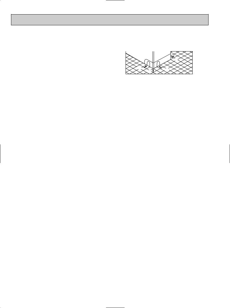
8. FOUR-WAY PIPING ACCESS MAKES INSTALLATION LAYOUT EASY
Piping on the outdoor unit may be connected from either of four directions: front, rear, side or beneath the base.
This easy-access design makes it possible to install a number of units in a compact arrangement at a single site. The outdoor unit allows for unheard-of flexibility in detemining a piping layout, thus greatly simplifying installation.
Red
Front
Right
Base
9. FRONT-ACCESS FACILITATES MAINTENANCE
The outdoor unit has been designed with a frontaccess service panel that allows easy access to all maintenance point, regardless of the installation layout. What’s more, this front panel may be removed by loosening only two screws. It all adds up to greatly simplified maintenance work.
10. NITROGEN GAS IS CHARGED TO INDOOR UNIT
Indoor unit and refrigerant pipes are charged with nitrogen gas (N2) instead of R-22 before shipment from the factory.
4
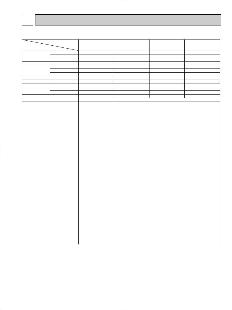
2 |
SPECIFICATIONS |
|
|
|
|||
MODELS : PKH18/24/30/36FK |
|
|
|
||||
|
|
|
Model |
PKH18FK |
PKH24FK |
PKH30FK |
PKH36FK |
Item |
|
|
|
||||
|
|
|
|
|
|
|
|
|
Cooling |
*1 |
Btu/h |
18,000 |
24,000 |
30,000 |
34,200 |
Capacity |
Heating |
*1 |
Btu/h |
18,600[24,100/25,100] |
25,000[30,500/31,500] |
33,000[39,100/40,500] |
38,000[44,100/45,500] |
|
Heating |
*2 |
Btu/h |
10,700[16,200/17,200] |
14,700[20,200/21,200] |
19,000[25,100/26,500] |
19,600[25,700/27,100] |
Moisture removal |
|
Pints/h |
5.3 |
7.0 |
9.1 |
10.5 |
|
Power |
Cooling |
*1 |
kW |
1.79 |
2.36 |
3.12 |
3.44 |
Consomption |
Heating |
*1 |
kW |
1.56[3.16/3.46] |
2.37[3.97/4.27] |
3.02[4.82/5.22] |
3.54[5.34/5.74] |
|
Heating |
*2 |
kW |
1.34[2.94/3.24] |
1.92[3.52/3.82] |
2.48[4.28/4.68] |
2.65[4.45/4.85] |
EER |
|
*1 |
|
10.1 |
10.2 |
9.6 |
9.9 |
SEER |
|
|
|
11.1 |
10.2 |
10.6 |
10.5 |
HSPF |
|
|
|
7.2 |
6.8 |
7.1 |
6.9 |
COP |
|
*1 |
|
3.5 |
3.1 |
3.2 |
3.1 |
|
|
*2 |
|
2.3 |
2.2 |
2.2 |
2.2 |
INDOOR UNIT MODELS |
|
|
PKH18FK |
PKH24FK |
PKH30FK |
PKH36FK |
|
External finish |
|
|
|
|
Munsell 3.4Y 7.7/0.8 |
|
|
Power supply |
|
V,phase,Hz |
|
208/230,1,60 |
|
|
|
Max.fuse size (time dalay) |
|
A |
15 |
|
|
15 |
|
15 |
|
|
||||
Min.ampacity |
|
|
|
|
A |
12 |
|
|
12 |
|
13 |
|
13 |
|
Fan motor |
|
|
|
|
F.L.A. |
0.5 |
|
|
0.5 |
|
0.6 |
|
0.6 |
|
Booster heater |
|
|
|
|
A(kW) |
7.6/8.4[1.6/1.9] |
|
7.6/8.4[1.6/1.9] |
|
8.7/9.6[1.8/2.2] |
|
8.7/9.6[1.8/2.2] |
||
Airflow Hi-Lo |
|
Dry |
|
CFM |
710-530 |
|
|
710-530 |
|
990-780 |
|
990-780 |
||
|
|
|
Wet |
|
CFM |
640-480 |
|
|
640-480 |
|
890-700 |
|
890-700 |
|
Sound level Hi-Lo |
|
|
|
dB(A) |
43-35 |
|
|
43-35 |
|
46-41 |
|
46-41 |
||
Cond. drain connection OD |
|
|
1 |
|
|
1 |
|
1 |
|
1 |
||||
|
|
|
W |
|
in. |
|
|
55-1/8 |
|
|
66-5/32 |
|||
Dimensions |
|
D |
|
in. |
|
|
9-1/4 |
|
|
|
||||
|
|
|
H |
|
in. |
|
|
13-3/8 |
|
|
|
|||
Weight |
|
|
|
|
in. |
57 |
|
|
57 |
|
66 |
|
66 |
|
OUTDOOR UNIT MODELS |
|
lb |
PUH18EK |
|
PUH24EK |
|
PHU30EK |
|
PUH36EK |
|||||
External finish |
|
|
|
|
|
|
|
|
Munsell 5Y 7/1 |
|
|
|
||
Power supply |
|
|
|
|
|
|
|
208/230,1,60 |
|
|
|
|
||
Max.fuse size (time dalay) |
V,phase,Hz |
20 |
|
|
20 |
|
30 |
|
30 |
|||||
Min.ampacity |
|
|
|
|
A |
16 |
|
|
16 |
|
20 |
|
22 |
|
Fan motor |
|
|
|
|
A |
0.75 |
|
|
0.65+0.65 |
|
0.75+0.75 |
|
0.75+0.75 |
|
|
|
|
Model (type) |
F.L.A. |
RH247NAB |
|
NH33NBD |
|
NH41NAD |
|
NH47ND |
|||
Compressor |
|
|
|
|
|
12 |
|
|
11.5 |
|
14.0 |
|
17.5 |
|
|
|
|
|
|
|
R.L.A. |
37 |
|
|
54 |
|
73 |
|
87 |
Crankcase heater |
|
|
|
L.R.A. |
0.11/0.12[23/28] |
|
0.16/0.17[33/39] |
|
0.16/0.17[33/39] |
|
0.16/0.17[33/39] |
|||
Refrigerant control |
|
|
|
A(W) |
|
|
|
Capillary tube |
|
|
|
|||
Defrost method |
|
|
|
|
|
|
|
|
Reverse cycle |
|
|
|
||
Sound level |
|
|
|
|
dB(A) |
53 |
|
|
55 |
|
55 |
|
|
|
|
|
|
W |
|
|
|
|
34-1/4 |
|
38-3/16 |
38-3/16 |
|||
Dimensions |
|
D |
|
in. |
|
|
11-5/8 |
|
13-9/16 |
13-9/16 |
||||
|
|
|
H |
|
in. |
33-1/2 |
|
|
49-9/16 |
|
49-9/16 |
|
49-9/16 |
|
Weight |
|
|
|
|
in. |
131 |
|
|
202 |
|
245 |
|
246 |
|
REMOTE CONTROLLER |
|
lb |
|
|
|
With indoor unit |
|
|
|
|||||
Control voltage (by built-in transformer) |
Indoor unit-remote controller:DC12V. Indoor unit-outdoor unit:DC12V |
|
|
|||||||||||
REFRIGERANT PIPING |
|
|
|
|
|
Not supplied(optional parts) |
|
|
|
|||||
Pipe size |
|
Liquid |
|
|
|
|
3/8 |
|
1/2 |
|
1/2 |
|||
|
|
|
Gas |
|
in. |
|
|
5/8 |
|
3/4 |
|
3/4 |
||
Connection |
|
Indoors |
|
in. |
|
|
|
Flared |
|
|
|
|||
method |
|
Outdoors |
|
|
|
|
|
Flared |
|
|
|
|||
Between the indoor |
Height difference ft |
130 |
|
|
164 |
|
|
164 |
||||||
& outdoor units |
|
Piping length |
ft |
130 |
|
|
164 |
|
|
164 |
||||
NOTES : *1.Rating conditions (cooling)-indoor : 80˚FDB,67˚FWB outdoor : 95˚FDB,7 5˚FWB. |
|
|
|
|||||||||||
|
|
|
(heating)-indoor : 70˚FDB,60˚FWB outdoor : 47˚FDB,43˚FWB. |
|
|
|
||||||||
*2.Rating conditions (heating)-indoor : 70˚FDB,60˚FWB outdoor : 17˚FDB,15˚FWB. |
|
|
|
|||||||||||
*3.Heating capacity and power consumption in [ ] includes heater operation at 208/230V. |
|
|
|
|||||||||||
Operating range |
|
|
|
|
|
|
|
|
|
|
|
|
|
|
|
|
|
|
|
|
|
|
|
|
|
|
|||
|
|
|
|
|
Indoor intake air temperature |
|
Outdoor intake air temperature |
|
|
|
|
|||
|
|
|
|
|
|
|
|
|
|
|
|
|
||
Cooling |
|
Maximum |
|
|
95˚FDB,71˚FWB |
|
|
115˚FDB |
|
|
|
|
||
|
Minimum |
|
|
67˚FDB,57˚FWB |
|
|
0˚FDB |
|
|
|
|
|||
|
|
|
|
|
|
|
|
|
|
|||||
Heating |
|
Maximum |
|
|
80˚FDB,67˚FWB |
|
|
75˚FDB,65˚FWB |
|
|
|
|
||
|
Minimum |
|
|
70˚FDB,68˚FWB |
|
|
17˚FDB,15˚FWB |
|
|
|
|
|||
|
|
|
|
|
|
|
|
|
|
|||||
5

3 
 DATA
DATA
MODELS : PKH18/24/30/36FK 1. PERFORMANS DATA
1) COOLING CAPACITY
|
|
|
Models |
|
|
|
|
|
|
Outdoor intake air DB temperature(˚F) |
|
|
|
|
|
|||||
|
|
|
|
|
|
|
|
|
|
|
|
|
|
|
|
|
|
|
|
|
Models |
|
|
Airflow |
IWB |
|
75 |
|
|
85 |
|
|
95 |
|
|
105 |
|
|
115 |
|
|
|
|
|
(CFM) |
|
|
|
|
|
|
|
|
|
|
|
|
|
|
|
|
|
|
|
|
B.F |
(˚F) |
TC |
SHC |
TPC |
TC |
SHC |
TPC |
TC |
SHC |
TPC |
TC |
SHC |
TPC |
TC |
SHC |
TPC |
|
|
|
|
|
|||||||||||||||||
|
|
|
|
|
|
|
|
|
|
|
|
|
|
|
|
|
|
|
|
|
|
|
|
|
|
71 |
21.0 |
14.4 |
1.56 |
20.2 |
13.9 |
1.69 |
19.4 |
13.3 |
1.84 |
18.5 |
12.7 |
1.99 |
17.6 |
12.1 |
2.15 |
|
|
|
710 |
|
|
|
|
|
|
|
|
|
|
|
|
|
|
|
|
|
PKH18FK |
|
|
67 |
19.5 |
16.0 |
1.52 |
18.8 |
15.4 |
1.65 |
18.0 |
14.8 |
1.79 |
17.1 |
14.0 |
1.93 |
16.3 |
13.4 |
2.07 |
||
|
0.16 |
|
||||||||||||||||||
|
|
|
|
|
|
|
|
|
|
|
|
|
|
|
|
|
|
|
||
|
|
63 |
18.2 |
17.4 |
1.49 |
17.5 |
16.7 |
1.61 |
16.8 |
16.0 |
1.74 |
15.9 |
15.2 |
1.88 |
15.1 |
14.4 |
2.01 |
|||
|
|
|
|
|
||||||||||||||||
|
|
|
|
|
|
|
|
|
|
|
|
|
|
|
|
|
|
|
|
|
|
|
DB 75°F (50%RH) |
62.5 |
18.1 |
15.5 |
1.49 |
17.4 |
14.9 |
1.61 |
16.6 |
14.3 |
1.74 |
15.8 |
13.6 |
1.87 |
15.0 |
12.9 |
2.00 |
||
|
|
|
|
|
|
|
|
|
|
|
|
|
|
|
|
|
|
|
|
|
|
|
DB 72°F (50%RH) |
60 |
17.2 |
15.1 |
1.47 |
16.6 |
14.5 |
1.58 |
15.8 |
13.8 |
1.70 |
15.0 |
13.1 |
1.84 |
14.2 |
12.4 |
1.96 |
||
|
|
|
|
|
|
|
|
|
|
|
|
|
|
|
|
|
|
|
|
|
|
|
DB 70°F (50%RH) |
59 |
16.8 |
14.5 |
1.46 |
16.2 |
14.0 |
1.57 |
15.5 |
13.4 |
1.69 |
14.6 |
12.6 |
1.83 |
13.9 |
12.0 |
1.94 |
||
|
|
|
|
|
|
|
|
|
|
|
|
|
|
|
|
|
|
|
|
|
|
|
|
|
|
71 |
27.9 |
16.1 |
2.05 |
26.9 |
15.5 |
2.23 |
25.8 |
14.9 |
2.43 |
24.6 |
14.2 |
2.63 |
23.4 |
13.5 |
2.84 |
PKH24FK |
|
|
710 |
|
|
|
|
|
|
|
|
|
|
|
|
|
|
|
|
|
|
|
67 |
26.1 |
18.5 |
2.01 |
25.1 |
17.8 |
2.18 |
24.0 |
17.0 |
2.36 |
22.9 |
16.3 |
2.55 |
21.7 |
15.4 |
2.73 |
|||
|
0.16 |
|
||||||||||||||||||
|
|
|
|
|
|
|
|
|
|
|
|
|
|
|
|
|
|
|
||
|
|
63 |
24.3 |
20.5 |
1.97 |
23.4 |
19.7 |
2.12 |
22.4 |
18.9 |
2.30 |
21.3 |
18.0 |
2.47 |
20.1 |
17.0 |
2.65 |
|||
|
|
|
|
|
||||||||||||||||
|
|
|
|
|
|
|
|
|
|
|
|
|
|
|
|
|
|
|
|
|
|
|
DB 75°F (50%RH) |
62.5 |
24.1 |
18.0 |
1.96 |
23.2 |
17.4 |
2.12 |
22.2 |
16.6 |
2.29 |
21.1 |
15.8 |
2.47 |
19.9 |
14.9 |
2.64 |
||
|
|
|
|
|
|
|
|
|
|
|
|
|
|
|
|
|
|
|
|
|
|
|
DB 72°F (50%RH) |
60 |
23.0 |
17.6 |
1.94 |
22.1 |
16.9 |
2.09 |
21.1 |
16.2 |
2.25 |
20.1 |
15.4 |
2.41 |
18.9 |
14.5 |
2.58 |
||
|
|
|
|
|
|
|
|
|
|
|
|
|
|
|
|
|
|
|
|
|
|
|
DB 70°F (50%RH) |
59 |
22.5 |
17.0 |
1.93 |
21.7 |
16.4 |
2.07 |
20.7 |
15.6 |
2.24 |
19.7 |
14.9 |
2.39 |
18.5 |
14.0 |
2.56 |
||
|
|
|
|
|
|
|
|
|
|
|
|
|
|
|
|
|
|
|
|
|
|
|
|
|
|
71 |
34.9 |
21.5 |
2.72 |
33.7 |
20.8 |
2.95 |
32.3 |
19.9 |
3.21 |
30.8 |
19.0 |
3.48 |
29.3 |
18.1 |
3.75 |
PKH30FK |
|
|
990 |
|
|
|
|
|
|
|
|
|
|
|
|
|
|
|
|
|
|
|
67 |
32.6 |
24.5 |
2.66 |
31.4 |
23.6 |
2.88 |
30.0 |
22.5 |
3.12 |
28.6 |
21.5 |
3.37 |
27.1 |
20.3 |
3.61 |
|||
|
0.15 |
|
||||||||||||||||||
|
|
|
|
|
|
|
|
|
|
|
|
|
|
|
|
|
|
|
||
|
|
63 |
30.4 |
26.9 |
2.60 |
29.2 |
25.8 |
2.81 |
27.9 |
24.6 |
3.04 |
26.6 |
23.5 |
3.27 |
25.1 |
22.2 |
3.50 |
|||
|
|
|
|
|
||||||||||||||||
|
|
|
|
|
|
|
|
|
|
|
|
|
|
|
|
|
|
|
|
|
|
|
DB 75°F (50%RH) |
62.5 |
30.2 |
23.8 |
2.59 |
29.0 |
22.9 |
2.80 |
27.7 |
21.9 |
3.03 |
26.3 |
20.7 |
3.26 |
24.9 |
19.6 |
3.49 |
||
|
|
|
|
|
|
|
|
|
|
|
|
|
|
|
|
|
|
|
|
|
|
|
DB 72°F (50%RH) |
60 |
28.8 |
23.2 |
2.57 |
27.6 |
22.2 |
2.77 |
26.3 |
21.2 |
2.99 |
24.9 |
20.1 |
3.21 |
23.5 |
18.9 |
3.43 |
||
|
|
|
|
|
|
|
|
|
|
|
|
|
|
|
|
|
|
|
|
|
|
|
DB 70°F (50%RH) |
59 |
28.2 |
22.4 |
2.56 |
27.0 |
21.5 |
2.76 |
25.7 |
20.4 |
2.98 |
24.4 |
19.4 |
3.19 |
22.9 |
18.2 |
3.41 |
||
|
|
|
|
|
|
|
|
|
|
|
|
|
|
|
|
|
|
|
|
|
|
|
|
|
|
71 |
39.8 |
23.0 |
3.00 |
38.4 |
22.1 |
3.25 |
36.8 |
21.2 |
3.54 |
35.1 |
20.2 |
3.83 |
33.4 |
19.3 |
4.13 |
PKH36FK |
|
|
990 |
|
|
|
|
|
|
|
|
|
|
|
|
|
|
|
|
|
|
|
67 |
37.1 |
26.3 |
2.93 |
35.7 |
25.3 |
3.17 |
34.2 |
24.3 |
3.44 |
32.6 |
23.1 |
3.71 |
30.9 |
21.9 |
3.98 |
|||
|
0.14 |
|
||||||||||||||||||
|
|
|
|
|
|
|
|
|
|
|
|
|
|
|
|
|
|
|
||
|
|
63 |
34.7 |
29.3 |
2.87 |
33.3 |
28.1 |
3.10 |
31.9 |
26.9 |
3.35 |
30.3 |
25.6 |
3.61 |
28.7 |
24.2 |
3.86 |
|||
|
|
|
|
|
||||||||||||||||
|
|
|
|
|
|
|
|
|
|
|
|
|
|
|
|
|
|
|
|
|
|
|
DB 75°F (50%RH) |
62.5 |
34.4 |
25.8 |
2.86 |
33.1 |
24.8 |
3.09 |
31.6 |
23.7 |
3.34 |
30.0 |
22.5 |
3.59 |
28.4 |
21.3 |
3.85 |
||
|
|
|
|
|
|
|
|
|
|
|
|
|
|
|
|
|
|
|
|
|
|
|
DB 72°F (50%RH) |
60 |
32.8 |
25.1 |
2.82 |
31.5 |
24.1 |
3.04 |
30.1 |
23.0 |
3.28 |
28.5 |
21.8 |
3.52 |
26.9 |
20.6 |
3.76 |
||
|
|
|
|
|
|
|
|
|
|
|
|
|
|
|
|
|
|
|
|
|
|
|
DB 70°F (50%RH) |
59 |
32.2 |
24.3 |
2.81 |
30.8 |
23.2 |
3.03 |
29.5 |
22.3 |
3.26 |
27.9 |
21.0 |
3.50 |
26.4 |
19.9 |
3.73 |
||
|
|
|
|
|
|
|
|
|
|
|
|
|
|
|
|
|
|
|
|
|
Notes 1. B.F. : Bypass Factor, IWB : Intake air wet-bulb temperature
TC : Total Capacity (x103 Btu/h), SHC : Sensible Heat Capacity (x103 Btu/h)
TPC : Total Power Consumption (kW)
2.SHC is based on 80˚FDB of indoor intake air temperature.
3.Cooling capacity correction factors and Refrigerant piping length (one way) range.
|
|
|
|
Refrigerant piping length (one way) |
|
|
|
|
|
|
|||||
MODEL |
|
|
|
|
|
|
|
|
|
|
|
|
|
|
|
|
25ft |
40ft |
55ft |
|
70ft |
85ft |
100ft |
115ft |
130ft |
150ft |
164ft |
||||
|
|
|
|
|
|
|
|
|
|
|
|
|
|
|
|
PKH18FK |
1.0 |
0.992 |
0.983 |
|
0.978 |
0.966 |
0.959 |
0.950 |
0.945 |
|
|
|
|
|
|
|
|
|
|
|
|
|
|||||||||
|
|
|
|
|
|
|
|
|
|
|
|
|
|
|
|
PKH24FK |
1.0 |
0.981 |
0.968 |
|
0.952 |
0.940 |
0.925 |
0.913 |
0.900 |
0.886 |
0.874 |
||||
|
|
|
|
|
|
|
|
|
|
|
|
|
|
|
|
PKH30FK |
1.0 |
0.981 |
0.968 |
|
0.952 |
0.940 |
0.925 |
0.913 |
0.900 |
0.886 |
0.874 |
||||
|
|
|
|
|
|
|
|
|
|
|
|
|
|
|
|
PKH36FK |
1.0 |
0.981 |
0.968 |
|
0.952 |
0.940 |
0.925 |
0.913 |
0.900 |
0.886 |
0.874 |
||||
|
|
|
|
|
|
|
|
|
|
|
|
|
|
|
|
6

2) HEATING CAPACITY
|
Models |
|
|
|
|
|
|
|
|
|
Outdoor intake air WB temperature(˚F) |
|
|
|
Auxiliary heater |
|||||||||
Models |
|
|
|
|
|
|
|
|
|
|
|
|
|
|
|
|
|
|
|
|
|
|
208V |
|
Airflow |
IWB |
|
15 |
|
|
25 |
35 |
|
45 |
|
|
55 |
65 |
|
|
230V |
||||||||
|
|
|
|
|
|
|
|
|
|
|
|
|
|
|
|
|
|
|
|
|
|
|
||
|
(CFM) |
(˚F) |
|
CA |
|
PC |
CA |
|
PC |
CA |
|
PC |
CA |
|
PC |
CA |
|
PC |
CA |
|
PC |
CA |
|
PC |
|
|
|
|
|
|
|
|
|
|
|
||||||||||||||
|
|
|
|
|
|
|
|
|
|
|
|
|
|
|
|
|
|
|
|
|
|
|
|
|
|
|
75 |
|
12.1 |
|
1.20 |
14.1 |
|
1.34 |
16.3 |
|
1.49 |
18.7 |
|
1.65 |
21.4 |
|
1.83 |
23.7 |
|
1.99 |
5.5 |
|
1.6 |
PKH18FK |
710 |
|
|
|
|
|
|
|
|
|
|
|
|
|
|
|
|
|
|
|
|
|
|
|
70 |
|
12.4 |
|
1.16 |
14.4 |
|
1.29 |
16.7 |
|
1.44 |
19.1 |
|
1.59 |
21.8 |
|
1.76 |
24.1 |
|
1.91 |
|
|
|
||
|
|
|
|
|
|
|
|
|
|
|
|
|
|
|
|
|
|
|
|
|
|
|
|
|
|
|
65 |
|
12.7 |
|
1.11 |
14.7 |
|
1.24 |
17.0 |
|
1.38 |
19.5 |
|
1.53 |
22.2 |
|
1.69 |
24.5 |
|
1.83 |
6.5 |
|
1.9 |
|
|
|
|
|
|
|
|
|
|
|
|
|
|
|
|
|
|
|
|
|
|
|
|
|
|
|
75 |
|
16.3 |
|
1.82 |
18.9 |
|
2.03 |
21.9 |
|
2.27 |
25.2 |
|
2.51 |
28.8 |
|
2.77 |
32.8 |
|
3.01 |
5.5 |
|
1.6 |
PKH24FK |
710 |
|
|
|
|
|
|
|
|
|
|
|
|
|
|
|
|
|
|
|
|
|
|
|
70 |
|
16.6 |
|
1.76 |
19.4 |
|
1.96 |
22.4 |
|
2.19 |
25.7 |
|
2.42 |
29.3 |
|
2.67 |
33.3 |
|
2.90 |
|
|
|
||
|
|
|
|
|
|
|
|
|
|
|
|
|
|
|
|
|
|
|
|
|
|
|
|
|
|
|
65 |
|
17.0 |
|
1.69 |
19.8 |
|
1.89 |
22.9 |
|
2.10 |
26.2 |
|
2.32 |
29.9 |
|
2.56 |
33.9 |
|
2.78 |
6.5 |
|
1.9 |
|
|
|
|
|
|
|
|
|
|
|
|
|
|
|
|
|
|
|
|
|
|
|
|
|
|
|
75 |
|
21.5 |
|
2.32 |
25.0 |
|
2.59 |
28.9 |
|
2.89 |
33.2 |
|
3.20 |
38.0 |
|
3.53 |
43.2 |
|
3.86 |
6.1 |
|
1.8 |
PKH30FK |
990 |
|
|
|
|
|
|
|
|
|
|
|
|
|
|
|
|
|
|
|
|
|
|
|
70 |
|
21.9 |
|
2.24 |
25.5 |
|
2.50 |
29.6 |
|
2.78 |
33.9 |
|
3.08 |
38.6 |
|
3.40 |
43.7 |
|
3.72 |
7.5 |
|
2.2 |
||
|
|
|
|
|
|
|
|
|
|
|
|
|
|
|
|
|
|
|
|
|
|
|
||
|
|
65 |
|
22.5 |
|
2.15 |
26.1 |
|
2.40 |
30.2 |
|
2.68 |
34.6 |
|
2.96 |
39.4 |
|
3.26 |
44.6 |
|
3.56 |
|||
|
|
|
|
|
|
|
|
|
|
|
|
|||||||||||||
|
|
|
|
|
|
|
|
|
|
|
|
|
|
|
|
|
|
|
|
|
|
|
|
|
|
|
75 |
|
24.7 |
|
2.71 |
28.7 |
|
3.04 |
33.3 |
|
3.39 |
38.2 |
|
3.75 |
43.7 |
|
4.14 |
49.6 |
|
4.49 |
6.1 |
|
1.8 |
PKH36FK |
990 |
|
|
|
|
|
|
|
|
|
|
|
|
|
|
|
|
|
|
|
|
|
|
|
70 |
|
25.3 |
|
2.62 |
29.4 |
|
2.93 |
34.1 |
|
3.26 |
39.0 |
|
3.61 |
44.5 |
|
3.98 |
50.4 |
|
4.28 |
7.5 |
|
2.2 |
||
|
|
|
|
|
|
|
|
|
|
|
|
|
|
|
|
|
|
|
|
|
|
|
||
|
|
65 |
|
25.9 |
|
2.53 |
30.1 |
|
2.82 |
34.8 |
|
3.14 |
39.9 |
|
3.47 |
45.4 |
|
3.83 |
51.3 |
|
4.14 |
|||
|
|
|
|
|
|
|
|
|
|
|
|
|||||||||||||
|
|
|
|
|
|
|
|
|
|
|
|
|
|
|
|
|
|
|
|
|
|
|
|
|
Notes 1. IDB : Intake air dry-bulb |
temperature |
|
|
|
|
|
|
|
|
|
|
|
|
|
|
|
|
|
|
|
||||
CA : Capacity (x103 Btu/h), PC : Power Consumption (kW) |
|
|
|
|
|
|
|
|
|
|
|
|
|
|
|
|||||||||
2.When booster heater is "on", total capacity and total power consnmption should be added the figures described in booster heater colnmn.
•Booster heater ON : When the set temperature is higher than the room temperature by more than 5.4 deg. •Booster heater OFF : When the set temperature is higher than the room temperature by less than 3.6 deg.
3.Heating capacity correction factors.
|
|
Refrigerant piping length (one way) |
|
||
Models |
|
|
|
|
|
|
Less than 100ft |
|
100~130ft |
|
130~164ft |
|
|
|
|
|
|
PKH18FK |
1.00 |
|
0.995 |
|
0.990 |
|
|
|
|
|
|
PKH24FK |
1.00 |
|
0.995 |
|
0.990 |
|
|
|
|
|
|
PKH30FK |
1.00 |
|
0.995 |
|
0.990 |
|
|
|
|
|
|
PKH36FK |
1.00 |
|
0.995 |
|
0.990 |
|
|
|
|
|
|
7
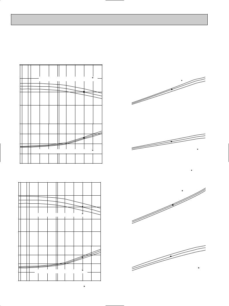
2. PERFORMANCE CURVE
NOTES : A point on the curve shows the reference point.
PKH18FK COOLING CAPACITY
PKH18FK COOLING CAPACITY
|
30 |
|
|
|
|
|
|
|
SHF=0.82 |
||
|
|
|
|
|
|
|
|
|
|
||
3 Btu/h) |
24 |
|
Indoor intake air WB temperature ( F) |
|
|||||||
(x10 |
|
|
|||||||||
|
|
|
|
|
|
|
|
|
|
||
capacity |
18 |
|
|
|
|
|
|
|
|
71 |
|
|
|
|
|
|
|
|
|
|
|||
|
|
|
|
|
|
|
|
|
67 |
||
Total |
|
|
|
|
|
|
|
|
|
||
|
|
|
|
|
|
|
|
|
63 |
||
12 |
|
|
|
|
|
|
|
|
|
||
|
|
|
|
|
|
|
|
|
|
||
(kW) |
2.5 |
|
|
|
|
|
|
|
|
|
|
|
|
|
|
|
|
|
|
|
71 |
||
consumption |
|
|
|
|
|
|
|
|
|
||
2.0 |
|
|
|
|
|
|
|
|
67 |
||
|
|
|
|
|
|
|
|
63 |
|||
|
|
|
|
|
|
|
|
|
|||
1.5 |
|
|
|
|
|
|
|
|
|
||
|
|
|
|
|
|
|
|
|
|
||
Total power |
1.0 |
|
Indoor intake air WB temperature ( F) |
|
|||||||
|
|
|
|
|
|
|
|
|
|||
023 |
32 35 |
45 |
55 |
65(67) |
75 |
85 |
95 |
105 |
115 |
||
|
|||||||||||
Outdoor intake air DB temperature ( F)
F)
PKH24FK COOLING CAPACITY
|
36 |
|
|
|
|
|
|
SHF=0.71V |
|||
3 Btu/h) |
|
|
|
|
|
|
|
|
|
||
30 |
|
|
|
|
|
|
|
|
|
||
(x10 |
|
|
|
|
|
|
|
|
|
||
|
|
|
|
|
|
|
|
|
|
||
capacity |
24 |
|
|
|
|
|
|
|
|
71 |
|
|
|
|
|
|
|
|
|
|
|||
|
|
Indoor intake air WB temperature ( F) |
|
67 |
|||||||
Total |
|
|
|
63 |
|||||||
18 |
|
|
|
|
|
|
|
|
|
||
|
12 |
|
|
|
|
|
|
|
|
|
|
(kW) |
3.0 |
|
|
|
|
|
|
|
|
71 |
|
consumption |
|
|
|
|
|
|
|
|
|||
|
|
|
|
|
|
|
|
|
|||
|
|
|
|
|
|
|
|
|
67 |
||
2.5 |
|
|
|
|
|
|
|
|
63 |
||
|
|
|
|
|
|
|
|
|
|||
2.0 |
|
|
|
|
|
|
|
|
|
||
Total power |
1.5 |
|
Indoor intake air WB temperature ( F) |
|
|
||||||
023 |
32 35 |
45 |
55 |
65(67) |
75 |
85 |
95 |
105 |
115 |
||
|
|||||||||||
|
|
|
Outdoor intake air DB temperature ( F) |
|
|
||||||
PKH18FK HEATING CAPACITY
Does not include booster heater (1.9kW)
3 Btu/h) |
30 |
|
|
|
|
|
|
|
|
|
|
|
|
|
|
65 |
|
|
|
|
|
|
|
|
|
|
|
|
|
|
|||
|
|
|
|
|
|
|
|
|
|
|
|
|
|
|
||
(x10 |
24 |
|
|
|
|
|
|
|
|
|
|
|
|
|
|
|
|
|
|
|
|
|
|
|
|
|
|
|
|
|
70 |
||
|
|
|
|
|
|
|
|
|
|
|
|
|
|
|||
|
|
|
Indoor intake air DB temperature ( F) |
|
|
|
|
|
||||||||
|
|
|
|
|
|
|
|
75 |
||||||||
capacityTotal |
18 |
|
|
|
|
|
|
|
|
|
|
|
|
|
|
|
|
|
|
|
|
|
|
|
|
|
|
|
|
|
|
||
|
|
|
|
|
|
|
|
|
|
|
|
|
|
|
|
|
(kW) |
12 |
|
|
|
|
|
|
|
|
|
|
|
|
|
|
|
|
|
|
|
|
|
|
|
|
|
|
|
|
|
|
||
2.5 |
|
|
|
|
|
|
|
|
|
|
|
|
|
|
|
|
consumption |
|
|
|
|
|
|
|
|
|
|
|
|
|
|
75 |
|
2.0 |
|
|
|
|
|
|
|
|
|
|
|
|
|
|
||
|
|
|
|
|
|
|
|
|
|
|
|
|
|
|
||
|
|
|
|
|
|
|
|
|
|
|
|
|
|
|
|
70 |
|
1.5 |
|
|
|
|
|
|
|
|
|
|
|
|
|
|
65 |
powerTotal |
|
|
|
|
|
|
|
|
|
|
|
|
|
|
|
|
|
|
|
|
|
|
|
|
|
|
|
|
|
|
|
||
|
|
|
|
|
|
|
|
|
|
|
|
|
|
|
|
|
1.0 |
|
|
|
|
|
Indoor intake air DB temperature ( F) |
|
|
|
|||||||
|
|
|
|
|
|
|
|
|
||||||||
|
|
|
|
|
|
|
|
|
|
|
|
|
|
|
|
|
|
|
|
|
|
|
|
|
|
|
|
|
|
|
|
|
|
|
|
|
|
|
|
|
|
|
|
|
|
|
|
|
|
|
|
15 |
25 |
35 |
45 |
|
55 |
|
65 |
||||||||
|
|
|
|
Outdoor intake air WB temperature ( F) |
|
|
||||||||||
|
|
PKH24FK HEATING CAPACITY |
|
|
|
|
|
|||||||||
|
35 |
|
|
|
|
Does not include booster heater (1.9kW) |
||||||||||
Btu/h) |
|
|
|
|
|
|
|
|
|
|
|
|
|
|
65 |
|
|
|
|
|
|
|
|
|
|
|
|
|
|
|
|
||
|
|
|
|
|
|
|
|
|
|
|
|
|
|
|
70 |
|
|
|
|
Indoor |
intake air DB temperature ( F) |
|
|
|
|
75 |
|||||||
3 |
30 |
|
|
|
|
|
|
|
|
|
|
|
|
|
|
|
(x10 |
|
|
|
|
|
|
|
|
|
|
|
|
|
|
|
|
|
|
|
|
|
|
|
|
|
|
|
|
|
|
|
||
|
|
|
|
|
|
|
|
|
|
|
|
|
|
|
|
|
capacityTotal |
24 |
|
|
|
|
|
|
|
|
|
|
|
|
|
|
|
|
|
|
|
|
|
|
|
|
|
|
|
|
|
|
|
|
|
18 |
|
|
|
|
|
|
|
|
|
|
|
|
|
|
|
|
|
|
|
|
|
|
|
|
|
|
|
|
|
|
|
|
(kW) |
12 |
|
|
|
|
|
|
|
|
|
|
|
|
|
|
|
|
|
|
|
|
|
|
|
|
|
|
|
|
|
|
||
3.0 |
|
|
|
|
|
|
|
|
|
|
|
|
|
|
75 |
|
consumption |
|
|
|
|
|
|
|
|
|
|
|
|
|
|
|
70 |
2.5 |
|
|
|
|
|
|
|
|
|
|
|
|
|
|
65 |
|
|
|
|
|
|
|
|
|
|
|
|
|
|
|
|
||
|
|
|
|
|
|
|
|
|
|
|
|
|
|
|
|
|
|
|
|
|
|
|
|
|
|
|
|
|
|
|
|
|
|
power |
2.0 |
|
|
|
|
|
|
|
|
|
|
|
|
|
|
|
|
|
|
|
|
|
|
|
|
|
|
|
|
|
|
||
1.5 |
|
|
|
|
|
|
|
|
|
|
|
|
|
|
|
|
|
|
|
|
|
Indoor intake air DB temperature ( F) |
|
|
|||||||||
|
|
|
|
|
|
|
|
|
||||||||
Total |
|
|
|
|
|
|
|
|
|
|
|
|
|
|
|
|
|
|
|
|
|
|
|
|
|
|
|
|
|
|
|
|
|
15 |
25 |
35 |
45 |
|
55 |
|
65 |
|||||||||
|
|
|
||||||||||||||
Outdoor intake air WB temperature ( F)
F)
8

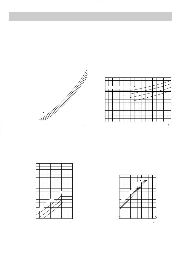
NOTES : A point on the curve shows the reference point.
PKH30FK COOLING CAPACITY |
PKH30FK HEATING CAPACITY |
Total power consumption(kW) Total capacity(x10 3Btu/h)
42 |
SHF=0.75 |
|
|
36 |
Btu/h) |
|
|
|
3 |
24 |
63 |
capacity(x10 |
30 |
71 |
|
|
67 |
|
|
indoor intake air WB temperature(°F) |
Total |
|
|
|
4.0 |
71 |
consumption(kW) |
|
||
3.5 |
67 |
|
63 |
|
|
3.0 |
|
|
2.5 |
|
power |
2.0 |
|
|
|
indoor intake air WB temperature(°F) |
Total |
|
|
0 23 32 35 |
45 |
55 |
65 (67) 75 |
85 |
95 |
105 |
115 |
Outdoor intake air DB temperature(°F)
Does not include booster heater(2.2kW)
48 |
indoor intake air DB temperature(°F) |
65 |
|||
|
|||||
42 |
|
|
|
|
70 |
|
|
|
|
75 |
|
36 |
|
|
|
|
|
30 |
|
|
|
|
|
24 |
|
|
|
|
|
18 |
|
|
|
|
|
4.0 |
|
|
|
|
75 |
|
|
|
|
|
|
|
|
|
|
|
70 |
3.5 |
|
|
|
|
65 |
3.0 |
|
|
|
|
|
2.5 |
|
|
|
|
|
2.0 |
|
|
|
|
|
|
indoor intake air DB temperature(°F) |
|
|||
1.5 |
25 |
35 |
45 |
55 |
65 |
15 |
|||||
Outdoor intake air WB temperature(°F)
PKH36FK COOLING CAPACITY |
PKH36FK HEATING CAPACITY |
|
42 |
|
|
|
|
SHF=0.71 |
|
54 |
Does not include booster heater(2.2kW) |
||||||
Btu/h) |
|
|
|
|
|
|
|
|
indoor intake air DB temperature(°F) |
65 |
|||||
|
|
|
|
|
|
|
|
Btu/h) |
|
||||||
36 |
|
|
|
|
|
|
|
48 |
|
|
|
|
75 |
||
3 |
|
|
|
|
|
|
|
|
|
|
|
|
|
70 |
|
capacity(x10Total |
|
|
|
|
|
|
|
|
capacity(x10Total |
|
|
|
|
|
|
|
|
|
|
|
|
|
|
71 |
3 |
32 |
|
|
|
|
|
|
|
|
|
|
|
|
|
|
|
|
|
|
|
||
|
30 |
|
|
|
|
|
|
67 |
|
|
|
|
|
|
|
|
|
|
|
|
|
|
|
|
|
|
|
|
|
||
|
|
|
|
|
|
|
63 |
|
|
|
|
|
|
|
|
|
|
|
|
|
|
|
|
|
36 |
|
|
|
|
|
|
|
|
|
|
|
|
|
|
|
|
|
|
|
|
|
|
|
24 |
|
|
|
|
|
|
|
|
30 |
|
|
|
|
|
|
indoor intake air WB temperature(°F) |
|
|
|
|
|
|
|
|
||||||
|
|
|
|
|
|
|
|
|
|
||||||
|
|
|
|
|
|
|
|
|
|
24 |
|
|
|
|
|
consumption(kW) |
4.5 |
|
|
|
|
|
|
|
consumption(kW) |
4.5 |
|
|
|
|
75 |
|
|
|
|
|
|
|
71 |
|
|
|
|
|
70 |
||
|
|
|
|
|
|
|
|
|
|
|
|
|
|
65 |
|
|
4.0 |
|
|
|
|
|
|
67 |
|
4.0 |
|
|
|
|
|
|
|
|
|
|
|
|
63 |
|
|
|
|
|
|
||
|
|
|
|
|
|
|
|
|
|
|
|
|
|
|
|
|
3.5 |
|
|
|
|
|
|
|
|
3.5 |
|
|
|
|
|
power |
3.0 |
|
|
|
|
|
|
|
power |
3.0 |
|
|
|
|
|
2.5 |
|
|
|
|
|
|
|
2.5 |
|
|
|
|
|
||
Total |
indoor intake air WB temperature(°F) |
|
|
Total |
|
indoor intake air DB temperature(°F) |
|
||||||||
|
|
|
|
|
|
||||||||||
|
0 23 32 35 |
45 |
55 |
65 (67) 75 |
85 |
95 |
105 |
115 |
|
2.015 |
25 |
35 |
45 |
55 |
65 |
|
Outdoor intake air DB temperature(°F) |
|
|
|
|
Outdoor intake air WB temperature(°F) |
|
||||||||
9
3. CONDENSING PRESSURE AND SUCTION PRESSURE
Data is based on the condition of indoor humidity 50%. Air flow should be set at HI.
A point on the curve shows the reference point.
<Cooling mode>
|
|
|
|
|
|
|
|
|
|
PKH18FK |
|
|
|
|
|
|
|
|
|
|
||||
(psi.G) 350 |
|
|
|
|
|
|
|
|
|
|
|
|
|
|
|
|
|
|
|
|
|
86 |
|
|
|
|
|
|
|
|
|
|
|
|
|
|
|
|
|
|
|
|
|
|
|
|
|||
|
340 |
|
|
|
|
|
|
|
|
|
|
|
|
|
|
|
|
|
|
|
|
|
|
|
|
|
|
|
|
|
|
|
|
|
|
|
|
|
|
|
|
|
|
|
|
|
|
||
|
330 |
|
|
|
|
|
|
|
|
|
|
|
|
|
|
|
|
|
|
|
|
|
80 |
|
|
|
|
|
|
|
|
|
|
|
|
|
|
|
|
|
|
|
|
|
|
|
|
||
|
320 |
|
|
|
|
|
|
|
|
|
|
|
|
|
|
|
|
|
|
|
|
|
75 |
|
|
|
|
|
|
|
|
|
|
|
|
|
|
|
|
|
|
|
|
|
|
|
|
||
|
310 |
|
|
|
|
|
|
|
|
|
|
|
|
|
|
|
|
|
|
|
|
|
70 (psi.G) 100 |
|
|
|
|
|
|
|
|
|
|
|
|
|
|
|
|
|
|
|
|
|
|
|
|||
|
300 |
|
|
|
|
|
|
|
|
|
|
|
|
|
|
|
|
|
|
|
|
|
|
90 |
|
|
|
|
|
|
|
|
|
|
|
|
|
|
|
|
|
|
|
|
|
|
|
||
pressureCondensing |
290 |
|
|
|
|
|
|
|
|
|
|
|
|
|
|
|
|
|
|
|
|
|
pressureSuction |
|
|
|
|
|
|
|
|
|
|
|
|
|
|
|
|
|
|
|
|
|
|
||||
280 |
|
|
|
|
|
|
|
|
|
|
|
|
|
|
|
|
|
|
|
|
|
80 |
||
|
|
|
|
|
|
|
|
|
|
|
|
|
|
|
|
|
|
|
|
|
|
|
||
|
270 |
|
|
|
|
|
|
|
|
|
|
|
|
|
|
|
|
|
|
|
|
|
|
|
|
|
|
|
|
|
|
|
|
|
|
|
|
|
|
|
|
|
|
|
|
|
|
||
|
260 |
|
|
|
|
|
|
|
|
|
|
|
|
|
|
|
|
|
|
|
|
|
|
70 |
|
|
|
|
|
|
|
|
|
|
|
|
|
|
|
|
|
|
|
|
|
|
|
||
|
250 |
|
|
|
|
|
|
|
|
|
|
|
|
|
|
|
|
|
|
|
|
|
|
|
|
|
|
|
|
|
|
|
|
|
|
|
|
|
|
|
|
|
|
|
|
|
|
||
|
240 |
|
|
|
|
|
|
|
|
|
|
|
|
|
|
|
|
|
|
|
|
|
|
60 |
|
|
|
|
|
|
|
|
|
|
|
|
|
|
|
|
|
|
|
|
|
|
|
||
|
230 |
|
|
|
|
|
|
|
|
|
|
|
|
|
|
|
|
|
|
|
|
|
|
|
|
|
|
|
|
|
|
|
|
|
|
|
|
|
|
|
|
|
|
|
|
|
|
||
|
220 |
|
|
|
|
|
|
|
|
|
|
|
|
|
|
|
|
|
|
|
|
|
|
50 |
|
|
|
|
|
|
|
|
|
|
|
|
|
|
|
|
|
|
|
|
|
|
|
||
|
210 |
|
|
|
|
|
|
|
|
|
|
|
|
|
|
|
|
|
|
|
|
|
|
|
|
|
|
|
|
|
|
|
|
|
|
|
|
|
|
|
|
|
|
|
|
|
|
||
|
200 |
|
|
|
|
|
|
|
|
|
|
|
|
|
|
|
|
|
|
|
|
|
|
40 |
|
190 |
|
|
|
|
|
Indoor DB |
|
|
|
|
|
|
|
|
|
|
|
|
|||||
|
|
|
|
|
|
|
|
|
|
|
|
|
|
|
|
|
|
|||||||
|
180 |
|
|
temperature( F) |
|
|
|
|
|
|
|
|
|
|
|
|
30 |
|||||||
|
|
|
|
|
|
|
|
|
|
|
|
|
|
|
||||||||||
|
170 |
|
|
|
|
|
|
|
|
|
|
|
|
|
|
|
|
|
|
|
|
|
|
|
|
|
|
|
|
|
|
|
|
|
|
|
|
|
|
|
|
|
|
|
|
|
|
||
|
160 |
|
|
|
|
|
|
|
|
|
|
|
|
|
|
|
|
|
|
|
|
|
|
20 |
|
|
|
|
|
|
|
|
|
|
|
|
|
|
|
|
|
|
|
|
|
|
|
||
|
150 |
|
|
|
|
|
|
|
|
|
|
|
|
|
|
|
|
|
|
|
|
|
|
|
|
|
|
40 |
50 |
60 |
70 |
80 |
90 |
100 |
110 |
|
|||||||||||||
|
30 |
|
|
|||||||||||||||||||||
|
|
|
|
|
|
|
|
Outdoor ambient temperature |
|
|
DB( F) |
|
||||||||||||
PKH18FK
86
80
Indoor DB temperature( F) |
75 |
70
30 |
40 |
50 |
60 |
70 |
80 |
90 |
100 |
110 |
|
|
Outdoor ambient temperature |
|
DB( F) |
||||
Data is based on the condition of outdoor humidity 75%. A point on the curve shows the reference point.
<Heating mode> |
|
|
|
|
|
|
|
|
PKH18FK |
|
|
||
(psi.G) |
350 |
|
|
|
|
|
|
340 |
|
|
|
|
|
|
330 |
|
|
|
|
|
|
320 |
|
|
|
|
|
|
310 |
|
|
|
|
|
|
300 |
|
|
|
|
|
pressure |
290 |
|
|
|
|
|
280 |
|
|
|
|
|
|
270 |
|
|
|
|
|
|
260 |
|
|
|
|
|
|
Condensing |
250 |
|
|
|
|
|
240 |
|
|
temperature( |
F) |
|
|
230 |
|
|
|
75 |
||
220 |
|
|
|
|||
|
|
|
70 |
|||
210 |
|
|
|
65 |
||
|
200 |
|
DB |
|
|
|
|
190 |
Indoor |
|
|
|
|
|
|
|
|
|
||
|
180 |
|
|
|
|
|
|
170 |
|
|
|
|
|
|
|
|
|
|
|
|
|
160 |
|
|
|
|
|
|
150 |
|
|
|
|
|
|
20 25 30 35 40 45 50 55 60 65 70 |
|||||
|
|
|
|
|
DB( F) |
|
|
|
Outdoor ambient temperature |
|
|||
|
|
PKH18FK |
|
|
||
(psi.G) |
80 |
|
|
|
|
|
|
|
|
|
|
75 |
|
|
|
|
|
|
F) |
|
|
70 |
|
|
temperature( |
70 |
|
|
|
|
|
65 |
||
|
|
|
|
|
||
pressure |
60 |
|
|
|
|
|
50 |
|
DB |
|
|
||
|
|
|
|
|||
|
Indoor |
|
|
|
||
|
|
|
|
|
||
Suction |
40 |
|
|
|
|
|
|
|
|
|
|
||
30 |
|
|
|
|
|
|
|
|
|
|
|
|
|
|
20 |
|
|
|
|
|
|
10 |
|
|
|
|
|
|
20 25 30 35 40 45 50 55 60 65 70 |
|||||
|
|
|
|
|
|
DB( F) |
Outdoor ambient temperature
10
Data is based on the condition of indoor humidity 50%. Air flow should be set at HI.
A point on the curve shows the reference point.
<Cooling mode>
|
|
|
|
|
|
|
|
|
|
PKH24FK |
|
|
|
|
|
|
|
|
|
|
|
|
|
|
|
|
|
PKH24FK |
|
|
|
|
|||||||||
|
360 |
|
|
|
|
|
|
|
|
|
|
|
|
|
|
|
|
|
|
|
|
|
|
|
|
|
|
|
|
|
|
|
|
|
|
|
|
|
|
|
|
|
|
|
|
|
|
|
|
|
|
|
|
|
|
|
|
|
|
|
|
|
|
|
|
|
|
|
|
|
|
|
|
|
|
|
|
|
|
|
|
|
|
(psi.G) 350 |
|
|
|
|
|
|
|
|
|
|
|
|
|
|
|
|
|
|
|
|
|
|
|
|
|
|
|
|
|
|
|
|
|
|
|
|
|
|
|
|
|
|
|
|
|
|
|
|
|
|
|
|
|
|
|
|
|
|
|
|
|
|
|
|
|
|
|
|
|
|
|
|
|
|
|
|
|
|
|
|
|
||
|
340 |
|
|
|
|
|
|
|
|
|
|
|
|
|
|
|
|
|
|
|
|
|
|
|
|
|
|
|
|
|
|
|
|
|
|
|
|
|
|
|
|
|
|
|
|
|
|
|
|
|
|
|
|
|
|
|
|
|
|
|
|
|
|
|
|
|
|
|
|
|
|
|
|
|
|
|
|
|
|
|
|
|
|
|
330 |
|
|
|
|
|
|
|
|
|
|
|
|
|
|
|
|
|
|
|
|
|
|
|
|
|
|
|
|
|
|
|
|
|
|
|
|
|
|
|
|
|
|
|
|
|
|
|
|
|
|
|
|
|
|
|
|
|
|
|
|
|
|
|
|
|
|
|
|
|
|
|
|
|
|
|
|
|
|
|
|
|
|
|
320 |
|
|
|
|
|
|
|
|
|
|
|
|
|
|
|
|
|
|
|
|
|
86 |
|
|
|
|
|
|
|
|
|
|
|
|
|
|
|
|
|
|
|
|
|
|
|
|
|
|
|
|
|
|
|
|
|
|
|
|
|
|
|
|
|
|
|
|
|
|
|
|
|
|
|
|
|
|
|
|
|
|
||
|
310 |
|
|
|
|
|
|
|
|
|
|
|
|
|
|
|
|
|
|
|
|
|
80 (psi.G) 100 |
|
|
|
|
|
|
|
|
|
|
|
|
|
|
|
|
||
|
|
|
|
|
|
|
|
|
|
|
|
|
|
|
|
|
|
|
|
|
|
|
|
|
|
|
|
|
|
|
|
|
|
|
|
|
|
||||
|
300 |
|
|
|
|
|
|
|
|
|
|
|
|
|
|
|
|
|
|
|
|
|
75 |
|
|
|
|
|
|
|
|
|
|
|
|
|
|
|
|
|
|
|
|
|
|
|
|
|
|
|
|
|
|
|
|
|
|
|
|
|
|
|
|
|
|
|
|
|
|
|
|
|
|
|
|
|
|
|
|
|
|
||
pressureCondensing |
290 |
|
|
|
|
|
|
|
|
|
|
|
|
|
|
|
|
|
|
|
|
|
70 |
pressureSuction |
90 |
|
|
|
|
|
|
|
|
|
|
|
|
|
|
|
|
|
|
|
|
|
|
|
|
|
|
|
|
|
|
|
|
|
|
|
|
|
|
|
|
|
|
|
|
|
|
|
|
|
|
|
|
|
|||||
280 |
|
|
|
|
|
|
|
|
|
|
|
|
|
|
|
|
|
|
|
|
|
|
80 |
|
|
|
|
|
|
|
|
|
|
|
|
|
|
|
|
||
|
|
|
|
|
|
|
|
|
|
|
|
|
|
|
|
|
|
|
|
|
|
|
|
|
|
|
|
|
|
|
|
|
|
|
|
|
|
|
|
||
|
270 |
|
|
|
|
|
|
|
|
|
|
|
|
|
|
|
|
|
|
|
|
|
|
|
|
Indoor DB temperature( F) |
|
|
|
|
|
|
|||||||||
|
|
|
|
|
|
|
|
|
|
|
|
|
|
|
|
|
|
|
|
|
|
|
|
|
|
|
|
|
|||||||||||||
|
260 |
|
|
|
|
|
|
|
|
|
|
|
|
|
|
|
|
|
|
|
|
|
|
|
70 |
|
|
|
|
|
|
|
|
|
|
|
|
|
|
|
|
|
250 |
|
|
|
|
|
|
|
|
|
|
|
|
|
|
|
|
|
|
|
|
|
|
|
|
|
|
|
|
|
|
|
|
|
|
|
|
|
|
|
|
|
|
|
|
|
|
|
|
|
|
|
|
|
|
|
|
|
|
|
|
|
|
|
|
|
|
|
|
|
|
|
|
|
|
|
|
|
|
|
|
||
|
240 |
|
|
|
|
|
|
|
|
|
|
|
|
|
|
|
|
|
|
|
|
|
|
|
60 |
|
|
|
|
|
|
|
|
|
|
|
|
|
|
|
|
|
|
|
|
|
|
|
|
|
|
|
|
|
|
|
|
|
|
|
|
|
|
|
|
|
|
|
|
|
|
|
|
|
|
|
|
|
|
|
|
||
|
230 |
|
|
|
|
|
|
|
|
|
|
|
|
|
|
|
|
|
|
|
|
|
|
|
|
|
|
|
|
|
|
|
|
|
|
|
|
|
|
|
|
|
|
|
|
|
|
|
|
|
|
|
|
|
|
|
|
|
|
|
|
|
|
|
|
|
|
|
|
|
|
|
|
|
|
|
|
|
|
|
|
||
|
220 |
|
|
|
|
|
|
|
|
|
|
|
|
|
|
|
|
|
|
|
|
|
|
|
50 |
|
|
|
|
|
|
|
|
|
|
|
|
|
|
|
|
|
|
|
|
|
|
|
|
|
|
|
|
|
|
|
|
|
|
|
|
|
|
|
|
|
|
|
|
|
|
|
|
|
|
|
|
|
|
|
|
||
|
210 |
|
|
|
|
|
|
|
|
|
|
|
|
|
|
|
|
|
|
|
|
|
|
|
|
|
|
|
|
|
|
|
|
|
|
|
|
|
|
|
|
|
200 |
|
|
|
|
|
Indoor DB |
|
|
|
|
|
|
|
|
|
|
|
|
|
40 |
|
|
|
|
|
|
|
|
|
|
|
|
|
|
|
|
||||
|
|
|
|
|
|
|
|
|
|
|
|
|
|
|
|
|
|
|
|
|
|
|
|
|
|
|
|
|
|
|
|
|
|
|
|||||||
|
190 |
|
|
temperature( F) |
|
|
|
|
|
|
|
|
|
|
|
|
|
|
|
|
|
|
|
|
|
|
|
|
|
|
|
|
|
||||||||
|
|
|
|
|
|
|
|
|
|
|
|
|
|
|
|
|
|
|
|
|
|
|
|
|
|
|
|
|
|
|
|
||||||||||
|
180 |
|
|
|
|
|
|
|
|
|
|
|
|
|
|
|
|
|
|
|
|
|
|
|
30 |
|
|
|
|
|
|
|
|
|
|
|
|
|
|
|
|
|
|
|
|
|
|
|
|
|
|
|
|
|
|
|
|
|
|
|
|
|
|
|
|
|
|
|
|
|
|
|
|
|
|
|
|
|
|
|
|
||
|
170 |
|
|
|
|
|
|
|
|
|
|
|
|
|
|
|
|
|
|
|
|
|
|
|
|
|
|
|
|
|
|
|
|
|
|
|
|
|
|
|
|
|
|
|
|
|
|
|
|
|
|
|
|
|
|
|
|
|
|
|
|
|
|
|
|
|
|
|
|
|
|
|
|
|
|
|
|
|
|
|
|
||
|
160 |
|
|
|
|
|
|
|
|
|
|
|
|
|
|
|
|
|
|
|
|
|
|
|
20 |
|
|
|
|
|
|
|
|
|
|
|
|
|
|
|
|
|
|
|
|
|
|
|
|
|
|
|
|
|
|
|
|
|
|
|
|
|
|
|
|
|
|
|
|
|
|
|
|
|
|
|
|
|
|
|
|
||
|
|
|
|
|
|
|
|
|
|
|
|
|
|
|
|
|
|
|
|
|
|
|
|
|
|
|
|
|
|
|
|
|
|
|
|
|
|
|
|
|
|
|
30 |
40 |
50 |
60 |
70 |
80 |
90 |
100 |
110 |
|
|
30 |
40 |
50 |
60 |
70 |
80 |
90 |
|||||||||||||||||||||||
|
|
|
|
||||||||||||||||||||||||||||||||||||||
|
|
|
|
|
|
|
|
Outdoor ambient temperature |
|
|
DB( F) |
|
|
|
|
|
|
|
Outdoor ambient temperature |
||||||||||||||||||||||
86
80
75
70
100 110 DB( F)
F)
Data is based on the condition of outdoor humidity 75%. A point on the curve shows the reference point.
<Heating mode> |
|
|
|
|
|
|
|
|
PKH24FK |
|
|
||
(psi.G) |
350 |
|
|
|
|
|
|
340 |
|
|
|
|
|
|
330 |
|
|
|
|
|
|
320 |
|
|
|
|
|
|
310 |
|
|
|
|
|
|
300 |
|
|
|
|
|
pressure |
290 |
|
|
|
F) |
|
280 |
|
|
temperature( |
|
||
|
|
|
|
|||
270 |
|
|
|
75 |
||
260 |
|
|
|
|||
Condensing |
250 |
|
DB |
|
70 |
|
240 |
Indoor |
|
|
65 |
||
230 |
|
|
|
|
||
220 |
|
|
|
|
||
210 |
|
|
|
|
|
|
200 |
|
|
|
|
|
|
|
|
|
|
|
|
|
|
190 |
|
|
|
|
|
|
180 |
|
|
|
|
|
|
170 |
|
|
|
|
|
|
160 |
|
|
|
|
|
|
150 |
|
|
|
|
|
|
20 25 30 35 40 45 50 55 60 65 70 |
|||||
|
|
|
|
|
DB( F) |
|
|
|
Outdoor ambient temperature |
|
|||
|
|
PKH24FK |
|
|
||
(psi.G) |
80 |
|
|
|
F) |
75 |
|
|
|
|
|
||
|
70 |
|
|
temperature( |
70 |
|
|
|
|
|
|||
|
|
|
|
65 |
||
|
|
|
|
|
||
pressure |
60 |
|
|
|
|
|
50 |
|
DB |
|
|
||
|
|
|
|
|||
|
Indoor |
|
|
|
||
40 |
|
|
|
|
||
Suction |
|
|
|
|
||
|
|
|
|
|
||
30 |
|
|
|
|
|
|
20 |
|
|
|
|
|
|
|
|
|
|
|
|
|
|
10 |
|
|
|
|
|
|
20 25 30 35 40 45 50 55 60 65 70 |
|||||
|
|
|
|
|
|
DB( F) |
Outdoor ambient temperature
11
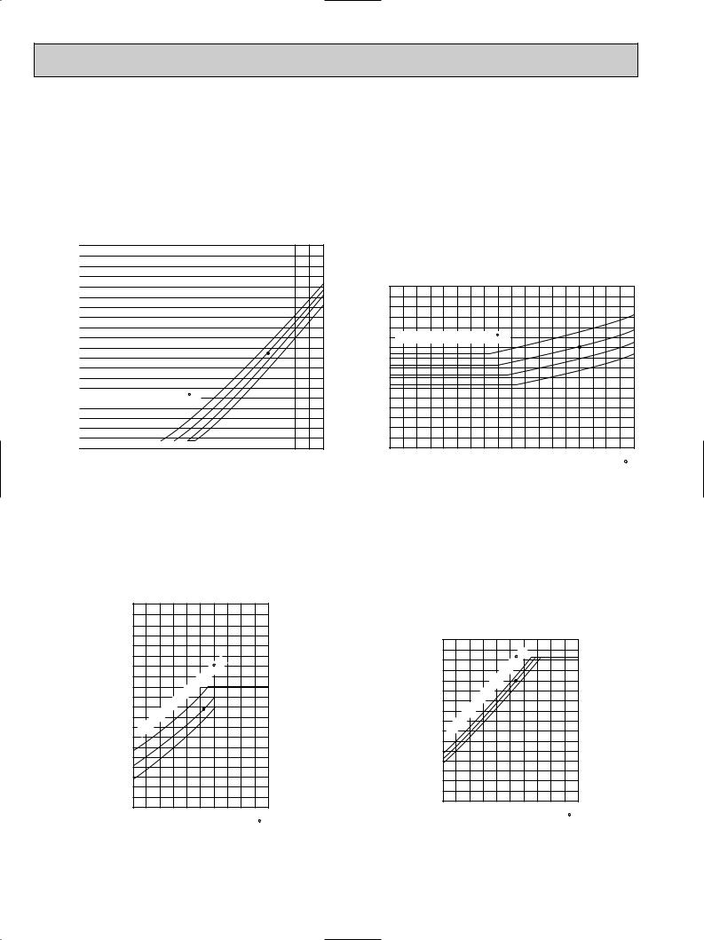
Data is based on the condition of indoor humidity 50%. Air flow should be set at HI.
A point on the curve shows the reference point.
<Cooling mode>
|
|
|
|
|
|
|
|
|
PKH30FK |
|
|
|
|
|
|
|||
(psi.G) |
350 |
|
|
|
|
|
|
|
|
|
|
|
|
|
|
|
|
|
|
|
|
|
|
|
|
|
|
|
|
|
|
|
|
|
|
||
|
340 |
|
|
|
|
|
|
|
|
|
|
|
|
|
|
|
|
|
|
330 |
|
|
|
|
|
|
|
|
|
|
|
|
|
|
|
|
|
|
320 |
|
|
|
|
|
|
|
|
|
|
|
|
|
|
|
|
|
|
310 |
|
|
|
|
|
|
|
|
|
|
|
|
|
|
|
|
|
|
300 |
|
|
|
|
|
|
|
|
|
|
|
|
|
|
|
|
|
pressure |
290 |
|
|
|
|
|
|
|
|
|
|
|
|
|
|
|
|
|
260 |
|
|
|
|
|
|
|
|
|
|
|
|
|
|
|
|
|
|
|
280 |
|
|
|
|
|
|
|
|
|
|
|
|
|
|
|
|
|
|
270 |
|
|
|
|
|
|
|
|
|
|
|
|
|
|
|
|
|
Condensing |
250 |
|
|
|
|
|
|
|
|
|
|
|
|
|
|
|
|
|
240 |
|
|
|
|
|
|
|
|
|
|
|
|
|
|
|
|
|
|
|
|
|
|
|
|
|
|
|
|
|
|
|
|
|
|
|
|
|
|
230 |
|
|
|
|
|
|
|
|
|
|
|
|
|
|
|
|
|
|
220 |
|
|
|
|
|
|
|
|
|
|
|
|
|
|
|
|
|
|
210 |
|
|
|
|
|
|
|
|
|
|
|
|
|
|
|
|
|
|
200 |
|
Indoor DB temperature( F) |
|
|
|
|
|
|
|
||||||||
|
|
|
|
|
|
|
|
|||||||||||
|
190 |
|
|
|
|
|
|
|
|
|
|
|
|
|
|
|
|
|
|
180 |
|
|
|
|
|
|
|
|
|
|
|
|
|
|
|
|
|
|
170 |
|
|
|
|
|
|
|
|
|
|
|
|
|
|
|
|
|
|
160 |
|
|
|
|
|
|
|
|
|
|
|
|
|
|
|
|
|
|
|
|
|
|
|
|
|
|
|
|
|
|
|
|
|
|
|
|
|
150 |
|
|
|
|
|
|
|
|
|
|
|
|
|
|
|
|
|
|
30 |
40 |
50 |
60 |
70 |
80 |
90 |
100 |
||||||||||
|
|
|||||||||||||||||
Outdoor ambient temperature
86
80 (psi.G) 110
75
70 100
pressure |
90 |
|
80 |
||
|
||
Suction |
70 |
|
60 |
||
|
||
|
50 |
|
|
40 |
|
|
30 |
110 DB( F)
F)
PKH30FK
|
86 |
|
Indoor DB temperature( F) |
80 |
|
75 |
||
|
||
|
70 |
30 |
40 |
50 |
60 |
70 |
80 |
90 |
100 |
110 |
|
|
Outdoor ambient temperature |
|
DB( F) |
||||
Data is based on the condition of outdoor humidity 75%. A point on the curve shows the reference point.
<Heating mode> |
|
|
|
|
|
|
|
|
|
PKH30FK |
|
|
|
(psi.G) |
340 |
|
|
|
|
|
|
330 |
|
|
|
|
|
|
320 |
|
|
|
|
|
|
310 |
|
|
|
|
|
|
300 |
|
|
|
|
|
|
290 |
|
|
|
|
|
pressure |
280 |
|
|
temperature( |
F) |
|
270 |
|
|
|
|||
|
|
|
|
|||
260 |
|
|
|
75 |
||
250 |
|
|
|
|||
|
|
|
70 |
|||
Condensing |
240 |
|
DB |
|
65 |
|
230 |
Indoor |
|
|
|
||
220 |
|
|
|
|
||
210 |
|
|
|
|
||
200 |
|
|
|
|
|
|
190 |
|
|
|
|
|
|
|
|
|
|
|
|
|
|
180 |
|
|
|
|
|
|
170 |
|
|
|
|
|
|
160 |
|
|
|
|
|
|
150 |
|
|
|
|
|
|
140 |
|
|
|
|
|
|
20 25 30 35 40 45 50 55 60 65 70 |
|||||
|
|
|
|
|
DB( F) |
|
|
|
Outdoor ambient temperature |
|
|||
|
|
PKH30FK |
|
|
||
(psi.G) |
80 |
|
|
|
|
|
|
70 |
|
|
|
F) |
75 |
|
|
|
temperature( |
70 |
||
|
|
|
|
|||
|
|
|
|
|
||
|
60 |
|
|
|
65 |
|
pressure |
|
|
|
|
||
50 |
|
DB |
|
|
||
40 |
Indoor |
|
|
|
||
|
|
|
|
|||
Suction |
|
|
|
|
||
30 |
|
|
|
|
||
|
|
|
|
|
||
20 |
|
|
|
|
|
|
|
|
|
|
|
|
|
|
10 |
|
|
|
|
|
|
20 25 30 35 40 45 50 55 60 65 70 |
|||||
|
|
|
|
|
|
DB( F) |
Outdoor ambient temperature
12
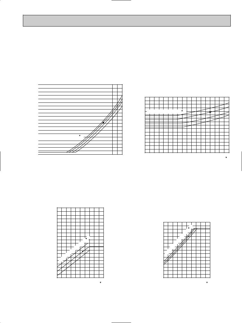
Data is based on the condition of indoor humidity 50%.
Air flow should be set at HI.
A point on the curve shows the reference point.
<Cooling mode>
PKH36FK |
PKH36FK |
(psi.G) |
350 |
|
|
|
|
|
|
|
|
|
|
|
|
|
|
|
|
|
|
|
|
|
|
|
|
|
|
|
|
|
|
|
|
|
|
|
|
||
|
340 |
|
|
|
|
|
|
|
|
|
|
|
|
|
|
|
|
|
|
|
330 |
|
|
|
|
|
|
|
|
|
|
|
|
|
|
|
|
|
|
|
320 |
|
|
|
|
|
|
|
|
|
|
|
|
|
|
|
|
|
|
|
310 |
|
|
|
|
|
|
|
|
|
|
|
|
|
|
|
|
|
|
|
300 |
|
|
|
|
|
|
|
|
|
|
|
|
|
|
|
|
|
|
pressure |
290 |
|
|
|
|
|
|
|
|
|
|
|
|
|
|
|
|
|
|
260 |
|
|
|
|
|
|
|
|
|
|
|
|
|
|
|
|
|
|
|
|
280 |
|
|
|
|
|
|
|
|
|
|
|
|
|
|
|
|
|
|
|
270 |
|
|
|
|
|
|
|
|
|
|
|
|
|
|
|
|
|
|
Condensing |
250 |
|
|
|
|
|
|
|
|
|
|
|
|
|
|
|
|
|
|
240 |
|
|
|
|
|
|
|
|
|
|
|
|
|
|
|
|
|
|
|
|
230 |
|
|
|
|
|
|
|
|
|
|
|
|
|
|
|
|
|
|
|
220 |
|
|
|
|
|
|
|
|
|
|
|
|
|
|
|
|
|
|
|
210 |
|
|
|
|
|
|
|
|
|
|
|
|
|
|
|
|
|
|
|
|
|
Indoor DB temperature( F) |
|
|
|
|
|
|
|
|||||||||
|
200 |
|
|
|
|
|
|
|
|
|
|||||||||
|
|
|
|
|
|
|
|
|
|||||||||||
|
190 |
|
|
|
|
|
|
|
|
|
|
|
|
|
|
|
|
|
|
|
180 |
|
|
|
|
|
|
|
|
|
|
|
|
|
|
|
|
|
|
|
170 |
|
|
|
|
|
|
|
|
|
|
|
|
|
|
|
|
|
|
|
160 |
|
|
|
|
|
|
|
|
|
|
|
|
|
|
|
|
|
|
|
150 |
|
|
|
|
|
|
|
|
|
|
|
|
|
|
|
|
|
|
|
|
|
40 |
50 |
60 |
70 |
|
80 |
90 |
100 |
|||||||||
|
30 |
|
|||||||||||||||||
Outdoor ambient temperature
86
80 (psi.G)
75
70
Suction pressure
110 DB( F)
F)
90 |
|
86 |
|
|
|
||
80 |
|
80 |
|
|
75 |
||
|
Indoor DB temperature( F) |
||
70 |
70 |
||
|
60
50
40
30
20
30 |
40 |
50 |
60 |
70 |
80 |
90 |
100 |
110 |
|
|
Outdoor ambient temperature |
|
DB( F) |
||||
Data is based on the condition of outdoor humidity 75%. A point on the curve shows the reference point.
<Heating mode> |
|
|
|
|
|
|
|
|
PKH36FK |
|
|
||
(psi.G) |
390 |
|
|
|
|
|
|
380 |
|
|
|
|
|
|
370 |
|
|
|
|
|
|
360 |
|
|
|
|
|
|
350 |
|
|
|
|
|
|
340 |
|
|
|
|
|
pressure |
330 |
|
|
|
|
|
320 |
|
|
|
|
|
|
310 |
|
|
|
|
|
|
300 |
|
|
temperature( |
F) |
|
|
Condensing |
290 |
|
|
|
75 |
|
280 |
|
|
|
|||
|
|
|
70 |
|||
270 |
|
|
|
65 |
||
260 |
|
DB |
|
|
||
|
|
|
|
|||
250 |
Indoor |
|
|
|
||
|
|
|
|
|||
240 |
|
|
|
|
||
|
|
|
|
|
||
|
230 |
|
|
|
|
|
|
|
|
|
|
|
|
|
220 |
|
|
|
|
|
|
210 |
|
|
|
|
|
|
200 |
|
|
|
|
|
|
190 |
|
|
|
|
|
|
20 25 30 35 40 45 50 55 60 65 70 |
|||||
|
|
|
|
|
DB( F) |
|
|
|
Outdoor ambient temperature |
|
|||
|
|
PKH36FK |
|
|
||
(psi.G) 80 |
|
|
|
|
|
|
|
70 |
|
|
|
F) |
75 |
|
|
|
temperature( |
70 |
||
|
|
|
|
|||
|
|
|
|
|
||
|
60 |
|
|
|
65 |
|
pressure |
|
|
|
|
||
50 |
|
DB |
|
|
||
40 |
Indoor |
|
|
|
||
|
|
|
|
|||
Suction |
|
|
|
|
||
30 |
|
|
|
|
||
|
|
|
|
|
||
20 |
|
|
|
|
|
|
|
|
|
|
|
|
|
|
10 |
|
|
|
|
|
|
20 25 30 35 40 45 50 55 60 65 70 |
|||||
|
|
|
|
|
|
DB( F) |
Outdoor ambient temperature
13
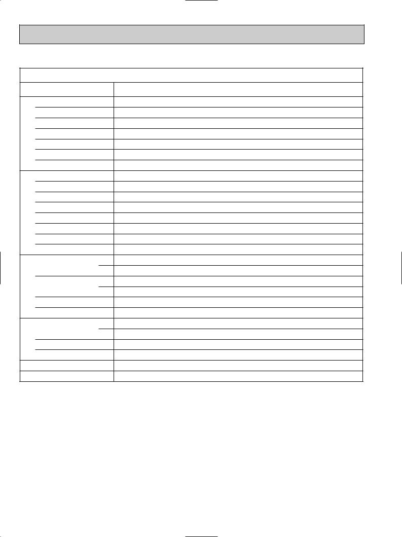
4. STANDARD OPERATION DATA
|
Models |
|
|
|
Item |
|
|
|
Voltage |
|
|
|
|
|
|
circuit |
Frequency |
|
|
Total input |
|
|
|
Electrical |
|
|
|
Indoor fan current |
|
|
|
|
|
|
|
|
Booster heater current |
|
|
|
Outdoor fan current |
|
|
|
Comp. current |
|
|
|
Condensing pressure |
|
|
circuit |
Suction pressure |
|
|
Discharge temperature |
|
|
|
|
|
|
|
Refrigerant |
Condensing temperature |
|
|
Comp.shell bottom temperature |
|||
|
Suction temperature |
|
|
|
Ref. pipe length |
|
|
|
Refrigerant charge |
|
|
|
Intake |
|
DB |
|
|
||
|
|
|
|
|
air temperature |
|
WB |
|
|
|
|
side |
Discharge |
|
DB |
Indoor |
|
|
|
air temperature |
|
WB |
|
|
|
||
|
|
|
|
|
Fan speed |
|
|
|
|
|
|
|
Airflow (High) |
|
|
side |
Intake |
|
DB |
|
|||
|
|
||
air temperature |
|
WB |
|
Outdoor |
|
|
|
Fan speed upper/lower |
|
|
|
|
|
||
|
|
|
|
|
Airflow |
|
|
|
|
|
|
Capacity |
|
|
|
SHF |
|
|
|
|
|
|
|
|
PKH18FK |
|
|
PKH24FK |
|
|
PKH30FK |
|
|
PKH36FK |
||||||||||||||||
Unit |
Cooling |
|
Heating |
Cooling |
|
Heating |
Cooling |
|
Heating |
Cooling |
|
Heating |
||||||||||||||||||
|
|
|
|
|||||||||||||||||||||||||||
|
V |
208/230 |
|
208/230 |
208/230 |
|
208/230 |
208/230 |
|
208/230 |
208/230 |
|
208/230 |
|||||||||||||||||
|
Hz |
|
|
|
|
|
|
|
|
|
|
|
|
|
|
|
|
|
|
|
|
|
|
|
|
|
|
|
|
|
|
|
|
|
60 |
|
|
|
|
|
60 |
|
|
|
|
|
60 |
|
|
|
|
|
60 |
|
|
||||||
kW |
1.79 |
|
|
|
2.36 |
|
2.37 |
3.12 |
|
3.02 |
3.44 |
|
3.54 |
|||||||||||||||||
|
1.56 |
|
|
|
||||||||||||||||||||||||||
|
A |
0.5 |
|
|
0.5 |
|
0.5 |
|
|
0.5 |
|
0.5 |
|
|
0.5 |
|
0.5 |
|
|
0.5 |
|
|||||||||
|
A |
|
|
|
|
7.6/8.4 |
|
|
|
|
7.6/8.4 |
|
|
|
|
7.6/8.4 |
|
|
|
|
8.7/9.6 |
|||||||||
|
|
|
|
|
|
|
|
|
|
|
|
|
|
|
|
|||||||||||||||
|
A |
0.75 |
|
0.75 |
0.65+0.65 |
|
0.65+0.65 |
0.75+0.75 |
|
0.75+0.75 |
0.75+0.75 |
|
0.75+0.75 |
|||||||||||||||||
|
A |
7.4/6.9 |
|
6.1/5.9 |
9.3/8.7 |
|
9.5/8.7 |
12.6/11.8 |
|
12.2/11.4 |
14.3/13.2 |
|
14.7/13.7 |
|||||||||||||||||
psi.G |
255 |
|
202 |
240 |
|
243 |
245 |
|
236 |
243 |
|
263 |
||||||||||||||||||
psi.G |
81 |
|
|
61 |
|
75 |
|
|
63 |
|
80 |
|
|
60 |
|
74 |
|
|
60 |
|
||||||||||
|
˚F |
182 |
|
126 |
158 |
|
149 |
158 |
|
159 |
160 |
|
170 |
|||||||||||||||||
|
˚F |
118 |
|
102 |
115 |
|
115 |
115 |
|
113 |
115 |
|
120 |
|||||||||||||||||
|
˚F |
66 |
|
|
34 |
|
46 |
|
|
35 |
|
49 |
|
|
32 |
|
45 |
|
|
33 |
|
|||||||||
|
˚F |
171 |
|
111 |
141 |
|
126 |
138 |
|
130 |
142 |
|
148 |
|||||||||||||||||
|
ft |
|
|
|
|
|
|
|
|
|
|
|
|
|
|
|
|
|
|
|
|
|
|
|
|
|
|
|
|
|
|
|
|
|
|
|
|
|
|
|
|
25 |
|
|
|
|
|
25 |
|
|
|
|
|
25 |
|
|
|||||
|
|
|
|
|
5 lbs 8 oz |
|
9 lbs 15 oz |
|
10 lbs 2 oz |
|
10 lbs 9 oz |
|||||||||||||||||||
|
˚F |
80 |
|
|
|
|||||||||||||||||||||||||
|
|
|
|
|
80 |
|
|
70 |
|
80 |
|
|
70 |
|
80 |
|
|
70 |
|
|||||||||||
|
|
|
70 |
|
|
|
|
|
|
|
|
|
|
|||||||||||||||||
|
˚F |
67 |
|
|
60 |
|
67 |
|
|
60 |
|
67 |
|
|
60 |
|
67 |
|
|
60 |
|
|||||||||
|
˚F |
61 |
|
|
96 |
|
58 |
|
|
105 |
59 |
|
|
103 |
58 |
|
|
109 |
||||||||||||
|
˚F |
59 |
|
|
68 |
|
56 |
|
|
70 |
|
58 |
|
|
70 |
|
56 |
|
|
71 |
|
|||||||||
r.p.m. |
|
|
|
|
|
|
|
|
|
|
|
|
|
|
|
|
|
|
|
|
|
|
|
|
|
|||||
|
|
|
1,490 |
|
|
1,490 |
|
|
1,490 |
|
|
1,490 |
|
|
||||||||||||||||
CFM |
|
|
|
710 |
|
|
|
|
|
710 |
|
|
|
|
|
990 |
|
|
|
|
|
990 |
|
|
||||||
|
˚F |
95 |
|
|
|
|
95 |
|
|
47 |
|
95 |
|
|
47 |
|
95 |
|
|
47 |
|
|||||||||
|
|
|
47 |
|
|
|
|
|
|
|
|
|
|
|||||||||||||||||
|
˚F |
75 |
|
|
43 |
|
75 |
|
|
43 |
|
75 |
|
|
43 |
|
75 |
|
|
43 |
|
|||||||||
r.p.m. |
|
|
|
|
|
|
|
|
|
|
|
|
|
|
|
|
|
|
|
|
|
|
|
|
|
|||||
|
|
|
790 |
|
|
750/750 |
|
|
760/760 |
|
|
760/760 |
|
|
||||||||||||||||
CFM |
|
|
|
1,590 |
|
|
3,170 |
|
|
3,350 |
|
|
3,350 |
|
|
|||||||||||||||
Btu/h |
18,000 |
|
|
|
24,000 |
|
25,000 |
30,000 |
|
33,000 |
34,100 |
|
38,000 |
|||||||||||||||||
|
18,600 |
|
|
|
||||||||||||||||||||||||||
|
|
|
0.82 |
|
|
|
|
0.71 |
|
|
|
|
0.75 |
|
|
|
|
0.71 |
|
|
|
|
||||||||
|
|
|
|
|
|
|
|
|
|
|
|
|
|
|
|
|
|
|
||||||||||||
|
|
|
|
|
|
|
|
|
|
|
|
|
|
|
|
|
|
|
|
|
|
|
|
|
|
|
|
|
|
|
14
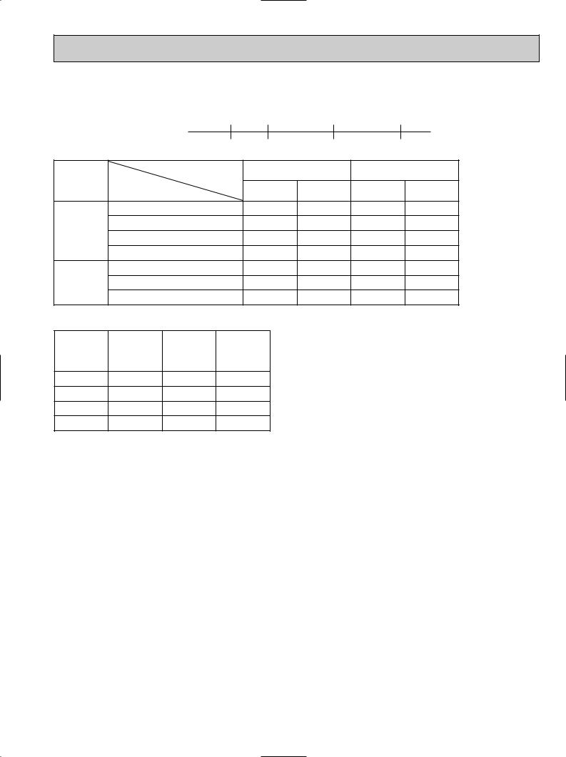
5.OPERATING RANGE
1)POWER SUPPLY
|
Min. |
|
|
Max. |
1 Phase 60Hz 208/230V |
198V |
208V |
230V |
253V |
|
|
|
|
Guaranteed voltage range
2) OPERATION
|
Air intake temperature |
Indoor |
|
|
Outdoor |
|
Function |
|
|
|
|
|
|
|
Condition |
DB(˚F) |
WB(˚F) |
DB(˚F) |
WB(˚F) |
|
|
Standard temperature |
80 |
67 |
95 |
75 |
|
Cooling |
Maximum temperature |
95 |
71 |
115 |
— |
|
MInimum temperature |
67 |
57 |
23 |
— |
||
|
||||||
|
Maximum humidity |
80 |
75 |
80 |
75 |
|
|
Standard temperature |
70 |
60 |
47 |
43 |
|
Heating |
Maximum temperature |
80 |
67 |
75 |
65 |
|
|
MInimum temperature |
70 |
60 |
17 |
15 |
6. OUTLET AIR SPEED AND COVERAGE RANGE
Model |
Airflow |
Air speed |
Coverage |
|
(CFM) |
(ft/sec) |
range(ft) |
||
|
||||
PKH18FK |
710 |
16.1 |
41 |
|
PKH24FK |
710 |
16.1 |
41 |
The air coverage range is the value up to the position where the air speed is 0.8ft/sec. when air is blown out horizontally from the unit at the High notch position.
The coverage range should be used only as a general guideline since it varies according to the size of the room and furniture installed inside the room.
PKH30FK |
990 |
17.7 |
50 |
PKH36FK |
990 |
17.7 |
50 |
7. ADDITIONAL REFRIGERANT CHARGE (R-22(oz))
|
Outdoor unit |
|
|
|
Refrigerant piping length (one way) |
|
|
|
|
|
|
|
|||
Model |
precharged |
|
|
|
|
|
|
|
|
|
|
|
|
|
|
|
|
|
|
|
|
|
|
|
|
|
|
|
|
||
|
(up to 100ft) |
25ft |
40ft |
55ft |
70ft |
85ft |
100ft |
115ft |
130ft |
150ft |
164ft |
||||
|
|
||||||||||||||
|
|
|
|
|
|
|
|
|
|
|
|
|
|
|
|
PKH18FK |
5 lbs 8 oz |
0 |
0 |
0 |
0 |
0 |
0 |
2 |
4 |
|
|
|
|
|
|
|
|
|
|
|
|
||||||||||
|
|
|
|
|
|
|
|
|
|
|
|
|
|
|
|
PKH24FK |
9 lbs 15 oz |
0 |
0 |
0 |
0 |
0 |
0 |
2 |
4 |
7 |
|
9 |
|
||
|
|
|
|
|
|
|
|
|
|
|
|
|
|
|
|
PKH30FK |
10 lbs 2 oz |
0 |
0 |
0 |
0 |
0 |
0 |
5 |
10 |
16 |
|
20 |
|
||
|
|
|
|
|
|
|
|
|
|
|
|
|
|
|
|
PKH36FK |
10 lbs 9 oz |
0 |
0 |
0 |
0 |
0 |
0 |
5 |
10 |
16 |
|
20 |
|
||
|
|
|
|
|
|
|
|
|
|
|
|
|
|
|
|
15
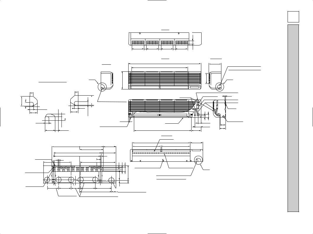
17/3
16 |
|
|
Top |
|
15/32-2 |
|
PKH18/24FK |
UnitIndoor.1.4 |
|
|
|
|
|
|
|
|
|
|
9-1/4 |
9-1/4 |
9-1/4 |
9-1/4 |
1/2 |
|
|
|
|
|
1-25/32 |
1-25/32 1-25/32 |
|
|
|
||
|
|
|
|
|
|
|||
|
|
|
Front |
|
|
|
Right side |
|
|
Left side |
|
55-1/8 |
|
|
|
9-1/4 |
|
|
|
42-15/16 |
Air intake |
|
|
|
Knock out hole for right piping |
|
|
|
|
|
|
Refrigerant pipe. Drain pipe |
|
||
|
|
|
|
|
|
|
|
|
|
-133/8 |
|
|
|
|
7-3/4 |
C |
|
|
A |
|
|
|
|
|
|
|
|
Knock out hole for piping |
|
|
|
|
|
|
|
A |
C |
|
|
|
|
|
|
|
1-3/16 |
|
|
|
|
|
|
|
|
1-3/16 |
|
|
|
|
|
|
|
|
|
|
|
|
|
|
Terminal block for remote controller |
||
|
|
|
|
|
|
|
||
3-15/16 |
1- |
|
5/32 |
1-15/32 B
2-29/32
1-17/32
3-27/32
2-29/32
 9/16-2
15/32-1 2-9/16
1-15/32
|
3-15/16 |
17/32 |
5/32 |
1- |
|
Knock out hole for left piping
Drain hose for 31/32
 left-hand side piping
|
Liquid pipe |
Terminal block for control |
19/32 |
|
|
|
|
|
|
|
Terminal block for power supply |
|
|
|
Gas pipe |
|
|
|
Bolt |
Drain hose |
|
2-5/32 |
Drain hose |
|
|
||
|
|
4-23/32 (Gas pipe) |
4-1/32 |
43-11/16 |
|
7-7/32 (Liquid pipe) |
4-3/8 |
Lower side
Auto vane
|
|
|
Unit center |
|
|
|
|
|
20-9/16 |
|
55-1/8 |
9-7/16 |
|
|
|
|
38-31/32 |
9-21/32 |
|
|
|
|
Air outlet |
20-9/16 |
Air outlet |
||
|
|
|
|
17-29/32 |
|
|
|
|
|
|
|
|
|
|
|
10x3-19/32=(35-13/16) |
11-7/32 |
|
|
|
|
|
|
|
|
||
|
|
|
35-7/16 |
3/4 |
|
|
|
|
|
|
|
|
|
Wall fixture |
23/32 |
23/32 Drainage range |
Drainage range |
3-19/32 |
13/32 |
1-3/16 |
1-5/32 |
|
|
|
|
|
|
|
|
on left-hand side |
on right-hand side |
|
|
|
|
|
|
||||
|
|
|
|
|
|
|
Under panel |
Change vane (manual) |
|||||
66-{1/4 hole for |
|
|
|
|
|
|
|
|
|
||||
|
|
|
|
|
|
|
|
11-1/32 |
Removable at left-hand |
B |
|||
tapping screw |
|
|
|
|
|
|
|
|
|
||||
|
|
|
|
|
|
1-3/16 |
3-5/32 |
side piping |
|
Knock out hole for under-piping |
|||
|
|
|
|
|
|
7-1/4 |
|
||||||
|
|
|
|
|
|
|
|
||||||
|
|
|
|
|
|
|
|
Refrigerant pipe. Drain pipe |
|||||
|
|
|
|
|
|
|
|
|
|
||||
32-{15/32 |
|
|
|
|
|
1-3/18 |
|
|
|
2-3/8 |
|
|
|
hole for bolt |
8-27/32 9-7/16 |
7-3/32 |
11-1/32 |
12-3/8 |
|
|
|
|
|
|
|||
|
|
|
|
|
|
|
|||||||
|
|
Hole for |
|
24 |
7-17/32 |
Rear piping opening |
|
|
|
||||
|
|
tapping screw |
Range for left rear piping opening |
|
|
|
|
|
|
|
|||
Liquid pipe
Gas pipe
mm : Unit
DIMENSIONS AND OUTLINES 4
2

|
|
|
|
|
|
|
Top |
|
|
|
|
Front |
|
|
|
|
|
|
|
-15/32 |
|
|
|
Air |
|
|
|
|
|
|
|
|
|
|
intake |
|
|
|
|
|
2 |
|
|
|
|
|
|
|
|
|
|
|
||
|
|
|
3/16 |
more |
9-1/4 |
9-1/4 |
9-1/4 |
9-1/4 |
1/2 |
|
|
|
|
1- |
or |
9-1/4 |
|
||||
|
|
more |
Air |
|
|
1-25/32 |
1-25/32 |
1-25/32 |
1-25/32 |
|
2 or more |
10 or more |
outlet |
|
|
|
|
|
|
|
|
or |
5-/15/16 or less |
|
|
Front |
|
Knock out hole |
Right side |
|||
|
|
10 |
|
|
|
|
|
for right piping |
|
|
|
|
|
|
|
|
|
|
|
||
|
|
|
|
|
|
|
66-5/32 |
|
|
9-1/4 |
|
|
|
Left side |
|
|
|
53-15/16 Alr Intake |
|
|
|
|
|
|
|
|
|
|
|
|
|
|
Knock out hole for wiring
A C
|
|
1-3/16 |
|
1-3/16 |
|
A |
3/8- |
|
|
|
|
-73/4 |
|
|
|
|
|
|
|
|
|
|
|
|
|||
15/16-3 |
17/32-1 |
|
|
|
|
|
|
|
|
|
|
|
|
B |
|
|
|
15/16-3 |
13 |
|
|
|
|
|
|
||
|
|
|
|
|
|
|
|
|
|
|
|
|
|
|
5/32 |
1-15/32 |
|
1-15/32 |
17/32 |
5/32 |
Knock out hole |
|
Terminal block for remote controller |
|
19/32 |
C |
|
|
|
|
Terminal block for control |
|
|||||||||
|
2-29/32 |
|
2-29/32 |
for left piping |
|
|
or less |
|
|||||
|
|
|
9/16 |
|
1- |
|
|
|
Terminal block for powar supply |
2 |
|
||
|
|
|
2- |
|
|
|
|
|
|
|
|
|
|
|
|
1-17/32 |
15/32 |
|
|
|
|
|
|
|
|
|
|
|
|
|
|
|
|
|
|
|
|
21/32-1 |
9/32-2 |
Bolt |
|
|
|
|
1- |
|
|
|
|
|
|
|
|
||
|
|
3-27/32 |
2-9/16 |
|
|
|
|
|
|
|
|
|
|
|
|
|
|
|
|
|
31/32 |
|
Drain hose |
1 |
2-5/32(Gas pipe) |
4-1/32 |
|
|
|
|
|
|
|
|
|
|
4-3/8 |
||||
|
|
|
|
|
|
|
Drain hose for |
|
|
|
4-23/32(Liquid pipe) |
||
|
|
|
|
|
|
|
43-11/16 (Drain hose) |
|
7-7/32 |
|
|
||
|
|
Drainage range on |
|
|
|
|
left-handside piping |
|
|
|
|||
|
|
|
|
|
|
|
|
|
|
|
|
||
|
|
|
Unit center |
|
|
|
|
|
|
|
|
|
|
|
|
Left hand side |
|
|
|
|
|
Lower side |
|
|
|
||
|
|
|
|
|
|
Drainage range on |
|
|
|
|
|||
|
|
|
|
|
|
|
|
|
|
|
|
||
|
|
|
|
|
|
|
|
55-1/8 |
|
|
9-7/16 |
|
|
|
|
Unit out line |
|
|
|
|
right-hand side |
|
|
|
|
||
|
|
|
|
|
|
27-5/16 Air outlet |
|
27-5/16 Air outlet |
|
|
|
||
|
|
|
|
50 |
|
|
9-21/32 |
|
|
|
|
||
|
|
|
|
|
|
|
|
|
|
|
|
||
|
Wall fixture |
|
|
23-7/16 |
|
|
|
|
|
|
|
|
|
|
13x3-19/32=(7-3/16) |
11-7/32 |
|
|
|
|
|
|
|||
|
|
|
|
|
|
|
|
|
|
|||
84- 1/4 hole |
|
|
|
35-7/16 |
|
3/4 |
|
|
|
|
|
|
23/32 |
23/32 |
|
|
3-19/32 |
|
|
|
|
|
|
|
|
for tapping |
|
|
|
|
13/32 |
3/16-1 |
|
|
|
|
||
screw |
|
|
|
|
|
|
|
|
|
|
||
|
|
|
|
|
|
|
|
|
|
|
|
|
|
|
|
|
|
|
|
|
|
|
|
|
louvers(manual) |
|
|
|
|
|
|
|
1/4 |
3/16 |
5/32 |
5/32-1 |
1/32-11 |
B |
|
|
|
|
|
|
|
Under panel (Removable at |
|||||
|
|
|
|
|
|
|
|
|
|
|
|
left-hand piping) |
|
|
|
|
|
|
|
7- |
1- |
3- |
|
|
|
|
|
|
|
|
|
|
3/16-1 |
|
|
|
|
Auto vanes |
11-5/8 |
|
8-27/32 |
9-7/16 |
7-3/32 |
11-1/32 |
12-3/8 |
|
|
-23/8 |
|
Knock out hole for under-piping |
|
|
|
|
|
|
|
|||||||
|
|
|
|
|
|
Refrigerant pipe .Drain pipe |
||||||
|
|
Range for left |
|
29-17/32 |
|
7-17/32 |
|
|
||||
|
|
|
|
|
|
|
||||||
4115/32 hole |
|
|
|
|
|
|
|
|
|
|
||
|
rear piping hole |
|
|
|
12- |
1/4 hole |
|
|
||||
for bolt |
|
|
|
|
|
|
||||||
|
|
|
|
|
Rear piping hole |
for tapping screw |
|
|||||
|
|
|
|
|
|
|
||||||
Range for left rear piping hole
17
30/36FK PKH
1 |
Liquid pipe |
1/2F |
2 |
Gas pipe |
3/4F |
Sleeve >< 1 |
Through hole |
|
|
3-1/2 |
3-1/2~ 4 |
>< 1 Sleeves are availaable on the market.
mm(inch) : Unit

4.2. Outdoor Unit PUH18EK
Unit : mm
|
Note:Allowadequate |
clearance. |
opening |
|
Servicespace |
N.E.C)(for |
36 |
|
1/2 |
|
|||||
8 |
|
upper |
|
4 |
|
|
|
|
|
|
|
36 |
|
|
|
|
|
|
Front |
|
1/2 |
|
|
|
|
|
|
|
|
|
1/2
|
14-1/4 |
|
11/16 |
13 |
9/16 |
|
1-9/161-1/16 |
|
7-9/32 |
|
|
11/16 |
Air intake |
19- |
|
7-9/32 |
Air outlet |
|
|
|
Air intake |
|
|
|
open. |
|
|
|
|
mustbe |
8 |
40 |
|
|
|
|
|
Unit-Necessary surrouding clearance |
(Concentrated installation) |
The upper side |
1/2 |
For 10 units or less |
Outdoor |
|
|
4 |
|
Terminal block for indoor and outdoor unit connection |
Terminal block for power line |
34-1/4
11-7/8
11-5/8 1
|
|
|
|
|
|
|
|
2-1/16 |
Knockout holes for powerline 1-1/16 |
|
|
|
|
|
|
Standardbolt length |
|
|
|
|
|
|
|
|
|
|
1-3/4 |
|
|
|
|
|
|
|
1.max |
|
|
|
|
|
|
|
|
|
|
|
|
|
|
|
|
|
|
|
|
3-1/8 |
|
|
|
|
|
|
|
|
|
|
|
|
-3/8 |
4-3/4 |
|
|
R13/16 |
|
|
|
holes- |
|
|
|
|
|
|
|
|
|
|
|
2 |
|
|
|
|
|
2-9/16 |
right piping figures |
|||
|
|
|
|
|
|
|
|
|
|
|
|
|
R13/16 |
|
|||||
|
|
|
|
|
|
pipeRefrigerant |
5/8(Flared) |
pipeRefrigerant 3/8(Flared) |
holeoutKnock pipingfrontfor |
drainage |
forholeoutKnock pipingright |
drainage(refrigerant. |
R1/4 |
Front |
detail |
||||
|
|
|
|
|
|
|
|
||||||||||||
|
Ground terminal |
Handiefor moving |
Servicepanel |
|
|
|
|
3/8-2 |
(refrigerant. and wiring) |
1/8-4 |
1/5/16 |
|
and wiring) |
Bottompiping hole |
shaped-U-2 |
notched holes |
1/2 |
||
|
|
|
|
|
|
|
|
|
|
|
|
|
|
|
|
|
11/16 |
|
|
|
|
|
|
|
|
33 - 9/16 |
|
|
|
|
|
|
|
|
|
|
|
|
|
|
|
|
|
|
|
21 - 3/4 |
|
|
|
|
|
|
|
|
|
|
|
|
|
|
|
|
|
|
|
|
|
13-7/8 |
|
|
|
|
|
|
|
|
|
|
|
|
|
|
|
|
|
|
13-7/4 |
|
|
|
1-3/4 |
|
|
|
|
|
|
|
|
|
|
|
|
|
|
|
|
|
|
|
|
|
|
|
|
|
|
||
|
|
|
|
|
|
|
|
|
|
|
|
1-5/8 |
|
|
|
|
|
|
|
|
|
|
|
|
|
15-7/8 |
|
|
|
|
|
|
|
|
|
|
|
||
|
|
|
|
|
|
|
|
|
20-5/8 |
|
1/2x7/8 Oval hoies |
(standard bolt W3/8(M10) |
|
|
|
Drain hole |
|
|
|
|
|
|
|
|
|
20-5/18 |
|
7-1/18 |
1-9/16 |
|
|
|
|
hole |
|
|
|
|
|
|
|
installation hole |
|
|
|
17-3/18 |
|
|
|
|
|
|
Drain |
|
|
|
|
|
|
|
Outlet guide |
|
|
|
Handlefor moving |
|
|
2 |
|
|
|
|
|
|
|
|
|
||
|
|
|
|
|
|
|
|
|
|
|
|
|
|
|
|
|
|
|
|
|
|
|
|
|
|
|
|
|
1 |
|
|
|
|
|
|
|
|
|
|
|
|
|
|
Side air intake |
Rear fresh |
air intake |
|
|
|
|
|
|
|
|
|
|
|
|
|
|
|
|
|
|
|
|
|
|
Rear piping hole |
|
|
|
|
|
|
|
|
|
|
|
|
|
|
|
|
|
|
|
3-3/4 |
|
|
|
|
|
|
|
|
|
|
for |
moving |
|
|
|
|
|
|
5-7/16 |
|
|
|
|
|
|
|
|
|
|
|
Handle |
|
|
|
|
|
|
|
|
|
|
|
|
|
|
|
|
|
||
|
|
|
|
|
|
|
|
|
|
|
|
|
|
|
|
|
|
||
18
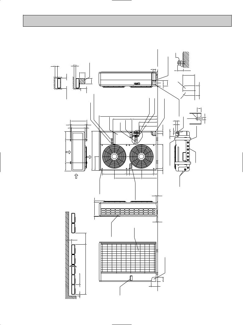
Outdoor Unit PUH24EK
Unit : mm
Outdoor Unit - necessary surrounding clearance
12
clearance |
The upper side must be open. |
Unit-Necessary surrouding |
(Concentrated installation) |
Outdoor |
|
Note:Allow adequate
1/2 upper clearance. |
opening |
|
3/8 |
Service space 36 |
|
|
|
|
|
|
|
|
3/8-2 |
outKnockholes for |
3/4-4 |
|
|
|
|
|
Standard bolt length |
9/16-2 |
-holespipingright |
|
|
|
4 |
|
N.E.C) (for |
|
|
|
|
|
|
|
2 - 1/16 |
1/16 - 1 line power |
|
|
|
|
|
|
|
|
|||
|
|
|
36 |
|
|
|
|
|
|
|
1 - 3/4 |
|
|
|
|
|
|
|
1 .max |
|
|
|
|
|
|
|
|
|
|
|
|
|
|
|
|
|
|
|
|
|
|
|
|
|
3-1/8 |
|
|
|
|
|
Front |
|
forblockTerminal |
connectionunit |
|
|
|
|
|
Refrigerantpipe |
(Flared)5/8F |
Refrigerantpipe (Flared)3/8F |
holeoutKnock pipingfrontfor |
|
|
wiring)and |
|
|
R13/16 |
|
|
|
|
detail figures |
1/2 |
|
line |
|
|
|
|
|
|
|
|
(refrigerant. anddrainagewiring) |
|
|
|
|
|||||||||
|
|
|
|
|
powerforblockTerminal |
|
|
|
|
|
|
|
|
drainage(refrigerant. |
|
|
|
R13/16 |
|
|
|
Front |
|
|
9/32 |
|
|
|
outdoorandindoor |
|
panelService |
Ground terminal |
Handie movingfor |
|
|
|
3/8-2 |
1/8-4 |
1/9/16 |
holeoutKnock |
pipingrightfor Bottom holepiping |
shaped-U-2 |
notched holes |
11/16 |
1/2 |
||||
|
|
|
|
|
|
|
|
|
49-1/2 |
|
|
|
|
|
|
|
|
|
|
R1/4 |
|
|
|
|
|
|
|
|
|
|
|
|
|
|
|
|
|
|
|
|
|
|
|
|
|
|
|
|
|
|
|
|
14-1/4 |
|
|
|
|
|
|
37-34 |
|
|
|
|
|
|
2-1/4 |
|
|
|
|
|
|
|
|
|
|
|
|
|
|
|
|
15-7/8 |
|
|
|
|
|
|
|
|
|
|
|
||||
|
|
|
|
|
|
|
|
|
|
|
|
|
|
|
|
|
|
|
|
|
||||
|
|
|
|
|
|
|
|
|
|
|
|
|
|
|
|
|
|
|
|
|
|
|||
11/16 |
|
13 |
9/16 |
|
|
|
|
|
15-1/16 |
|
|
|
2-1/16 |
|
|
|
|
|
|
|
||||
|
|
1-9/161-1/16 |
|
|
|
|
|
|
|
|
|
|
|
|
|
|
|
|
|
|
||||
|
|
|
|
|
|
|
|
|
|
|
|
|
|
|
|
|
|
|
|
|
|
|
||
7- |
|
|
|
|
|
|
|
|
|
|
|
|
|
|
|
1/2x7/8-2 Oval hoies |
M10)W3/8(M10)bolt(standard |
|
|
|
|
|
|
|
9/32-7 19-11/16 |
Air intake |
|
|
outletAir |
7/8-11 |
|
|
|
|
|
|
|
5/8-20 |
|
|
|
|
|
Drainhole |
|
|
|
||
|
|
|
|
1/434- |
|
|
|
|
|
|
|
|
|
|
|
|
|
|
|
|
|
|
|
|
|
|
|
intakeAir |
|
1 |
guideOutlet |
holeinstallation |
20-5/8 |
2-3/8 |
movingforHandle |
|
3-1/4 |
-9/16 |
|
|
|
|
|
holeDrain |
|
|
|
|
|
|
|
|
|
|
|
|
|
20-5/8 |
|
1 |
|
|
|
|
|
|
|
|
|
|
|
|||
|
|
|
|
|
|
|
|
|
23-1/16 |
|
13-9/16 |
|
|
|
|
|
|
|
|
|
|
|
|
|
|
|
|
|
|
|
|
|
|
|
|
|
|
2 |
|
|
|
|
|
|
|
|
|
|
|
|
|
|
|
|
11-5/8 |
|
|
|
|
|
|
|
|
|
|
|
|
|
|
|
|
|
|
|
|
|
|
|
|
1/4 |
|
|
|
|
|
|
|
|
|
|
|
|
|
|
|
|
|
|
|
|
|
|
|
|
|
|
|
Side air intake |
|
|
|
|
1 |
|
|
|
|
|
|
|
|
|
|
|
|
|
|
|
|
|
|
|
Rear fresh |
air intake |
|
|
|
|
|
|
|
|
|
|
|
|
|
|
|
|
|
12 |
40 |
|
|
|
|
|
|
|
|
|
|
|
|
|
|
|
|
|
|
|
|
|
|
|
|
|
|
|
|
|
|
|
|
|
|
|
|
|
|
|
|
|
|
|
|
|
|
|
|
|
10 units or less |
|
|
|
|
|
|
|
|
|
Rear piping hole |
|
|
|
|
|
|
|
|
|
|
|
|
|
|
For |
|
|
|
|
|
|
|
|
|
3-3/4 |
|
|
|
|
|
|
|
|
|
|
|
|
|
|
1/2 |
|
|
|
|
Handle formoving |
|
|
|
|
|
|
|
|
|
|
|
|
|
|
|
|
|
|
|
6 |
|
|
|
|
|
|
|
5-7/16 |
|
|
|
|
|
|
|
|
|
|
|
|
|
|
|
|
|
|
|
|
|
|
|
|
|
|
|
|
|
|
|
|
|
|
|
|
|
|
19
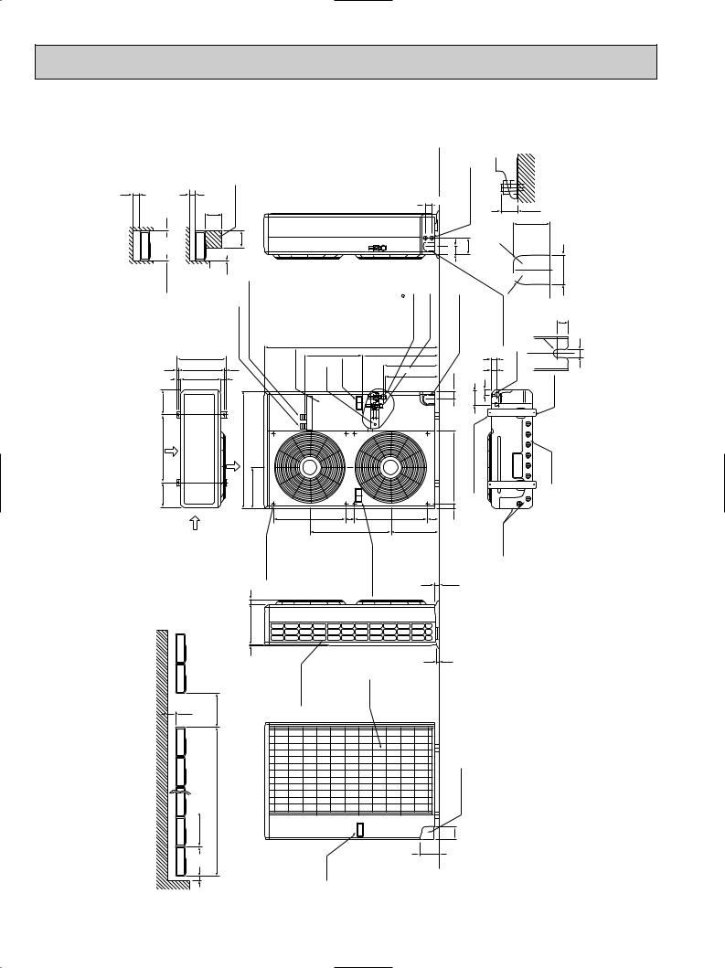
Outdoor Unit |
PUH30/36EK |
Unit : mm
clearance |
12 |
Outdoor Unit - necessary surrounding |
|
clearance |
The upper side must be open. |
Outdoor Unit-Necessary surrouding |
(Concentrated installation) |
Note:Allow adequate |
upper clearance. 1/2 |
opening |
|
1/2 |
Service space |
(for N.E.C) |
36 |
|
|
|
|
|
|
|
|
3/8-2 |
holes for |
3/4-4 |
|
|
|
|
|
Standard bolt length |
9/16-2 |
-holespipingright |
|
|
|
|
6 |
|
|
|
|
|
|
|
|
|
|
|
2 - 1/16 |
out line |
|
|
|
|
|
|
|
|
|
||
|
|
|
|
36 |
|
|
|
|
|
|
|
|
|
1 - 3/4 |
|
Knock |
power |
|
|
|
|
1 .max |
|
|
|
|
|
|
|
|
|
|
|
|
|
|
|
|
|
|
|
|
|
|
|
|
|
|
|
|
3-1/8 |
|
|
|
|
|
|
Front |
|
forblockTerminal |
outdoorandindoor connectionunit |
|
|
|
|
|
|
Refrigerantpipe |
(PUH30/36EK)3/4 |
(PUH42EK)7/8F |
Refrigerantpipe 3/8F(Flared) |
holeoutKnock pipingfrontfor |
|
wiring)and |
|
|
R13/16 |
|
|
|
|
detail figures |
|
|
1/2 |
|
|
line |
|
|
|
|
|
|
|
|
(refrigerant. anddrainagewiring) |
|
|
|
|
||||||||||
|
|
|
|
|
|
|
powerforblockTerminal |
|
|
|
|
|
|
|
|
|
drainage(refrigerant. 1/8-4 |
|
|
|
R13/16 |
|
|
|
Front |
|
|
|
|
|
|
|
|
|
|
panelService |
Ground terminal |
Handie movingfor |
(Flared) |
|
|
|
|
|
holeoutKnock |
pipingrightfor |
Bottom holepiping |
shaped-U-2 |
notched holes |
|
|
||||
|
9/32- |
|
|
|
|
|
|
|
|
|
3/8-2 |
1/9/16 |
11/16 |
1/2 |
|||||||||||||
|
|
|
|
|
|
|
|
|
|
|
49-1/2 |
|
|
|
|
|
|
|
|
|
|
|
|
R1/4 |
|
|
|
|
|
|
|
|
|
|
|
|
|
|
|
|
|
|
|
|
|
|
|
|
|
|
|
|
|
|
|
|
|
|
16-1/4 |
|
|
|
|
|
|
|
37-3/4 |
|
|
|
|
|
|
2-1/4 |
|
|
|
|
|
|
|
|
|
|
|
|
|
|
|
|
|
|
|
|
15-7/8 |
|
|
|
|
|
|
|
|
|
|
|
|||||
|
11/16 |
14-31/32 |
9/16 |
|
|
|
|
|
|
|
|
2-1/16 |
|
|
|
|
|
|
|
|
|||||||
|
|
|
|
|
|
|
15-1/16 |
|
|
|
|
|
|
|
|
|
|
||||||||||
|
|
|
1-1/16 |
1-9/16 |
|
|
|
|
|
|
|
|
|
|
|
|
|
|
|
|
|
|
|
|
|||
|
|
|
|
|
|
|
|
|
|
|
|
|
|
|
|
|
|
|
|
|
|
|
|
|
|
||
|
7 |
Air intake |
|
|
outletAir |
|
|
|
|
|
|
|
|
|
|
|
|
1/2x7/8-2 Oval hoies |
bolt(standardW3/8(M10) |
|
|
|
|
Drainhole |
|
|
|
|
9/32-7 23-5/8 |
|
|
|
7/8-13 |
|
|
|
|
|
|
|
|
5/8-20 |
|
|
|
|
|
|
|
|
|||||
|
|
|
|
|
3/1638- |
|
|
|
|
|
|
|
|
|
|
|
|
|
|
|
|
|
|
|
|
|
|
|
|
|
|
intakeAir |
|
|
1 |
guideOutlet |
holeinstallation |
20-5/8 |
2-3/8 |
movingforHandle |
|
|
3-1/4 |
-9/16 |
|
|
|
|
holeDrain |
|
|
|
|
|
|
|
|
|
|
|
|
|
|
|
|
20-5/8 |
|
|
1 |
|
|
|
|
|
|
|
|
|
|
|
|||
|
|
|
|
|
|
|
|
|
|
|
23-1/16 |
|
|
13-9/16 |
|
|
|
|
|
|
|
|
|
|
|
|
|
|
|
|
|
|
|
|
|
|
|
|
|
|
|
|
|
1-5/16 |
|
|
|
|
|
|
|
|
|
|
|
|
|
|
|
|
|
|
13-9/16 |
|
|
|
|
|
|
|
|
|
|
|
|
|
|
|
|
|
|
|
|
|
|
|
|
|
|
|
1/4 |
|
|
|
|
|
|
|
|
|
|
|
|
|
|
|
|
|
|
|
|
|
|
|
|
|
|
|
|
|
|
Side air intake |
|
|
|
|
|
7/8 |
|
|
|
|
|
|
|
|
|
|
|
|
|
|
|
40 |
|
|
|
|
|
Rear fresh |
air intake |
|
|
|
|
|
|
|
|
|
|
|
|
|
|
|
|
|
|
|
12 |
|
|
|
|
|
|
|
|
|
|
|
|
|
|
|
|
|
|
|
|
|
|
|
|
|
|
|
|
|
|
|
|
|
|
|
|
|
|
|
|
|
|
|
|
|
|
|
|
|
|
|
|
|
|
|
|
10 units or less |
|
|
|
|
|
|
|
|
|
|
|
Rear piping hole |
|
|
|
|
|
|
|
|
|
|
|
|
|
|
|
For |
|
|
|
|
|
|
|
|
|
|
|
|
|
|
|
|
|
|
|
|
|
|
|
|
|
|
1/2 |
|
|
|
|
|
|
Handle formoving |
|
|
|
|
|
3-3/4 |
|
|
|
|
|
|
|
|
|
|
|
|
|
|
6 |
|
|
|
|
|
|
|
|
|
|
5-7/16 |
|
|
|
|
|
|
|
|
|
|
|
|
|
20
Remote controller (PKH series)
Unit : mm
2-3/4
3-9/32
3-5/8 |
3-5/8 |
5/8 |
•CENTRALLY CONTROLLED•
S T A N D B Y |
ON |
D E F R O S T |
AUTO DRY HEAT COOL
CHECK 
 F SET TEMP
TIMER OFF 
 AUTO STOP
 AUTO START
 HR
HR
LOW HIGH
POWER — ON/OFF
HEAT |
AUTO |
COOL/DRY |
SET |
WARMER |
COOLER\ |
TEMPERATURE |
||
TIMER |
MODE |
HOURS |
FAN SPEED |
LOW/HIGH |
|
F AIR SWEEP |
AIR |
UP/DOWN SWING/STOP |
|
DISCHARGE |
|||
CHECK TEST RUN |
|
CHECK |
TEST RUN |
4-3/4
4-3/4
1/2
1/4-4 |
3/4-4 |
A |
|
|
5/32
Rear side wiring arrangement opening
Side wiring arrangement opening
5/16
3/16 |
3/8 |
2 |
|
Fixing holes |
1/4 |
VIEW A |
|
||
|
1/2 |
|
21

5 |
WIRING DIAGRAM |
|
|
|
|
|
|
|
|
|
|
|
|
|
|
|
|
|
||||||||
MODELS PKH18/24/30/36FK WIRING DIAGRAM |
|
|
|
|
|
|
L1 |
POWER SUPPLY |
|
|||||||||||||||||
|
|
|
|
|
|
|
|
|
|
|
|
|
|
|
|
|
|
|
|
|
|
|
|
|
||
|
|
|
|
|
|
|
|
|
|
|
|
|
|
|
|
|
|
|
|
|
|
|
L2 |
~(1 PHASE) |
|
|
|
|
|
|
|
|
|
|
|
|
|
|
|
|
|
|
|
|
|
|
|
|
|
|
AC208/230V 60Hz |
|
|
|
|
|
|
|
|
|
|
|
|
|
|
|
|
|
|
|
|
GRN/YLW |
|
|
|
GR |
|
|
|
|
|
|
MF |
|
|
|
|
|
|
|
230V |
|
10VAC |
|
|
|
|
|
|
|
|
GROUND |
|
||||
|
|
|
|
|
|
|
|
|
|
|
|
|
|
|
|
|
|
TB2 |
|
|
|
|||||
|
|
|
|
|
|
|
|
|
|
|
|
|
|
|
|
|
|
|
|
|
|
|
||||
|
|
|
|
|
|
|
|
|
YLW |
RED |
208V |
|
14.3VAC |
|
|
|
|
|
|
|
|
|
|
|||
|
|
C |
|
|
|
|
|
|
|
|
T |
|
|
|
|
|
6 |
|
|
MODELS |
18.24FK |
30.36FK |
|
|||
|
|
|
|
|
|
|
|
|
|
|
|
|
|
|
|
|
|
|
|
|
|
|
|
|||
|
|
RED WHT |
BLK |
|
|
|
RED |
BLE |
WHT YLW |
|
|
|
|
|
RED |
RED BRN |
BRN |
MV |
|
SW7 |
ON |
ON |
|
|||
|
I.B |
|
|
|
|
|
|
|
|
|
|
|
OFF |
OFF |
|
|||||||||||
|
|
|
|
|
|
|
|
|
|
|
|
|
|
1234 |
1234 |
|
||||||||||
|
|
|
|
|
|
|
|
|
|
|
|
|
|
|
|
|
|
|
|
|
|
|
|
|
||
|
FAN1 |
|
|
|
CND |
|
|
CNT |
|
6 |
1 |
4 |
3 2 |
1 |
CN4T |
|
|
|
|
TRANSMISSON WIRES |
|
|||||
|
|
|
|
POWER |
|
|
TRANS |
|
|
|
TRANS |
|
|
|
|
|
||||||||||
|
|
|
|
X4 |
|
F2 |
|
F1 |
|
|
|
CNGV |
|
|
PEMOCON |
CN30 CN22 2 1 2 OUTDOOR TO |
1 2 3 1 2 |
BLU |
TB5 |
2 |
DC12V |
|
|
|||
|
|
|
|
|
|
|
|
|
|
VANE |
|
|
BLU |
|
1 |
|
|
|
||||||||
|
|
|
|
|
|
|
|
|
|
|
|
|
|
|
|
|
|
|
||||||||
|
|
|
|
|
|
|
|
|
|
|
|
|
|
|
|
4 |
|
|
|
|
||||||
|
|
|
|
|
|
|
|
|
|
LED2 5V |
|
CN40 REMOCON POWER |
|
|
|
TB4 |
|
|
|
|
||||||
|
|
|
|
|
|
|
|
|
|
|
|
3 |
|
|
|
|
|
|
||||||||
|
|
|
|
|
|
|
|
|
|
POWER |
|
|
BRN |
3 |
TO OUTDOOR UNIT |
|
||||||||||
|
|
|
|
|
|
|
|
|
|
|
|
|
|
|
2 |
ORN |
|
2 |
|
|||||||
|
|
|
|
|
|
|
|
|
|
|
|
|
|
|
1 |
|
CONNECTING WIRES-POLAR |
|
||||||||
|
|
|
|
|
|
|
|
|
|
|
|
|
|
|
YLW |
|
1 |
DC12V |
|
|
||||||
|
|
|
|
|
|
|
|
|
|
|
|
CONTROL |
CN51 CENTRALLY |
|
|
|
|
|
||||||||
|
|
|
|
X4 |
|
|
|
|
|
|
|
|
|
|
|
|
|
|||||||||
|
|
|
|
ZNR |
|
|
LED1 12V |
|
|
|
|
|
|
R.B |
|
|
||||||||||
|
|
|
|
|
|
|
|
|
|
|
|
|
|
|
|
|
||||||||||
|
|
|
|
|
|
|
|
SW7 |
SW3 POWER |
|
|
CN21 |
|
|
RT2 |
1 2 3 |
TB6 |
|
||||||||
|
|
|
|
|
M.U.D |
CN27 |
|
|
ON |
|
|
|
PIPE |
|
|
|
|
|
||||||||
|
|
|
|
|
|
|
|
|
|
|
|
|
|
|
|
1 |
2 |
|||||||||
|
|
|
|
|
|
|
OFF |
|
|
|
|
|
|
|
|
CN2 |
||||||||||
|
|
|
|
|
|
|
|
|
|
CN20 |
|
|
RT1 |
|
|
|||||||||||
|
|
|
|
|
1234 |
12 |
|
|
|
|
|
LCD |
|
|
||||||||||||
|
|
|
|
|
|
|
|
|
|
|
5 |
|
|
1 |
|
|
|
|
|
|||||||
|
|
|
|
|
|
|
|
|
|
|
|
INTAKE |
|
|
|
|
|
|
|
|
|
|||||
|
|
SW2 |
J5 |
J9 |
SW6 |
|
J1 |
|
|
|
CN50 DRAIN |
4 |
|
|
|
LOSSNAY |
|
|
|
|
|
|
|
|
||
|
|
|
HEATER |
CN24 |
|
1 2 3 |
|
|
|
CN21 |
|
|
|
|
|
|
|
|||||||||
|
ON |
|
|
|
|
|
|
|
|
|
|
|
|
|
|
|
|
|
|
|
||||||
|
OFF |
|
|
|
|
|
|
|
|
|
|
|
|
|
|
|
|
CN1 |
|
|
||||||
|
|
123456 |
2 |
4 |
|
1234 |
|
|
4 5 6 7 8 9 |
|
|
|
|
|
|
|
|
1 2 3 4 5 6 |
|
|||||||
|
|
|
|
|
|
|
|
|
|
|
|
|
|
|
|
|
|
|
|
|||||||
|
|
|
|
|
|
|
|
|
|
|
|
|
|
|
|
|
|
|
|
|
|
|
|
|
SW17 |
|
|
|
|
|
|
|
|
|
RED |
88H RED |
FS1 |
FS2 |
H |
|
|
|
|
|
|
|
|
|
|
|
OFF |
||
|
|
|
|
|
|
TB2 |
|
3 |
5 BLU |
|
|
|
|
|
|
|
|
I.B |
8 |
88H |
7 |
5 |
GRY |
|
09876542321 |
ON |
|
|
|
|
|
|
|
|
|
|
|
|
|
|
|
|
BWN |
|
|
|
|
||||||
|
|
|
|
|
|
|
RED 4 |
6 |
|
|
|
|
|
|
|
|
|
|
|
|
|
|
||||
|
POWER SUPPLY |
|
L1 |
|
|
|
|
|
|
|
|
|
CN24 |
|
2 |
|
|
6 |
|
26H |
|
|
||||
|
|
|
|
|
BLU |
|
|
|
|
|
|
|
|
|
YLW |
|
|
|
|
|
|
|||||
|
~(1 PHASE) |
|
L2 GROUND |
|
|
|
|
|
|
|
HEATER |
|
1 |
|
|
|
|
|
|
|||||||
|
AC208/230V 60Hz |
|
GRN/YLW |
|
|
|
|
|
|
|
|
|
|
|
|
|
GRY |
|
|
|
||||||
|
|
|
|
GR |
|
|
|
|
|
|
|
|
|
|
|
|
|
|
|
|
|
|
|
|
|
|
SYMBOL |
|
|
|
|
|
NAME |
|
|
|
|
|
|
|
|
SYMBOL |
|
|
|
|
|
|
NAME |
|
|||
C |
FAN MOTOR CAPACITOR |
RT1 |
ROOM TEMP. THERMISTOR |
|
CN1<R.B> |
PROGRAM TIMER CONNECTOR |
(32°F / 15KΩ , 77°F / 5.4KΩ DETECT) |
||
|
||||
CN2<R.B> |
REMOTE SWITCH CONNECTOR |
RT2 |
INDOOR COIL THERMISTOR |
|
CN21<I.B> |
LOSSNAY CONNECTOR |
(32°F / 15KΩ , 77°F / 5.4KΩ DETECT) |
||
|
||||
|
|
|
|
|
CN27<I.B> |
DRAIN LIFT-UP MECHANISM CONNECTOR |
SW2<I.B> |
ADDRESS SELECTOR |
|
CN51<I.B> |
CENTRALLY CONTROL CONNECTOR |
SW3<I.B> |
EMERGENCY OPERATION |
|
|
|
|
|
|
F1,2<I.B> |
FUSE (6A 250V) |
SW6<I.B> |
MODEL SELECTOR |
|
|
|
|
|
|
FS1,2 |
THERMAL FUSE <243°F / 18, 24FK : 10A. 30.36FK : 16A> |
SW7<I.B> |
MODEL SELECTOR |
|
H |
HEATER |
SW17<I.B> |
ADDRESS SELECTOR |
|
|
|
|
|
|
I.B |
INDOOR CONTROLLER BOARD |
T |
TRANSFORMER |
|
|
|
|
|
|
J1 |
MODE SELECTOR JUMPER RESISTORS |
TB2 |
POWER TERMINAL BLOCK |
|
J5 |
MODE SELECTOR JUMPER RESISTORS |
TB4 |
INDOOR / OUTDOOR CONNECTING LINE TERMINAL BLOCK |
|
|
|
|
|
|
J9 |
MODE SELECTOR JUMPER RESISTORS |
TB5 |
REMOTE CONTROLLER TERMINAL BLOCK |
|
|
|
|
|
|
LCD<R.B> |
LIQUID CRYSTAL DISPLAY |
TB6 |
TRANSMISSION LINE |
|
LED1<I.B> |
LED (DC 12V POWER) |
X4<I.B> |
FAN MOTOR RELAY |
|
|
|
|
|
|
LED2<I.B> |
LED (DC 5V POWER) |
ZNR |
VARISTOR |
|
|
|
|
|
|
MF |
FAN MOTOR |
26H |
HEATER THERMAL SWITCH |
|
MV |
VANE MOTOR |
88H |
HEATER CONTACTOR |
|
|
|
|
|
|
R.B |
REMOTE CONTROLLER BOARD |
|
|
NOTES : |
|
|
|
|
|
|
|
|
|
|
|
|
|
|
|
|
|
||
1. |
Since the indoor fan motor (MF) is connected with 230V power, using 208V power will require a setting change of the dip switch (SW7<I.B>) on the indoor con- |
||||||||||||||||||
|
troller board as shown in fig : w 1. |
SW7 |
ON |
|
|
|
|
|
|
|
ON |
|
|
|
|
|
|||
|
|
fig w1 |
Indoor fan motor (MF) for 208V. |
OFF |
|
|
|
|
|
|
|
OFF |
|
|
|
|
|
||
|
|
|
|
|
1 |
2 3 4 |
|
|
|
1 |
2 3 4 |
|
|||||||
2. |
Since the indoor transformer (T) is connected with 230V power if 208V power is used. Change the wiring connection showing fig : w 2. |
||||||||||||||||||
|
|
fig w2 |
When power supply is |
|
|
|
|
|
|
|
|
|
|
|
|
|
|
|
|
|
|
|
|
|
|
|
|
240V |
YELLOW |
|
|||||||||
YELLOW 
 208V RED
230V
3.Since the outdoor side electric wiring may change be sure to check the outdoor unit electric wiring for servicing.
4.Indoor and outdoor connecting wires are made with polarities, make wiring matching terminal numbers.
5.Symbols used in wiring diagram above are, ¤¤ : Connector, /: Terminal block.
6.Emergency operation
If remote controller or microcomputer fails but there is no other trouble, emergency operation is possible by setting dip switch (SW3<I.B>) on the indoor controller board.
[Check items]
(1)Make sure that no other trouble exist the outdoor unit. Trouble with the outdoor unit prevents emergency operation.
(If any trouble exists the outdoor unit error code "P8" will be displayed on the remote controller and the trouble position will be shown on the outdoor controller board LED. See electric wiring diagram of the outdoor unit for details.)
(2)Make sure that there is no trouble with the indoor fan.
Emergency operation will be continuous operation mode due to power ON/OFF (ON/OFF with the remote controller is not possible). [Emergency operation procedure]
(1)Set the dip switch (SW3<I.B>) on the indoor controller board to 1 on and 2 off for cooling and 1 - 2 on for heating. (2)Turn on outdoor unit side circuit breaker, then indoor unit side circuit breaker.
(3)During emergency operation indoor fan runs at high speed but automatic vane remains stopped. If the air outlet is blocked up with the vane, Open it with your hands.
(4)Thermostat will not function. Cold air blows out for defrosting during heating thus do not operate defrosting for along time. (5)Emergency cooling should be limited to 10 hours maximum.
(The indoor unit heat exchanger may freeze).
(6)After every operation, switch the fan connector to FAN1, and set all dip switches (SW3<I.B>) to OFF.
BG79N687H01
22
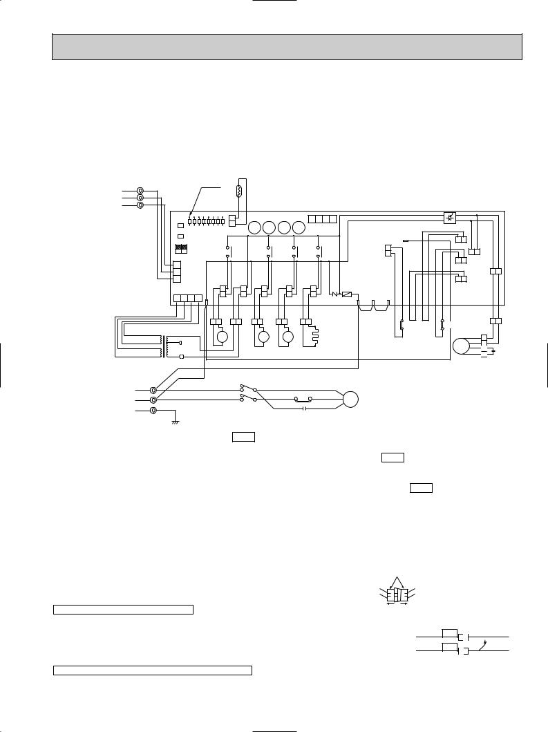
MODELS PUH18EK WIRING DIAGRAM
C |
COMPRESSOR CAPACITOR |
RT |
OUTDOOR COIL THERMSTOR |
X14<O.B> |
BYPASS VALVE RELAY |
C1 |
FAN CAPACITOR |
|
<32˚F/15kΩ ,77˚F/5.4kΩ > |
ZNR<O.B> |
VARISTOR |
F<O.B> |
FUSE<6A> |
SW1•2•3<0.B> |
SELECTOR<CHECK,SERVICE> |
21R |
BYPASS VALVE COIL |
|
|
|
|
|
|
FC<O.B> |
FAN CONTROLLER |
T |
TRANSFORMER |
21S4 |
R.V COIL |
HC |
CRANKCASE HEATER |
TB1,3 |
TERMINAL BLOCK |
51C |
OVERCURRENT RELAY |
|
|
|
|
|
|
LD1~LD8 |
LED<CHECK,SERVICE> |
X11<O.B> |
CRANKCASE HEATER RELAY |
52C |
CONTACTOR |
|
|
|
|
|
|
MC |
COMPRESSOR |
X12<O.B> |
COMPRESSOR RELAY |
63H1 |
CONTROL HIGH PRESSURE SWITCH |
|
|
|
|
|
|
MF |
FAN MOTOR<INNER THERMOSTAT> |
X13<O.B> |
R.V RELAY |
63H2 |
PROTECT HIGH PRESSURE SWITCH |
|
|
|
|
|
|
O.B |
OUTDOOR CONTROLLER BOARD |
|
|
|
|
|
1 |
YLW |
|
|
|
LED |
|
FROM INDOOR UNIT |
|
|
|
|
|
||
2 |
ORN |
|
|
|
|
|
|
CONNECTING WIRES |
|
|
|
|
|
||
3 |
BRN |
|
|
|
|
|
|
12V DC (polar) |
|
|
|
|
|
||
|
O.B |
|
|
|
|
|
|
|
TB3 |
|
|
|
|
|
|
|
|
|
|
|
|
|
|
|
|
SW1 |
LD1 LD2 LD3 LD4 LD5 LD6 LD7 LD8 |
||||
|
|
SW2 |
|||||
|
|
SW3 |
OFF |
|
|
||
|
|
|
|
|
|
||
|
|
2 |
1 |
ON |
|
|
|
|
|
|
|
|
|
||
|
|
3 |
|
|
|
|
|
|
|
2 |
CN3 |
|
|
|
|
|
|
1 |
|
|
|
|
|
|
|
|
CN4T |
|
4 |
|
|
|
|
4 |
3 |
2 |
1 |
SV |
|
|
|
|
|
|
|
|
|
|
|
|
|
|
|
RED |
RED |
|
|
|
|
|
|
RED |
RED |
|
BRN 12.3V AC RED |
208V |
|
21R |
|||
|
|
|
|||||
RT
|
|
|
|
|
|
4 |
3 |
2 |
1 |
|
|
CN2 |
X14 |
X13 |
X12 |
X11 |
|
CN4 |
|
|
|
||
|
|
|
|
|
|
|
|
|
|
|
|
X14 |
|
X13 |
|
X12 |
|
|
X11 |
63H1 |
|
||
|
|
|
|
|
|
||||||
|
|
|
|
|
|
|
|
|
F |
|
|
|
TRF |
21S4 |
|
52C |
CH |
|
ZNR R/1 S/2 |
T/3 |
|
||
WHT WHT |
BLK BLK |
|
GRY GRY |
S |
WHT WHT |
|
|
|
BLU |
BLU |
BRN |
|
BLK |
21 |
GRY |
GRY |
|
|
|
|
|
|
|
|
|
BLK |
|
A |
|
|
|
|
|
|
|
|
|
|
|
|
|
|
|
|
|
|
|
|
|
S4 |
|
52C |
|
|
HC |
|
|
|
|
|
|
|
|
|
|
|
|
|
|
|
|
|
|
|
|
B |
|
|
|
|
|
|
|
RED 12.3V AC |
ORN |
WHT |
|
|
|
|
|
|
WHT |
|
|
|
|
|
|||
|
T |
230V |
|
|
|
|
|
|
|
|
RED |
|
|
|
|
|
|
|
TB1 |
BLK |
|
|
|
|
|
|
|
|
|
52C |
BLU |
|
|
|
|
POWER SUPPLY |
L1 |
RED |
R |
U |
|
|
R |
|
|
|
|
|
WHT 2 |
51C 1 |
WHT C |
||
1{ 208/230V |
L2 |
BLK |
|
|
MC |
|||
|
|
T |
W |
BLU |
|
RED |
||
|
GR |
|
|
S |
||||
60Hz |
|
|
|
|
||||
|
|
|
|
|
|
|||
|
|
|
|
|
C |
|
||
|
|
|
|
|
|
|
||
|
|
GRN |
|
|
|
|
|
|
|
|
|
|
|
|
|
|
|
|
|
|
FC |
|
|
|
|
|
5 |
|
|
|
|
|
|
|
|
|
26C |
|
|
|
|
|
|
|
|
|
MF2 |
|
|
|
|
|
63H2 |
MF1 |
|
||
|
|
|
|
|
|||
|
|
|
51CM |
|
|
|
|
BRN |
YLW YLW YLW YLW RED |
RED |
BLU |
|
|
BLU |
WHT |
|
63H1 |
|
63H2 |
|
|
BLU |
WHT |
|
|
|
|
BLU |
4 |
||
|
|
|
MF |
WHT |
3 |
RED |
|
|
|
|
RED |
2 |
|||
|
|
|
|
|
|
C1 |
|
|
|
|
|
|
1 |
|
|
|
|
|
|
ORN |
ORN |
||
Main function of LED(when both Nos.1 and 2 of SW3 are "OFF")
LED NO. |
Output display (light) |
Check display (flash) |
|
|
|
|
|
LD1 |
Compressor indoor command |
— |
|
|
|
|
|
LD2 |
Heating indoor command |
— |
|
|
|
|
|
LD3 |
63H1 |
ON |
RT short/open |
|
|
|
|
LD4 |
Compressor |
ON |
63H2 funcitons |
|
|
|
|
LD5 |
Outdoor fan |
ON |
— |
|
|
|
|
LD6 |
R.V.coil |
ON |
— |
|
|
|
|
LD7 |
Bypass valve |
ON |
RT overheat protection |
|
|
|
|
LD8 |
Crankcase heater |
ON |
Defective input |
|
|
|
|
How to use SW1 and 2
●Pressing SW1 erases the past check contents loaded on the microcomputer.
●The output display (light) remains during opera-
tion but pressing SW2 displays the past check contents in flashing mode. Pressing the switch again retums to output display (light).
NOTES : 1. If the operation stops to function of the protection device, the check display flashes.
2. Symbols used in wiring diagram above are. /:Terminal block, ¤¤¤ :Connector, ¤ :PC board insertion tab.
CAUTION FOR SERVICING |
|
White connector |
|
s |
|
● The connector marked— |
¤— is to turn the compressor ON-OFF during servicing. |
|
The compressor stops by disconnecting the white connector as shown at the right.
CAUTIONS FOR POWER SUPPLY WIRING
● Since LD8 lights when normal power is turned "ON", check the power supply with the "ON" or "OFF" LD8.
wSince the indoor transformer (T) is connected with 230V power, if 208V power is used, change the wiring connection as shown in the right figure.
wWhen Power Supply is 208V
RED 208V |
WHITE |
ORANGE 230V |
|
CAUTION FOR INDOOR AND OUTDOOR CONNECTING WIRES
●Since the indoor and outdoor connecting wires has polarity, make sure to connect the same terminal numbers (1,2,3) for indoor and outdoor units.
23
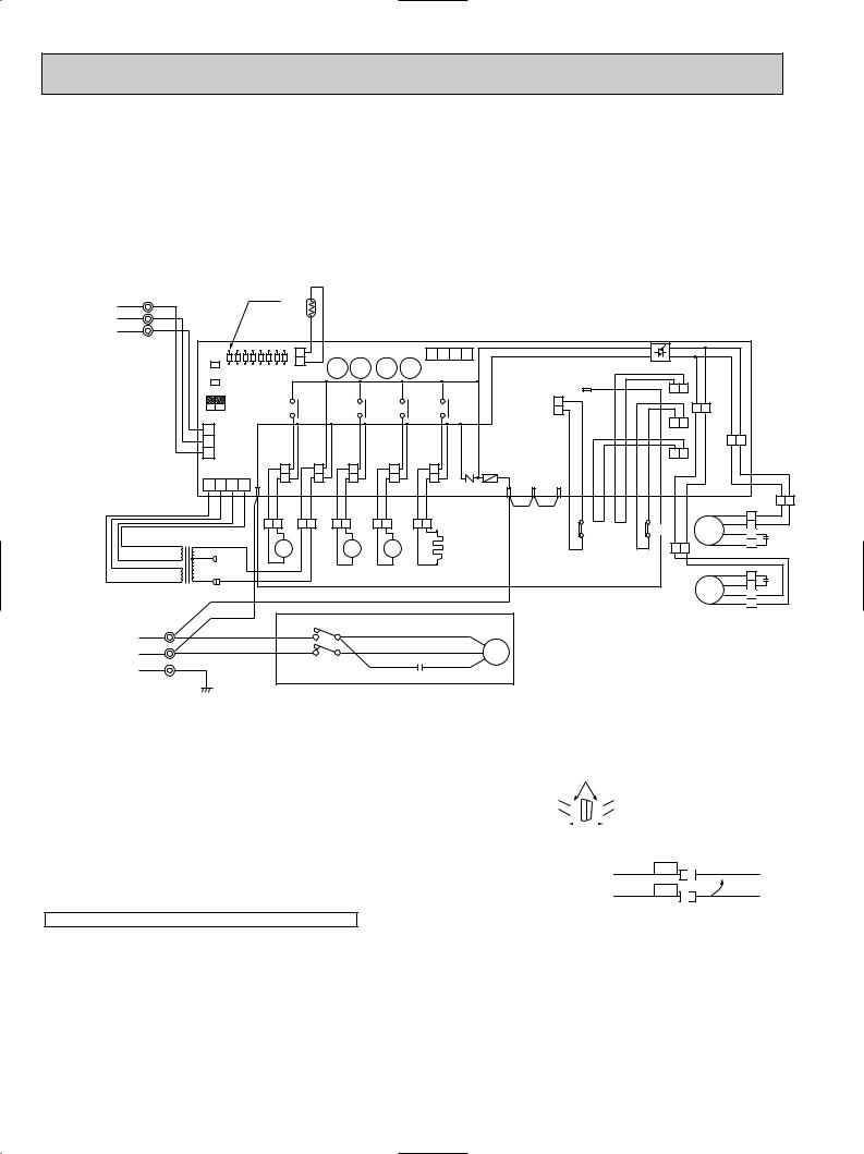
MODELS PUH24/30/36EK WIRING DIAGRAM
C |
COMPRESSOR CAPACITOR |
O.B |
OUTDOOR CONTROLLER BOARD |
X13<O.B> |
R.V RELAY |
|
C1,2 |
FAN CAPACITOR |
R |
RESISTOR |
X14<O.B> |
BYPASS VALVE RELAY |
|
|
|
|
|
|
|
|
C5 |
COMPRESSOR START CAPACITOR |
RT |
OUTDOOR COIL THERMISTOR |
ZNR<O.B> |
VARISTOR |
|
|
|
|
|
|
||
F<O.B> |
FUSE<6A> |
<32˚F/15kΩ , 77˚F/5.4kΩ > |
19 |
COMPRESSOR START RELAY |
||
|
||||||
FC<O.B> |
FAN CONTROLLER |
SW1•2•3<O.B> |
SELECTOR<CHECK,SERVICE> |
21R |
BYPASS VALVE COIL |
|
|
|
|
|
|
|
|
HC |
CRANKCASE HEATER |
T |
TRANSFORMER |
21S4 |
R.V COIL |
|
|
|
|
|
|
|
|
LD1~LD8 |
LED<CHECK,SERVICE> |
TB1,3 |
TERMINAL BLOCK |
52C |
CONTACTOR |
|
|
|
|
|
|
|
|
MC |
COMPRESSOR<INNER THERMOSTAT> |
X11<O.B> |
CRANKCASE HEATER RELAY |
63H1 |
CONTROL HIGH PRESSURE SWITCH |
|
|
|
|
|
|
|
|
MF1,2 |
FAN MOTOR<INNER THERMOSTAT> |
X12<O.B> |
COMPRESSOR RELAY |
63H2 |
PROTECT HIGH PRESSURE SWITCH |
|
1 |
YLW |
|
|
|
LED |
|
FROM INDOOR UNIT |
|
|
|
|
|
||
2 |
ORN |
|
|
|
|
|
|
CONNECTING WIRES |
|
|
|
|
|
||
3 |
BRN |
|
|
|
|
|
|
12V DC (poler) |
|
|
|
|
|
||
|
O.B |
|
|
|
|
|
|
|
TB3 |
|
|
|
|
|
|
|
|
|
|
|
|
|
|
|
|
SW1 |
LD1 LD2 LD3 LD4 LD5 LD6 LD7 LD8 |
||||
|
|
SW2 |
|||||
|
|
SW3 |
OFF |
|
|
||
|
|
|
|
|
|
||
|
|
2 1 |
ON |
|
|
|
|
|
|
|
|
|
|
||
|
|
3 |
|
|
|
|
|
|
|
2 |
CN3 |
|
|
|
|
|
|
1 |
|
|
|
|
|
|
|
|
CN4T |
|
4 |
|
|
|
|
4 |
3 |
2 |
1 |
SV |
|
|
|
|
|
|
|
|
|
|
|
|
|
|
|
RED |
RED |
|
|
|
|
|
|
RED |
RED |
|
BRN 12.3V AC RED |
208V |
|
21R |
|||
|
|
|
|||||
RT
CN2 X14 X13 X12 X11
X14 |
X13 |
X12 |
|
TRF |
21S4 |
|
52C |
|
|
WHT WHT |
BLK BLK |
|
GRY GRY |
S |
GRY |
WHT WHT |
|
BLK |
21 |
GRY |
|
||
|
|
BLK |
|
A |
|
|
|
|
|
|
|
|
|
|
|
S4 |
|
52C |
|
|
|
|
|
|
|
|
|
|
|
|
|
B |
|
|
4 |
3 |
2 |
1 |
|
|
|
CN4 |
|
|
|
|
|
|
X11 |
63H1 |
|
|
|
|
|
|
||
|
|
|
F |
|
|
CH |
|
ZNR R/1 S/2 |
T/3 |
|
|
|
|
|
BLU |
BLU |
BRN |
HC
RED 12.3V AC |
ORN |
WHT |
|
|
|
|
|
WHT |
|
|
|
|
|||
|
T |
230V |
|
|
|
|
|
|
|
RED |
|
|
|
|
|
|
TB1 |
BLK |
|
|
|
|
|
|
|
|
52C |
BLU |
|
|
|
POWER SUPPLY |
L1 |
RED |
R |
U |
|
R |
|
|
|
|
|
WHT |
WHT C |
||
1[ 208/230V |
L2 |
BLK |
|
|
MC |
||
|
|
T |
W |
BLU |
RED |
||
|
GR |
|
S |
||||
60Hz |
|
|
|
||||
|
|
|
|
|
|||
|
|
|
|
|
C |
||
|
|
|
|
|
|
||
|
|
GRN |
|
|
|
|
|
|
|
|
|
|
|
|
|
|
|
|
|
|
|
FC |
|
|
|
|
|
|
5 |
|
|
|
|
|
|
|
|
|
|
|
|
|
|
|
|
|
26C |
|
|
|
|
|
|
|
|
|
|
|
|
MF2 |
|
|
|
|
|
|
|
|
|
|
63H2 |
MF1 |
|
|
|
|
|
|
|
|
|
|
|
|
|
|
|
|
|
|
|
|
|
|
51CM |
|
|
|
WHT |
|
|
|
|
|
|
|
|
|
|
|
|
|
|
|
|
|
|
|
|
|
|
|
BLU |
BRN |
YLW |
YLW |
YLW YLW |
RED |
RED |
BLU |
BLU WHT |
|
BLU |
4 |
BLU |
|
|
|
|
|
|
63H2 |
MF1 |
WHT |
3 |
WHT |
|
|
63H1 |
|
|
|
RED |
2 |
RED |
||||
|
|
|
|
|
|
|
|
|
|
1 |
C1 |
|
|
|
|
|
|
|
|
|
ORN |
ORN |
|
|
|
|
|
|
|
|
|
|
|
||
YLW 1 |
YLW |
||
MF2 BRN |
2 |
C1 |
|
BRN |
|||
3 |
|||
WHT |
4 |
WHT |
|
BLU |
|
BLU |
|
NOTES : Symbols used in wiring diagram above are. /:Terminal block, ¤¤¤ :Connector, ¤ :PC board insertion tab.
CAUTION FOR SERVICING |
|
|
|
|
|
|
|
|
|
|
s ¤ |
White connector |
|||||||
● The connector marked— — is to turn the compressor ON-OFF during servicing. |
|
|
|
|
|
|
|
||
The compressor stops by disconnecting the white connector as shown at the right. |
|
|
|
|
|
|
|
||
|
|
|
|
|
|
|
|
|
|
|
|
|
|
|
|
|
|
|
|
|
|
|
|
|
|
|
|
|
|
|
|
|
|
|
|
|
|
|
|
CAUTION FOR POWER SUPPLY WIRING |
|
|
|
|
|
|
|
|
|
|
|
|
|
|
|
|
|
||
|
|
|
|
|
|
|
|
|
|
● Since LD8 lights when normal power is turned "ON", check the power supply with the "ON" or "OFF" LD8.
wSince the indoor transformer (T) is connected with 230V power, if 208V power is used, change the wiring connection as shown in the right figure.
CAUTION FOR INDOOR AND OUTDOOR CONNECTING WIRES
wWhen Power Supply is 208V
RED 208V |
WHITE |
ORANGE 230V |
|
●Since the indoor and outdoor connecting wires has polarity, make sure to connect the same terminal numbers (1,2,3) for indoor and outdoor units.
24

6 |
REFRIGERANT SYSTEM DIAGRAM |
|
|
|
|||||||
|
|
|
|
|
|
|
|
Control |
|
Protect |
|
|
|
|
|
|
|
|
|
|
high pressure |
|
|
PKH18FK |
|
|
|
|
|
|
high pressure |
|
|||
|
|
|
|
|
|
switch |
|
||||
|
|
|
|
|
Oil separator |
switch |
|
|
|||
|
|
|
|
|
|
|
|
||||
Indoor unit |
|
|
Refrigerant pipe |
|
|
|
Service |
Outdoor unit |
|
||
|
|
|
|
|
port |
|
|||||
|
|
|
|
(option) |
|
|
4-way valve |
|
|
COOL |
|
|
|
|
|
|
|
(check) |
|
|
|||
|
|
|
|
{5/8" |
|
|
|
|
|||
|
|
|
|
|
Ball valve |
|
|
|
|
HEAT |
|
|
|
|
|
(with heat insulator) |
|
|
|
|
|||
|
|
|
|
|
|
Strainer |
|
|
|
|
|
|
|
|
|
Flexible tube |
|
Service |
|
|
|
|
|
|
|
|
|
|
|
|
|
|
|
|
|
|
|
|
|
|
|
port |
|
|
|
|
Outdoor coil |
|
|
|
|
|
|
(check) |
|
|
|
|
thermistor |
|
|
|
|
Flared |
|
Fusible |
|
|
|
|
RT |
|
|
|
|
|
|
|
|
|
|
||
|
|
Strainer |
|
plug |
|
|
Bypass |
|
|||
|
|
connection |
|
|
|
|
|||||
|
|
|
|
|
|
|
|
|
|||
|
|
|
|
|
|
|
|
|
valve |
|
|
|
Indoor coil |
|
|
|
|
Accumulator |
|
|
Restrictor |
Capillary |
|
|
|
|
|
|
|
|
|
|
valve |
||
|
|
|
|
|
|
|
|
|
tube |
||
|
thermistor |
Restrictor |
|
|
|
|
Muffler Compressor |
|
|
||
|
|
|
|
|
|
|
({0.157x{0.079 |
||||
|
RT2 |
|
|
|
|
|
|
||||
|
valve |
|
|
|
|
|
|
|
|
x33.5) |
|
|
|
|
|
|
|
|
|
|
|
|
|
|
Distributor |
|
|
Refrigerant pipe |
|
Ball valve |
|
|
|
Strainer |
|
|
|
|
|
|
|
|
|
|
|||
|
|
Capillary |
|
(option) |
|
(with service port) |
|
|
|
|
|
|
|
|
{3/8" |
|
|
|
|
|
|
|
|
|
|
tube |
|
|
|
|
|
Protect |
|
|
|
|
|
|
(with heat insulator) |
|
|
|
|
|
|||
|
({0.126x{0.071x15.7) |
|
|
|
|
|
|
high pressure |
|
||
|
|
|
|
|
|
|
|
Control |
switch |
|
|
PKH24FK |
|
|
|
|
|
|
high pressure |
|
|
|
|
|
|
|
|
|
Oil separator |
switch |
Outdoor unit |
|
|||
Indoor unit |
|
Refrigerant pipe |
|
|
Service |
|
|||||
|
|
|
|
|
|
|
|||||
|
|
|
|
port |
|
|
|
||||
|
|
|
(option) |
|
4-way valve |
|
|
|
|||
|
|
|
|
(check) |
|
|
|
||||
|
|
|
{5/8" |
Ball valve |
|
|
|
|
|||
|
|
|
|
|
|
|
|
||||
|
|
|
(with heat insulator) |
|
|
|
|
|
|||
|
|
|
|
|
|
Strainer |
|
|
|
|
|
|
|
|
|
Flexible tube |
|
Service |
|
|
|
|
Outdoor coil |
|
|
|
|
|
|
port |
|
|
|
|
thermistor |
|
|
|
|
|
|
(check) |
|
|
|
|
RT |
|
|
|
|
Flared |
|
Fusible |
|
|
|
|
Restrictor |
|
|
Strainer |
|
|
plug |
|
|
|
|
||
|
|
|
|
|
|
Bypass |
|
valve |
|||
|
|
|
connection |
|
|
|
|
||||
|
|
|
|
|
|
|
|
||||
|
|
|
|
|
|
|
|
|
valve |
|
Capillary |
|
|
|
|
|
|
|
|
|
|
|
|
|
Indoor coil |
|
|
|
|
|
|
|
|
|
tube |
|
|
|
|
|
|
|
|
|
|
({0.126x{0.063 |
|
|
thermistor |
Restrictor |
|
|
|
|
Muffler Compressor |
|
|
||
|
|
|
|
Accumulator |
|
|
x17.3)x2 |
||||
|
RT2 |
|
|
|
|
|
|||||
|
valve |
|
|
|
|
|
|
|
|
|
|
Distributor |
Refrigerant pipe |
Ball valve |
Strainer |
|
|||
Capillary |
(option) |
(with service port) |
|
{3/8" |
|
|
tube |
(with heat insulator) |
|
({0.126x{0.071x9.8) |
|
|
|
|
|
Protect |
|
|
|
|
|
|
|
|
|
high pressure |
|
PKH-30/36FK |
|
|
|
|
|
Control |
switch |
|
|
|
|
|
|
high pressure |
|
||
Indoor unit |
|
|
|
Oil separator |
switch |
Outdoor unit |
|
|
|
Refrigerant pipe |
|
Service |
|
||||
|
|
|
|
|
|
|
||
|
|
(option) |
4-way valve |
|
port |
|
|
|
|
|
{3/4 |
|
(check) |
|
|
||
|
|
Ball valve |
|
|
|
|
||
|
|
(with heat insulator) |
|
|
|
|
|
|
|
|
|
Strainer |
|
|
|
|
|
|
|
Flexible tube |
Service |
|
|
|
|
Outdoor coil |
|
|
|
port |
|
|
|
|
thermistor |
|
|
|
(check) |
|
|
|
|
RT |
|
|
Flared |
Fusible |
|
|
|
|
Restrictor |
|
Strainer |
plug |
|
|
|
|
||
|
|
|
|
Bypass |
valve |
|||
|
connection |
|
|
|
||||
|
|
|
|
|
||||
|
|
|
|
|
|
|
valve |
Capillary tube |
|
|
|
|
|
|
|
|
|
Indoor coil |
|
|
|
|
|
|
|
PUH30EK |
|
|
|
Muffler |
|
|
|
({0.157x{0.079 |
|
thermistor |
Restrictor |
|
Accumulator |
Compressor |
Capillary tube |
|||
|
|
x23.6)x2 |
||||||
RT2 |
valve |
|
|
|
|
|
|
PUH36EK |
Distributor |
|
|
|
|
|
|
|
({0.157x{0.079 |
|
Refrigerant pipe |
Ball valve |
|
|
|
Strainer |
x17.7)x2 |
|
|
|
|
|
|
||||
|
Capillary |
(option) |
(with service port) |
|
|
|
|
|
|
{1/2" |
|
|
|
|
|
|
|
|
tube |
|
|
|
|
|
|
|
|
(with heat insulator) |
|
|
|
|
|
|
|
|
|
|
|
|
|
|
|
|
PKH30FK({0.157x{0.079x11.4) |
|
|
|
|
|
|
|
|
PKH36FK({0.157x{0.079x11.4) |
|
w Capillary tubesize:(ODxIDxLength) |
|
|||||
|
|
|
|
The symbol { indicates diameter. |
|
|||
25

7 
 OPERATION FLOW-CHART
MAIN OPERATION |
|
||
|
START |
|
|
|
Power circuit |
NO |
|
|
|
|
|
|
breaker |
|
|
1 |
YES |
|
|
YES |
Check SW |
|
|
|
ON twice |
|
|
|
NO |
w 1 |
|
|
|
|
|
|
Operation SW |
YES |
|
|
|
|
|
|
ON |
|
|
|
NO |
|
|
|
“OFF” timer |
YES |
|
|
|
|
|
|
NO |
|
|
NO |
“ON” timer |
Set time |
NO |
|
complete |
|
|
|
|
|
|
|
YES |
YES |
|
|
|
|
|
|
Set time |
YES |
|
|
complete |
|
w 2 |
|
NO |
|
NO |
|
|
|
Trouble |
|
YES |
Remote controller |
|
|
|
|
operation display |
|
|
STOP |
Trouble STOP |
Operating mode |
YES |
|
|
||||
|
|
(COOL) |
|
|
PROTECTION DEVICE |
PROTECTION DEVICE |
NO |
COOL operation |
|
SELF HOLD RELEASE |
SELF HOLD |
|
YES |
|
|
w 3 |
Operating mode |
||
|
|
|||
Remote controller |
(DRY) |
|
||
Remote controller |
|
|
||
indicator lamp OFF |
|
DRY operation |
||
trouble display |
NO |
|||
|
|
|||
|
|
Operating mode |
YES |
|
|
|
|
||
|
|
(HEAT) |
|
|
Indoor side |
|
NO |
HEAT operation |
|
|
w 4 |
|||
|
|
|||
|
w 6 |
|
||
Fan STOP |
|
YES |
||
|
Operating mode |
|||
|
|
(FAN) |
w 7 |
|
Auxiliary heater OFF |
|
NO |
FAN operation |
|
|
|
|||
|
|
|
||
|
|
Auto COOL/HEAT |
|
|
|
|
operation |
|
Outdoor side
w 5
Compressor OFF
Fan STOP
Four-way valve OFF
w1 In addition, the centralized and remote control can be operated. w2 The modes which indicate the sources of trouble are listed below.
●EO=Signal transmitting/receiving error
●P1=Room temperature thermistor malfunction
●P2=Indoor coil thermistor malfanction
●P4=Drain sensor malfunction
●P5=Drain over flow
●P6=Coil frost/overheat protection
●P7=System error
●P8=Outdoor unit trouble
w3 The CHECK swich will show if an error has occurred in the past. w4 Fan runs on low speed for 1 minute in order to remove overheat air.
w5 The 3-minute (6 minutes … heating mode) time-delay functions after compressor stops. w6 FAN or AUTO mode is selected by the indoor dipswitch setting.
w7 In FAN mode, fan speed and vane operation depend on the remote controller setting. (Compressor is OFF.) 26

COOLING OPERATION
COOL operation
Four-way valve/OFF
NO |
|
Initial |
|
|
COOLING |
|
w 8 |
YES |
|
Vane intial |
|
|
|
setting |
NO |
|
Vane |
60 deg downward angle |
||
|
70 deg downward angle |
|
|
NO |
YES |
|
Fan speed |
|
|
|
LOW |
|
|
YES |
|
NO |
|
|
Downward discharge |
|
|
|
1 hour |
|
|
YES |
Vane setting notch |
Vane horizontal |
|
|
|
|
|
|
||
|
airflow |
|
|
|
|
|
|
|
|
|
|
|
|
|
|
|
|
|
|
|
w 9 |
|
NO |
|
|
|
|
|
|
|
|
Compressor |
|
YES |
|
|
|
|
|
|
|
thermostat |
|
|
|
|
|
|
|
|
|
ON |
NO |
|
|
|
|
|
|
|
|
|
|
|
|
|
|
|
|
|
Allowance |
|
|
|
|
|
|
||
|
|
cancel |
|
|
|
|
|
|
|
|
|
NO YES |
3-minute |
|
|
|
|
|
|
|
|
|
|
time delay |
|
|
|
|
|
|
|
|
|
NO |
|
|
|
|
|
|
|
|
YES |
6-minute |
|
|
Aliowance |
YES |
|
|
|
|
|
time delay |
|
|
period |
|
|
|
|
|
|
NO |
|
|
NO |
|
|
|
|
|
|
|
|
6 minute |
|
|
|
|
|
|
|
|
|
|
|
|
|
|
|
|
NO |
3-minute |
|
|
time delay |
|
|
|
|
|
|
compressor opration |
|
|
|
|
|
|
|
|
|
YES |
|
|
Allowance set |
|
Coil frost protection |
|
|
|
|
|
|
|
|
|
|
|
|
|
|
w 10 |
YES |
|
|
|
|
|
|
|
|
Coil frost |
|
|
|
|
|
|
|
|
|
prevention |
|
|
|
|
|
|
|
|
|
NO |
|
|
|
|
|
|
|
|
w 11 |
|
NO |
|
|
|
|
|
|
|
|
Cooling area |
|
|
|
|
|
|
|
|
|
|
|
|
|
|
|
|
|
|
|
YES |
|
|
|
|
|
|
|
|
NO |
10-minute |
|
|
NO |
|
|
|
|
|
|
compressor operation |
|
|
1 min continue |
|
|
|
|
|
|
|
|
|
|
|
|
|
|
|
|
YES |
|
|
|
YES |
|
|
|
|
|
Allowance cancel |
|
|
|
|
|
|
|
|
|
|
|
|
FAN speed |
|
|
|
|
|
|
|
|
|
|
|
|
|
|
|
|
|
|
|
|
LOW |
|
|
|
|
|
Coil frost |
YES |
|
|
|
|
|
|
|
|
protection |
|
|
|
|
YES |
|
|
|
|
NO |
|
|
|
FAN speed |
|
|
|
|
|
|
|
|
LOW 5 min |
|
|
|
|
|
NO |
16-minute |
|
Indoor coil |
NO |
elapse |
|
|
|
|
|
NO |
|
||||
|
|
|
|
compressor operation |
|
tempreature is |
|
|
|
|
|
|
|
|
|
50°F or higher |
|
|
Outdoor unit |
|
|
|
|
YES |
|
YES |
|
|
trouble |
|
|
|
|
|
|
|
|
||
|
|
|
|
Indoor pipe |
YES |
3-minute |
|
|
|
|
|
|
|
temperature is |
|
time delay |
|
|
|
|
|
|
|
34°F or lower |
|
|
|
|
|
NO |
Coil frost |
Coil frost |
|
prevention |
prevention release |
Compressor ON Compressor OFF
1
w8 When operation stops or changes to cooling or dry mode, the auto vane turns to a horizontal angle. IF operation changes during auto vane SWING, the auto vane will continue to swing.
w9 When operating TEST RUN, the thermostat will be continuously ON.
w10After 3 minute compressor operation, if the indoor coil thermistor reads -59°F or below for 3 minutes, the compressor will stop for 6 minutes.
w11Cooling area : Indoor coil temperature is more than 9 degrees above the room temperature. Heating area : Indoor coil temperature is more than 9 degrees below the room temperature. FAN area : Indoor coil temperature is within 9 degrees either way of the room temperature.
27
 Loading...