


Air-Conditioners For Building Application
Hyper Heating Inverter Y-Series
OUTDOOR UNIT
PUHY-HP-THMU-A For use with R410A
INSTALLATION MANUAL
For safe and correct use, please read this installation manual thoroughly before installing the air-conditioner unit.
MANUEL D’INSTALLATION
Veuillez lire le manuel d’installation en entier avant d’installer ce climatiseur pour éviter tout accident et vous assurer d'une utilisation correcte.
F GB
GB
Contents
1. |
Safety precautions ...................................................................................... |
2 |
|
|
1.1. Before installation and electric work .......................................... |
2 |
|
|
1.2. Precautions for devices that use R410A refrigerant .................. |
2 |
|
|
1.3. |
Before installation ...................................................................... |
3 |
|
1.4. Before installation (relocation) - electrical work ......................... |
3 |
|
|
1.5. Before starting the test run ........................................................ |
3 |
|
2. |
About the product ....................................................................................... |
3 |
|
3. |
Combination of outdoor unit ........................................................................ |
4 |
|
4. |
Specifications .............................................................................................. |
4 |
|
5. |
Parts included list ........................................................................................ |
4 |
|
6. |
Space required for unit installation and operation ....................................... |
4 |
|
7. |
Transporting the unit ................................................................................... |
5 |
|
8. |
Installation of unit ........................................................................................ |
6 |
|
|
8.1. |
Installation ................................................................................. |
6 |
9. |
Refrigerant piping installation ..................................................................... |
6 |
|
|
9.1. |
Caution ...................................................................................... |
6 |
|
9.2. |
Refrigerant piping system .......................................................... |
7 |
10. |
Additional refrigerant charge ....................................................................... |
9 |
|
10.1. Calculation of additional refrigerant charge ............................... |
9 |
|
10.2. Precautions concerning piping connection and valve |
|
|
operation ................................................................................. |
10 |
|
10.3. Airtight test, evacuation, and refrigerant charging ................... |
11 |
|
10.4. Thermal insulation of refrigerant piping ................................... |
12 |
11. Wiring (For details, refer to the installation manual of each indoor/outdoor |
|
|
|
unit and controller.) ................................................................................... |
13 |
|
11.1. Caution .................................................................................... |
13 |
|
11.2. Control box and connecting position of wiring ......................... |
13 |
|
11.3. Wiring transmission cables ...................................................... |
13 |
|
11.4. Wiring of main power supply and equipment capacity ............ |
16 |
12. |
Test run/Typical unit operation .................................................................. |
17 |
13. |
Rating plate information ............................................................................ |
17 |
1. Safety precautions
1.1. Before installation and electric work
sBefore installing the unit, make sure you read all the “Safety precautions”.
sThe “Safety precautions” provide very important points regarding safety. Make sure you follow them.
Symbols used in the text
 Warning:
Describes precautions that should be observed to prevent danger of injury or death to the user.
 Caution:
Describes precautions that should be observed to prevent damage to the unit.
 Warning:
Carefully read the labels attached to the outdoor unit.
 Warning:
•Ask the dealer or an authorized technician to install the air conditioner.
-Improper installation by the user may result in water leakage, electric shock, or fire.
•Install the unit at a place that can withstand its weight.
-Failure to do so may cause the unit to fall down, resulting in injuries and damage to the unit.
•Use the specified cables for wiring. Make the connections securely so that the outside force of the cable is not applied to the terminals.
-Inadequate connection and fastening may generate heat and cause a fire.
•Prepare for strong winds and earthquakes and install the unit at the specified place.
-Improper installation may cause the unit to topple and result in injury and damage to the unit.
•When installing and moving the air conditioner to another site, do not charge it with a refrigerant different from the refrigerant specified on the unit.
-If a different refrigerant or air is mixed with the original refrigerant, the refrigerant cycle may malfunction and the unit may be damaged.
•If the air conditioner is installed in a small room, measures must be taken to prevent the refrigerant concentration from exceeding the safety limit if the refrigerant should leak.
-Consult the dealer regarding the appropriate measures to prevent the safety limit from being exceeded. Should the refrigerant leak and cause the safety limit to be exceeded, hazards due to lack of oxygen in the room could result.
•When moving and reinstalling the air conditioner, consult the dealer or an authorized technician.
-If the air conditioner is installed improperly, water leakage, electric shock, or fire may result.
•After completing installation work, make sure that refrigerant gas is not leaking.
-If the refrigerant gas leaks and is exposed to a fan heater, stove, oven, or other heat source, it may generate noxious gases.
•Do not reconstruct or change the settings of the protection devices.
-If the pressure switch, thermal switch, or other protection device is shorted or operated forcibly, or parts other than those specified by Mitsubishi Electric are used, fire or explosion may result.
•To dispose of this product, consult your dealer.
•The installer and system specialist shall secure safety against leakage according to local regulation or standards.
-Choose the appropriate wire size and the switch capacities for the main power supply described in this manual if local regulations are not available.
•Pay special attention to the place of installation, such as a basement, etc. where refrigeration gas can accumulate, since refrigerant is heavier than the air.
•For outdoor units that allow outside air intake to the indoor unit, the installation site must be carefully chosen to ensure only clean air can enter the room.
-Direct exposure to outdoor air may have harmful effects on people or food.
•Always use filters and other accessories specified by Mitsubishi Electric.
-Ask an authorized technician to install the accessories. Improper installation by the user may result in water leakage, electric shock, or fire.
•Never attempt to repair the unit without the proper qualifications. If the air conditioner must be repaired consult the dealer, contractor or qualified Refrigeration Engineer.
-If the unit is repaired improperly, water leakage, electric shock, or fire may result.
•Do not touch the heat exchanger fins.
-Improper handling may result in injury.
•If refrigerant gas leaks during installation work, ventilate the room.
-If the refrigerant gas comes into contact with a flame, poisonous gases will be released.
•Install the air conditioner according to this Installation Manual.
-If the unit is installed improperly, water leakage, electric shock, or fire may result.
•Have all electric work done by a licensed electrician according to “Electric Facility Engineering Standard” and “Interior Wire Regulations” and the instructions given in this manual and always use a dedicated power supply.
-If the power source capacity is inadequate or electric work is performed improperly, electric shock and fire may result.
•Securely install the outdoor unit terminal cover (panel).
-If the terminal cover (panel) is not installed properly, dust or water may enter the outdoor unit and fire or electric shock may result.
1.2.Precautions for devices that use R410A refrigerant
 Caution:
•Do not use existing refrigerant piping.
-The old refrigerant and refrigerant oil in the existing piping contains a large amount of chlorine which may cause the refrigerant oil of the new unit to deteriorate.
-R410A is a high-pressure refrigerant and can cause the existing piping to burst.
•Use refrigerant piping made of phosphorus deoxidized copper and copper alloy seamless pipes and tubes. In addition, be sure that the inner and outer surfaces of the pipes are clean and free of hazardous sulphur, oxides, dust/dirt, shaving particles, oils, moisture, or any other contaminant.
-Contaminants on the inside of the refrigerant piping may cause the refrigerant oil to deteriorate.
•Store the piping to be used during installation indoors and keep both ends of the piping sealed until just before brazing. (Store elbows and other joints in a plastic bag.)
-If dust, dirt, or water enters the refrigerant cycle, deterioration of the oil and compressor failure may result.
2

•Apply only a small amount of ester oil, ether oil, or alkyl benzene to flare connections (for indoor unit).
-Infiltration of a large amount of mineral oil may cause the refrigerant oil to deteriorate.
•Use liquid refrigerant to fill the system.
-If gas refrigerant is used to fill the system, the composition of the refrigerant in the cylinder will change and performance may drop.
•Do not use a refrigerant other than R410A.
-If another refrigerant (R22, etc.) is mixed with R410A, the chlorine in the refrigerant may cause the refrigerant oil to deteriorate.
•Use a vacuum pump with a reverse flow check valve.
-The vacuum pump oil may flow back into the refrigerant cycle and cause the refrigerant oil to deteriorate.
•Do not use the following tools that are used with conventional refrigerants.
(Gauge manifold, charge hose, gas leak detector, reverse flow check valve, refrigerant charge base, refrigerant recovery equipment)
-If the conventional refrigerant and refrigerant oil are mixed in the R410A, the refrigerant may deteriorate.
-If water is mixed in the R410A, the refrigerant oil may deteriorate.
-Since R410A does not contain any chlorine, gas leak detectors for conventional refrigerants will not react to it.
•Do not use a charging cylinder.
-Using a charging cylinder may cause the refrigerant to deteriorate.
•Be especially careful when managing the tools.
-If dust, dirt, or water gets into the refrigerant cycle, the refrigerant may deteriorate.
1.3. Before installation
 Caution:
•Do not install the unit where combustible gas may leak.
-If the gas leaks and accumulates around the unit, an explosion may result.
•Do not use the air conditioner where food, pets, plants, precision instruments, or artwork are kept.
-The quality of the food, etc. may deteriorate.
•Do not use the air conditioner in special environments.
-Oil, steam, sulfuric smoke, etc. can significantly reduce the performance of the air conditioner or damage its parts.
•When installing the unit in a hospital, communication station, or similar place, provide sufficient protection against noise.
-Inverter equipment, private power generator, high-frequency medical equipment, or radio communication equipment may cause the air conditioner to operate erroneously, or fail to operate. On the other hand, the air conditioner may affect such equipment by creating noise that disturbs medical treatment or image broadcasting.
•Do not install the unit on or over things that are subject to water damage.
-When the room humidity exceeds 80% or when the drain pipe is clogged, condensation may drip from the indoor unit. Perform collective drainage work together with the outdoor unit, as required.
1.4.Before installation (relocation) - electrical work
 Caution:
•Ground the unit.
-Do not connect the ground wire to gas or water pipes, lightning rods, or telephone ground lines. Improper grounding may result in electric shock.
•Install the power cable so that tension is not applied to the cable.
-Tension may cause the cable to break and generate heat and cause a fire.
•Install a leak circuit breaker, as required.
-If a leak circuit breaker is not installed, electric shock may result.
•Use power line cables of sufficient current carrying capacity and rating.
-Cables that are too small may leak, generate heat, and cause a fire.
•Use only a circuit breaker and fuse of the specified capacity.
-A fuse or circuit breaker of a larger capacity, or the use of a substitute simple steel or copper wire may result in a general unit failure or fire.
•Do not wash the air conditioner units.
-Washing them may cause an electric shock.
•Be careful that the installation base is not damaged by long use.
-If the damage is left uncorrected, the unit may fall and cause personal injury or property damage.
•Install the drain piping according to this Installation Manual to ensure proper drainage. Wrap thermal insulation around the pipes to prevent condensation.
-Improper drain piping may cause water leakage causing damage to furniture and other possessions.
•Be very careful about transporting the product.
-One person should not carry the product. Its weight is in excess of 20 kg [45LBS].
-Some products use PP bands for packaging. Do not use any PP bands as a means of transportation. It is dangerous.
-Do not touch the heat exchanger fins. Doing so may cut your fingers.
-When transporting the outdoor unit, support it at the specified positions on the unit base. Also support the outdoor unit at four points so that it cannot slip sideways.
•Safely dispose of the packing materials.
-Packing materials, such as nails and other metal or wooden parts, may cause stabs or other injuries.
-Tear apart and throw away plastic packaging bags so that children will not play with them. If children play with a plastic bag which has not been torn apart, they face the risk of suffocation.
1.5. Before starting the test run
 Caution:
•Turn on the power at least 12 hours before starting operation.
-Starting operation immediately after turning on the main power switch can result in irreversible damage to internal parts. Keep the power switch turned on during the operational season. Make sure of the phase order of power supply and voltage between each phase.
•Do not touch the switches with wet fingers.
-Touching a switch with wet fingers can result in an electric shock.
•Do not touch the refrigerant pipes during and immediately after operation.
-During and immediately after operation, the refrigerant pipes may be hot or cold, depending on the condition of the refrigerant flowing through the refrigerant piping, compressor, and other refrigerant cycle parts. Your hands may suffer burns or frostbite if you touch the refrigerant pipes.
•Do not operate the air conditioner with the panels and guards removed.
-Rotating, hot, or high-voltage parts can cause injuries.
•Do not turn off the power immediately after stopping operation.
-Always wait at least 5 minutes before turning off the power. Otherwise, drainage water leakage or mechanical failure of sensitive parts may occur.
•Do not touch the surface of the compressor during servicing.
-If the unit is connected to a supply and not running, the crank case heater located at the base of the compressor may still be operating.
GB
2. About the product
• This unit uses R410A-type refrigerant |
• Do not use the existing piping, as it contains chlorine, which is found in con- |
|
• Piping for systems using R410A may be different from that for systems using |
ventional refrigerating machine oil and refrigerant.This chlorine will deteriorate |
|
the refrigerant machine oil in the new equipment. The existing piping must not |
||
conventional refrigerant because the design pressure in systems using R410A |
||
be used as the design pressure in systems using R410A is higher than that in |
||
is higher. Refer to the Data Book for more information. |
||
the systems using other types of refrigerant and the existing pipes may burst. |
||
|
•Some of the tools and equipment used for installation with systems that use other types of refrigerant cannot be used with the systems using R410A. Refer to the Data Book for more information.
3
3. Combination of outdoor unit
Component units of PUHY-HP144 to HP192 are listed below.
Outdoor unit model |
|
Component unit models |
|
PUHY-HP72THMU-A(-BS) |
- |
|
- |
PUHY-HP96THMU-A(-BS) |
- |
|
- |
PUHY-HP144TSHMU-A(-BS) |
PUHY-HP72THMU-A(-BS) |
|
PUHY-HP72THMU-A(-BS) |
PUHY-HP192TSHMU-A(-BS) |
PUHY-HP96THMU-A(-BS) |
|
PUHY-HP96THMU-A(-BS) |
* PUHY-HP144/192TSHMU-A(-BS) require “Twinning Kit” to connect component unit modules in the field.
4. Specifications
|
|
Model |
|
|
|
|
PUHY-HP72THMU-A |
PUHY-HP96THMU-A |
|
PUHY-HP144TSHMU-A |
|
PUHY-HP192TSHMU-A |
||||||
|
|
Sound level (60Hz) |
56dB <A> |
57dB <A> |
|
59dB <A> |
|
|
|
60dB <A> |
||||||||
|
|
External static pressure |
|
|
|
|
0 Pa*2 |
|
|
|
|
|||||||
|
|
Indoor units |
|
Total capacity |
|
|
|
|
50 ~ 130%*1 |
|
|
|
|
|
||||
|
|
|
Model |
|
|
|
|
06 ~ 96 |
|
|
|
|
|
|||||
|
|
|
|
|
|
|
|
|
|
|
|
|
|
|
||||
|
|
|
|
|
|
Quantity |
1 ~ 13 |
|
1 ~ 16 |
|
|
1 ~ 22 |
|
|
1 ~ 24 |
|||
|
|
Operation |
|
|
Standard type |
Cooling mode: – 5°CDB ~ 43°CDB [23°FDB ~ 109°FDB] (0°CDB ~ 43°CDB [32°FDB ~ 109°FDB] with outdoor unit at lower position) |
||||||||||||
|
|
|
|
|
|
Heating mode: – 25°CWB ~ 15.5°CWB [–13°FWB ~ 60°FWB] |
|
|
|
|
||||||||
|
|
temperature |
|
|
|
|
|
|
|
|||||||||
GB |
|
|
|
|
|
|
|
|
|
|
|
|
|
|
|
|||
|
|
Outside air |
Cooling mode: 21°CDB/15.5°CWB ~ 43°CDB/35°CWB (70°FDB/60°FWB ~ 109°FDB/95°FWB) |
|
|
|||||||||||||
|
|
|
|
|
|
|
||||||||||||
|
|
|
|
|
intake type |
Heating mode: – 10°CDB ~ 20°CDB [14°FDB ~ 68°FDB] |
|
|
|
|
|
|
|
|||||
|
|
|
|
|
|
|
|
|
|
|
|
|
||||||
|
|
*1: The total indoor capacity of units run simultaneously is 130% or less. |
|
|
|
|
|
|
|
|||||||||
|
|
|
|
|
|
|
|
|||||||||||
|
|
*2: To enable high static pressure, set the DipSW on the main panel as follows. |
|
|
|
|
|
|
|
|||||||||
|
|
SW3-9: ON, SW3-10 60Pa compatible: OFF, 30Pa compatible: ON |
|
|
|
|
|
|
|
|||||||||
|
|
5. Parts included list |
|
|
|
|
|
|
|
|
|
|||||||
|
|
|
|
|
|
|
|
|
|
|
|
|
|
|
|
|
|
|
|
|
|
|
|
|
|
|
|
|
|
|
|
|
|
|
|
|
|
|
|
|
|
|
|
|
1 Connecting pipe (flare) |
2 Connecting pipe (flange) |
3 Connecting pipe (flare) |
|
4 Adapter |
|
5 Packing |
|||||
|
|
|
|
|
|
|
|
<Gas side> |
|
<Gas side> |
|
<Liquid side> |
|
<Check joint> |
|
(Inside ø23, Outside ø30) |
||
|
|
Model |
|
P72 |
|
|
1 pc. |
|
– |
|
1 pc. |
|
2 pcs. |
|
– |
|||
|
|
|
P96 |
|
|
– |
|
1 pc. |
|
1 pc. |
|
2 pcs. |
|
1 pc. |
||||
|
|
|
|
|
|
|
|
|
|
|||||||||
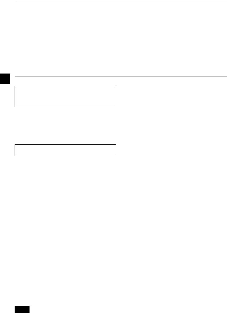
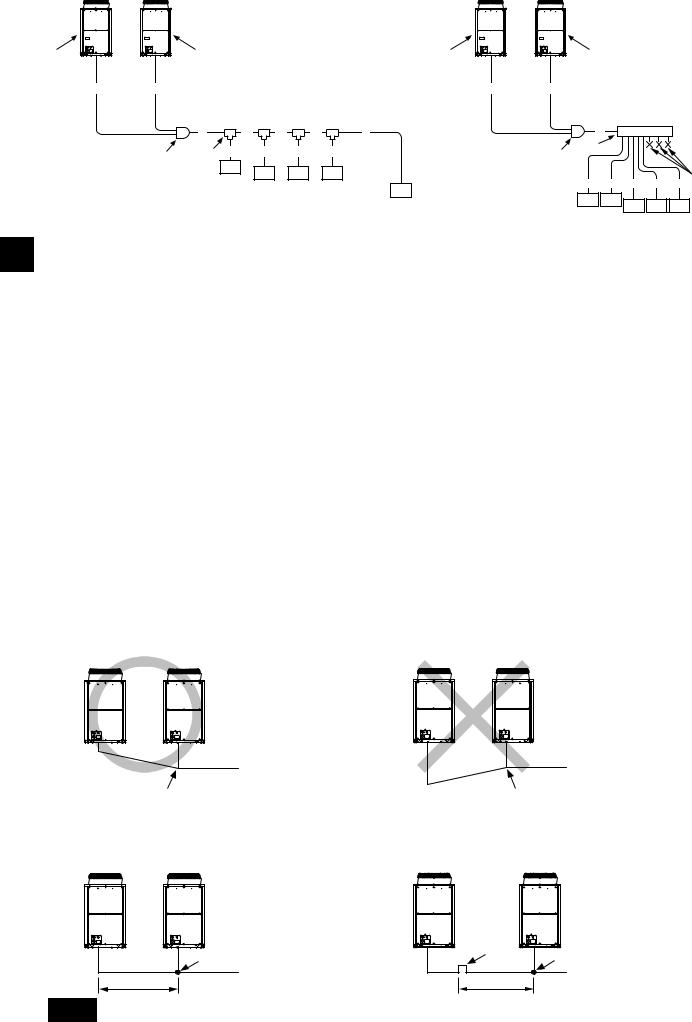
6. Space required for unit installation and operation
1 In case of single installation
•Secure enough space around the unit as shown in the figure below.
[Fig. 6.0.1]
(1)If the distance is 300 mm [11-13/16 in] or more between the rear side and the wall
<A> Top view
(Unit: mm [in])
 300*
300*
[11-13/16]
A 450*
450*
[17-23/32]
 15*
15*  15*
15*
[19/32] [19/32]
(3)If the wall height (H) of the front, rear or side exceeds the wall height restriction
<B> Side view
(Unit: mm [in])
h |
|
|
|
H |
h |
|
|
B |
[19-11/16] H |
||
A |
|||
|
|||
|
500 |
(2)If the distance is 100 mm [3-15/16 in] or more between the rear side and the wall
<A> Top view
(Unit: mm [in])
 100*
100*
[3-15/16]
A 450*
450*
[17-23/32]
 50*
50*  50*
50*
[1-31/32] [1-31/32]
•When the height of the walls on the front, back or on the sides <H> exceeds the wall height limit as defined here, add the height that exceeds the height limit <h> to the figures that are marked with an asterisk (*).
<Wall height limit> Front: Up to the unit height
|
Back: Up to 500mm [19-11/16 in] from the unit bottom |
|
|
Side: Up to the unit height |
|
(4) If there are obstacles at the upper part of the unit |
|
|
<C> When there is little space up to an obstruction |
|
|
|
|
(Unit: mm [in]) |
45° |
1000 |
|
|
[39-3/8] |
|
240 |
D |
|
[9-15/32] |
|
|
|
A |
C |
|
50 [1-31/32] |
|
A Front |
B Unit height |
|
C Back |
D Air outlet guide (field-supplied) |
|
4

2In case of collective installation and continuous installation [Fig. 6.0.2]
C |
300* |
[11-13/16] |
BB
A
C |
[1-3/16] |
450* |
23/32]- |
|
30 |
|
|
||
|
|
|
[17 |
|
C |
|
100* |
-15/16] |
|
|
|
|
[3 |
|
B |
|
|
B |
|
A |
|
450* |
23/32] |
|
C |
100 |
|||
|
|
|||
|
[3-15/16] |
|
- |
|
|
|
|
[17 |
B
C A A A C
450* |
450 |
450 |
100* |
[17-23/32] [17-23/32] [17-23/32] [3-15/16]
B
C |
15* |
[19/32] |
A A A
450 450 [17-23/32] [17-23/32]
(Unit: mm [in])
|
C |
300* |
[11-13/16] |
|
|
|
|
B |
A |
|
900 |
-7/16] |
B |
|
|
|
|
|
|
[35 |
|
|
|
|
C |
300* |
13/16] |
|
|
|
|
|
|
|
[11- |
|
|
|
|
|
|
C |
|
|
300* [11-13/16] |
|
|
|
|
A |
|
|
900 |
-7/16] |
B |
|
|
|
|
|
|
[35 |
|
|
1000* |
B |
|
|
|
|
|
|
|
|
|
|
|
|
|
|
[39-3/8] |
|
|
|
|
|
|
|
A Front |
|
|
|
B Must be open |
||
CWall height (H)
•When multiple units are installed adjacent to each other, secure enough space to allow for air circulation and walkway between groups of units as shown in the figures.
•At least two sides must be left open.
•As with the single installation, add the height that exceeds the height limit <h> to the figures that are marked with an asterisk (*).
GB
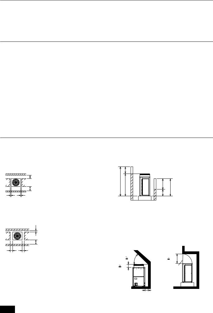
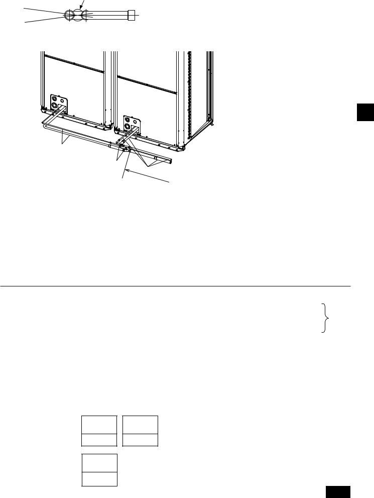
7. Transporting the unit
[Fig. 7.0.1]
(Unit: m [ft])
 40
40
 8 [26]
 8 [26]
•Use suspension ropes that will withstand the weight of the unit.
•When moving the unit, use a 4-point suspension, and avoid giving impacts to the unit (Do not use 2-point suspension).
•Place protective pads on the unit where it comes in contact with the ropes to protect the unit from being scratched.
•Set the angle of roping at 40˚ or less.
•Use 2 ropes that are each longer than 8 m [26ft].
•Place protective padding at the corners of the product to protect the product from scratches or dents that might be caused by the rope.
 Caution:
Be very careful when carrying/moving the product.
-When installing the outdoor unit, suspend the unit at the specified location of the unit base. Stabilize as necessary so that it does not move to the side and support it at 4 points. If the unit is installed or suspended with 3-point support, the unit may become unstable and fall.
5
GB
8. Installation of unit
8.1. Installation
[Fig. 8.1.1]
(Unit: mm [in])
30 [1-3/16]
 A
A
B
C
A Field-supplied M10 anchor bolt |
B Corner is not seated. |
CFixing bracket for the hole-in anchor bolt (3 locations to fix with screws)
[Fig. 8.1.2]
Outlet
Inlet 

 Inlet
Inlet 
 Inlet
Inlet
H
•In abnormally harsh environments such as clod and/or windy areas, sufficient countermeasures to guard against excessive wind and snow should be taken to ensure the unit's correct operation. When the unit is expected to operate in cooling mode in conditions under 10°C [50°F], in snowy areas, in environments subject to strong winds or rain, install air inlet and outlet ducting as shown in
[Fig. 8.1.2].
•Fix unit tightly with bolts so that unit will not fall down due to earthquakes or strong winds.
•Use concrete base or an angle bracket as the foundation of unit.
•Vibration may be transmitted to the installation section and noise and vibration may be generated from the floor and walls, depending on the installation conditions. Therefore, provide ample vibrationproofing (cushion pads, cushion frame, etc.).
•Be sure that the corners are firmly seated. If the corners are not firmly seated, the installation feet may be bent.
•The projecting length of the anchor bolt should be less than 30 mm [1-3/16 in].
•Post-installed anchor bolts (i.e., bolts not firmly cemented into the base) are not compatible with this product unless fixing brackets are first mounted on the four locations.
Note:
1.Height of frame base for snow damage prevention (H) shall be twice as high as expected snowfall. Width of frame base shall not exceed that of the unit. The frame base shall be made of angle steel, etc., and designed so that snow and wind slip through the structure. (If frame base is too wide, snow will be accumulated on it.)
2.Install unit so that wind will not directly lash against openings of inlet and outlet ducts.
3.Build frame base at customer referring to this figure.
Material : Galvanized steel plate 1.2T
Painting : Overall painting with polyester powder
Color : Munsell 5Y8/1 (same as that of unit)
4.When the unit is used in a cold region and the heating operation is continuously performed for a long time when the outside air temperature is below freezing, install a heater to the unit base or take other appropriate measures to prevent water from freezing on the base.
 Warning:
•Be sure to install unit in a place strong enough to withstand its weight.
Any lack of strength may cause unit to fall down, resulting in a personal injury.
•Have installation work in order to protect against strong winds and earthquakes. Any installation deficiency may cause unit to fall down, resulting in a personal injury.
When building the foundation, give full attention to the floor strength, drain water disposal <during operation, drain water flows out of the unit>, and piping and wiring routes.
Precautions when routing the pipes and wires below the unit (Without detachable leg)
When routing the pipes and wires below the unit, be sure that the foundation and base work do not block the base through-holes. Also make sure the foundation is at least 100 mm [3-15/16 in] high so that the piping can pass under the unit.
9. Refrigerant piping installation
The pipe is connected via a terminal-branch type connection in which refrigerant piping from the outdoor unit is branched at the terminal and is connected to each of the indoor units.
The method of pipe connection is as follows: flare connection for the indoor units, gas pipes for outdoor units, flare connection for P72 and brazed connection for P96 ~ P192; liquid pipes, flare connection. Note that the branched sections are brazed.
 Warning:
Always use extreme care to prevent the refrigerant gas from leaking while using fire or flame. If the refrigerant gas comes in to contact with a flame from any source, such as a gas stove, it breaks down and generates a poisonous gas which can cause gas poisoning. Never weld in an unventilated room. Always conduct an inspection for gas leakage after installation of the refrigerant piping has been completed.
9.1. Caution
This unit uses refrigerant R410A. Follow the local regulations on materials and pipe thickness when selecting pipes. (Refer to the table on page 7.)
1Use the following materials for refrigeration piping.
•Material: Use copper alloy seamless pipes made of phosphorus deoxidized copper. Ensure the inner and outer surfaces of the pipes are clean and free from hazardous sulfur, oxide, dusts, shaving particles, oils, and moisture (contamination).
•Size: Refer to item 9.2. for detailed information on refrigerant piping system.
2Always observe the restrictions on the refrigerant piping (such as rated length, height difference, and piping diameter) to prevent equipment failure or a decline in heating/cooling performance.
6
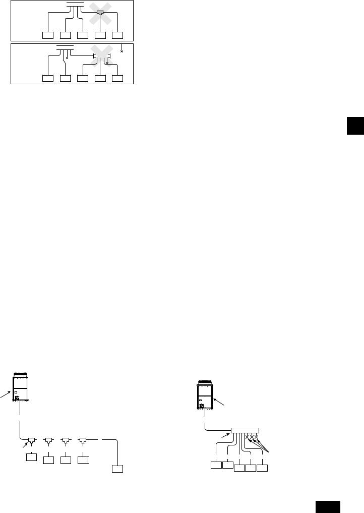
3Branching cannot be made after header branching (corresponding parts are marked with  in the diagram below).
To the outdoor unit 


To the outdoor unit 


CAP
4 Do not install outdoor unit piping when it is raining.
5Commercially available piping often contains dust and other materials. Always blow it clean with a dry inert gas.
6Use care to prevent dust, water or other contaminants from entering the piping during installation.
7Reduce the number of bending portions as much as possible, and make bending radius as big as possible.
8For indoor and outdoor branching, be sure to use the following twinning pipe sets (sold separately).
9Use an adapter if a specified refrigerant pipe has a different diameter from that of a branching pipe.
0Braze only with non-oxide brazing material for piping. Failure to do so may damage the compressor. Be sure to perform the non-oxidation brazing with a nitrogen purge.
Do not use any commercially available anti-oxidizing agent since it may cause pipe corrosion and degrading of the refrigerant oil.
Please contact Mitsubishi Electric for more details.
(Refer to item 10.2. for details of the piping connection and valve operation)
AAlways insulate the piping properly. Insufficient insulation will result in a decline in heating/cooling performance, water drops from condensation forming and other such problems. (Refer to item 9 for installation of refrigerant piping.)
BWhen connecting the refrigerant piping, make sure the valve of the outdoor unit is completely closed (the factory setting). Do not operate it until the refrigerant piping for the outdoor and indoor units has been connected, a refrigerant leakage test has been performed, and the evacuation process has been completed.
CNever use refrigerant to perform an air purge. Always evacuate using a vacuum pump.
D Be sure to charge the system using liquid refrigerant.
EEither a lack or an excess of refrigerant causes the unit to make an emergency stop. Charge the system with an appropriate amount of refrigerant. When servicing, always check the notes concerning pipe length and amount of additional refrigerant at both locations, the refrigerant volume calculation table on the back of the service panel and the additional refrigerant section on the labels for the combined number of indoor units. (Refer to item 9.2. for detailed information on refrigerant piping system.)
|
|
Indoor twinning pipe set model |
|
|
Outdoor Twinning Kit model |
||
|
Line branch |
|
|
Header branch |
|
|
|
Downstream indoor unit capacity |
Downstream indoor unit capacity |
Downstream indoor unit capacity |
|
|
|
Total outdoor model |
|
More than 73 and less than |
More than 145 and less than |
4 branches |
8 branches |
10 branches |
|||
Less than 72 in total |
P144 ~ P192 |
||||||
144 in total |
288 in total |
|
|
|
|||
|
|
|
|
|
|||
CMY-Y102S-G2 |
CMY-Y102L-G2 |
CMY-Y202-G2 |
CMY-Y104-G |
CMY-Y108G |
CMY-Y1010-G |
CMY-Y100VBK2 |
|
 Warning:
When installing and moving the unit, do not charge the system with any other refrigerant other than the refrigerant specified on the unit.
-Mixing of a different refrigerant, air, etc. may cause the refrigerant cycle to malfunction and may result in severe damage.
 Caution:
•Use a vacuum pump with a reverse flow check valve.
-If the vacuum pump does not have a reverse flow check valve, the vacuum pump oil may flow back into the refrigerant cycle and cause deterioration of the refrigerant oil.
•Do not use the tools shown below used with conventional refrigerant. (Gauge manifold, charge hose, gas leak detector, check valve, refrigerant charge base, vacuum gauge, refrigerant recovery equipment)
-Mixing of conventional refrigerant and refrigerator oil may cause the refrigerant oil to deteriorate.
-Mixing of water will cause the refrigerant oil to deteriorate.
-R410A refrigerant does not contain any chlorine. Therefore, gas leak detectors for conventional refrigerants will not react to it.
•Manage the tools used for R410A more carefully than normal.
-If dust, dirt, or water gets in the refrigerant cycle, the refrigerant oil will deteriorate.
•Never use existing refrigerant piping.
-The large amount of chlorine in conventional refrigerant and refrigerant oil in the existing piping will cause the new refrigerant to deteriorate.
•Store the piping to be used during installation indoors and keep both ends of the piping sealed until just before brazing.
-If dust, dirt, or water gets into the refrigerant cycle, the oil will deteriorate and the compressor may fail.
•Do not use a charging cylinder.
-Using a charging cylinder may cause the refrigerant to deteriorate.
•Do not use special detergents for washing piping.
9.2. Refrigerant piping system
Connection Example
[Fig. 9.2.1]
[Outdoor model : P72 ~ P96]
A
|
|
|
|
|
A |
|
|
|
A |
|
|
|
A |
|
|
|
|
|
|
|
|
|
|
|
|
|
|
|
|
|
|
|
|
F |
|
B |
C |
D |
e |
B |
|
|
|
|
B a |
b |
c |
d |
|
|
|
|
|
C |
C |
C |
C |
a |
b c |
d |
e D |
|
|
|
|
|
|
|
|||
|
|
|
|
C |
C |
C |
C |
C |
|
|
|
|
C |
|
|||
|
|
|
|
|
|
|
|
|
GB
7
GB
[Outdoor model : P144 ~ P192]
unit 1 |
unit 2 |
|
|
|
|
unit 1 |
unit 2 |
|
|
|
|
A |
|
A |
|
|
|
A |
A |
|
|
|
|
A1 |
A2 |
|
|
|
|
A1 |
A2 |
|
|
|
|
|
|
A |
B |
C |
D |
e |
A |
|
|
F |
|
|
|
B |
a |
b |
c |
d |
B |
|
|
|
|
|
E |
E |
|
|
|
|
|||||
|
|
|
C |
C |
C |
C |
|
|
|
|
|
|
|
|
|
|
|
|
|
e D |
|||
|
|
|
|
|
|
C |
a |
b c |
d |
||
|
|
|
|
|
|
C |
C |
|
|
|
|
|
|
|
|
|
|
|
C |
C |
C |
||
|
|
|
|
|
|
|
|
|
|||
A Outdoor unit |
|
B 1st branch |
|
|
|
|
|
|
|
||
C Indoor unit |
|
|
D Cap |
|
|
|
|
|
|
|
|
E Outdoor Twinning Kit |
|
F Header |
|
|
|
|
|
|
|
||
* The total length of A1 and A2 is less than 10 m [32 ft].
A |
|
|
|
|
|
|
|
(Unit: mm [in]) |
Outdoor model |
Unit combination |
|
A |
|
A1 |
|
A2 |
|
|
unit 1 |
unit 2 |
Liquid pipe |
Gas pipe |
Liquid pipe |
Gas pipe |
Liquid pipe |
Gas pipe |
P72 |
- |
- |
ø12.7 [1/2] Brazed |
ø19.05 [3/4] Brazed |
- |
- |
- |
- |
|
|
|
|
|
|
|
|
|
P96 |
- |
- |
ø12.7 [1/2] Brazed |
ø22.2 [7/8] Brazed |
- |
- |
- |
- |
P144 |
P72 |
P72 |
ø15.88 [5/8] Brazed |
ø28.58 [1-1/8] Brazed |
ø9.52 [3/8] Flare |
ø19.05 [3/4] Brazed |
ø9.52 [3/8] Flare |
ø19.05 [3/4] Brazed |
P192 |
P96 |
P96 |
ø15.88 [5/8] Brazed |
ø28.58 [1-1/8] Brazed |
ø9.52 [3/8] Flare |
ø22.2 [7/8] Brazed |
ø9.52 [3/8] Flare |
ø22.2 [7/8] Brazed |
|
B, C, D |
|
|
|
(Unit: mm [in]) |
|
|
|
|
|
|
|
|
|
Total capacity of indoor units |
|
Liquid pipe |
|
Gas pipe |
|
|
~ 54 |
|
|
ø9.52 [3/8] |
|
ø15.88 [5/8] |
|
55 ~ 72 |
|
|
ø9.52 [3/8] |
|
ø19.05 [3/4] |
|
73 ~ 108 |
|
|
ø9.52 [3/8] |
|
ø22.2 [7/8] |
|
109 ~ 144 |
|
|
ø12.7 [1/2] |
|
ø28.58 [1-1/8] |
|
145 ~ 234 |
|
|
ø15.88 [5/8] |
|
ø28.58 [1-1/8] |
|
|
|
|
|
|
|
a, b, c, d, e |
|
|
|
(Unit: mm [in]) |
||
|
|
|
|
|
|
|
|
Model number |
|
Liquid pipe |
|
Gas pipe |
|
|
06, 08, 12, 15, 18 |
|
ø6.35 [1/4] |
ø12.7 [1/2] |
||
|
24, 27, 30, 36, 48, 54 |
|
ø9.52 [3/8] |
ø15.88 [5/8] |
||
|
72 |
|
ø9.52 [3/8] |
ø19.05 [3/4] |
||
|
96 |
|
ø9.52 [3/8] |
ø22.2 [7/8] |
||
|
|
|
|
|
|
|
Precautions for outdoor unit combinations
Refer to [Fig. 9.2.2] for the positioning of twinning pipes.
[Fig. 9.2.2]
Downstream unit model total |
|
|
|
Joint |
|
|
||
~ 72 |
|
|
|
CMY-Y102S-G2 |
|
|
||
73 ~ 144 |
|
|
|
CMY-Y102L-G2 |
|
|
||
145 ~ 234 |
|
|
|
|
CMY-Y202-G2 |
|
|
|
The 1st branch of P144 ~ P234 |
|
|
|
|
||||
|
|
|
|
|
|
|||
|
|
|
|
|
|
|||
|
|
|
|
|
|
|||
4-Branch header |
|
8-Branch header |
|
10-Branch header |
||||
(Downstream indoor |
|
(Downstream indoor |
|
(Downstream indoor |
||||
< |
|
< |
144) |
|
unit model total |
< |
234) |
|
unit model total = 72) |
|
unit model total = |
|
= |
||||
CMY-Y104-G |
|
CMY-Y108-G |
|
|
CMY-Y1010-G |
|||
|
|
|
|
|
|
|||
Outdoor model |
|
|
Outdoor Twinning Kit |
|
|
|||
P144 ~ P192 |
|
|
CMY-Y100VBK2 |
|
|
|||
|
|
|
|
|
|
|
|
|
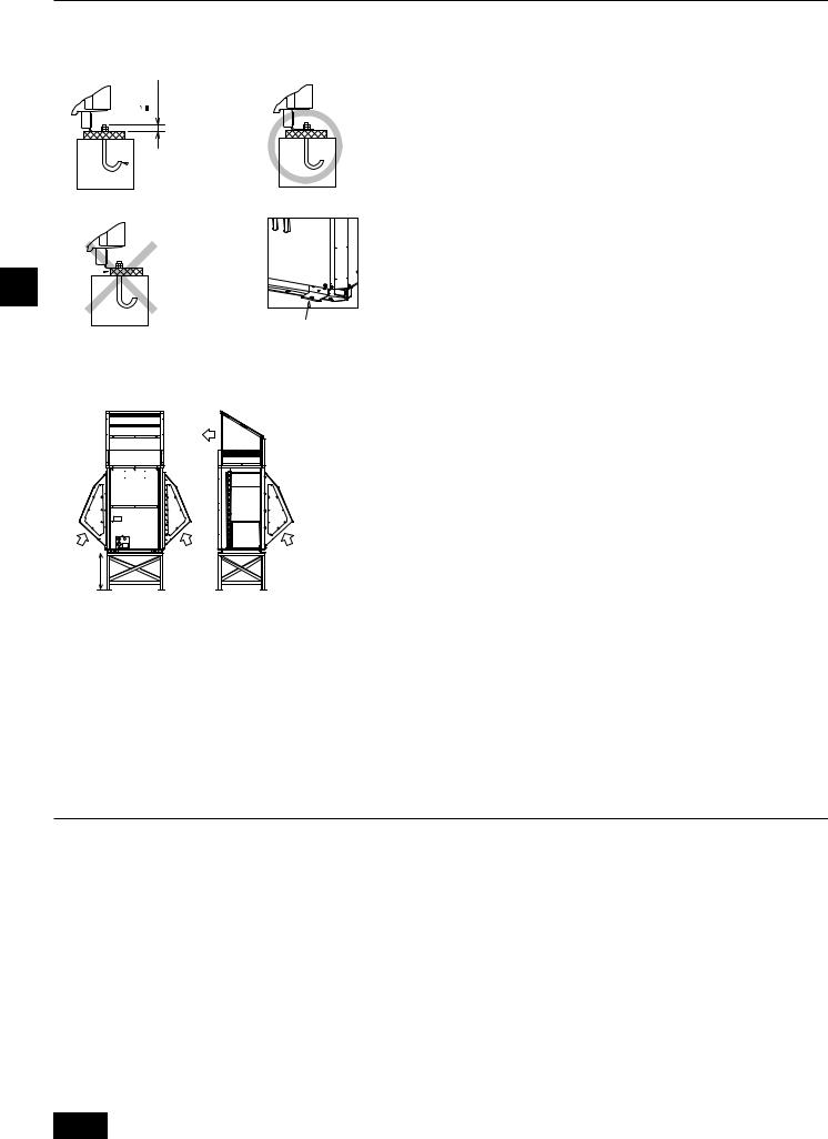
<A> Make sure the pipes from the twinning pipe to the outdoor unit are sloped downwards (towards the twinning pipes).
A  C
C  C
C
F B F
<B> When the piping on the outdoor unit side (from the twinning pipe) exceeds 2 m [6 ft], ensure a trap (gas pipe only) within 2 m [6 ft]. Make sure the height of the trap is 200 mm [7-7/8 in] or more.
If there is no trap, oil can accumulate inside the pipe, causing a shortage of oil and may damage the compressor.
(Unit: m [ft])
F |
D |
F |
|
||
C |
E |
C |
2[6] |
|
8
<C>Slope of twinning pipes
Make sure the slope of the twinning pipes are at an angle within ±15˚ to the ground.
If the slope exceeds the specified angle, the unit may be damaged.
F
±15°
G
<D>Pipe connection example
GB
H
I
H
J
A |
Downward slope |
B |
Upward slope |
C 1st branch |
D Trap (gas pipe only) |
E |
Within 2 m [6 ft] |
F |
Twinning pipe |
G Slope of the twinning pipes are at an angle within ±15˚ to the ground |
H |
Pipes on site |
|||
I |
Twinning Kit |
J |
Straight run of pipe that is 500 mm [19-11/16 in] or more |
|
|
|
|
10. Additional refrigerant charge
At the time of shipping, the outdoor unit is charged with refrigerant.
This charge does not include the amount needed for extended piping and additional charging of each refrigerant line will be required on site. In order that future servicing may be properly provided, always keep a record of the size and length of each refrigerant line and the amount of additional charge by writing it in the space provided on the outdoor unit.
10.1.Calculation of additional refrigerant charge
•Calculate the amount of additional charge based on the length of the piping extension and the size of the refrigerant line.
•Use the table below as a guide for calculating the amount of additional charging and then charge the system accordingly.
•If the calculation results in a fraction of less than 0.1 kg [4 oz], round up to the next 0.1 kg [4 oz]. For example, if the result of the calculation was 11.38 kg [402 oz], round the result up to 11.4 kg [404 oz].
<Additional Charge>
Additional |
|
Liquid pipe size |
refrigerant charge |
|
Total length of |
|
= |
ø19.05 mm [3/4"] |
(kg) [oz] |
|
(m) × 0.29 (kg/m) |
|
|
(ft) × 3.1 (oz/ft) |
|
|
|
|
|
|
|
|
|
|
|
Liquid pipe size |
+ |
Total length of |
|
ø9.52 mm [3/8"] |
||
|
|
|
|
|
(m) × 0.06 (kg/m) |
|
|
(ft) × 0.65 (oz/ft) |
|
|
|
Liquid pipe size Total length of
+ ø15.88 mm [5/8"]
(m) × 0.2 (kg/m) (ft) × 2.15 (oz/ft)
Liquid pipe size
Total length of
+ø6.35 mm [1/4"]
(m) × 0.024 (kg/m) (ft) × 0.26 (oz/ft)
Liquid pipe size Total length of
+ø12.7 mm [1/2"]
(m)× 0.12 (kg/m) (ft) × 1.29 (oz/ft)
+α
<Example> |
|
|
|
|
|
Indoor |
|
|
|
|
|
1: 48 A: ø12.7 mm [1/2"] |
40 m [131 ft] |
a: ø9.52 mm [3/8"] |
10 m [32 ft] |
|
|
2: 36 |
B: ø9.52 mm [3/8"] |
10 m [32 ft] |
b: ø9.52 mm [3/8"] |
5 m [16 ft] |
At the |
3: 15 |
C: ø9.52 mm [3/8"] |
15 m [49 ft] |
c: ø6.35 mm [1/4"] |
10 m [32 ft] |
conditions |
4: 12 |
D: ø9.52 mm [3/8"] |
10 m [32 ft] |
d: ø6.35 mm [1/4"] |
10 m [32 ft] |
below: |
5: 24 |
|
|
e: ø9.52 mm [3/8"] |
10 m [32 ft] |
|
The total length of each liquid line is as follows: ø12.7 mm [1/2"]: A = 40 m [131 ft] = 40 m [131 ft] ø9.52 mm [3/8"]: B + C + D + a + b + e
=10 m [32 ft] + 15 m [49 ft] + 10 m [32 ft] + 10 m [32 ft] + 5 m [16 ft] + 10 m [32 ft] = 60 m [193 ft]
ø6.35 mm [1/4"]: c + d = 10 m [32 ft] + 10 m [32 ft] = 20 m [64 ft] Therefore,
<Calculation example> Additional refrigerant charge
=40 m [131 ft] × 0.12 kg/m [1.29 oz/ft] + 60 m [193 ft] × 0.06 kg/m [0.65 oz/ft] + 20 m [64 ft] × 0.024 kg/m [0.26 oz/ft] + 3.5 kg [124 oz] = 12.4 kg [435 oz]
Value of α
Total capacity of connecting indoor units |
α |
|||
Models |
|
~ |
27 |
2.0 kg [71 oz] |
Models |
28 |
~ |
54 |
2.5 kg [89 oz] |
Models |
55 |
~ |
126 |
3.0 kg [106 oz] |
Models |
127 |
~ |
144 |
3.5 kg [124 oz] |
Models |
145 |
~ |
180 |
4.5 kg [160 oz] |
Models |
181 |
~ |
234 |
5.0 kg [177 oz] |
Models |
235 |
~ |
|
6.0 kg [212 oz] |
9

GB
10.2.Precautions concerning piping connection and valve operation
•Conduct piping connection and valve operation accurately.
•The gas side connecting pipe is assembled in the factory before shipment.
1For brazing to the connecting pipe with flange, remove the connecting pipe with flange from the valve, and braze it outside of the unit.
2The refrigerant circuit is closed with a round, close-packed packing upon shipment to prevent gas leak between flanges. As no operation can be done under this state, be sure to replace the packing with the hollow packing attached at the piping connection.
3At the mounting of the hollow packing, wipe off dust attached on the flange sheet surface and the packing. Coat refrigerating machine oil (Ester oil, ether oil or alkylbenzene [small amount]) onto both surfaces of the packing.
[Fig. 10.2.1]
C
A Close-packed packing
AB Hollow packing
D
C Valve
D Packing
E Connecting pipe with flange
 E
E
B
•After evacuation and refrigerant charge, ensure that the handle is fully open. If operating with the valve closed, abnormal pressure will be imparted to the highor low-pressure side of the refrigerant circuit, giving damage to the compressor, four-way valve, etc.
•Determine the amount of additional refrigerant charge by using the formula, and charge refrigerant additionally through the service port after completing piping connection work.
•After completing work, tighten the service port and cap securely so as not to generate any gas leakage.
•Flare machining dimension for systems using R410A is larger than that for systems using other types of refrigerant in order to increase the air tightness.
•Refer to the table on the below for flare machining dimensions, and follow the regulations set forth by the local authorities.
flare machining dimension (mm)
|
outer diameter |
size in inches |
dimension A |
|
R410A |
||
|
|
|
|
|
ø6.35 |
1/4" |
9.1 |
A |
ø9.52 |
3/8" |
13.2 |
|
ø12.7 |
1/2" |
16.6 |
|
ø15.88 |
5/8" |
19.7 |
|
ø19.05 |
3/4" |
24.0 |
flare nut size (mm) |
|
|
|
|
outer diameter |
size in inches |
dimension B |
|
R410A |
||
|
|
|
|
|
ø6.35 |
1/4" |
17.0 |
|
ø9.52 |
3/8" |
22.0 |
|
ø12.7 |
1/2" |
26.0 |
B |
ø15.88 |
5/8" |
29.0 |
|
ø19.05 |
3/4" |
36.0 |
[Fig. 10.2.2] |
|
|
|
<A> Valve |
<B> Valve |
|
<C> Valve |
gas side/ |
|
||
liquid side/ |
|
gas side/ |
|
(flanged type ) |
|
||
(flared type ) |
|
(flared type ) |
|
A |
|
|
|
|
|
D |
|
|
|
E |
|
|
|
|
C |
B |
|
|
|
|
|
|
J |
|
|
F |
|
C |
|
G |
|
H |
|
|
|
|
|
|
|
|
I |
|
|
AService port
For vacuuming in the refrigerant pipes on the site. (Tightening torque 12 N·m [120 kg·cm])
BShaft
Fully closed at the factory, when connecting the piping, and when vacuuming. Open fully after these operations are completed.
<When opening>
•Turn the shaft counterclockwise with a hexagonal wrench.
•Turn around the shaft until it stops.
<When closing>
•Turn the shaft clockwise with a hexagonal wrench.
•Turn around the shaft until it stops.
CFlare nut
Coat the flare contact surface with refrigerating machine oil (small amount of ester oil, ether oil, or alkyl benzene) and tighten the nut with a double-ended wrench (refer to the following table for tightening torque).
DCap
Remove the cap before operating the shaft. Be sure to return it to the original position after completing the operation.
EPacking
Coat both sides of the packing with machine refrigerating oil (small amount of ester oil, ether oil, or alkyl benzene) and tighten the flange.
(Tightening torque 25 N·m [250 kg·cm])
FConnecting pipe (accessory)
Be sure to remove the connecting pipe from the valve and braze it outside the unit.
GField piping
Braze to the connecting pipe with unoxidized brazing.
Hø9.52 mm [3/8"] (PUHY-HP72, HP96, when combining PUHY-HP72, HP96) ø12.7 mm [1/2"] (PUHY-HP72, HP96)
Iø22.2 mm [7/8"] (PUHY-HP96)
Jø19.05 mm [3/4"] (PUHY-HP72)
Appropriate tightening torque:
Outer diameter of |
Cap (N·m /kg·cm) |
Shaft (N·m /kg·cm) |
Size of hexagonal |
copper pipe (mm [in]) |
wrench (mm) |
||
ø9.52 [3/8] |
22/220 |
5/50 |
4 |
ø12.7 [1/2] |
20/200 |
9/90 |
4 |
ø15.88 [5/8] |
25/250 |
15/150 |
6 |
ø19.05 [3/4] |
25/250 |
15/150 |
6 |
ø25.4 [1] |
40/400 |
30/300 |
10 |
Appropriate tightening torque and its angle: |
|
||
|
|
|
|
Outer diameter of |
Tightening torque |
Tightening angle |
|
copper pipe (mm [in]) |
(N·m/kg·cm) |
(°) |
|
ø9.52 [3/8] |
35 - 42/350 - 420 |
60 to 90 |
|
ø12.7 [1/2] |
50 - 57.5/500 - 575 |
30 to 60 |
|
ø15.88 [5/8] |
75 - 80/750 - 800 |
|
|
|
|
||
ø19.05 [3/4] |
100 - 140/1000 - 1400 |
20 to 35 |
|
 Warning:
When connecting a pipe to the service valve, be sure to use only the supplied open-end flare nut, with small holes cut into the flats.
*Using a regular flare nut (i.e., non-supplied) will result in any water that naturally flows into the nut being unable to escape.
Consequently, when the temperature becomes low, this water inside the nut may freeze and cause damage to the joint. This, in turn, may result in a gas leakage.
[Fig. 10.2.3]
Note:
If a torque wrench is not available, use the following method as a standard; When you tighten the flare nut with a wrench, you will reach a point where the tightening torque will abruptly increase. Turn the flare nut beyond this point by the angle shown in the table above.
10
 Caution:
•Always remove the connecting pipe from the valve and braze it outside the unit.
- Brazing the connecting pipe while it is installed will heat the valve and cause
trouble or gas leakage. The piping, etc. inside the unit may also be burned.
•Use ester oil, ether oil or alkylbenzene (small amount) as the refrigerating machine oil to coat flares and flange connections.
-The refrigerating machine oil will degrade if it is mixed with a large amount of mineral oil.
•Keep the valve closed until refrigerant charging to the pipes to be added on site has been completed. Opening the valve before charging the refrigerant may result in unit damage.
•Do not use a leak detection additive. [Fig. 10.2.4]
AB
AExample of closure materials (field supply)
BFill the gap at the site
Make sure to seal-off and excess space around areas where the wires and refrigerant pipes enter the unit to ensure that small animals and rainwater cannot enter the unit through such openings and cause damage to the unit.
 Caution:
Make sure to seal-off and excess space around areas where the wires and refrigerant pipes enter the unit.
•Small animals and rainwater entering through the openings may cause damage to the device.
10.3. Airtight test, evacuation, and refrigerant charging
1Airtight test
Perform with the valve of the outdoor unit closed, and pressurize the connection piping and the indoor unit from the service port provided on the valve of the outdoor unit. (Always pressurize from both the liquid pipe and the gas pipe service ports.)
[Fig. 10.3.1]
|
|
|
F |
|
|
|
B |
G |
|
|
|
B |
H |
|
|
LO |
C |
I |
|
A |
HI |
|
||
D |
E |
J |
||
C |
||||
A Nitrogen gas |
B To indoor unit |
C System analyzer |
||
D Lo knob |
|
E Hi knob |
F Valve |
|
G Liquid pipe |
|
H Gas pipe |
I Outdoor unit |
|
JService port
Observe the following restrictions when conducting an air tightness test to prevent negative effects on the refrigerating machine oil. Also, with nonazeotropic refrigerant (R410A), gas leakage causes the composition to change and affects performance. Therefore, perform the airtightness test cautiously.
|
Airtight test procedure |
Restriction |
|
|
|
1. Nitrogen gas pressurization |
• If a flammable gas or air (oxygen) is used as the pressurization |
|
(1) |
After pressurizing to the design pressure (4.15 MPa [602 psi]) using nitrogen gas, allow it to |
gas, it may catch fire or explode. |
|
stand for about one day. If the pressure does not drop, airtightness is good. |
|
|
However, if the pressure drops, since the leaking point is unknown, the following bubble test |
|
|
may also be performed. |
|
(2) |
After the pressurization described above, spray the flare connection parts, brazed parts, flanges, |
|
|
and other parts that may leak with a bubbling agent (Kyuboflex, etc.) and visually check for |
|
|
bubbles. |
|
(3) |
After the airtight test, wipe off the bubbling agent. |
|
|
|
|
2. Pressurization using refrigeration gas and nitrogen gas |
• Do not use a refrigerant other than that indicated on the unit. |
|
(1) |
After first pressurizing with R410A liquid refrigerant to a gas pressure of approximately 0.2 |
• Sealing with gas from a cylinder will cause the composition of |
|
Mpa [29 psi], pressurize to the design pressure of 4.15 Mpa [602 psi] using nitrogen gas. |
the refrigerant in the cylinder to change. |
|
However, do not pressurize at one time. Stop during pressurization and check that the pres- |
• Use a pressure gauge, charging hose, and other parts especially |
|
sure does not drop. |
designed for use with R410A. |
(2) |
Check for gas leaks by checking the flare connection parts, brazed parts, flanges, and other |
• An electric leak detector for R22 cannot detect leaks of R410A. |
|
parts which may leak using an R410A compatible electric leak detector. |
• Do not use a haloid torch. (Leaks cannot be detected.) |
(3) |
This test may be used together the with bubble type gas leak test. |
|
|
|
|
 Caution:
Only use refrigerant R410A.
-The use of other refrigerant such as R22 or R407C, which contains chlorine, will deteriorate the refrigerating machine oil or cause the compressor to malfunction.
2Evacuation
Evacuate with the valve of the outdoor unit closed and evacuate both the connection piping and the indoor unit from the service port provided on the valve of the outdoor unit using a vacuum pump. (Always evacuate from the service port of both liquid pipe and gas pipe.) After the vacuum reaches 650 Pa [abs] [0.0943 psi/5 Torr], continue evacuation for at least one hour or more. Then, stop the vacuum pump and leave it for 1 hour. Ensure the degree of vacuum has not increased. (If the degree of vacuum increase is larger than 130 Pa
[0.01886 psi/1.0 Torr], water might have entered. Apply pressure to dry nitrogen gas up to 0.05 MPa [7.25 psi] and vacuum again.) Finally, seal in with the liquid refrigerant through the liquid pipe, and adjust the gas piping to obtain an appropriate amount of the refrigerant during operation.
*Never perform air purging using refrigerant.
[Fig. 10.3.2]
D
N 
 E
E
N |
|
F |
|
A |
|
O |
|
HI |
|
||
LO |
G |
||
B |
C |
||
|
|||
|
H |
I |
|
|
|
|
|
|
|
|
|
|
|
|
|
|
|
|
|
K |
||
|
|
|
|
|
|
|
J |
||
|
|
|
|
|
|
|
|||
|
|
|
|
|
|
|
L |
||
A System analyzer |
|
B Lo knob |
|||||||
D Valve |
|
E Liquid pipe |
|||||||
G Service port |
|
H Three-way joint |
|||||||
J Valve |
|
K R410A cylinder |
|||||||
M Vacuum pump |
|
N To indoor unit |
|||||||
M
CHi knob
FGas pipe
IValve
LScale
OOutdoor unit
GB
11
 Loading...