

Page 1

DC-6/DC-6T/DC-6Vet
Diagnostic Ultrasound System
Service Manual
Page 2

Page 3

CONTENTS
1 General Description .............................................................................. 1-1
1.1 System Characteristics ........................................................................................... 1-1
1.2 Applicable Scope .................................................................................................... 1-1
2 System Overview .................................................................................. 2-1
2.1 System Appearance ............................................................................................... 2-1
2.1.1 Complete System with CRT Monitor ........................................................................ 2-1
2.1.2 Complete System with LCD Monitor ........................................................................ 2-3
2.2 LCD Monitor ........................................................................................................... 2-4
2.2.1 Brightness and contrast buttons............................................................................... 2-5
2.2.2 Up/down adjusting lever ........................................................................................... 2-6
2.2.3 Lever of upper support arm ...................................................................................... 2-7
2.3 I/O Panel ................................................................................................................. 2-8
2.4 Power Panel ........................................................................................................... 2-9
2.5 ECG Panel............................................................................................................ 2-10
2.6 Control Panel ........................................................................................................ 2-11
2.6.1 Main panel .............................................................................................................. 2-11
2.6.2 Minor panel ............................................................................................................. 2-14
2.6.3 Keyboard ................................................................................................................ 2-15
2.7 Symbols ................................................................................................................ 2-18
3 Principle Description ............................................................................ 3-1
3.1 Electric Principle of the System .............................................................................. 3-1
3.2 Principle of Boards ................................................................................................. 3-2
3.2.1 Transducer Board ..................................................................................................... 3-2
3.2.2 Transmission board .................................................................................................. 3-3
3.2.3 Amplifier board ......................................................................................................... 3-3
3.2.4 Beamformer board ................................................................................................... 3-4
3.2.5 DSP board ................................................................................................................ 3-5
3.2.6 System motherboard ................................................................................................ 3-7
3.2.7 CW board ................................................................................................................. 3-8
3.2.8 Built-in PC module ................................................................................................... 3-9
3.2.9 IO module ............................................................................................................... 3-12
3.2.10 ECG module ......................................................................................................... 3-13
i
Page 4

3.2.11 Control panels and keyboard ............................................................................... 3-14
3.2.12 Detection board of Power Output ......................................................................... 3-15
3.2.13 CRT monitor ......................................................................................................... 3-16
3.2.14 LCD monitor ......................................................................................................... 3-17
3.3 Power Supply Principle ........................................................................................ 3-19
3.3.1 Power supply system ............................................................................................. 3-19
3.3.2 Principle of power boards ....................................................................................... 3-22
3.4 System Software .................................................................................................. 3-26
3.4.1 Structure ................................................................................................................. 3-26
3.4.2 Principle .................................................................................................................. 3-27
4 System Structure and Assembly/Disassembly .................................. 4-1
4.1 Exploded View of Complete System ...................................................................... 4-1
4.2 Exploded View of LCD Monitor and Support Arm .................................................. 4-3
4.3 Disassembly and Replacement .............................................................................. 4-4
4.3.1 Disassembly of the monitor ...................................................................................... 4-4
4.3.2 Replacement of the bottom light .............................................................................. 4-8
4.3.3 Replacement of spring damping parts ..................................................................... 4-9
4.3.4 Disassembly of the main panel .............................................................................. 4-14
4.3.5 Disassembly of the minor panel ............................................................................. 4-16
4.3.6 Replacement of the trackball .................................................................................. 4-18
4.3.7 Replacement of the main panel PCBA .................................................................. 4-19
4.3.8 Replacement of the keyboard PCBA ..................................................................... 4-22
4.3.9 Replacement of the keyboard ................................................................................ 4-23
4.3.10 Replacement of the light control PCBA ................................................................ 4-25
4.3.11 Replacement of the keyboard slide tracks ........................................................... 4-26
4.3.12 Replacement of the snap-close (lock head and lock seat) .................................. 4-27
4.3.13 Replacement of the travel switch (with the cable) ............................................... 4-29
4.3.14 Disassembly of the system boards ...................................................................... 4-30
4.3.15 Remove built-in PC module ................................................................................. 4-37
4.3.16 Remove HDD ....................................................................................................... 4-40
4.3.17 Remove the DVD-R/W assembly ......................................................................... 4-41
4.3.18 Remove the ECG assembly ................................................................................. 4-43
4.3.19 Remove the transducer board.............................................................................. 4-47
4.3.20 Replace the inlet dust net ..................................................................................... 4-49
4.3.21 Remove the transformer ...................................................................................... 4-51
ii
Page 5

4.3.22 Remove the fan assembly .................................................................................... 4-52
4.3.23 Replace casters ................................................................................................... 4-55
4.4 Installation of Peripherals ..................................................................................... 4-57
4.4.1 Installation of black/white video printer .................................................................. 4-57
4.4.2 Installation of color video printer ............................................................................ 4-59
4.4.3 Installation of VCR.................................................................................................. 4-63
5 Maintenance Requirements ................................................................. 5-1
5.1 Tools Required ....................................................................................................... 5-1
5.1.1 Tools/measurement devices and consumables ....................................................... 5-1
5.1.2 Standard configuration of tools and consumables ................................................... 5-2
5.2 Maintenance Personnel .......................................................................................... 5-3
6 Checks ................................................................................................... 6-1
6.1 Equipment condition Inspection ............................................................................. 6-1
6.1.1 Inspection Schedule ................................................................................................. 6-1
6.1.2 Checks before inspection ......................................................................................... 6-1
6.2 Function checks ..................................................................................................... 6-2
6.2.1 Flowchart for function checks................................................................................... 6-2
6.2.2 Content of the function checks ................................................................................. 6-2
6.3 Safety Checks ........................................................................................................ 6-4
6.3.1 Electric safety ........................................................................................................... 6-4
6.3.2 Checks for mechanical safety .................................................................................. 6-5
6.4 Image Checks ........................................................................................................ 6-8
6.4.1 B/W image phantom data checks and image records ............................................. 6-8
6.4.2 Check phantom data ................................................................................................ 6-8
6.4.3 Final operation checks and image archive ............................................................... 6-9
6.4.4 Checking color flow images ..................................................................................... 6-9
7 System Maintenance ............................................................................ 7-1
7.1 Cleaning ................................................................................................................. 7-1
7.1.1 Flowchart for cleaning .............................................................................................. 7-1
7.1.2 Content of the cleaning ............................................................................................ 7-1
7.2 Software Maintenance ............................................................................................ 7-4
7.2.1 Back up the preset data ........................................................................................... 7-4
7.2.2 Restore the preset data ............................................................................................ 7-5
7.2.3 Upgrade the software ............................................................................................... 7-7
7.2.4 System recovery .................................................................................................... 7-10
iii
Page 6

7.2.5 Hard disk recovery ................................................................................................. 7-12
7.2.6 Install and uninstall the software of optional devices ............................................. 7-13
7.2.7 Monitor test............................................................................................................. 7-15
7.2.8 Self-test .................................................................................................................. 7-17
8 Troubleshooting .................................................................................... 8-1
8.1 Troubleshooting for Power ..................................................................................... 8-1
8.2 Troubleshooting for Monitor ................................................................................... 8-1
8.3 Troubleshooting for the Power-up Process ............................................................ 8-2
8.4 Troubleshooting for the Operation Process............................................................ 8-3
8.5 Troubleshooting for Software ................................................................................. 8-3
8.6 Troubleshooting for Others ..................................................................................... 8-4
Appendix A Spare Part List ....................................................................... A-1
Appendix B Interface Definition and Function List ................................. B-1
Appendix C Initial Data of the Hard Disk .................................................. C-1
Appendix D Electrical Safety Inspection ................................................. D-1
iv
Page 7
© 2006-2012 Shenzhen Mindray Bio-Medical Electronics Co., Ltd. All rights Reserved.
For this Operator’s Manual, the issue date is 2012-09.
Intellectual Property Statement
SHENZHEN MINDRAY BIO-MEDICAL ELECTRONICS CO., LTD. (hereinafter called
Mindray) owns the intellectual property rights to this Mindray product and this manual.
This manual may refer to information protected by copyright or patents and does not
convey any license under the patent rights or copyright of Mindray, or of others.
Mindray intends to maintain the contents of this manual as confidential information.
Disclosure of the information in this manual in any manner whatsoever without the
written permission of Mindray is strictly forbidden.
Release, amendment, reproduction, distribution, rental, adaptation, translation or any
other derivative work of this manual in any manner whatsoever without the written
permission of Mindray is strictly forbidden.
,
WATO, BeneHeart, are the trademarks, registered or otherwise, of Mindray in
China and other countries. All other trademarks that appear in this manual are used
only for informational or editorial purposes. They are the property of their respective
owners.
, , , , BeneView,
Responsibility on the Manufacturer Party
Contents of this manual are subject to change without prior notice.
All information contained in this manual is believed to be correct. Mindray shall not be
liable for errors contained herein or for incidental or consequential damages in
connection with the furnishing, performance, or use of this manual.
Mindray is responsible for the effects on safety, reliability and performance of this
product, only if:
all installation operations, expansions, changes, modifications and repairs of this
product are conducted by Mindray authorized personnel;
the electrical installation of the relevant room complies with the applicable
national and local requirements; and
the product is used in accordance with the instructions for use.
Upon request, Mindray may provide, with compensation, necessary circuit diagrams,
calibration illustration list and other information to help qualified technician to maintain
and repair some parts, which Mindray may define as user serviceable.
Note
I-I
Page 8

This equipment is not intended for family usage.
This equipment must be operated by skilled/trained medical professionals.
Warning
It is important for the hospital or organization that employs this equipment to carry out a
reasonable service/maintenance plan. Neglect of this may result in machine breakdown
or injury of human health.
Warranty
THIS WARRANTY IS EXCLUSIVE AND IS IN LIEU OF ALL OTHER WARRANTIES,
EXPRESSED OR IMPLIED, INCLUDING WARRANTIES OF MERCHANTABILITY OR
FITNESS FOR ANY PARTICULAR PURPOSE.
Exemptions
Mindray's obligation or liability under this warranty does not include any transportation or
other charges or liability for direct, indirect or consequential damages or delay resulting
from the improper use or application of the product or the use of parts or accessories
not approved by Mindray or repairs by people other than Mindray authorized personnel.
This warranty shall not extend to:
Any Mindray product which has been subjected to misuse, negligence or accident;
Any Mindray product from which Mindray's original serial number tag or product
identification markings have been altered or removed;
Any product of any other manufacturer.
Safety, Reliability and Performance
Mindray is not responsible for the effects on safety, reliability and performance of the product
if:
Assembly operations, extensions, re-adjusts, modifications or repairs are carried out by
persons other than those authorized by Mindray.
Personnel unauthorized by Mindray repairs or modifies the instrument.
II
Page 9

Return Policy
Manufacturer:
Shenzhen Mindray
Bio-Medical Electronics Co., Ltd.
Address:
Tel:
Fax:
Return Procedure
In the event that it becomes necessary to return this product or part of this product to
Mindray, the following procedure should be followed:
1. Obtain return authorization: Contact the Mindray Service Department and obtain a
Customer Service Authorization (Mindray) number. The Mindray number must appear
on the outside of the shipping container. Returned shipments will not be accepted if the
Mindray number is not clearly visible. Please provide the model number, serial number,
and a brief description of the reason for return.
2.
Freight policy: The customer is responsible for freight charges when this product is
shipped to Mindray for service (this includes customs charges).
3. Return address: Please send the part(s) or equipment to the address offered by
Customer Service department
Company Contact
Mindray Building, Keji 12th Road South, Hi-tech Industrial Park,
Nanshan, ShenZhen 518057, P.R.China,
+86 755 26582479 26582888
+86 755 26582934 26582500
EC-Representative: Shanghai International Holding Corp. GmbH(Europe)
Address: Eiffestraβe 80, Hamburg 20537, Germany
Tel: 0049-40-2513175
Fax: 0049-40-255726
III
Page 10
Safety Precautions
1. Meaning of Signal Words
In this operator’s manual, the signal words DANGER, WARNING and NOTE are
used regarding safety and other important instructions. The signal words and their meanings
are defined as follows. Please understand their meaning before reading this manual.
Signal word Meaning
DANGER
WARNING
CAUTION
NOTE
Indicates an imminently hazardous situation that, if not avoided,
will result in death or serious injury.
Indicates a potentially hazardous situation that, if not avoided,
could result in death or serious injury.
Indicates a potentially hazardous situation which, if not avoided,
may result in minor or moderate injury.
Indicates a potentially hazardous situation that, if not avoided, may
result in property damage.
2. Meaning of Safety Symbols
Symbols Description
Type-BF applied part
The ultrasound transducers connected to this system are Type-BF applied
parts.
"Attention" indicates the points that you should pay attention to. Be sure to
read the operator’s manual concerning these points before using the
system.
IV
Page 11
3. Safety Precautions
Please observe the following precautions to ensure patient and operator safety when using
this system.
DANGER:
WARNING:
1. Do connect the plug of this equipment to the wall receptacle, and
2.... Be sure to connect the potential-equalization lead wire before
Do not use flammable gasses such as anesthetic gas, oxygen or
hydrogen, or flammable liquids such as ethanol, near this product,
because there is danger of explosion.
the plug must meet the ratings indicated on the rating nameplate.
Using an adapter or multi-functional receptacle may affect the
system grounding performance and thus causing the leakage
current to exceed safety requirements.
In addition, do connect the video printer to the auxiliary power
socket of this system. And use the printing cable provided by this
system to connect the printer. Otherwise, it may cause electric
shock.
inserting the equipment power plug into the receptacle. Also, be
sure to remove the equipment power plug from the receptacle
before disconnecting the wire to avoid electric shock.
3....Connect the earth conductor only before turning ON the system.
Disconnect the grounding cable only after turning OFF the system.
Otherwise, electric shock may result.
4.... For the connection of power and grounding, follow the appropriate
procedures described in this operation manual. Otherwise, there is
risk of electric shock. Do not connect the grounding cable to a gas
pipe or water pipe, otherwise functional grounding may not be
effective or there may be risk of a gas explosion.
5....Before cleaning the system, be sure to disconnect the power cable
from the outlet. If the system is defective, there is risk of electric
shock.
V
Page 12

6.... No waterproof device is applied to this equipment. Do not use this
equipment in any place with the possibility of water ingress. There
is risk of electric shock if any water is sprayed on or into the
equipment. If carelessly spray any water onto the equipment,
contact the Mindray sales office, customer service department or
representative.
7.... Use the transducer carefully. In case that the body contacts the
scratched transducer surface, immediately stop using the
transducer and contact the Mindray sales office, customer service
department or representative. There is risk of electric shock if using
the scratched transducer.
8.... Be careful not to let the patient contact the live parts of the
ultrasound equipment or other devices, such as signal I/O ports. If
the ultrasound equipment is defective, there is risk of electric
shock.
9. Do not use the transducers other than those specified by Mindray.
Otherwise, the equipment and the transducer may be damaged,
causing an accident such as a fire in the worst case.
10.
Do not subject the transducers to knocks. Use of defective
transducers may cause an electric shock.
11. Do not open the shell or front panel. If you open the shell when the
system is powered on, there may be a short circuit or electric
shock.
12. Do not use this system with using equipment at the same time such
as an electrosurgical unit, high-frequency therapy equipment, or a
defibrillator, etc. otherwise it may result in electric shock to the
patient.
13. Use only the ECG leads provided with the ECG module, otherwise it
may result in electric shock.
14. If this system needs to be moved, please hold the handle. If other
parts of the system are held, it may cause damage due to the
abnormal force. Do not push the system from the left/right side;
otherwise it may be toppled over.
VI
Page 13
15. Accessory equipment connected to the analogue and digital
interfaces must be complied with the relevant IEC standards (e.g.,
IEC 60950 Safety of information technology Equipment Standard
and IEC 60601-1 Medical Equipment standard). Furthermore all
configurations should comply with the standard IEC60601-1-1. Any
person, who connects additional equipment to the signal input or
output ports and configures a medical system, is responsible for
ensuring that the system complies with the requirements of
IEC60601-1-1. If you have any problem, consult the technical
services department of your local representative.
16. Prolonged and repeated use of keyboards can result in hand or
arm nerve disorders for some individuals. Observe the local safety
or health regulations concerning the keyboard use.
CAUTION:
(1) This system must be used only by qualified professionals.
(2) This operation manual does not describe clinical
2....Malfunctions due to radiowaves:
(1) Use of radiowave-emitting devices in the proximity of this
(2) If a person brings a device that generates radio waves near
3.... Precautions concerning installation and movement of the system:
(1) Ensure to install the equipment horizontally and lock up the
1....Precautions concerning clinical examination techniques:
examination techniques. Selection of the proper clinical
examination technique must be based on specialized
training and clinical experience.
medical electronic system may interfere with its operation.
Do not bring or use devices that generate radio waves, such
as cellular telephones, transceivers, and radio controlled
toys, in the room where the system is installed.
the system, ask him/her to immediately turn OFF the device.
casters securely. Otherwise, it may move to cause injury.
(2) Do not move the equipment from its sides; otherwise it may
be toppled over and may injure people.
(3) When you move the equipment on a slope, it shall be moved
slowly by two people; otherwise it may happen to slide and
severely injure people.
(4) Do not sit on the equipment, because it may move and make
people lose balance and fall.
VII
Page 14

(5) Dot not place any object on the monitor, because it may fall
and injure people.
(6) Fasten the peripheral devices before moving the equipment.
Otherwise, the peripheral devices may fall and injure people.
(7) When moving the equipment on steps, you shall prevent it
from being toppled.
4....Do not vibrate the equipment excessively (when moving the
equipment); otherwise the mechanical parts (such as casters) may
be damaged. If the equipment is often moved on a bumpy floor,
contact the Mindray sales office, customer service department or
representative.
5. Do not connect this system to outlets with the same circuit breakers
and fuses that control the current of devices such as life-support
systems. If this system malfunctions and generates an
overcurrent, or when there is an instantaneous current at power ON,
the circuit breakers and fuses of the building’s supply circuit may
be tripped.
6....Always keep the machine dry. Avoid transporting this machine
quickly from the cold place to the warm place; otherwise
condensation or water drops may be formed, causing short circuit.
7....If the circuit breaker is tripped, it indicates that the machine or the
peripheral devices have problems. In these cases, you cannot repair
by yourself but should contact the Mindray sales office, customer
service department or representative.
8.... There is no risk of high-temperature burns during routine
ultrasound examinations, even if, due to environment temperature
and exam modes, the surface temperature of the transducer exceeds
the body temperature of the patient. To prevent high-temperature
burns, do not apply the transducer to the same region on the patient
for a long time. Apply the transducer only for as long as required
time for diagnosis.
9....This device and its accessories are not disinfected and sterilized
when they are out of the factory, so the user shall disinfect and
sterilize transducers or biopsy brackets as per the manuals prior to
use of transducers or biopsy brackets. After the sterilization or
disinfection of accessories, chemicals must be washed out or gases
must be discharged thoroughly from the accessories. Remaining
residual chemicals or gases will not only result in damage to the
accessories but also can be harmful to human bodies.
VIII
Page 15
10....Before examining a new patient, press the key to delete
the patient information and data recorded in the image memory for
the previous patient. Otherwise, the new data may be confused
with the data of the previous patient.
11. Do not connect/disconnect the system and its accessories (such as
printers or DVD recorder) without turning OFF the power; otherwise
it may cause damage of the equipment or electric shock.
12. Do not turn OFF the power supply of the system during printing,
saving, or invoking; otherwise these processes may not be
completed normally or files may be lost.
13. During operation, if the system is improperly powered off, it may
result in data damage of the hard disk or system failure.
IX
Page 16

NOTE: 1. Do not use the machine in the vicinity of strong electromagnetic field (such
as the transformer), which may affect the performance of the machine.
2. Do not use the machine in the vicinity of high-frequency radiation source,
which may affect the performance of the machine or even lead to failure.
3. To avoid damaging the machine, do not use the machine in following
environment:
(1) Locations exposed to direct sunlight;
(2) Locations subject to sudden changes in temperature;
(3) Dusty locations;
(4) Locations subject to vibration;
(5) Locations near heat generators;
(6) Locations with high humidity.
4. Turn ON the system only after the power has been OFF for more than 20
seconds. If the system is turned ON immediately after being turned OFF,
the system may malfunction.
5. Turn OFF the auxiliary power switch or stop transmission through the
『Freeze』 key before connecting or disconnecting a transducer. If a
transducer is connected or disconnected with an image displayed, the
system and/or the transducer may malfunction.
X
Page 17

6. After using the transducer, remove the ultrasound gel on it and place the
transducer on the transducer holder. Otherwise, water in the gel may enter
the acoustic lens, thus adversely affecting the performance and safety of the
transducer.
7. You can record the registration data (including the hospital data and patient
data). To ensure the security of the data, be sure to back up the data on
external storage media. Data stored in the equipment may be lost due to
improper operation or an accident.
8. Do not apply external force to the control panel (e.g. leaning against it).
Otherwise it may damage the system.
9. If the system is used in a small room, the room temperature may rise.
Therefore, proper ventilation shall be provided.
10. When disposing the system or any part of it, contact your Mindray
representative. Do not dispose of this system without consulting Mindray.
Mindray would bear no responsibility for damages resulting from disposal of
this system without consulting Mindray.
11. Degradation of electrical and mechanical safety characteristics (such as
generation of a leakage current or deformation/abrasion of mechanical
parts) and of image sensitivity and resolution may occur after a period of
time. To ensure normal operation of the system, it is recommended to sign a
maintenance and service agreement to prevent accidents.
12. Output power outlet in the system is used to supply power for the
recommended peripheral devices. Do not connect other devices to the
outlet, otherwise the rated output power may be exceeded and failure may
result. Maximum output power of the power outlet for peripheral devices is
350VA.
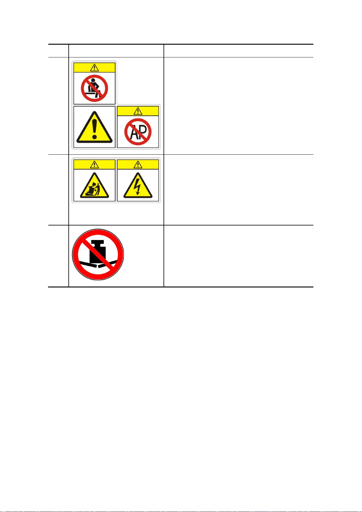
4. Warning Labels
Various warning labels are attached to this system in order to call the user's attention to
potential hazards.
The symbol
on the warning labels indicates safety precautions. The warning labels
use the same signal words as those used in the operation manual.
Detailed information about the warning labels is given in the operation manual. Read
operation manual carefully before using the system.
The name, pattern and the meaning of each warning label are described as follows:
XI
Page 18
No.
<1>
<2>
Label Meaning
(a) CAUTION: Do not sit on the system.
(b) Before using the system, be sure to carefully
read the relevant content of this operation
manual.
(c) DANGER: The system must not be used around
flammable gasses.
(a) CAUTION: Do not place the system on a sloped
surface. Otherwise the system may slide
unexpectedly, resulting in person injury or the
system malfunction. The system should be
moved over a sloped surface by two persons to
ensure safety.
(b) CAUTION: The system shells must not be
opened, because the high voltage inside may
cause electric shock.
<3>
Beware of excessive stress exerted to the system.
XII
Page 19

1
1.1
The DC-6/DC-6T/DC-6Vet Diagnostic Ultrasound System is a color Doppler system with
features of all-digital architecture and whole-body application, which is designed based on
clinical needs. The system supports a wide range of transducers, and its imaging modes
include B Mode, M mode, Pulsed Wave Doppler (PW), Continuous Wave Doppler (CW), Color,
and Power, Smart3D, iScape and Free Xros M. It supports single-frame files such as formats
of DICOM, BMP and JPEG, and Cine files such as CIN and AVI; the silicone keyboard and
flexible trackball are adopted for the system; the high-performance ICs are used to realize the
front-end transmission and reception and back-end software functions; the system is suitable
for a wide variety of hospitals and clinics.
1.2
System Characteristics
Applicable Scope
General Description
The DC-6/DC-6T Diagnostic Ultrasound System is applicable for adults, pregnant women,
pediatric patients and neonates, and it is intended for use in abdominal, cardiac, small parts
(breast, testes, thyroid, etc.), peripheral vascular, fetal, transrectal, transvaginal, pediatric,
neonatal cephalic, musculoskeletal (general and superficial), and intraoperative (liver,
gallbladder, pancreas) exams.
The DC-6Vet Diagnostic Ultrasound System is intended for use in abdominal, cardiac,
obstetric, small parts, peripheral vascular, transrectal, musculoskeletal (general and
superficial), and intraoperative exams for animals, such as dog, cat, equine, bovine and ovine,
etc.
1-1
Page 20
2
2.1
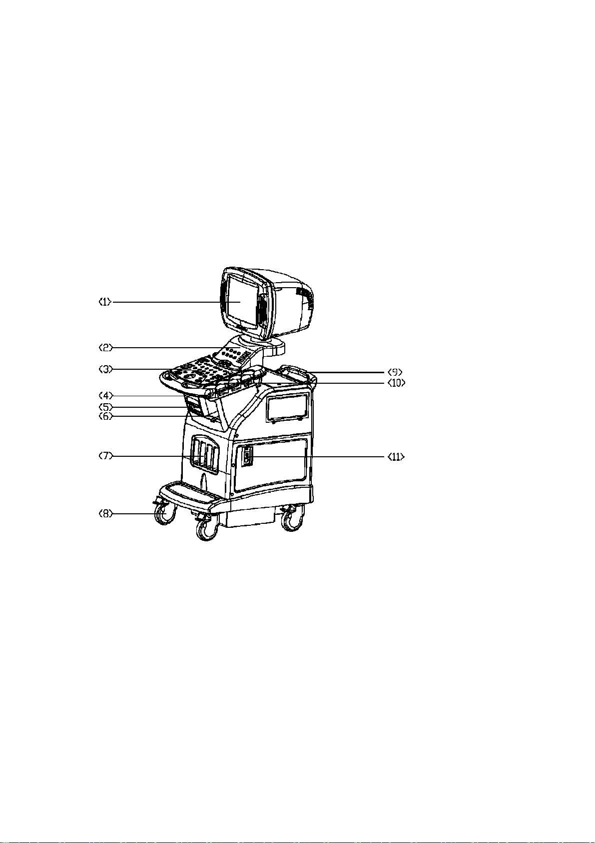
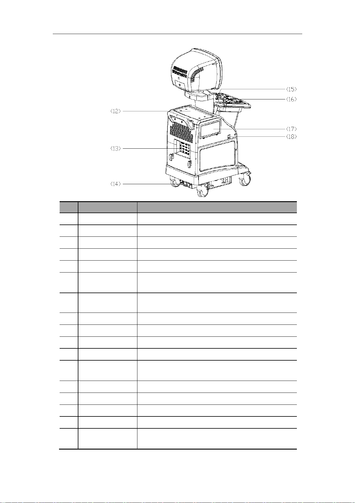
2.1.1 Complete System with CRT Monitor
System Appearance
System Overview
2-1
Page 21
System Overview
No
Name Function
<1> Monitor Displays the images and parameters during scanning
<2> Minor panel Human-machine interface, operation control
<3> Main panel Human-machine interface, operation control
<4> Keyboard Human-machine interface, operation control
<5> DVD-R/W Rewritable CD drive
<6> Space for placing
Used for placing B/W video printer
video printer
<7> Transducer socket Interface connecting transducers and the main unit
There are 3 active sockets and one dummy socket
<8> Casters Used for fixing or moving the system
<9> Handle Used for pushing the system
<10> Transducer holder Used for placing transducers temporarily
<11> ECG panel Used for connecting the ECG cable and footswitch, etc.
<12> Table for placing
Used for placing color video printer
color printer
<13> I/O panel Interface panel for input and output signals
<14> Power panel Electrical interface panel
<15> USB interface Used for USB devices
<16> MIC interface Used for connecting a microphone
<17> Space for placing
Used for placing VCR
VCR
2-2
Page 22
<18> Power switch Used for turning on/off the power supply
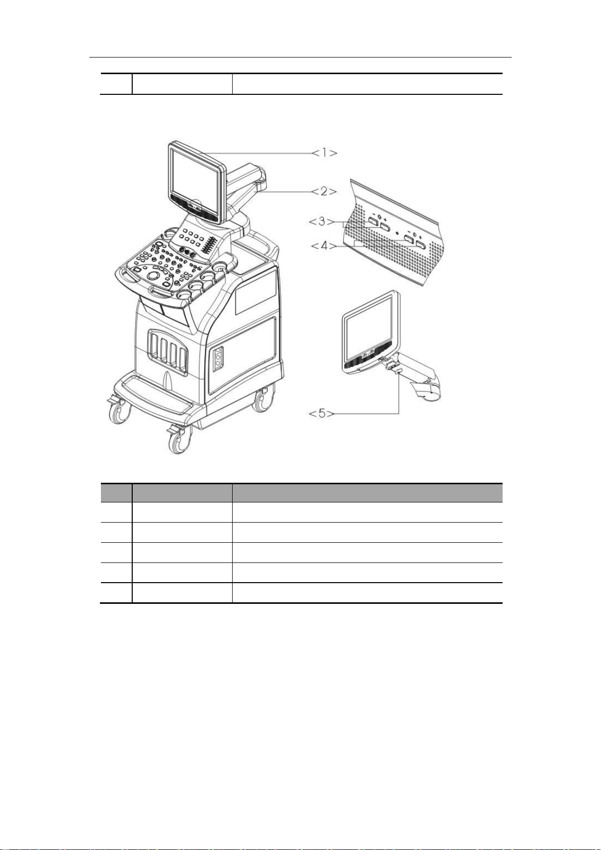
2.1.2 Complete System with LCD Monitor
System Overview
No
<1> Monitor Displays the images and parameters during scanning
<2> Monitor support arm Supports and adjusts height and position of LCD monitor
<3> Brightness buttons Adjust brightness of LCD monitor
<4> Contrast buttons Adjust contrast of LCD monitor
<5> Locking lever Locks the monitor in the lowest status
Name Function
2-3
Page 23
System Overview
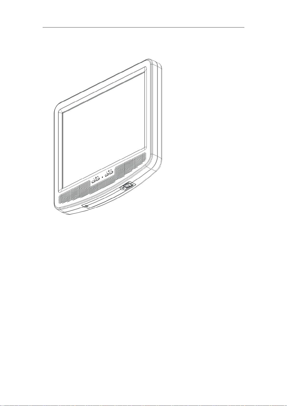
2.2
LCD Monitor
2-4
Page 24
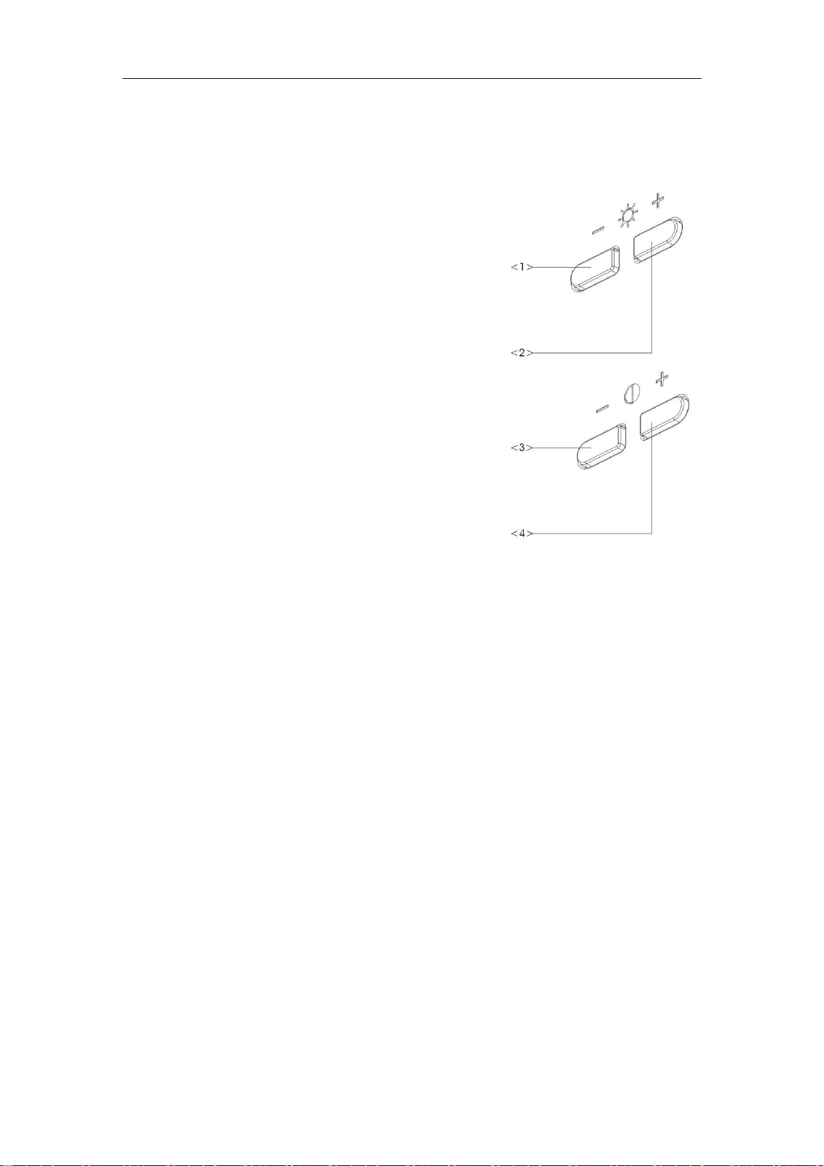
2.2.1 Brightness and contrast buttons
In the figure at the right side, 1> and <2> are
brightness-adjusting buttons, above which is a
sun symbol. A “-” symbol above the <1>
button indicates the button is used to
decrease brightness. A “+” symbol above the
<2> button indicates the button is used to
increase brightness.
<3> and <4> are contrast-adjusting
buttons, above which is a lune symbol. A “-”
symbol above the <3> button indicates the
System Overview
button is used to decrease contrast. A “+”
symbol above the <4> button indicates the
button is used to increase contrast.
Press both <2> and <3> buttons at the same time and hold for more than 3s, the default
brightness and contrast settings will be recovered.
Press both <1> and <4> buttons and hold for more than 3s to pop up the service menu of the
monitor, select “zoom select” to choose the image size to display; the default value is “user”.
NOTE: <1> and <2> are used to move the cursor up and down; <3> is used as “cancel” and
<4> is used as “OK”.
2-5
Page 25
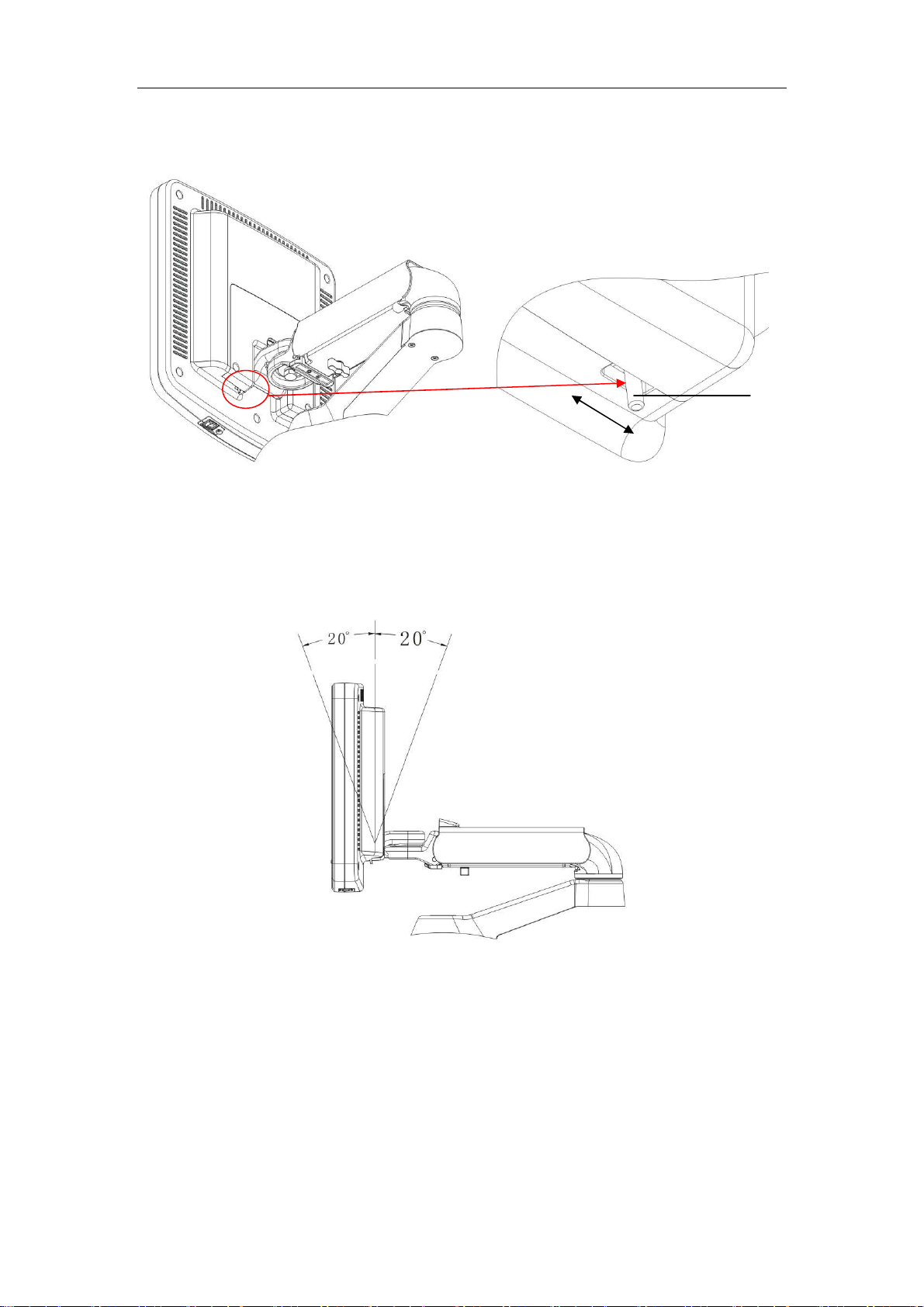
2.2.2 Up/down adjusting lever
System Overview
left
right
As shown in the figure above, the lever is located at the lower left of the monitor back. Only
when the lever is placed in the rightmost position can it be used for up/down adjustment of the
monitor. (Note: if there is no lever for another type of monitor, you can adjust it directly.)
The monitor can be tilted 20 degrees downward or upward. See the figure below.
lever
When the system is packed for transportation or moved to another place, push the lever to the
left side and push down the monitor so that the monitor is placed in the horizontal position.
See the figure below.
2-6
Page 26
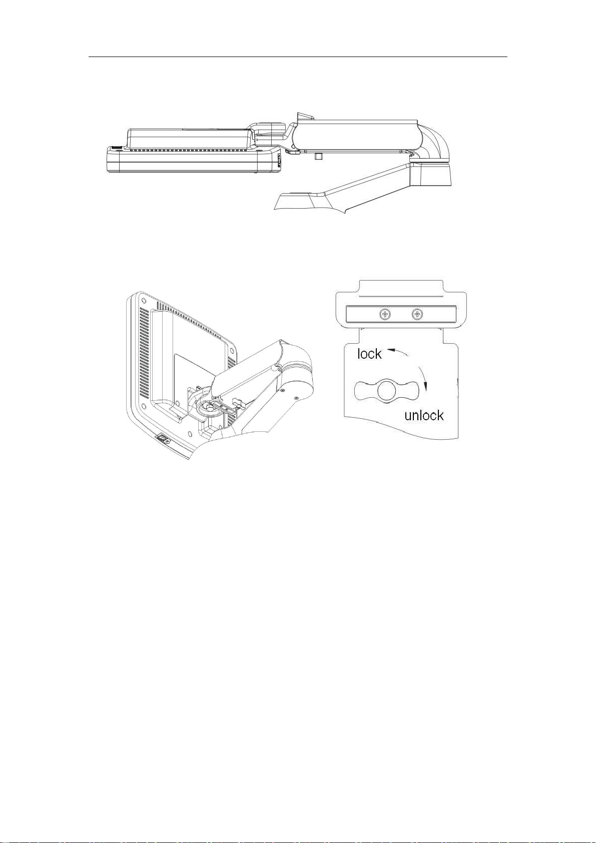
2.2.3 Lever of upper support arm
System Overview
2-7
Page 27
System Overview
>
>
9>
16>
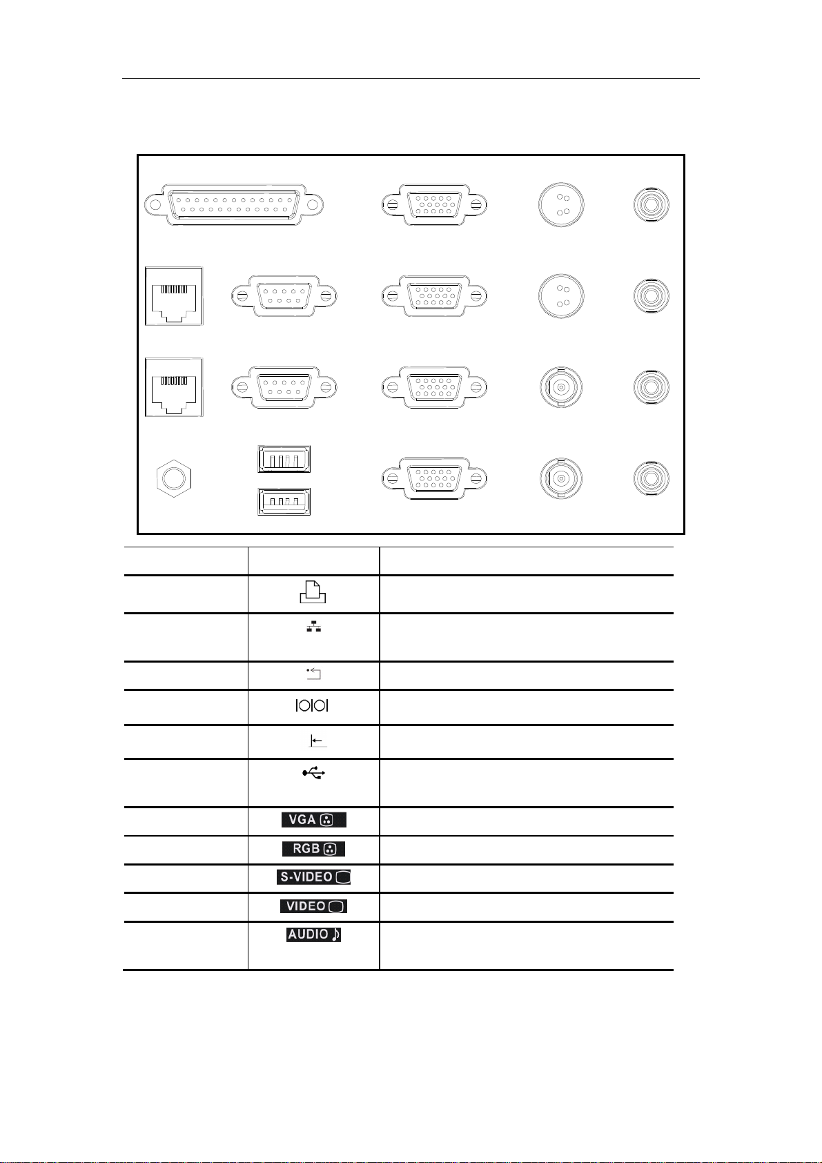
2.3
I/O Panel
<2>
<3>
<4>
<1> <9>
<5> <10> <14
<6> <11>
<7>
<8>
<12>
<13> <17
<18>
<15> <1
<
<20>
No Symbol Function
<1>
Used for system recovery
<2>, <3>
Ethernet interface (<2> is reserved for future
use; <3> can be used now.)
<4>
<5>
<6>
<7>, <8>
Control port for color video printer
USB port (<8> is used for USB devices, while
System reset
Serial port
<7> is for expansion.)
<9>,<10>
<11>,<12>
<13>,<14>
<15>,<16>
Used for RGB component video I/O
Used for VGA I/O
Used for separate video I/O
Used for composite video I/O
<17>,<18>
<19>,<20>
2-8
Used for stereo audio I/O
Page 28
System Overview
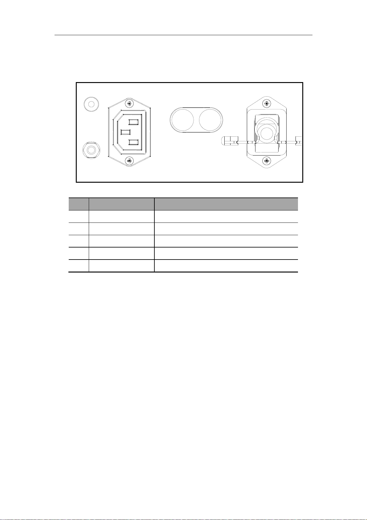
2.4
Power Panel
<1> <3>
<4>
<2>
No Name Function
<1> Ground terminal Used for grounding connection
<2> Equipotential terminal Used for equipotential connection
<5>
<3> Power outlet Power supply for optional peripheral devices
<4> Circuit breaker Used for cutting off power supply of the system
<5> Power inlet AC power inlet
2-9
Page 29
System Overview
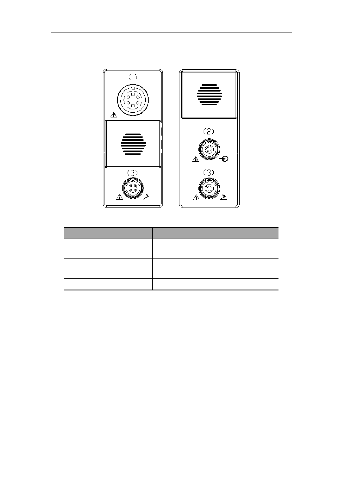
2.5
ECG Panel
No Name Function
<1> ECG lead signal input
interface
<2> External ECG signal
input port
<3> Footswitch interface Used for connecting the footswitch
Used for connecting ECG leads and acquiring
ECG signals
Used for connecting the signal output port of
ECG monitor
2-10
Page 30
System Overview
2.6
Control Panel
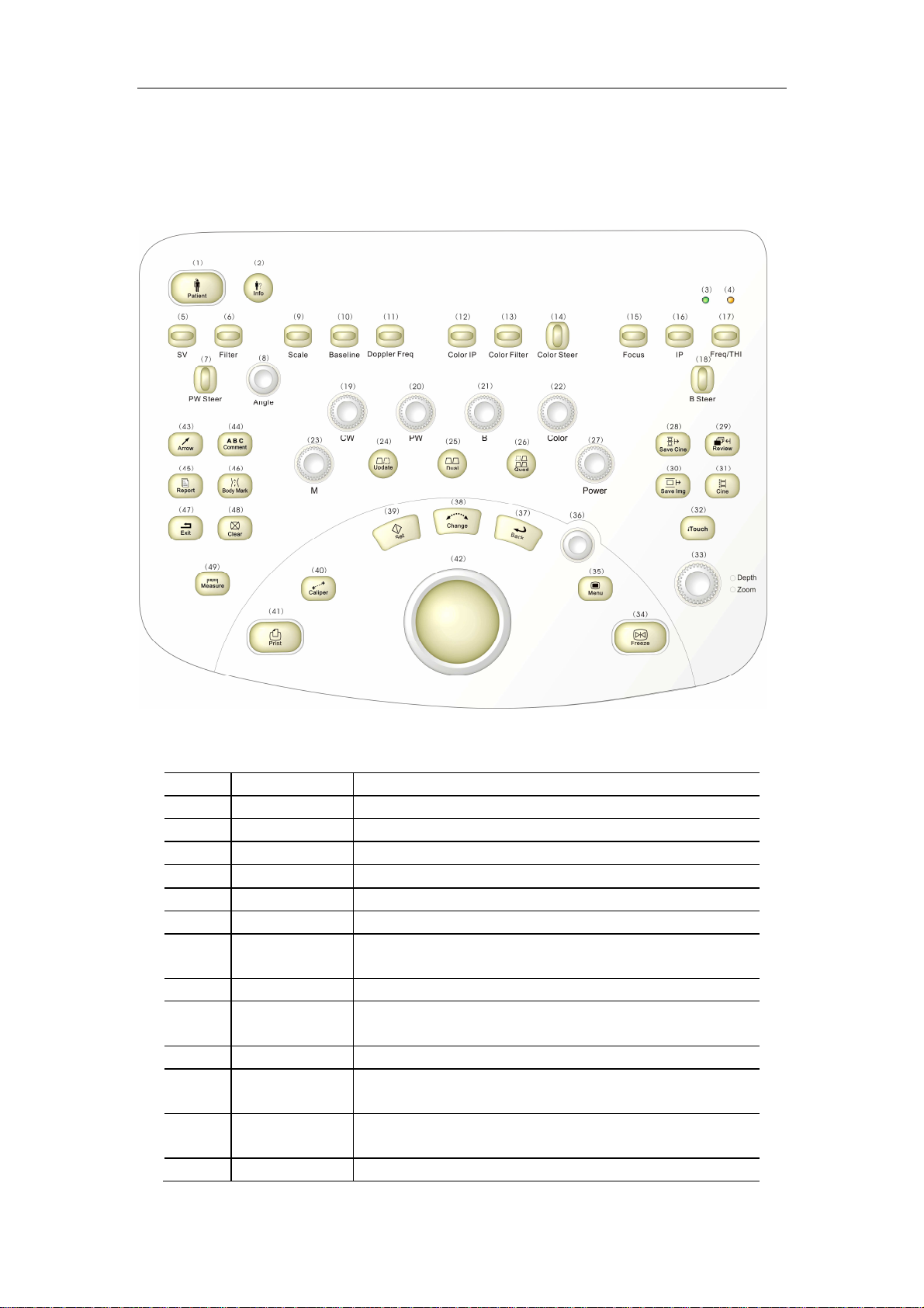
2.6.1 Main panel
No English Name
<1> Patient Press to start an exam of a new patient.
<2> Info Press to enter the patient information input screen.
<3> / Power indicator
<4> /
<5> SV Toggle to adjust the size of sample volume.
<6> Filter Toggle to adjust wall filter frequency in the PW mode.
<7> PW Steer Toggle to adjust SV steering angle of a linear transducer
<8> Angle Toggle to adjust SV corrected angle in the PW mode.
<9> Scale Toggle to adjust pulse repetition frequency in the
<10> Baseline Toggle to adjust baseline position in the PW/Color mode.
<11> Doppler Freq Toggle to adjust transmit frequency in the
<12> Color IP Toggle to select IP parameter combinations in the
<13> Color Filter Toggle to select wall filter in the Color/Power mode.
Hard disk indicator
in the PW mode.
Color/Power/PW mode.
Color/Power/PW mode.
Color/Power mode.
Function
2-11
Page 31

System Overview
<14> Color Steer Toggle to adjust ROI steering angle of a linear transducer
in the Color/Power mode.
<15> Focus Toggle to adjust focus position for B images.
<16> IP Toggle to select IP for B images.
<17> Freq/THI Toggle to adjust the current transducer frequency and
harmonic frequency.
<18> B Steer Toggle to adjust steering scan of a linear transducer or
trapezoid imaging.
<19> CW Press to enter the CW mode; rotate to adjust gain of a
CW image.
<20> PW Press to enter the PW mode; rotate to adjust gain of a
PW image.
<21> B Press to enter the B mode; rotate to adjust gain.
<22> Color Press to enter the Color Doppler mode; rotate to adjust
gain.
<23> M Press to enter the M mode; rotate to adjust gain of an M
image.
<24> Update Press to switch between image windows in M/B mode,
PW/B or CW/B mode., Press to start or end image
capture in the 3D mode.
<25> Dual Enters dual-split screen display, or changes the live
image window in Dual.
<26> Quad Enters the quad-split screen display, or changes the live
image window in the Quad mode.
<27> Power Press to enter the Power Doppler mode; rotate to adjust
gain.
<28> Save Cine Quickly saves cine files to the default region of the
internal hard disk in the preset image format.
<29> Review Reviews the image files of the current patient or the last
patient.
<30> Save Img Quickly saves image files to the default region of the
internal hard disk in the preset image format.
<31> Cine Enters the cine review status.
<32> iTouch Press to optimize images.
<33> Depth/Zoom When the Depth indicator lights on, the knob is used for
adjusting image depth by turning it; when the knob is
pressed down and the Zoom indicator lights on, the knob
is used for adjusting magnification factor by turning it.
<34> Freeze Freezes or unfreezes an image.
<35> Menu Invokes or closes the menu corresponding to the current
status.
<36>
Multifunction knob: it functions differently depending upon
different statuses. Refer to the relevant sections for
specific functions.
<37> Back Returns to the previous operation.
<38> Change Changes the active point of the caliper during
measurement; or opens the comment library in the
comment status.
2-12
Page 32

<39> Set Confirms an operation, equivalent to the left-button of the
mouse.
<40> Caliper Starts general measurement function.
<41> Print Prints the screen image (video print control).
<42> Trackball Adjusts the cursor’s position on the screen.
<43> Arrow Adds comment arrows, and the arrow orientation is
adjusted through the multifunction knob.
<44> Comment Press to start the comment function and the system
enters the comment status.
<45> Report Enters the current patient report.
<46> Body Mark Enters the body mark status.
<47> Exit Exits the current status.
<48> Clear Clears all comments, measurement calipers,
and the selected body marks on an image.
<49> Measure Starts application measurement functions.
System Overview
2-13
Page 33

2.6.2 Minor panel
System Overview
No English Name Function
<1> / Reserved for future use, can be defined
<2> / Reserved for future use, can be defined
<3> / Reserved for future use, can be defined
<4> / Reserved for future use, can be defined
<5> Record Used for data recording, can be defined
<6> ECG Entering or exiting the ECG menu
<7> iStation Entering the patient files management
<8> Probe Switching between effective transducers connected
and its exam mode.
<9> TGC Adjusting time gain compensation
<10> A.Power Adjusting Acoustic Output
<11> ECG Adjusting ECG signal position and ECG gain
<12> Volume Adjusting Doppler sound volume
2-14
Page 34

2.6.3 Keyboard
Ejection of the keyboard
System Overview
Push the edge of the keyboard inward slightly, and then the keyboard automatically ejects
outward. At this time the light under the main control panel is bright automatically to lighten
the keyboard.
Retraction of the keyboard
Push the keyboard inward, and when a click sound is heard, the keyboard is retracted.
2-15
Page 35

Functions of the keys
No Key Function
System Overview
<1> Enter
<2> Esc
<3> Tab Jumping to the next operation
<4> Space Inserting a space
<5> Caps Lock Switching between upper and lower case letters
<6> Num Lock Switching between numeric and other characters
<7> Shift
<8> Ctrl
<9> Alt Combined key
<10> Pause/Break /
<11> Home
<12> End
<13> PgUp Turning pages upward or leftward
<14> PgDn Turning pages downward or rightward
<15> Arrow Moving the cursor position
<16> Ins Switching between insertion and overwrite
<17> Del Deleting characters after the cursor
<18> Back Space Deleting characters before the cursor
<19> PrtSc /
<20> Win Logo /
<21> Application /
Receiving the input data; or moving the cursor to the head of
next row of the text or the input field.
Same as that of the『Exit』key
Press the『Shift』key and another key simultaneously, and then
upper and lower case letters or upper and lower characters can
be switched; Shift+ +Set;
Combined shortcut, Ctrl+ +Set;
Moving the cursor to the head of the row, or the leftmost side of
an edit unit.
Moving the cursor to the tail of the row, or the rightmost side of
an edit unit.
NOTE: ”/” symbols represent the keys are undefined.
2-16
Page 36

Functions of the keys F1 to F12
Quickly starting the patient information screen (identical to the
Quickly starting the diagnosis report screen (identical to the
ment status (identical to the
No Key Function
<1> F1 /
<2> F2
『Info』 key)
<3> F3
『Report』 key)
<4> F4 Quickly starting the com
『Comment』 key)
<5> F5 /
<6> F6 /
<7> F7 /
<8> F8 /
<9> F9 Switching to the video replay menu
System Overview
<10> F10 Quickly starting preset function
<11> F11 Turning on/off the display of biopsy guide line
<12> F12 /
NOTE: for the keys undefined, the user can define functions for them as per needs and habit.
Refer to the “Preset” chapter for details.
2-17
Page 37

System Overview
2.7
explained as well. Refer to “Safety Precautions” for safety symbols.
Symbols
This system uses the symbols listed in the following table, and their meanings are
Symbol Meaning
!
Type-BF device
Refer to relevant content in the Operation Manual, to avoid
safety accidents
Dangerous voltage
AC (alternate current)
Functional earth
Equipotentiality
Protective earth
Breaker ON/OFF
Power ON/OFF
Footswitch
Transducer socket
Network port
Parallel port
Serial port
S-VIDEO signal interface
VIDEO signal interface
VGA signal
RGB signal
External signal input
Remote control port
USB
2-18
Page 38

System Overview
System reset
Audio signal
Microphone input jack
Product serial number
Manufacture date
Manufacturer
2-19
Page 39

3
3.1
Electric Principle of the System
Principle Description
The system consists of transducer module, transmission module, reception module, CW
module, beamformer module, B/M-mode signal processing module, color flow signal
processing module, Doppler signal processing module, DSC module, CPU system, ECG
module, and input/output module, etc.
Transducer
board
Transducer
interface
board
POUT
Scan control
signal
Data bus
Transmission
Connector
board
CW board
Scan control
Amplifier
board
ECHO
Front-end FPGA
configuration bus
signal
Front-end control bus
Beamformer
B , M
C, CM
PW, CW
DSP
board
IO connecting
board
Hardwired
Hardwired
IO
board
LED board
Fan
isolation
transformer
Power
external
power
input
PHV1
A+5V
-PHV1
A-100V
PHV2
A+100V
-PHV2
A+5V
A-5V
A+12V
D+3.3V
D+5V
D-12V
Fan connecting
board
connecting
board
external
adapter board
auxiliary
output
A+5V
A-5V
D+3.3V
A+12V
PHV1
-PHV1
D+5V
system motherboard
PFC board +5V board
auxiliary
output
peripheral output
A+5V
A-5V
Power output detecting board
Power motherboard
D+5V
D+3.3V
-5V board
D+5V
D+3.3V
D+12V
A-5V
A+5V
HDD
PHV board
3-1
Page 40

Principle Description
3.2
Principle of Boards
3.2.1 Transducer Board
The block diagram of the transducer board is shown as follows:
Relay-EN2
Relay-EN1
Relay-EN0
Relay-EN3
The transducer board is designed for switching between the transducers and recognition of
the transducer IDs. The transducer switching signal controls the relays to switch between
the transducers, and the ID reading circuit is independent of the transducer switching circuit
and can read out the IDs of the transducers.
For A, B, C, and D transducers, the channel, double-pole double-throw relays are respectively
adopted to control the status of the transducer. Now take relay drive of the transducer A as an
example to describe the principle of the transducer switching. After the transducer select
control signal D_Relay-ENA is driven by 245, the four-channel signal D_Relay-ENA is
obtained. The four-channel signals are respectively driven by four relays to generate the
eight-channel signals A The A signals respectively control channel relays, so that the element
of the transducer A can be selected.
The transducer ID codes are selected by the signal CS and read into CPLD. After the system
reads out a transducer’s ID code, the system software will set the D_Relay-ENX (X
3-2
Page 41

Principle Description
represents A, B or C) signal to select the corresponding transducer. Since the system may
read multiple transducer ID codes simultaneously, the system software will select the
corresponding transducer based on the current exam.
When transducers are disconnected or connected, the interrupt signal will be automatically
generated to notify the system software, so that the system software can obtain the current
status of transducer connection and provide the prompt message accordingly.
3.2.2 Transmission board
The block diagram of the transmission board is shown as follows:
The transmission board is designed for generation of high-voltage pulse and transmission
sequence. The transmission circuit consists of two parts: transmission sequence and
transmission drive. The transmission sequence circuit generates low-voltage transmission
pulse, which passes the transmission drive circuit and is converted to high-voltage pulse. The
transmission board is provided with four programmable transmission voltages by the power
supply, so that the board can generate different transmission waveforms depending on the
needs of the system.
3.2.3 Amplifier board
The block diagram of the amplifier board is shown as follows:
The amplifier board is designed for voltage-controlled gain amplification of small signal echo.
3-3
Page 42

Principle Description
The amplifier board consists of high-voltage isolation circuit, channel select circuit, primary
voltage-controlled gain amplification circuit and secondary fixed gain amplification circuit. The
control signal of the channel select logic is derived from the beamformer board, and this
signal controls the on-off of the reception channel. The primary gain amplification circuit
consists of AD8332 and the peripheral circuits. The AD8332 is a dual-channel
voltage-controlled gain amplifier, and the gain voltage is derived from DA conversion from the
beamformer board and ranges between 0.04V and 1V. The secondary fixed gain amplification
circuit consists of AD8132 and the peripheral circuits.
3.2.4 Beamformer board
The block diagram of the beamformer board is shown as follows:
The beamformer board consists of beamformer module, signal processing FPGA module, and
signal processing DSP module. The beamformer board is designed for AD sampling,
beamforming, radio frequency signal processing, Doppler signal processing, flow signal
processing, video signal processing, and generation of scan control signal, etc.
The channel difference analog signal, transmitted from the system motherboard, passes the
low-pass filter to avoid aliasing of subsequent AD sampling. The cut-off frequency is 15 MHz.
After the signal is filtered and passes 8 pieces of high-speed AD for sampling, the sampled
data is sent to FPGA U46 and U65 for beamforming.
The data, after beamforming, is sent to FPGA U4 for B/W signal processing.
3-4
Page 43

Principle Description
At the same time the data is sent to FPGA U59 for color flow signal processing and partial
Doppler signal processing. Subsequently part of data is sent to FPGAU83 for remaining color
flow signal processing, and the other part of the data is sent to DSP U78 for remaining
Doppler signal processing. Then the B/W signal, color flow signal, Doppler signal pass the
system motherboard and are sent to the DSP board for the subsequent processing.
3.2.5 DSP board
The DSP board consists of Cine module (Cine), digital scan conversion module (DSC),
back-end display module (Display), and data capture module (Capture) and CPU system. Its
block diagram is shown as follows:
The Cine, DSC, 3D data capture and back-end display modules are designed for post
processing, and the FPGA is adopted for these functions.
The MCF5474 is used as the system CPU, to control the modules and whole system.
The functions of the modules are described as follows:
3.2.5.1
Pre-processing of echo data
Cineloop storage and review in each mode
DDR internal memory used for Cineloop storage
The Cine and DSC modules both have 4 parallel data channels for 2-D image, M image,
Doppler image and ECG waveform.
3.2.5.2
The DSC module is designed for conversion from echo data format to VGA data format.
3.2.5.3
The up USB interface is used for transferring original image data to the PC platform.
Cine module
DSC module
Capture module
The down USB interface is used for storage of 3D data calculated by the PC in the RAM.
3-5
Page 44

The USB interface HDD can be realized.
Connector
Description
Status
Remarks
Connector
Description
Connector
Description
Principle Description
3.2.5.4
Processing of graphic and image integration and provision of control interface for main
The graphic memory is directly accessed by CPU.
Interface control of video input and output
3.2.5.5
The CPU system is the control core of the ultrasound system, consisting of hardware
Communicating with other MCU or DSP, and configuring, initializing, and monitoring each
Initialization configuration for system FPGA and DSP;
System control: parameter control for FPGA; management for system controllers; on-line
Display module
CPU to graphic memory
CPU system
system and software system. The hardware provides support for functions of the system
software, and the software realizes the control of hardware modules. The functions of the
CPU system include: image display and measurements, and human-machine interaction.
hardware module;
upgrading of each MCU.
3.2.5.6
J1 USB IDE HDD interface Not supported
J2 Reserved FPGA serial port Not welded
J4 Reserved 1561 USB Host port Not supported
J6 CPU BDM and JTAG select
J7 Small HDD socket Not supported Either HDD socket or CF
J10 JTAG link of PLD Supported For JTAG configuration of
J11 JTAG link of CPU and PLD Not supported
J14 USB Device interface of CPU Not supported
J15 BDM socket interface of CPU Supported For CPU system debugging
J166 CF card socket Not supported
JP1-4 Used for connecting CPU’s
Connectors of the DSP board
jumper
JTAG link and PLD’s JTAG
link
No jumper for
BDM
Not supported
socket is welded
CPLD and FPGA
and program downloading
3.2.5.7
D1 3.3V power indicator D27 FPGA configuration
Functions of LED indicators
indicator
3-6
Page 45

Principle Description
ISP1161 test output
D2 5V power indicator D30
indicator
D7 -5V power indicator D31-D34 Connection indicator of
network control
D8,D14,D15 FPGA debugging indicator D37,D39-D41 DSC FPGA debugging
indicator
D9,D10,D25 ISP1561 USBVBUS
indicator
D11,D18,D36 Cine FPGA debugging
indicator
D12 DSC FPGA configuration
indicator
D13 12V power indicator D49 Capture FPGA
D17, D26 CPU debugging indicator D50-D51 CPLD debugging status
D19-D24 ISP1561 status indicator
D38 Cine FPGA configuration
status indicator
D42-D44 ISP1583 Suspending
status indicator
D45-D48 Capture FPGA debugging
status indicator
configuration status
indicator
indicator
3.2.6 System motherboard
The system motherboard, serving as platform of the hardware system, provides power
channels and signal channels for modules.
The IO signal connection diagram of the system motherboard is shown as follows:
3-7
Page 46

Principle Description
Category
Interface
Socket
Use
I/O interface definition of the system motherboard:
number
Interfaces with
boards
Transducer
connecting board
ECG module Soft-wired 1 2 serial ports
PC module Hard-wired
USB, microphone Soft-wired 3 3 USB (one reserved), 1 microphone
Footswitch signal Soft-wired 1 To ECG board
Power control
signal
Power signal Hard-wired
Hard-wired
Hard-wired
Hard-wired
5 Connecting transmission board, amplifier
board, beamformer board, DSP board, and
the board reserved
1 Transducer signal
power signal
footswitch
Powered by power supply
1 1 serial port
3 USB ports
S-Video signal
Status signal and PC power signal
Powered by power supply
interface
1 1 serial port, for power control
SW, SW-EN soft switch signal, PW-OFF
4 For each channel of power
3.2.7 CW board
The CW board diagram is shown below, which consists of four portions: transmission,
reception, power and control.
3-8
Page 47

Principle Description
eception
Reception
Tissue
3.2.7.1
Transmit
converter
R
converter
Transmit
amp
RF amp
Transmit
beamformer
Waveform
generator
Quadrat
ure
demo
beamform
Transmission
The transmission signal flow graph is shown as follows:
er
filter
Audio
amp
Result
display
Signal
process
AD
convert
er
3.2.7.2
The high voltage isolation circuit is used to protect the reception circuit. Although a relay is
placed in the front-end of the reception circuit to isolate from the transducer, if fault occurs for
the relay control, the high voltage may be applied to the front-end of the reception circuit.
Therefore the high voltage isolation is necessary.
The band pass filter is used to filter extremely low frequency component and sum frequency
component in the signal demodulated. It consists of two-level active high-pass filter and
four-level active low-pass filter.
Reception
The reception signal flow graph is shown as follows:
3.2.8 Built-in PC module
3.2.8.1
The built-in PC module is used for background processing of 3D and iScape data. The image
data is transferred from ultrasound system to PC system via a USB2.0 interface, for the
System function
3-9
Page 48

Principle Description
purpose of analysis, such as 3D imaging. In the figure below, the broken line stands for
control flow, while the real lines stand for data streams. The main CPU control
communicates with the built-in PC via a serial port. The built-in PC initiates USB2.0 main
control of the PC system and USB2.0 slave of the ultrasound system. The data is transferred
via USB2.0, and the main CPU system determines that the results are to be displayed
whether by the ultrasound system or by the built-in PC.
Data before DSC processing
main CPU
control
USB2.0 for data transfer
Graph/image Circuit
Image capture
MonitorMoSwitchS
Built-in PC
3.2.8.2
PC carry board
The industrial control PC has advantages in the aspects of reliability, signal interface methods,
power supply categories, and power consumption, so it is used as the built-in PC. The built-in
PC module consists of PC carry board, industrial control board, memory stick, HDD and fan.
The PC carry board is introduced as follows:
The data transfer between the PC carry board and the digital processing board is completed
via 2-channel USB2.0 interface;
The PC carry board communicates with the digital processing board 5474 via a serial port;
The S-VIDEO interface is used for maintaining mode display;
The USB and kilomega Ethernet interface is used for connecting the IO-BOX;
HDD supporting SATA interface is used to store 3D system data;
CPLD is used to manage the system power system;
The PC carry board obtains power of 12V, 5V or 3.3V from the mother board;
The PC carry board interfaces are shown as follows:
3-10
Page 49

Principle Description
3.2.8.3
The ZPACK110 socket is used for connecting the PC carry board and mother board, and
signals are defined as follows:
Interface definition
3-11
Page 50

Principle Description
PA SIG.DES
PB
SIG.DES
PC
SIG.DES
PD
SIG.DES
PE
SIG.DES
Model: 110Pin PC platform
PA.1 GND PB.1 DM-SIG PC.1 DP-SIG PD.1 GND PE.1 VBUS-SIG
PA.2 GND PB.2 DM-PC2 PC.2 DP-PC2 PD.2 GND PE.2 VBUS-PC2
PA.3 VBUS-PC1 PB.3 DM-PC1 PC.3 DP-PC1 PD.3 GND PE.3 GND
PA.4 PC-YIN PB.4 PC-CIN PC.4 GND PD.4 GND PE.4 GND
PA.5 PW-STS PB.5 BOARD-DETECT PC.5 NC PD.5 NC PE.5 NC
PA.6 GND PB.6 GND PC.6 GND PD.6 GND PE.6 GND
PA.7 RXD-PC PB.7 TXD-PC PC.7 PS-DATA PD.7 PS-CLK PE.7 /
PA.8 GND PB.8 GND PC.8 GND PD.8 GND PE.8 GND
PA.9 GND PB.9 GND PC.9 GND PD.9 GND PE.9 GND
PA.10
PA.11
PA.12
PA.13
PA.14
PA.15
PA.16
PA.17
PA.18
PA.19
PA.20
PA.21
PA.22
D+5 PB.10
D+5 PB.11
D+5 PB.12
GND PB.13
GND PB.14
D+3.3 PB.15
D+3.3 PB.16
GND PB.17
A-5 PB.18
GND PB.19
GND PB.20
D+12 PB.21
D+12 PB.22
D+5 PC.10
D+5 PC.11
D+5 PC.12
GND PC.13
GND PC.14
D+3.3 PC.15 D+3.3 PD.15 D+3.3 PE.15
D+3.3 PC.16 D+3.3 PD.16 D+3.3 PE.16
GND PC.17
A-5 PC.18
GND PC.19
GND PC.20
D+12 PC.21 D+12 PD.21 D+12 PE.21
D+12 PC.22 D+12 PD.22 D+12 PE.22
D+5 PD.10
D+5 PD.11
D+5 PD.12
GND PD.13 GND PE.13
GND PD.14 GND PE.14
GND PD.17 GND PE.17
A-5 PD.18
GND PD.19 GND PE.19
GND PD.20 GND PE.20
D+5 PE.10
D+5 PE.11
D+5 PE.12
A-5 PE.18
D+5
D+5
D+5
GND
GND
D+3.3
D+3.3
GND
A-5
GND
GND
D+12
D+12
Interfaces between the PC carry board and IOBOX: 1 USB port, 1 network port.
3.2.9 IO module
The IO module consists of IO connecting board, IO adapter board, and IO interface board.
The connection relation between these boards is shown as follows:
1. One end of the IO connecting board is connected to the DSP board, and the other end is
connected to the IO adapter board; the standard 40PIN IDE HDD interface and 4PIN
power interface are provided, and the power socket for HDD cooling fan is reserved.
2. One end of the IO adapter board is connected to the IO connecting board, and the other
end is connected to the IO interface board; the adapter board serves as an extension
board.
3. The IO interface board is connected to the IO adapter board, and provides IO interfaces
and the power of the system; the IO interfaces are divided into internal IO (invisible for
the user) and external IO (visible for the user).
The block diagram of the IO module is shown as follows:
3-12
Page 51

Principle Description
DSP
board
IO connecting board
Hard-wired
Hard-wired
Hard-wired
HDD
IO adapter board
IO interface board
PARALLEL
COM 1
ETHERNET 1/2
USB 1/2
VGA OUT 1
REMOTE 1
RGB OUT 1
S-VIDEO OUT 1
VIDEO OUT
AUDIO OUT 1
RGB IN
VIDEO IN 1
S-VIDEO IN 1
AUDIO IN 1
RESET
VGA IN
TO DVD RW (S-VIDEO IN, S-VIDEO OUT,
AUDIO IN, AUDIO OUT, SERIAL PORT)
TO CD-RW (IDE)
TO monitor (VGA, AUDIO-PW OUT)
TO VCR (S-VIDEO IN, S-VIDEO OUT,
AUDIO IN, AUDIO OUT, SERIAL PORT)
TO B/W VIDEO PRINTER (VIDEO OUT, REMOTE 1)
TO TOUCHSCREEN (SERIAL PORT, VGA)
LCD
LCD
KEYBOARD
CD RW
Note: other modules are in the broken lines
DVD
TOUCHSCREEN
3.2.10 ECG module
The ECG module is designed for monitoring of ECG signals and display of ECG waveforms,
which serve as reference of ultrasound images. The ECG module can synchronously trigger
display of 2-D images and color flow images. After the ECG signal is amplified, filtered and
sampled, through the RS232 serial port, the signal is sent to the DSC module; at the same
time the R-wave is detected, and the detected ECG-triggering signal is sent to the system
controllers through interrupt, to start the scan transmission. The ECG module communicates
with the main CPU system through the RS232 serial port.
The ECG signal can be inputted to the system, through an interface compatible with Mindray’s
monitoring products.
3-13
Page 52

Principle Description
ECG lead
DC IN
Footswitch
Front
interface
board
Amplifier
ECG module
Filter
Sampling
HR
detect
Main CPU system
DSC module
System
control
3.2.11 Control panels and keyboard
The control panels and keyboard are designed for key scanning, indicator control, buzzer
control, receiving and processing for encoder data, STC data, PS/2 data, and they
communicate with the main unit through serial ports. The control panels and keyboard consist
of main panel, minor panel, encoder panel, and light control board, etc. The block diagram is
shown as follows:
The block diagram of the main panel is shown as follows:
3-14
Page 53

Principle Description
enclosure
protective
earth
TGC
adjustment (8-
segment)
serial
comm
interface
5V/3.3V
DC/DC
converter
ATmega64L
RS232
serial
level
converter
LED drive/control
DC/DC
converter
74HC373
EPM570T144
rotary encoder
74HC14
buzzer
4 independent
keys
65-key matrix
rotary encoder
knob value
The keyboard plays an important role in information communication between the ultrasound
system and environment, and on the basis of functions it consists of: CPU circuit, DC/DC
conversion circuit, key control circuit, trackball control circuit, encoder control circuit, LED
drive circuit and STC A/D sampling circuit. The CPU circuit consists of one MCU chip and the
peripheral circuit, and it is the core of the keyboard, to process various types of information.
The DC/DC circuit is used to provide different levels required by the keyboard. The key
control circuit refers to the key processing hardware, which consists of CPLD and the
peripheral circuit. The trackball control circuit and encoder control circuit are used to convert
the external mechanical actions to signals which are recognizable by MCU, and the circuits
consist of trackball, encoder, waveform shaping circuit and hardware processing circuit. The
LED control circuit is used to indicate statuses of LEDs. The STC A/D sampling circuit
consists of sliding potentiometer, amplifier and AD sampling circuit, and it is used to convert
the analog signal from the sliding potentiometer to the digital signal which can be accepted by
MCU.
3.2.12 Detection board of Power Output
The detection board of power output is designed to precisely adjust the programmable
high-voltage and monitor other output voltage.
The programmable high-voltage is divided into PHV1, -PHV1, PHV2 and -PHV2, and the
adjustment ranges are between +5V and +80V and between -5V and -80V, and the
adjustment precision is 1%.
For other voltages, the digital voltages include: D+12V, D+5V, D+3.3V and D-12V; the analog
voltages include: A+100V, A-100V, A+12V, A+5V and A-5V.
3-15
Page 54

The block diagram of the detection board is shown as follows:
Principle Description
power
output
module
HPV1
-HPV1
HPV2
-HPV2
CON1
CON2
CON3
CON4
+D3P3V
+D5V
+A5V
-D12V
+D12V
voltage
divider
voltage
divider
voltage
divider
voltage
divider
ADT7516
voltage
divider
voltage
divider
voltage
divider
voltage
divider
voltage
divider
follow
backward
follow
backward
lowpass
lowpass
lowpass
backward
lowpass
lowpass
lowpass
lowpass
SPI
ADT7516_VREF
lowpass
lowpass
AD7928
SPI
+D5V
-A5V
POWER
VREF
clock
+5V
A5V
-A5V
Max6066
REF3040
232
voltage
divider
voltage
divider
backward
MAX3243
lowpass
lowpass
TTL
Atmega
64L
JTAG
SPI
download
interface
-A100V
+A100V
CONNECTOR
3.2.13 CRT monitor
The CRT monitor is used to convert electric signal, transmitted from the main board, to
high-speed electrons for impacting fluorescent screen, thus generating light signal to make
images seen on the screen. The external indicator of the CRT is designed to judge if the
monitor works normally. Generally if there is synchronous signal, this indicator is green;
otherwise it is yellow.
3-16
Page 55

3.2.14 LCD monitor
Principle Description
3.2.14.1
parts.
No Components Name Qty
1 15 inch TFT LCD PANEL-LQ150X1LW71N 1
2 15 inch LCD control board- LQ150X1LW71N 1
3 15 inch LCD LVDS connecting wire 1
4 Connecting wire between 15 inch LCD power board
5 15 inch LCD OSD board 1
6 15 inch LCD OSD connecting wire 1
7 15 inch LCD light board-12v 1
8 15 inch LCD power inverter board 1
9 15 inch LCD light switch and connecting wire 1
Components of LCD monitor module
LCD module consists of 15 inch LCD display screen, boards and cards, wires and metal
The components of the LCD module are shown as follows:
1
and drive board
10 LCD fixing bracket 1
11 Reinforced plate 1
12 Shielding mask bracket 1
13 Left plate of shielding mask 1
14 Right plate of shielding mask 1
15 LCD fixing bracket 1
16 Wire strip CHS-3X80mm nylon 2
17 Cross panhead screw GB/T9074.8 M3X8 coated with
rust-proof nickel
18 Aluminum sunk screwφ3.2*7(GB/T 12617) 21
The 15 inch LCD display screen is a specified model, LQ150X1LW71N made by SHARP;
the boards, cards and wires are customized according to structure and interface
specifications.
29
3-17
Page 56

Principle Description
3.2.14.2
CCFL
Function diagram
15" LCD panel
Audio L +/-
Inverter & Power LCD drive
12v
Speaker(right)Speaker(left)
Audio R +/-
LVDS
Signal , 12v
Key OSD board
12v
AC 90-260V VGA Audio L/R
Auxiliary output
AC 90-260V
3.2.14.3
Interface definition
Definition of LVDS signal output pins:
Drive voltage 3.3V, LVDS interface.
PIN SIGNAL PIN SIGNAL
1 VCC 11 RX2-
IO interface board
Light board
12v
Toggle
switch
12v
2 VCC 12 RX2+
3 GND 13 GND
4 GND 14 CK5 RX0- 15 CK+
6 RX0+ 16 GND
3-18
Page 57

7 GND 17 RX38 RX1- 18 RX3+
9 RX1+ 19 GND
10 GND 20 GND
Definition of speaker signal pins:
PIN NUMBER SIGNAL
1 L-SDBX+
2 L-SDBX3 R-SDBX+
4 R-SDBX-
Definition of VGA signal pins:
PIN NUMBER SIGNAL
Principle Description
1 VSYNC
2 GND
3 HSYNC
4 GND
5 RED
6 BLUE
7 GREEN
8 GND
9 GND
10 GND
Definition of AC input pins:
PIN NUMBER SIGNAL
1 L
2 N
3 GND
3.3
Power Supply Principle
3.3.1 Power supply system
The power system consists of connecting board, PFC board, +5V board, -5V board, PHV
3-19
Page 58

Principle Description
board, adapter board of auxiliary output, LED board, adapter board of fans, power
motherboard and detection board of power output.
The AC line power passes the circuit breaker to enter the connecting board, and then, through
the isolation transformer, two isolated outputs are obtained. After filtered, one output serves
as AC auxiliary output for the monitor and printers, the other passes the power motherboard
to become the input power for the PFC board. After entering the PFC board, the power is
converted to a stable 390V high-voltage DC output through the BOOST PFC, and then
provided for the +5V board and -5V board to finally output +5V, +3.3V, -5V, 12V and -12V. The
12V serves as the input power of the PHV board, and it passes the FLYBACK converter in the
PHV board to output ±100V voltages; four programmable voltages are obtained through the
BOOST converter and BUCK-BOOST converter.
After passing the power motherboard, the outputs of the power system are connected to the
detection board of power output for filtering and monitoring. After the programmable voltages
are detected, they are outputted to the main unit for supplying power for relevant hardware
circuits. The outputs of the power system, after passing the fan adapter board, are connected
to the LED board. The LED board indicates the statuses of the outputs.
3-20
Page 59

isolation
transformer
Principle Description
L
N
color video
printer
auxiliary
output adapter
board
B/W video
printer
monitor
VCR
DC+
DC-
VDD
DC+
DC-
FL
FN
Connecting
board
PFC board
PFC
PF
VPP
RY+
FL
FN
VPP
RY+
5B
SW
LED
POFF
ENA
GND
+5V
SW
5B
LED
POFF
ENA
GND
CON(1~4)
+5V board
+5V
VDD
+3.3V
+12V
Power
motherboard
+5V
+3.3V
LED indicator
LED
board
Fan
connecting
board
detection
board of
power
output
fan
SW
LED
POFF
ENA
GND
+5V
+3.3V
System
motherboard
-5V board
-5V
PHV
PHV
board
-12V
-5V
PFL
PFL
+12V
+/-HV
PHV(1~4)
CON(1~4)
+12V
-12V
-5V
+/-HV
PHV(1~4)
fan
connecting
board
A+12V
-12V
-5V
+/-HV
PHV(1~4)
fan
3-21
Page 60

3.3.2 Principle of power boards
Principle Description
3.3.2.1
The block diagram of the connecting board is shown as follows.
Connecting board
The line power input passes the circuit breaker to enter the connecting board, passes the
surge current rejection circuit to reach an isolation transformer, and then the isolation
transformer generates two AC outputs which are isolated with the line power. After passing
one-level or multiple-level EMI filter, one output provides power for the PFC board, and the
other, through relay control, provides power for the monitor and printer. The high and low
voltages of the line power are selected by tieline of the transformer. After the system is turned
on, the PFC boards sends the relay shut-off signal, and bypasses the thermistor rejecting
surge current, and the AC auxiliary output is switched on.
3.3.2.2
The PFC board consists of APFC power circuit, STANDBY power, control circuit of soft switch,
LED indicator circuit and protection circuit. The diagram is shown as follows.
The AC input power passes the EMI filter, and then passes the rectifier bridge to reach the
BOOST APFC power circuit. In the APFC control circuit, the APFC function of the input power
is completed, and a stable +390V DC current is outputted to the +5V board and -5V board.
The APFC control circuit is powered by the STANDBY power supply. The structure of the
PFC board
STANDBY is single-end FLYBACK converter. The STANDBY not only provides +18V power
VCC for the APFC control circuit, but also outputs an isolated +5V voltage for control circuit of
soft switch and LED control circuit.
3-22
Page 61

Principle Description
EMI
FILTER
APFC
CIRCUIT
DIODE
BRIDGE
CONTROL
390Vout
PWM
CONTROL
CIRCUIT
REGULATOR
ON/OFF
LOGIC
LED
CONTROL
CIRCUIT
REGULATOR
CIRCUIT
ON/OFF
CONTROL
CIRCUIT
DC+
VDD
LED
ENA
SW
RY+
PF
POFF
+5V
BOARD
Besides OVP and OTP, the PFC board receives the fail protection signal PF from the +5V
board, the soft turn-off signal POFF and turn-off enable signal ENA, thus realizing the safe
turn-off of the entire power system.
The core ICs of the PFC board, PFC controller and PWM controller, are respectively UC3854
and 38HC43 made by TI.
-5V BOARD
OVP/OTP
CIRCUIT
PHOTO
-
COUPLER
3.3.2.3
+5V board
The structure of the +5V board is single-end forward active-clamp conversion.
The DC input voltage passes a LC filter and is sent to a transformer, and then passes PWM
control and is converted to square-wave voltage. After the square-wave voltage passes a
rectification filter, the stable +5V DC voltage is outputted. The duty cycle of PWM controller is
adjusted by error-amplifying signal of feedback network and transmission of a photocoupler.
The +5V passes a BUCK converter to output the +3.3V, and the control IC of the BUCK
converter is LTC1629EG made by LINEAR. The control IC of the PWM is U9, i.e., UCC2894
made by TI, and the switching tube is 2KS2611 made by TOSHIBA.
3-23
Page 62

Principle Description
PFC
board
PF signal
Input
filter
Active
clamp
PWM
control
PF signal
circuit
FORWARD
converter
optocoupler
isolation
(feedback)
optocoupler
isolation
(feedback)
feedback
secondary
auxiliary power
supply
+5V/+3.3V
BUCK
converter
+5V/30A
output
+3.3V/30A
output
3.3.2.4
-5V board
The -5V board adopts the structure of single-end forward converter, and its block diagram is
shown as follows. The 390Vdc input enters the power board through the +5V board and a
connector, and it passes the LC filter to become the input of the FORWARD converter. After
passing the FORWARD converter, the DC voltage is converted to stable DC outputs of +12V,
-5V and -12V. The +12V is the main feedback output of the converter, the other two are
auxiliary outputs, and adjustment of magnetic amplifier is used as stabilizing method.
3-24
Page 63

+5V
power
board
390Vdc
input
filter
circuit
FORWARD
transformer
magamp
adjustment
1
ocp/ovp signal
rectifier
filter
overcurre
nt & over-
voltage
detection
Principle Description
-12V output
PFL signal
VDD
OTP
PWM
control
optocoupler
isolation
magamp
adjustment
2
rectifier
filter
rectifier
filter
feedback
-5V output
power
motherboard
+12V output
OVP&
OVP
3.3.2.5
PHV board
After the 12V input voltage enters the PHV, it passes the FLYBACK converter to generate two
groups of positive and negative high voltages. After the 12V input voltage passes the
BOOST converters and BUCK-BOOST converters, PHV1, PHV3, PHV2 and PHV4 are
outputted.
The control IC of the FLYBACK converter is UC3843 made by ONSEMI, and the main
switching tube is IRF3710 made by IR (100V/60A). The control IC o f the BOOST converter is
TL594 made by ONSEMI, and the switching tube is IRF52N15DPBF made by IR (150V/60A).
The control IC of the BUCK-BOOST converter is MAX1847 made by MAXIM, and the
switching tube is IRF6215PBF made by IR (150V/13A). The output voltage values have linear
relation with the programmable voltages. When the programmable voltages vary within the
range of 0 and 4V, the absolute values of the output voltages vary within the range of 5 and
80V.
3-25
Page 64

Principle Description
3.3.2.6
The principle of other boards is simple and all components on the boards are almost passive,
so it isn’t necessary to describe it.
3.4
Other boards
System Software
3.4.1 Structure
The system software consists of hardware interface layer, medium support layer and upper
software layer. The upper software is comprised of patient information management system,
measurement and calculation, image mode control, peripheral control and preset, etc.
3-26
Page 65

Principle Description
3.4.2 Principle
The entire software system runs through asynchronous processing mechanism of message
control. Commands are entered through GUI system and control panel, and stored in
mailboxes, so that the software system can obtain the commands from the mailboxes to
interpret and execute.
3-27
Page 66

4
System Structure and
Assembly/Disassembly
4.1
Exploded View of Complete System
4-1
Page 67

System Structure and Assembly/Disassembly
No Part Number
Name
No
Part Number
Name
1 2105-20-40185 monitor tail cover 17 2105-30-40252 DVD assembly
(optional)
2 2105-20-40184 monitor rear cover 18 2105-20-40159 VCR cover plate
3 2105-20-40198 Up/down pin roll 19 2105-30-40376 VCR assembly
(optional)
4 2105-30-40392 Monitor supporting
and moving
20 2105-20-40120 R1000 transformer
(1000VA)
assembly
5 2105-30-40389 Bottom light
21 2105-20-40238 Transformer partition
assembly
6 2105-30-40390 monitor front cover 22 2105-20-40170 Air inlet dust net
7 2105-21-85992 Monitor CRT
assembly
8 2105-30-40437 minor panel rear
cover assembly
9 2105-30-40386 minor panel
assembly
10 2105-30-40385 main panel
23 2105-30-40360 main unit paddle
assembly
24 2105-30-40359 main unit front cover
assembly
25 2105-30-40373 video printer
assembly (optional)
26 2105-30-40375 DVD-R/W assembly
assembly
11 2105-30-40388 keyboard support
assembly
27 2105-30-40370 System transducer
assembly
12 2105-30-40387 keyboard assembly 28 2105-30-40366 main unit housing
assembly
13 2105-30-40374 color printer
assembly
14 2105-30-40358 main unit rear
cover assembly
15 2105-30-40367 System main unit
box assembly
16 2105-30-40363 Power main unit
29 2105-30-40382 power input
assembly
30 2105-30-40361 main unit neck front
cover assembly
31 2105-30-40380/
2105-30-40489
ECG assembly
(Chinese/English)
32 2105-20-40164 DVD-R/W front cover
box assembly
4-2
Page 68

System Structure and Assembly/Disassembly
4.2
Exploded View of LCD Monitor and Support Arm
No Part Number Name No Part Number Name
1 2111-30-73327 Base assembly 9 6200-10-09762 Ground wire strip
2
2111-20-73283
3
2111-20-73313
4
M6T-020002---
5
2111-20-73296
6
2111-30-73328
7
115-003067-00
8
2111-20-73289
Lower support arm
cover
Press block of
upper support arm
gyration
Dish spring, series
3 D=50
Washer of upper
support arm
gyration
Assembly of lower
support arm
Assembly of upper
support arm
Cable cover of
monitor
10 043-000395-00 Upper support arm
11 2111-20-73285 Rubber cover
12 2111-20-73325 Damp axis
13 2111-20-73288
14 2111-20-73336
15 2111-30-73334
16
2111-30-73335
Rear cover of
monitor
Monitor module
(Jufeng)
Front cover
assembly
Bottom light
assembly (included
in front cover
assembly)
4-3
Page 69

System Structure and Assembly/Disassembly
4.3
Disassembly and Replacement
4.3.1 Disassembly of the monitor
4.3.1.1
Keyboard assembly
Disassembly of CRT monitor
a) Remove the monitor tail cover and minor panel rear cover, and rotate the monitor
90° clockwise, and remove the neck cable cover.
Monitor assembly
Monitor tail cover
M4X12 screw
Minor panel
rear cover
90°
b) Remove the cable clip, disconnect the cables and take them out of the rear cover
and neck cover.
Cable clip
(2PCS)
M4X8 screw
Power cable,
signal cable and
speaker cable
Neck cable
cover
c) Assemble the neck cable cover and monitor tail cover, and rotate the monitor 90°
counterclockwise.
4-4
Page 70

90°
System Structure and Assembly/Disassembly
Monitor tail cover
M4X12 screw
Neck cable
cover
d) Loosen the screws fixing the monitor in two sides and back side, remove the
monitor assembly, put the cables inside the keyboard assembly, and install the
minor panel rear cover.
Monitor assembly
Keyboard assembly
4.3.1.2
Replacement of LCD monitor
1) Lock up the upper support arm. Refer to Chapter 2.
2) Remove the cable cover.
Minor panel rear cover
M5 inner hexagonal screw
4-5
Page 71

System Structure and Assembly/Disassembly
Toggle the lever to tilt the monitor to the horizontal position (refer to Chapter 2).
3) Remove the wire strip screws and cable connector, and remove the six screws fixing
the monitor.
4)To remove the LCD monitor from the support arm, lift it first and then disconnect it from the
hook.
4-6
Page 72

System Structure and Assembly/Disassembly
Tilt the monitor to the position as shown in the
figure, and hold it by two sides and lift it in the
direction of F, until it is disconnected.
Adjust the LCD monitor after changing or replacing the main board:
a) Follow step 1, 2 and 3 in section 7.2.3.1 to enter the System Maintenance Menu
and select the Monitor Test item.
b) Press the left direction key on the minor keyboard to display the following screen.
Press <1> and <4> buttons and hold for at least 3s until the blue menu displays on
the screen, select “autojust” via button <1> and <2>, and press <4> to confirm; the image
4-7
Page 73

System Structure and Assembly/Disassembly
jitters for about 5s before you can switch the screen.
c) Press the right direction key on the minor keyboard to display the following screen.
Select “autocolour” on the upper screen, the color changes for 5s before you can select
“exit” to leave the screen.
NOTE: in “autojust” and “autocolour” tests, the monitor captures the output signal of the
product, based on which to adjust the position and color of the monitor.
4.3.2 Replacement of the bottom light
Replacement of CRT monitor bottom light is described as follows:
d) Remove three M3X8 countersunk screws and the transparent cover of the bottom
light.
e) Gently take out the light and replace it with a new one.
4-8
Page 74

System Structure and Assembly/Disassembly
Light
Transparent cover
M3X8 countersunk screw
Replacement of LCD monitor bottom light is described as follows:
a) Swivel the monitor to one side of the machine (as shown in the figure below);
b) Remove two M3X8 countersunk screws to remove “transparent cover”.
c) Remove the old lamp and replace it with new one.
4.3.3 Replacement of spring damping parts
1) Lock up the four casters;
2) Perform step 4.3.1.2 to remove the monitor;
3) Remove the upper support arm cover;
4-9
Page 75

System Structure and Assembly/Disassembly
1. Upper support arm cover
4) Press the upper support arm, and remove the screw pins and the M5 spring washers
with a Philips screwdriver;
2
1
1. Screw pins & M5 spring washer
2. Upper support arm
5) Lift the support arm upward to the extreme position, and then remove the two retainer
rings at the end of the parallel bracket of the upper support arm.
4-10
Page 76

1
System Structure and Assembly/Disassembly
1. Retainer ring
6) Hold the support arm to lift it and push the cross-pin out from one side.
1
1. Cross-pin of the upper support arm
NOTE:
1. Make sure the upper support arm is turned upward to the extreme
position before pushing the cross-pin out.
2. Hold the upper support arm when removing the cross-pin in case the
upper support arm falls off. Hold the upper support arm tightly because it
will be ejected out by the spring.
4-11
Page 77

System Structure and Assembly/Disassembly
7) Extract the upper support arm along the pilot sleeve and extract the spring from the pilot
sleeve.
2
1
1. Pilot sleeve of the spring
2. Spring
8) Remove the retaining nuts of the rubber damping pole and then remove the rubber
damping pole from the end of the pilot sleeve.
4-12
Page 78

System Structure and Assembly/Disassembly
1
2
3
1. Pilot sleeve of the spring
2. Rubber damping pole
3. Retaining nuts of the rubber damping pole
Tips:
After assembling the support arm (including the monitor), check whether the monitor stays
still at a random height. If not, adjust the tightness of the spring by screwing the adjusting nut
with a screwdriver until the monitor stays still at a random height and then fix the upper
support cover.
4-13
Page 79

1
System Structure and Assembly/Disassembly
1. Adjusting nut of the spring
4.3.4 Disassembly of the main panel
a) Remove the three holders on the right side of the main panel.
Holder
b) Remove three M3x8 screws on the side of the main panel assembly and five
M4x12 screws at the bottom (The figure below doesn’t show the main unit but
shows the positions of the screws.)
4-14
Page 80

Three M3X8
screws
System Structure and Assembly/Disassembly
Five M4X12 screws
c) Draw out the handle of the main panel.
Main panel assembly
d) Lift the front end of the main panel, and disconnect the cables, and take out the
main panel.
4-15
Page 81

System Structure and Assembly/Disassembly
4.3.5 Disassembly of the minor panel
a) Remove the main panel assembly as per the procedures described in section
4.3.4.
b) Loosen the “nondetachable screw”, and remove the minor panel rear cover
assembly.
Minor panel rear cover
Nondetachable screw
4-16
Page 82

System Structure and Assembly/Disassembly
Nondetachable screw
The upper arm shall be rotated to the position as shown in the figure, before the operations
above are performed; otherwise, the upper arm will interfere with the disassembly of the rear
cover.
c) Remove the two M4x8 screws fixing the sides of the minor panel assembly.
Screws fixing the sides
d) Remove the two M4x8 screws fixing the front of the minor panel assembly.
4-17
Page 83

System Structure and Assembly/Disassembly
e) Lift the minor panel assembly upward and take it out.
Screws fixing the front
Minor panel assembly
4.3.6 Replacement of the trackball
a) Remove the main panel assembly as per the section 4.3.4.
b) Disconnect the cable of the trackball, remove the fixing screws to take out the
fixing bracket, than remove the trackball and replace it with a new one.
4-18
Page 84

System Structure and Assembly/Disassembly
Screw
Fixing bracket
Trackball
Cable
4.3.7 Replacement of the main panel PCBA
(1) After the step 4.3.6 is completed and the trackball is removed, pull out the
knobs from the panel by hand.
Knob
4-19
Page 85

System Structure and Assembly/Disassembly
E
ncode
(2) Turn over the main panel assembly, loosen the fixing plate and fixing screws of
encoders, and remove the fixing plate and encoders.
Fixing plate
Fixing screws
4-20
Page 86

System Structure and Assembly/Disassembly
M
ain
(3) Loosen the fixing screws of the encoder PCBA and main panel PCBA, and
remove the encoder PCBA and main panel PCBA, and replace it with a new
one.
panel
PCBA
Encoder PCBA
Fixing screws
(4) Remove silicone keys from the main panel PCBA:
a) The silicone keys are installed in the main panel PCBA through the
locating poles of the keys and the corresponding locating holes in the panel
PCB, and they can be pulled up from the panel by hand.
b) When the locating poles are pulled up for installation of a new panel, note
that each locating poles shall be pulled properly.
4-21
Page 87

Silicone key
holes
System Structure and Assembly/Disassembly
Locating pole
Locating
Main panel PCBA
4.3.8 Replacement of the keyboard PCBA
a) Remove the keyboard assembly as per the section 4.3.5.
b) Pull out eight STC DIP switches, two encoder knobs and one double-layer knob.
STC DIP switch
Double-layer knob
Encoder knob
4-22
Page 88

System Structure and Assembly/Disassembly
S
crew
E
ncoder
c) Remove the four screws, pull out encoder cable and take out the encoders.
d) Remove the self-threading screws and grounding screw, remove the grounding
wire, and take out the keyboard PCBA for replacement.
Grounding wire
Grounding screw
Self-threading screw
4.3.9 Replacement of the keyboard
keyboard
PCBA
Ejection and retraction of the keyboard assembly are both performed through pushing it
inward.
a) Push the keyboard assembly inward (as shown by arrow in the figure below),
and then the keyboard will eject outward (as shown by arrow in the figure).
4-23
Page 89

System Structure and Assembly/Disassembly
D
irection
Keyboard assembly
②
①
b) After the keyboard assembly ejects in position, as shown in the figure (seen from
the back surface), use two hands simultaneously to toggle the two plastic rods at the first
nodes of the slide tracks on the back surface of the keyboard assembly (squat down if
necessary), and slightly pull out the keyboard assembly; draw out the keyboard with the
first nodes of the sliding tracks.
Plastic rod
Direction of moving
Plastic rod
of moving
4-24
Page 90

System Structure and Assembly/Disassembly
S
crew on the
S
lide track
F
ixing screw of
c) Loosen the screw (M4X12) on the keyboard connector clip, and remove the cable
joint of the keyboard to take out the keyboard.
d) Remove the fixing screws (4 M4X8 panhead screws with washers) of remaining
slide tracks and keyboard support, and install the slide tracks to the new keyboard
assembly.
e) Insert the connector of the keyboard cable to the new keyboard assembly, and
tighten the screw on the keyboard connector clip.
f) Hold the keyboard by hands, align the tracks, push the keyboard evenly to the end,
and repeatedly push and pull to check if the keyboard is properly installed.
Slide track
keyboard
connector clip
slide track
4.3.10 Replacement of the light control PCBA
a) Remove the fixing screws of the main panel assembly (see 4.3.4), lift the front of
the main panel assembly, and remove the socket of the light control PCBA on the main
panel assembly.
4-25
Page 91

L
ight control
Socket
Minor panel
M
inor panel
M
ain panel
C
ast-aluminum
K
eyboard
F
ixing screws
System Structure and Assembly/Disassembly
Main panel assembly
PCBA
b) Use a screwdriver to remove two screws fixing the light control PCBA (2 M4X8
screws), remove the light control PCBA and replace it with a new one, and install the new
PCBA. (Note the light shall face right to the hole on the cast-aluminum panel).
4.3.11 Replacement of the keyboard slide tracks
a) Remove the main panel assembly and minor panel assembly (see section 4.2.3
and section 4.2.4), and disconnect the cables, as shown in the figure below.
rear cover
assembly
assembly
of slide tracks
Slide track
cover
b) Remove 13 M4x12 screws fixing the cast-aluminum cover, and remove the
cast-aluminum, as shown in the figure below.
4-26
assembly
Page 92

13 M4x12 screws
System Structure and Assembly/Disassembly
c) After the keyboard ejects completely, remove the four screws fixing the slide tracks
(4 M3X8 screws) to take out the keyboard assembly and slide tracks.
d) Disassemble the slide tracks from the keyboard assembly, replace them with new
tracks and install on the keyboard assembly.
e) Align the new tracks with the locating poles on the cast-aluminum panel, place the
four screws loosened on the tracks, repeatedly push the keyboard assembly to confirm that
the keyboard can smoothly move and eject in position, and tighten the four screws.
f) According to the reversed order, install the cast-aluminum cover, minor panel
assembly, main panel assembly and minor panel rear cover.
4.3.12 Replacement of the snap-close (lock head and lock
seat)
4.3.12.1
remove the screws fixing the cast-aluminum cover, and remove the cast-aluminum cover.
replace it with a new lock seat.
Replacement of the lock seat
a) As per section 4.3.4 and 4.3.5, remove the main panel and the minor panel,
b) Remove 4 screws fixing the lock seat (4 M3X10 cross panhead screws), and
4-27
Page 93

c) Install the new lock seat properly.
S
crews fixing
System Structure and Assembly/Disassembly
lock seat
Magnify
Lock seat
4.3.12.2
Replacement of the lock head
a) The procedures are identical to section 4.3.9 a, b, and c (replacement of keyboard
assembly).
b) After removing the keyboard assembly, remove the screws fixing the lock head (2
M3X8 screws).
c) Replace it with a new lock head, and install it again.
4-28
Page 94

System Structure and Assembly/Disassembly
T
ravel
Screws fixing lock head
Lock head
4.3.13 Replacement of the travel switch (with the cable)
a) Remove the main panel assembly and minor panel assembly (see section 4.3.4
and section 4.3.5), and remove the fixing screws of the cast-aluminum cover to
take out the cast-aluminum cover.
b) Remove two screws (M2X10 cross panhead screw) fixing the travel switch (with
cable), replace it with new cable of the travel switch, and connect the cable
properly.
c) According to the reversed order, install the travel switch properly.
Screw
switch
4-29
Page 95

System Structure and Assembly/Disassembly
PFC board
PHV board
DSP board
B
eamformer board
4.3.14 Disassembly of the system boards
Layout of the system boards
-5V board
+5V board
Amplifier board
CW board
Transmission
board
4-30
Page 96

System Structure and Assembly/Disassembly
4.3.14.1
Note: Brake the system immediately when it isn’t necessary to move it.
Press down the brakes of the casters
Press down the
brakes.
4.3.14.2
Remove the screw caps, screws and rear cover
a) Remove 10 screw caps of the rear cover.
b) Remove 13 M4×8 screws connecting the rear cover and the main unit housing.
c) Push down the rear cover assembly, remove the handle of the main unit, and
remove the rear cover assembly.
4-31
Page 97

System Structure and Assembly/Disassembly
13 M4×8
10 screw caps
screws
Rear cover assembly
4-32
Page 98

System Structure and Assembly/Disassembly
4.3.14.3
Remove IO assembly
a) Remove the cables from the IO panel, i.e., remove the connectors from the IO
interfaces. Care shall be taken to avoid damage of the cables.
IO
cables
4-33
Page 99

System Structure and Assembly/Disassembly
b) Remove the two rows of M3x8 screws fixing the IO assembly, hold the two grips by
hands, and take out the IO assembly. If a built-in PC module is installed, you shall
disconnect USB and network cables between the PC module and IO assembly.
Screws
Grips
c) Pull out the card detacher, and remove the boards one by one.
Boards
Card detacher
4-34
Page 100

System Structure and Assembly/Disassembly
4.3.14.4
Remove the power boards
a) To remove the auxiliary output cables and shielding cover of the power main unit
box: disconnect the three power connectors of the auxiliary output assembly;
Remove six M3X8 screws fixing the shielding cover of the power box.
Screws
Power shielding
cover
Auxiliary output assembly
b) Pull out the card detacher, and remove the power boards one by one.
4-35
 Loading...