


WATO EX-65 Anesthesia
Machine
Operator’s Manual


CE Marking
The product bears CE mark indicating its conformity with the provisions of the Council
Directive 93/42/EEC concerning medical devices and fulfils the essential requirements of
Annex I of this directive.
The product is in radio-interference protection Group I Class B in accordance with EN55011.
The product complies with the requirement of standard EN60601-1-2 “Electromagnetic
Compatibility – Medical Electrical Equipment”.
Revision History
This manual has a revision number. This revision number changes whenever the manual is
updated due to software or technical specification change. Contents of this manual are subject
to change without prior notice. Revision 1.0 is the initial release of the document.
Revision number: 1.0
Release time: 2009-1
© Copyright 2009 Shenzhen Mindray Bio-Medical Electronics Co., Ltd. All rights reserved.
WARNING
z Federal Law (USA) restricts this device to sale by or on the order of a physician.
I

Intellectual Property Statement
SHENZHEN MINDRAY BIO-MEDICAL ELECTRONICS CO., LTD. (hereinafter called
Mindray) owns the intellectual property rights to this product and this manual. This manual
may refer to information protected by copyrights or patents and does not convey any license
under the patent rights of Mindray, nor the rights of others.
Mindray intends to maintain the contents of this manual as confidential information.
Disclosure of the information in this manual in any manner whatsoever without the written
permission of Mindray is strictly forbidden. Release, amendment, reproduction, distribution,
rental, adaption and translation of this manual in any manner whatsoever without the written
permission of Mindray is strictly forbidden
, and WATO are the registered trademarks or trademarks owned by
Mindray in China and other countries. All other trademarks that appear in this manual are
used only for editorial purposes without the intention of improperly using them. They are the
property of their respective owners.
Contents of this manual are subject to changes without prior notice.
II

Manufacturer’s Responsibility
All information contained in this manual is believed to be correct. Mindray shall not be liable
for errors contained herein nor for incidental or consequential damages in connection with
the furnishing, performance, or use of this manual.
Mindray is responsible for the effects on safety, reliability and performance of this product
only if:
all installation operations, expansions, changes, modifications and repairs of this product
are conducted by Mindray authorized personnel; and
the electrical installation of the relevant room complies with the applicable national and
local requirements; and
the product is used in accordance with the instructions for use.
Warranty
This warranty is exclusive and is in lieu of all other warranties, expressed or implied,
including warranties of merchantability or fitness for any particular purpose.
Exemptions
Mindray's obligation or liability under this warranty does not include any transportation or
other charges or liability for direct, indirect or consequential damages or delay resulting from
the improper use or application of the product or the use of parts or accessories not approved
by Mindray or repairs by people other than Mindray authorized personnel.
This warranty shall not extend to
Any Mindray product which has been subjected to misuse, negligence or accident; or
Any Mindray product from which Mindray's original serial number tag or product
identification markings have been altered or removed; or
Any product of any other manufacturer.
III

Return Policy
In the event that it becomes necessary to return a unit to Mindray, follow the instructions
below.
1. Return authorization.
Contact the Customer Service Department and obtain a Customer Service Authorization
number. This number must appear on the outside of the shipping container. Returned
shipments will not be accepted if the number is not clearly visible. Please provide the model
number, serial number, and a brief description of the reason for return.
2. Freight policy
The customer is responsible for freight charges when this product is shipped to Mindray for
service (this includes customs charges).
3. Return address
Please send the part(s) or equipment to the address offered by the Customer Service
Department.
Contact Information
Manufacturer: Shenzhen Mindray Bio-Medical Electronics Co., Ltd.
Address: Mindray Building, Keji 12th Road South, Hi-tech Industrial Park,
Nanshan, Shenzhen 518057 P.R. China
Tel: +86 755 26582479 +86 755 26582888
Fax: +86 755 26582934 +86 755 26582500
Website: www.mindray.com
EC-Representative: Shanghai International Holding Corp. GmbH (Europe)
Address: Eiffestraße 80, Hamburg 20537, Germany
Tel: 0049-40-2513175
Fax: 0049-40-255726
IV

Preface
Manual Purpose
This manual contains the instructions necessary to operate the product safely and in
accordance with its function and intended use. Observance of this manual is a prerequisite for
proper product performance and correct operation and ensures patient and operator safety.
This manual is based on the maximum configuration and therefore some contents may not
apply to your product. If you have any question, please contact us.
This manual is an integral part of the product. It should always be kept close to the equipment
so that it can be obtained conveniently when needed.
Intended Audience
This manual is geared for clinical professionals who are expected to have a working
knowledge of medical procedures, practices and terminology as required for monitoring of
critically ill patients.
Illustrations
All illustrations in this manual serve as examples only. They may not necessarily reflect the
setup or data displayed on your anesthesia machine.
Conventions
Italic text is used in this manual to quote the referenced chapters or sections.
[ ] is used to enclose screen texts.
→ is used to indicate operational procedures.
V

FOR YOUR NOTES
VI

Contents
1 Safety................................................................................................................................. 1-1
1.1 Safety Information ..........................................................................................................1-1
1.1.1 Dangers .............................................................................................................. 1-2
1.1.2 Warnings............................................................................................................. 1-2
1.1.3 Cautions ............................................................................................................. 1-3
1.1.4 Notes .................................................................................................................. 1-4
1.2 Equipment Symbols ........................................................................................................ 1-5
2 The Basics ......................................................................................................................... 2-1
2.1 System Description ......................................................................................................... 2-1
2.1.1 Intended Use....................................................................................................... 2-1
2.1.2 Contraindications ............................................................................................... 2-1
2.1.3 Components ....................................................................................................... 2-2
2.2 Equipment Appearance ................................................................................................... 2-3
2.2.1 Front View.......................................................................................................... 2-3
2.2.2 Rear View ........................................................................................................... 2-7
2.3 Batteries ........................................................................................................................ 2-12
3 System Controls and Basic Settings................................................................................ 3-1
3.1 Display Control ............................................................................................................... 3-1
3.2 Display Screen ................................................................................................................ 3-3
3.3 Basic Settings.................................................................................................................. 3-5
3.3.1 Adjust Screen Brightness ................................................................................... 3-5
3.3.2 Adjust Sound Volume......................................................................................... 3-5
3.3.3 Set System Time................................................................................................. 3-6
3.3.4 Set Language...................................................................................................... 3-6
3.3.5 Set Unit .............................................................................................................. 3-6
3.3.6 Restore Default Configurations.......................................................................... 3-6
3.3.7 Set the IP Address of Anesthesia Information System (CIS) ............................. 3-7
4 Operations and Ventilation Setup................................................................................... 4-1
4.1 Turn on the System ......................................................................................................... 4-1
4.2 Turn off the System.........................................................................................................4-1
4.3 Input Fresh Gas ............................................................................................................... 4-2
4.3.1 Set O
4.3.2 Set Anesthetic Agent .......................................................................................... 4-3
4.4 Set Ventilation Mode....................................................................................................... 4-4
4.4.1 Set Manual Ventilation Mode............................................................................. 4-4
4.4.2 Make Settings before Starting Mechanical Ventilation Mode............................ 4-5
O and Air Inputs................................................................................. 4-2
2, N2
1

4.4.3 Volume Control Ventilation (VCV).................................................................... 4-5
4.4.4 Pressure Control Ventilation (PCV) ................................................................... 4-8
4.4.5 Synchronized Intermittent Mandatory Ventilation (SIMV)...............................4-11
4.4.6 Pressure Support Ventilation (PSV) ................................................................. 4-17
4.5 Start Mechanical Ventilation ......................................................................................... 4-21
4.6 Set the Timer ................................................................................................................. 4-22
4.6.1 Start the Timer.................................................................................................. 4-22
4.6.2 Stop the Timer .................................................................................................. 4-22
4.6.3 Reset the Timer ................................................................................................ 4-22
4.7 Stop Mechanical Ventilation ......................................................................................... 4-23
5 User Interface and Parameter Monitoring .................................................................... 5-1
5.1 Screen Layout ................................................................................................................. 5-1
5.1.1 Standby Screen................................................................................................... 5-2
5.1.2 Normal Screen.................................................................................................... 5-3
5.1.3 Special Screen .................................................................................................... 5-4
5.2 Screen Setup.................................................................................................................... 5-5
5.3 Parameter Monitoring ..................................................................................................... 5-5
5.3.1 O2 Concentration Monitoring ............................................................................ 5-5
5.3.2 Anesthetic Agent (AA) Concentration Monitoring ............................................ 5-7
5.3.3 CO2 Concentration Monitoring ......................................................................... 5-8
5.3.4 Pressure Monitoring ........................................................................................... 5-9
5.3.5 Tidal Volume Monitoring ................................................................................. 5-10
5.3.6 Tidal Volume Compensation ............................................................................ 5-12
5.3.7 Volume Monitoring .......................................................................................... 5-13
5.3.8 Breath Rate Monitoring.................................................................................... 5-13
5.3.9 BIS Monitoring ................................................................................................ 5-14
5.4 Display Electronic Flowmeter....................................................................................... 5-16
5.5 Spirometry Loop ........................................................................................................... 5-16
6 Preoperative Test.............................................................................................................. 6-1
6.1 Preoperative Test Schedules............................................................................................ 6-1
6.1.1 Test Intervals ...................................................................................................... 6-1
6.2 Inspect the System ..........................................................................................................6-2
6.3 Power Failure Alarm Test................................................................................................ 6-2
6.4 Pipeline Tests .................................................................................................................. 6-3
6.4.1 O2 Pipeline Test ................................................................................................. 6-3
6.4.2 N2O Pipeline Test .............................................................................................. 6-4
6.4.3 Air Pipeline Test................................................................................................. 6-4
6.5 Cylinder Tests.................................................................................................................. 6-4
6.5.1 Check the Cylinder in Full Status....................................................................... 6-4
6.5.2 O2 Cylinder High Pressure Leak Test ................................................................ 6-5
6.5.3 N2O Cylinder High Pressure Leak Test ............................................................. 6-5
6.6 Flow Control System Tests ............................................................................................. 6-5
2

6.6.1 Without O2 Sensor ............................................................................................. 6-5
6.6.2 With O2 Sensor .................................................................................................. 6-7
6.7 Vaporizer Back Pressure Test.......................................................................................... 6-8
6.8 Breathing System Tests ................................................................................................... 6-9
6.8.1 Bellows Test ....................................................................................................... 6-9
6.8.2 Breathing System Leak Test in Mechanical Ventilation Status ........................ 6-10
6.8.3 Breathing System Leak Test in Manual Ventilation Status................................6-11
6.8.4 APL Valve Test..................................................................................................6-11
6.9 Alarm Tests.................................................................................................................... 6-12
6.9.1 Prepare for Alarm Tests .................................................................................... 6-12
6.9.2 Test the O2 Concentration Monitoring and Alarms.......................................... 6-13
6.9.3 Test the Low Minute Volume Alarm ................................................................ 6-13
6.9.4 Test the Apnea Alarm ....................................................................................... 6-14
6.9.5 Test the Sustained Airway Pressure Alarm....................................................... 6-14
6.9.6 Test the High Paw Alarm.................................................................................. 6-14
6.9.7 Test the Low Paw Alarm .................................................................................. 6-15
6.9.8 Test the AG Module Alarm .............................................................................. 6-15
6.10 Preoperative Preparations............................................................................................ 6-15
6.11 Inspect the AGSS ........................................................................................................ 6-16
7 User Maintenance............................................................................................................. 7-1
7.1 Repair Policy................................................................................................................... 7-1
7.2 Maintenance Schedule .................................................................................................... 7-2
7.3 Breathing System Maintenance....................................................................................... 7-3
7.4 Flow Sensor Calibration.................................................................................................. 7-3
7.5 O2 Sensor Calibration..................................................................................................... 7-5
7.5.1 21% O2 Calibration............................................................................................ 7-5
7.5.2 100% O2 Calibration.......................................................................................... 7-6
7.6 Water Build-up in the Flow Sensor ................................................................................. 7-7
7.6.1 Prevent Water Build-up ...................................................................................... 7-7
7.6.2 Clear Water Build-up.......................................................................................... 7-8
7.7 Airway Pressure Gauge Zeroing ..................................................................................... 7-8
7.8 AGSS Transfer Tube Maintenance................................................................................ 7-10
8 CO2 Monitoring............................................................................................................... 8-1
8.1 Introduction..................................................................................................................... 8-1
8.2 Identify CO2 Module ...................................................................................................... 8-2
8.3 Use a Sidestream CO2 Module ....................................................................................... 8-3
8.3.1 Prepare to Measure CO2 .................................................................................... 8-3
8.3.2 Make CO2 Settings ............................................................................................ 8-4
8.3.3 Measurement Limitations................................................................................... 8-6
8.3.4 Troubleshooting.................................................................................................. 8-6
8.3.5 Scavenge the Sample Gas .................................................................................. 8-7
8.3.6 Zero the Sensor .................................................................................................. 8-7
3

8.3.7 Calibrate the Sensor ........................................................................................... 8-7
8.4 Use a Microstream CO2 Module .................................................................................... 8-8
8.4.1 Prepare to Measure CO2 .................................................................................... 8-8
8.4.2 Make CO2 Settings ............................................................................................ 8-8
8.4.3 Measurement Limitations..................................................................................8-11
8.4.4 Scavenge the Sample Gas .................................................................................8-11
8.4.5 Zero the Sensor ................................................................................................ 8-12
8.4.6 Calibrate the Sensor ......................................................................................... 8-12
8.4.7 Oridion Information ......................................................................................... 8-12
8.5 Use a Mainstream CO2 Module.................................................................................... 8-13
8.5.1 Prepare to Measure CO2 .................................................................................. 8-13
8.5.2 Make CO2 Settings .......................................................................................... 8-14
8.5.3 Measurement Limitations................................................................................. 8-16
8.5.4 Zero the Sensor ................................................................................................ 8-16
8.5.5 Calibrate the Sensor ......................................................................................... 8-16
9 AG and O2 Concentration Monitoring .......................................................................... 9-1
9.1 Introduction..................................................................................................................... 9-1
9.2 Understand MAC Values................................................................................................. 9-2
9.3 Identify AG Modules....................................................................................................... 9-3
9.4 Prepare to Measure AG................................................................................................... 9-3
9.5 Make AG Settings........................................................................................................... 9-5
9.5.1 Set Anesthetic Agent .......................................................................................... 9-5
9.5.2 Set Pump Rate.................................................................................................... 9-5
9.5.3 Set O2 Compensation......................................................................................... 9-5
9.5.4 Set Working Mode.............................................................................................. 9-5
9.5.5 Set CO2 Unit...................................................................................................... 9-6
9.5.6 Restore Defaults................................................................................................. 9-6
9.5.7 Set CO2 Waveform ............................................................................................ 9-6
9.6 Change Anesthetic Agent ................................................................................................ 9-6
9.7 Measurement Limitations................................................................................................ 9-7
9.8 Troubleshooting .............................................................................................................. 9-7
9.9 Scavenge the Sample Gas ............................................................................................... 9-8
9.10 Calibrate the AG Module .............................................................................................. 9-8
10 BIS Monitoring............................................................................................................. 10-1
10.1 Introduction................................................................................................................. 10-1
10.2 Identify the BIS Module.............................................................................................. 10-1
10.3 Safety Information ...................................................................................................... 10-2
10.4 Understand BIS Parameters ........................................................................................ 10-3
10.5 Prepare to Measure BIS .............................................................................................. 10-4
10.6 Continuous Impedance Check..................................................................................... 10-5
10.7 Cyclic Impedance Check............................................................................................. 10-6
10.8 BIS Sensor Check Window......................................................................................... 10-6
4

10.9 Set BIS Smoothing Rate.............................................................................................. 10-7
10.10 Restore Defaults........................................................................................................ 10-7
10.11 Set BIS Related Waveforms ...................................................................................... 10-8
11 Alarms............................................................................................................................11-1
11.1 Introduction..................................................................................................................11-1
11.1.1 Alarm Categories.............................................................................................11-1
11.1.2 Alarm Levels ...................................................................................................11-2
11.2 Alarm Indicators...........................................................................................................11-2
11.2.1 Alarm Lamp.....................................................................................................11-2
11.2.2 Audible Alarm Tones .......................................................................................11-3
11.2.3 Alarm Message................................................................................................11-3
11.2.4 Flashing Alarm Numeric .................................................................................11-3
11.2.5 Alarm Status Symbols .....................................................................................11-3
11.3 Set Alarm Volume ........................................................................................................11-4
11.4 Set Alarm Limits ..........................................................................................................11-4
11.4.1 Set Ventilator Alarm Limits.............................................................................11-4
11.4.2 Set CO2 Alarm Limits.....................................................................................11-4
11.4.3 Set AG Alarm Limits.......................................................................................11-5
11.4.4 Set BIS Alarm Limits ......................................................................................11-5
11.5 Set Alarm Level............................................................................................................11-5
11.6 Set Cardiopulmonary Bypass (CPB) Alarm .................................................................11-5
11.7 Set MV&TVe Alarm.....................................................................................................11-6
11.8 Set Apnea Alarm...........................................................................................................11-6
11.9 Alarm Silence ...............................................................................................................11-7
11.9.1 Set 120 s Alarm Silence...................................................................................11-7
11.9.2 Cancel 120 s Alarm Silence.............................................................................11-7
11.10 When an Alarm Occurs ..............................................................................................11-7
12 Trend and Logbook...................................................................................................... 12-1
12.1 Trend Graph ................................................................................................................ 12-1
12.2 Trend Table.................................................................................................................. 12-2
12.3 Alarm Logbook ........................................................................................................... 12-3
13 Installations and Connections..................................................................................... 13-1
13.1 Install the Breathing System ....................................................................................... 13-1
13.1.1 Breathing System Diagrams........................................................................... 13-2
13.1.2 Circuit Adapter Diagram ................................................................................ 13-3
13.1.3 Install the Breathing system ........................................................................... 13-4
13.1.4 Install the Bag Arm ........................................................................................ 13-6
13.1.5 Install the Bellows.......................................................................................... 13-7
13.1.6 Install the Flow sensor.................................................................................... 13-9
13.1.7 Install the O2 Sensor .................................................................................... 13-10
13.1.8 Install the Sodalime Canister........................................................................ 13-12
5

13.2 Install the Breathing Tubes........................................................................................ 13-19
13.3 Install the Manual Bag .............................................................................................. 13-20
13.4 Install the Vaporizer .................................................................................................. 13-21
13.4.1 Assemble the Vaporizer................................................................................ 13-21
13.4.2 Fill the Vaporizer.......................................................................................... 13-25
13.4.3 Drain the Vaporizer ...................................................................................... 13-27
13.5 Install/Replace the Gas Cylinder............................................................................... 13-29
13.6 Install Modules.......................................................................................................... 13-31
13.6.1 Install the CO2 Module................................................................................ 13-31
13.6.2 Install the AG Module.................................................................................. 13-31
13.6.3 Install the BIS Module ................................................................................. 13-32
13.7 Pneumatic Connectors............................................................................................... 13-32
13.7.1 Connect the Pipeline Gas Supplies............................................................... 13-33
13.7.2 Install the Gas Cylinder................................................................................ 13-34
13.8 CIS Connector........................................................................................................... 13-34
13.9 Scavenging................................................................................................................ 13-34
13.10 AGSS Transfer and Receiving System.................................................................... 13-35
13.10.1 Components................................................................................................ 13-35
13.10.2 Assemble the AGSS ................................................................................... 13-36
13.10.3 Waste Gas Disposal System ....................................................................... 13-37
14 Cleaning and Disinfection............................................................................................ 14-1
14.1 Clean and Disinfect the Anesthesia Machine Housing................................................ 14-2
14.2 Disassemble the Breathing System Cleanable Parts ................................................... 14-2
14.2.1 O2 Sensor....................................................................................................... 14-3
14.2.2 Manual Bag .................................................................................................... 14-4
14.2.3 Breathing Tubes ............................................................................................. 14-5
14.2.4 Airway Pressure Gauge .................................................................................. 14-6
14.2.5 Bag Arm ......................................................................................................... 14-6
14.2.6 Bellows Assembly.......................................................................................... 14-7
14.2.7 Flow Sensor.................................................................................................... 14-8
14.2.8 Expiratory Check Valve Assembly................................................................. 14-9
14.2.9 Inspiratory Check Valve Assembly ................................................................ 14-9
14.2.10 Sodalime Canister ...................................................................................... 14-10
14.2.11 Water Collection Cup ..................................................................................14-11
14.2.12 Breathing system........................................................................................ 14-12
14.2.13 AGSS Transfer and Receiving System....................................................... 14-13
14.3 Clean&Disinfect and Re-install the Breathing System ............................................. 14-15
14.3.1 Breathing system.......................................................................................... 14-17
14.3.2 Water Collection Cup ................................................................................... 14-17
14.3.3 Manual Bag .................................................................................................. 14-17
14.3.4 Breathing Mask ............................................................................................ 14-18
14.3.5 Inspiratory and Expiratory Check Valves Assembly.................................... 14-18
14.3.6 Bellows Assembly........................................................................................ 14-18
6

14.3.7 Sodalime Canister ........................................................................................ 14-19
14.3.8 Breathing Tubes and Y Piece........................................................................ 14-20
14.3.9 Flow Sensor.................................................................................................. 14-20
14.3.10 O2 Sensor................................................................................................... 14-21
14.3.11 AGSS Transfer and Receiving System ....................................................... 14-21
15 Accessories.................................................................................................................... 15-1
A Theory of Operation....................................................................................................... A-1
A.1 Pneumatic Circuit System ............................................................................................. A-1
A.2 Electrical System Structure ........................................................................................... A-4
B Product Specifications.....................................................................................................B-1
B.1 Safety Specifications ......................................................................................................B-1
B.2 Environmental Specifications.........................................................................................B-2
B.3 Power Requirements.......................................................................................................B-2
B.4 Physical Specifications...................................................................................................B-3
B.5 Pneumatic Circuit System Specifications.......................................................................B-4
B.6 Breathing System Specifications....................................................................................B-5
B.7 Ventilator Specifications.................................................................................................B-7
B.8 Ventilator Accuracy ........................................................................................................B-9
B.9 Anesthetic vaporizer .....................................................................................................B-10
B.10 AGSS Transfer and Receiving System Specifications................................................B-10
B.11 O2 Sensor Specifications............................................................................................B-11
B.12 CO2 Module Specifications .......................................................................................B-14
B.13 AG Module Specifications .........................................................................................B-17
B.14 BIS Module Specifications.........................................................................................B-21
C EMC ................................................................................................................................ C-1
D Alarm Messages.............................................................................................................. D-1
D.1 Physiological Alarm Messages...................................................................................... D-1
D.2 Technical Alarm Messages............................................................................................ D-4
E Symbols and Abbreviations............................................................................................E-1
E.1 Symbols .......................................................................................................................... E-1
E.2 Abbreviations.................................................................................................................. E-3
F Factory Defaults...............................................................................................................F-1
F.1 CO2 Module.................................................................................................................... F-1
F.2 AG Module...................................................................................................................... F-2
F.3 BIS Module .....................................................................................................................F-3
F.4 Ventilator ......................................................................................................................... F-4
7

FOR YOUR NOTES
8

1 Safety
1.1 Safety Information
DANGER
z Indicates an imminent hazard that, if not avoided, will result in death or serious
injury.
WARNING
z Indicates a potential hazard or unsafe practice that, if not avoided, could result in
death or serious injury.
CAUTION
z Indicates a potential hazard or unsafe practice that, if not avoided, could result in
minor personal injury or product/property damage.
NOTE
z Provides application tips or other useful information to ensure that you get the
most from your product.
1-1

1.1.1 Dangers
There are no dangers that refer to the product in general. Specific “Danger” statements may
be given in the respective sections of this manual.
1.1.2 Warnings
WARNING
z Before putting the system into operation, the operator must verify that the
equipment, connecting cables and accessories are in correct working order and
operating condition.
z The equipment must be connected to a properly installed power outlet with
protective earth contacts only. If the installation does not provide for a protective
earth conductor, disconnect it from the power line.
z Use AC power source before the batteries are depleted.
z To avoid explosion hazard, do not use the equipment in the presence of flammable
anesthetic agent, vapors or liquids.
z Do not open the equipment housings. All servicing and future upgrades must be
carried out by the personnel trained and authorized by us only.
z Do not rely exclusively on the audible alarm system for patient monitoring.
Adjustment of alarm volume to a low level may result in a hazard to the patient.
Remember that alarm settings should be customized according to different patient
situations and always keeping the patient under close surveillance is the most
reliable way for safe patient monitoring.
z The physiological parameters and alarm messages displayed on the screen of the
equipment are for doctor’s reference only and cannot be directly used as the basis
for clinical treatment.
z Dispose of the package material, observing the applicable waste control regulations
and keeping it out of children’s reach.
z To avoid explosion hazard, do not use flammable anesthetic agent such as ether
and cyclopropane for this equipment. Only non-flammable anesthetic agents which
meet the requirements specified in IEC 60601-2-13 can be applied to this
equipment. This anesthesia machine can be used with halothane, enflurane,
isoflurane, sevoflurane and desflurane. Only one of the five anesthetic agents can
be used at a time.
z Do not touch the patient, table, or instruments during defibrillation.
1-2

WARNING
z Use appropriate electrodes and place them according to the instructions provided
by the manufacturer. The display restores to normal within 10 seconds after
defibrillation.
1.1.3 Cautions
CAUTION
z To ensure patient safety, use only parts and accessories specified in this manual.
z At the end o f its service life, the equipment, as well as its accessories, must be
disposed of in compliance with the guidelines regulating the disposal of such
products.
z Magnetic and electrical fields are capable of interfering with the proper
performance of the equipment. For this reason make sure that all external devices
operated in the vicinity of the equipment comply with the relevant EMC
requirements. Mobile phone, X-ray equipment or MRI devices are a possible
source of interference as they may emit higher levels of electromagnetic radiation.
z This system operates correctly at the electrical interference levels identified in this
manual. Higher levels can cause nuisance alarms that may stop mechanical
ventilation. Pay attention to false alarms caused by high-intensity electrical fields.
z Before connecting the equipment to the power line, check that the voltage and
frequency ratings of the power line are the same as tube indicated on the
equipment’s label or in this manual.
z Always install or carry the equipment properly to avoid damage caused by drop,
impact, strong vibration or other mechanical force.
z The anesthesia machine keeps stable with a 10º tilt in typical configuration. Do not
hang articles on both sides of the anesthesia machine for fear of getting tilted.
1-3

1.1.4 Notes
NOTE
z Put the equipment in a location where you can easily see the screen and access the
operating controls.
z Keep this manual close to the equipment so that it can be obtained conveniently
when needed.
z The software was developed in compliance with IEC 60601-1-4. The possibility of
hazards arising from software errors is minimized.
z This manual describes all features and options. Your equipment may not have all
of them.
1-4

1.2 Equipment Symbols
Attention: Consult
accompanying documents (this
manual)
Dangerous voltage
Alternating current
Battery
Operating state
Material description
Fuse
Equipotential
Autoclavable
Not autoclavable
Reset
Power On
Alarm silence key
Normal screen key
ACGO On
Power Off
Standby
MV&TVe alarm key
flush button
O
2
ACGO Off
Bag position/ manual
ventilation
Lock
Network connector
Mechanical ventilation
Unlock
Flow control
USB connector
Air supply connector
Upward (Pop-off valve)
O
sensor connector
2
N2O supply connector
Sample gas return port
(to the AGSS)
1-5

VGA connector
supply connector
O
2
Table top light
Cylinder
AGSS outlet
PEEP outlet
Manufacture date
Manufacturer
Serial number
APL valve
Maximum level of the
sodalime canister
Vaporizer
Isolation transformer
European community
representative
CAUTION HOT
Lock or unlock as the
arrow shows
Gas input direction
Unlock the lifting device
Lock the lifting device
Approximate
Max. weight: 11.3 kg
Max. weight: 30 kg
Type BF applied part.
Defibrillation-proof protection
against electric shock.
Do Not Crush
Please align!
Pipeline
CE marking
The anesthesia machine
is driven by Air.
The following definition of the WEEE label applies to EU member states only.
This symbol indicates that this product should not be treated as household
waste. By ensuring that this product is disposed of correctly, you will help
prevent bringing potential negative consequences to the environment and
human health. For more detailed information with regard to returning and
recycling this product, please consult the distributor from whom you purchased
it.
* For system products, this label may be attached to the main unit only.
1-6

2 The Basics
2.1 System Description
2.1.1 Intended Use
The anesthesia machine is intended to provide breathing anesthesia for adult, pediatric and
infant patients during surgery.
The anesthesia machine must only be operated by qualified anesthesia personnel who have
received adequate training in its use.
WARNING
z This anesthesia machine is intended for use by qualified anesthesia personnel only
or under their guidance. Anyone unauthorized or untrained must not perform any
operation on it.
z This anesthesia machine is not suitable for use in an MRI environment.
2.1.2 Contraindications
The anesthesia machine is contraindicated for use on patients who suffer pneumothorax or
severe pulmonary incompetence.
2-1

2.1.3 Components
The anesthesia machine consists of a main unit, vaporizer (five optional anesthetic agents:
enflurane, isoflurane, sevoflurane, desflurane and halothane), anesthetic ventilator, electronic
flowmeter assembly, breathing system etc.
The anesthesia machine provides monitoring and displaying of respiratory mechanics (RM)
parameters (airway resistance and compliance) and spirometry loops as well. It is configured
with the following ventilation modes: volume control ventilation (VCV), pressure control
ventilation (PCV), pressure support ventilation (PSV), synchronized intermittent mandatory
ventilation—volume control (SIMV-VC) and synchronized intermittent mandatory
ventilation—pressure control (SIMV-PC).
The anesthesia machine can be externally connected to a patient monitor which is in
compliance with the requirements of relevant international standard and can be configured
with anesthesia information system (CIS).
The anesthesia machine features the following:
Automatic leak detection
Breathing system gas leak compensation and automatic compliance compensation
Cylinder and pipeline connections available for gas supplies
Electronic flowmeter and electronic PEEP
Timer which counts the duration between the start and end of an operation
Table top light
Information displayed in big numerics
User-adjustable display screen
Alarm events storage and review, fault status and maintenance information recording
Auxiliary O
N2O cut-off
Modular AG, CO2 and BIS modules
Sample gas return to the AGSS
Setting CPB alarm mode
supply and active anesthesia gas scavenging system (AGSS)
2
2-2

2.2 Equipment Appearance
2.2.1 Front View
——Display and control panel
2-3

1. Brake
2. Pipeline pressure gauge (s)
Displays the pipeline pressure or the cylinder pressure after relief.
3. Total flowmeter
The medium level of flowtube float indicates the current flow of the mixed gas.
4 Flow control (s)
When the system switch is set to the ON position:
Turn the control counterclockwise to increase the gas flow.
Turn the control clockwise to decrease the gas flow.
5 Electronic flowmeter
Displays the current flow of the corresponding gas.
6. Ventilator control panel
7. Control knob
8. Display
9. Vaporizer
A. Concentration control
Push and turn the concentration control to set the
concentration of anesthetic agent.
B. Locking lever
Turn the locking lever clockwise to lock the vaporizer
in position.
10. Gas supply connector (s)
O
O and AIR connectors are provided.
2 , N2
11. System switch
Set the switch to the position to enable gas flow and to turn on the system.
Set the switch to the position to disable gas flow and to turn off the system.
12. Cylinder pressure gauge (s)
High-pressure pressure gauge (s) that displays cylinder pressure before relief.
13. O
Push to supply high flows of O
flush button
2
to the breathing system.
2
14. Auxiliary electrical outlet
Three auxiliary electrical outlets are provided when the anesthesia machine is
configured with an isolation transformer.
15 Drawer lock
16. Worktable (with drawer)
2-4

——Breathing system
2-5

1. O
sensor connector
2
2. Inspiration connector
3. Expiration connector
4. Inspiratory check valve
5. Expiratory check valve
6. Bellows housing
7. Sample gas return port (to the AGSS)
8. Manual bag port
9. Bag/mechanical ventilation switch
Select the position to use bag for manual ventilation.
Select the position to use ventilator for mechanical ventilation.
10. APL (airway pressure limit) valve
Adjusts breathing system pressure limit during manual ventilation. The scale shows
approximate pressures. Above 30 cmH
O, you will feel clicks as the v turns. Turn
2
clockwise to increase.
11. O
sensor connector
2
12. Rotary handle
13. Sodalime canister
The sodalime inside the canister absorbs the CO
cyclic use of the patient exhaled gas.
the patient exhales, which enables
2
2-6

2.2.2 Rear View
——Power supply
2-7

1. Cylinder connector (s)
2. Equipotential stud
3. Fan
4. Mains inlet
5. Network connector
6. CIS 12 V power supply connector
7. Speaker
8. Auxiliary O2 supply
9. ACGO (Auxiliary Common Gas Outlet) switch
Set the switch to the position to stop mechanical ventilation. Then,
fresh gas is sent to the externally connected manual breathing system through the
ACGO outlet and the technical alarm of [ACGO On] is triggered. The system
monitors airway pressure and O
Set the switch to the position to apply mechanical or manual ventilation
concentration instead of volume.
2
to the patient through the breathing system.
10. Module slot
CO2, AG and BIS modules mentioned in this manual can be inserted into the slot and
identified. The CO
and AG modules cannot be used simultaneously.
2
11. AGSS outlet
12. AGSS Transfer and Receiving System
2-8

——Anesthesia information system (CIS)
2-9

This rear view is based on the situation that the anesthesia machine is configured with
anesthesia information system (CIS).
1. Display
2. Rail
3. Mounting bracket
4. Keyboard
5. CIS main unit
A
B
A. Reset key
B. CIS switch
: Press to switch on/off the CIS.
C. USB connector
D. Network connector
E. Electrical outlet
F. Display connector
: Press to restart the CIS.
F
D
E
C
C
2-10

WARNING
z Connect to the AC mains in compliance with B.3 Power Requirements. Failure to
do so may cause damage to the equipment or affect its normal operation.
z Make sure that the jacket on the electrical outlet is already fixed to avoid power
cord off during surgery.
NOTE
z If the equipment cannot be powered by the AC mains, check if the fuse inside the
electrical outlet is normal. If AC mains supply still fails after the fuse is replaced,
contact the service personnel.
z When the auxiliary electrical outlet does not work normally, check if the
corresponding fuse is burned.
z Equipment connected to the auxiliary electrical outlet shall be authorized.
Otherwise, leakage current above the allowable limit will result, which may
endanger the patient or operator, and damage the anesthesia machine or externally
connected equipment. When the anesthesia machine is configured with only one
auxiliary electrical outlet, this electrical outlet is only used for connecting the
adapter for Desflurane vaporizer. When the anesthesia machine is configured with
multiple auxiliary electrical outlets, the equipment connected shall comply with the
voltage and current specifications of the auxiliary electrical outlets.
z All analog or digital products connected to this system must be certified passing the
specified IEC standards (such as IEC 60950 for data processing equipment and
IEC 60601-1 for medical electrical equipment). All configurations shall comply
with the valid version of IEC 60601-1-1. The personnel who are responsible for
connecting the optional equipment to the I/O signal port shall be responsible for
medical system configuration and system compliance with IEC 60601-1-1 as well.
2-11

2.3 Batteries
NOTE
z Use batteries at least once every month to extend their life. Charge the batteries
before their capacities are worn out.
z Inspect and replace batteries regularly. Battery life depends on how frequent and
how long it is used. For a properly maintained and stored lithium battery, its life
expectancy is approximately 3 years. For more aggressive use models, life
expectancy can be shortened. We recommend replacing lithium batteries every 3
years.
z The operating time of a battery depends on equipment configuration and
operation. For example, starting module monitoring frequently will shorten the
operating time of the batteries.
z In case of battery failure, contact us or have your service personnel replace it. Do
not replace the battery without permission.
The anesthesia machine is designed to operate on battery power whenever AC power
becomes interrupted. When the anesthesia machine is connected to the AC power source, the
batteries are charged regardless of whether or not the anesthesia machine is currently on. In
case of power failure, the anesthesia machine will automatically be powered by the internal
batteries. When AC power source is restored within the specified time, power supply is
switched from battery to AC automatically to ensure continuous system use.
On-screen battery icon indicates the battery statuses as follows:
current charge level of the batteries in proportion to its maximum charge level.
The capacity of the internal battery is limited. If the battery capacity is too low, a high-level
alarm will be triggered and the [Low Battery Voltage!] message displayed in the technical
alarm area. In this case, apply AC power to the anesthesia machine.
: indicates that the batteries operate normally. The solid portion represents the
: indicates low battery and the batteries need to be charged.
: indicates too low battery and the batteries need to be charged immediately.
2-12

3 System Controls and Basic Settings
3.1 Display Control
1. Alarm lamp
High level alarms: the lamp quickly flashes red.
Medium level alarms: the lamp slowly flashes yellow.
Low level alarms: the lamp turns yellow without flashing.
2. Menu shortcut key(s)
Push the menu shortcut key to access the corresponding menu.
3. Control knob
Push the control knob to select a menu option or confirm your setting. Turn the control
knob clockwise or counterclockwise to scroll through the menu options or change your
settings.
3-1

4. MV&TVe alarm key
In case of manual ventilation mode: Push the key to switch off MV and TVe
overrange alarms and apnea alarm. Push the key again to switch on MV and TVe
overrange alarms and apnea alarm.
In case of mechanical ventilation mode: Push the key to switch off MV and TVe
overrange alarms. Push the key again to switch on MV and TVe overrange alarms.
5. Normal screen key
Push the key to close all menus displayed.
6. Standby key
Push the key to enter or exit standby mode.
7. Alarm silence key
To set alarm silence state, push this key to enter 120 s alarm silenced status. The
alarm silence symbol
and 120 s countdown time appear in the upper right
corner of the screen.
To clear alarm silence, push this key again.
8. Operating state LED
On: when the anesthesia machine is operating.
Off: when the anesthesia machine is turned off.
9. AC power LED
On: when the anesthesia machine is connected to the AC power source.
Off: when the anesthesia machine is not connected to the AC power source.
10. Battery LED
On: when the anesthesia machine is equipped with batteries and is connected to the
AC power source, and the batteries are being charged.
Off: when the anesthesia machine is not equipped with batteries or is switched off.
Flash: when the anesthesia machine is being battery powered.
11. Ventilator parameter setup shortcut key(s)
Push the parameter setup shortcut key to change the corresponding setting. Turn the
control knob to change the specific setting and push the control knob to activate the
selected setting.
12. Display screen
Refer to 3.2Display Screen for details.
3-2

3.2 Display Screen
This anesthesia machine adopts a high-resolution color TFT LCD to display various
parameters and graphs, such as ventilation parameters and pressure/flow/volume waveforms.
Depending on how your anesthesia machine is configured, it may display gas module
parameters and waveforms, BIS parameters, BIS trend waveform, spirometry loops etc.The
following is a standard display screen. For descriptions of other screens, refer to5 User
Interface and Parameter Monitoring.
1
2 3 4 5
6
78
9
10
18
17
16
1. Ventilation mode prompt area
Displays the current ventilation mode. If manual ventilation is selected for the
bag/mechanical ventilation switch,
ventilation is selected for the bag/mechanical ventilation switch, the currently selected
mechanical ventilation mode is displayed.
is displayed in this area. If mechanical
11
12
13
14
15
2. Lung icon area
The icon
inspiration triggering is performed currently.
3. MV&TVe alarm off icon
Displays the MV&TVe alarm off icon when MV&TVe alarm is switched off.
is displayed when SIMV-VC or SIMV-PC mode is selected and
3-3

4. Physiological alarm area
Displays physiological alarm messages.
5. Apnea alarm off icon area
Displays apnea alarm off icon
non-mechanical ventilation mode.
6. Alarm silence icon area
Displays alarm silence icon and 120 s countdown time.
7. System time area
Displays system time of the anesthesia machine.
8. Technical alarm area
Displays technical alarm messages. When multiple alarms occur, they are displayed
cyclically.
9. Power supply state icon area
Displays power source or battery icon.The icon
machine is powered by AC power source. The battery icon is displayed when the
anesthesia machine is battery powered to indicate battery capacity. For details, refer
to2.3 Batteries.
10. [Vent Mode] shortcut key Used to select mechanical ventilation mode.
11. [Alarm Setup] shortcut key
when apnea alarm is switched off in
is displayed when the anesthesia
Used to change the alarm settings for the anesthetic ventilator, gas modules or BIS
module.
12. [Screens] shortcut key
Used to set user screen.
13. [User Setup] shortcut key
Used to change the settings for TV compensation, O2 monitoring source, gas module,
BIS module, screen, sound etc.
14. [Maintenance] shortcut key
Used to perform leak test, calibrate O2 sensor and flow sensor, view trend graph, trend
table and alarm logbook, and set language, system time, pressure unit, IP address etc.
15. Timer setup shortcut key
Used to start, stop and reset the timer.
16. Parameter setup shortcut keys area
Used to set the parameters related to the selected mechanical ventilation mode. The
arrangement of the shortcut keys in this area varies depending on the selected
mechanical ventilation mode. For details, refer to 4 Operations and Ventilation Setup.
17 System prompt message area
3-4

Displays information about system operating state.
18 Parameter&graph area
Displays the parameters, waveforms, spirometry loops, or electronic flowmeter graphs
which the anesthesia ventilator, gas module or BIS module monitors. Different types of
screens are displayed based on the actual system configuration or screen layout settings.
For details, refer to 5 User Interface and Parameter Monitoring.
3.3 Basic Settings
This chapter covers only general settings of the anesthesia machine, such as language, screen
brightness, system time etc. Parameter settings and other settings can be referred to in the
respective sections.
3.3.1 Adjust Screen Brightness
1. Select the [User Setup] shortcut key and select [Screen and Audio Setup >>].
2. Select [Screen Brightness] and select the appropriate value (ranging from 1 to 10) for
screen brightness. The value 10 is for the brightest and 1 the least bright. If the
anesthesia machine is battery powered, you can select less brightness to save battery
capacity.
3.3.2 Adjust Sound Volume
3.3.2.1 Key Sound Volume
1. Select the [User Setup] shortcut key and select [Screen and Audio Setup >>].
2. Select [Key Sound Volume] and select the appropriate value (ranging from 0 to 10) for
key sound volume. The value 0 is for audio off and 10 for the loudest.
3.3.2.2 Alarm Sound Volume
1. Select the [User Setup] shortcut key and select [Screen and Audio Setup >>].
2. Select [Alarm Sound Volume] and select the appropriate value (ranging from 1 to 10)
for alarm sound volume. The value 1 is for the lowest and 10 for the loudest.
3-5

3.3.3 Set System Time
1. Select the [Maintenance] shortcut key → [User Maintenance >>] → [Set System
Time >>].
2. Set [Date] and [Time].
3. Select [Date Format] and toggle between [YYYY-MM-DD], [MM-DD-YYYY] and
[DD-MM-YYYY].
4. Select [Time Format] and toggle between [24 h] and [12 h].
CAUTION
z Changing date and time will affect the storage of trends and log information. It
may also cause loss of data.
3.3.4 Set Language
1. Select the [Maintenance] shortcut key and select [User Maintenance >>].
2. Select [Language] and select the desired language.
3. Restart the anesthesia machine to activate the language setting.
3.3.5 Set Unit
1. Select the [Maintenance] shortcut key and select [User Maintenance >>].
2. Select [Paw Unit] and toggle between cmH
If the anesthesia machine is configured with CO
of FiCO2 and EtCO2. For details, refer to 8 CO2 Monitoring.
O, hPa and mbar.
2
or AG module, you can set the display units
2
3.3.6 Restore Default Configurations
3.3.6.1 Restore the Factory Default Configuration of the Ventilator
To restore the factory default configuration of the ventilator, do as follows:
1. Select the [Maintenance] shortcut key → [User Maintenance >>] → [Ventilator
Defaults].
3-6

2. Select [Ok] from the pop-up menu.
After [Ok] is selected, the following settings restore their default values:
User screen
Ventilator parameters
Alarm limits of ventilator-related parameters
O2 monitoring source
Alarm sound volume and key sound volume
Screen brightness
Paw display unit
3.3.6.2 Restore the Factory Default Configuration of the Gas Module
If the anesthesia machine is configured with CO
factory default configuration of the corresponding module. For details, refer to 8 CO2
Monitoring and 9 AG and O2 Concentration Monitoring.
or AG module, you can directly restore the
2
3.3.6.3 Restore the Factory Default Configuration of the BIS Module
If the anesthesia machine is configured with BIS module, you can directly restore the factory
default configuration of the corresponding module. For details, refer to 10 BIS Monitoring.
3.3.7 Set the IP Address of Anesthesia Information System
(CIS)
To set the IP address of anesthesia information system (CIS), do as follows:
1. Select the [Maintenance] shortcut key → [User Maintenance >>] → [Set IP
Address >>].
2. In the [Set IP Address] menu, set the correct IP address of the CIS.
3. Select [Ok] to activate the IP address setting.
3-7

FOR YOUR NOTES
3-8

4 Operations and Ventilation Setup
WARNING
z Before using this anesthesia machine on the patient, make sure that the system is
correctly connected and in good condition, and that all the tests described in 6
Preoperative Test are already completed. In case of test failure, do not use the
system. Have a qualified service representative repair the system.
4.1 Turn on the System
1. Connect the power cord to the AC power source. Make sure that the AC power LED is
illuminated.
2. Set the system switch to ON. Make sure that both the operating state LED and battery
LED are illuminated (the battery is being charged or fully charged).
3. The alarm lamp flashes yellow and red once in turn and then a beep is given.
4. The display shows the start-up screen and then enters the standby screen after half a
minute.
WARNING
z Do not use the anesthesia machine if it generates alarms during start-up or fails to
operate normally. Contact your service personnel or us.
4.2 Turn off the System
To turn off the system, do as follows:
1. Confirm that system use is finished.
2. Set the system switch to OFF.
NOTE
z For the first mechanical ventilation of each patient, do not exit the standby screen
if mechanical ventilation related parameters are not set properly. Adjust fresh gas
and anesthetic agent concentrations (if necessary) on the standby screen and set
ventilation parameters properly based on the patient’s conditions before applying
mechanical ventilation.
4-1

4.3 Input Fresh Gas
4.3.1 Set O
O and Air Inputs
2, N2
1. Connect the gas supplies correctly and ensure adequate gas pressure.
2. You can control the O
O and Air flows in the fresh gas through the O
2, N2
flow controls. Readings of the gas flow can be seen on the respective electronic
flowmeter. On the left hand of the electronic flowmeters is the total flowmeter showing
the flow of the mixed gas.
The O
Turn the N
and N2O flow controls constitute a chain linkage:
2
O flow control counterclockwise to increase the N2O flow to some
2
extent. Then continuing turning the N
O flow control will cause the O2 flow control
2
to turn counterclockwise together to increase the O
flow, keeping the O2
2
concentration in the mixed gas above 25%.
Turn the O
continuing turning the O
clockwise together to decrease the N
flow control clockwise to decrease the O2 flow to some extent. Then
2
flow control will cause the N2O flow control to turn
2
O flow, keeping the O2 concentration in the
2
mixed gas above 25%.
O and Air
2, N2
NOTE
z This anesthesia machine can be used alone as a ventilator. You can adjust O2
concentration in the breathing system through the O2 flow control.
z The O2 concentration in the fresh gas may be quite different from that in the
breathing system.
z The total flowmeter is calibrated based on 100% O2. The accuracy of the
flowmeter may degrade with other gas or mixed gas.
z When viewing the readings on the total flowmeter, keep your visual angle at the
same level of the float. The reading of a same scale may vary when viewed at a
different angle.
z If the readings shown on the electronic flowmeters differ from that on the total
flowmeter, the former shall prevail and the latter is an approximate value.
4-2

4.3.2 Set Anesthetic Agent
NOTE
z You do not need to perform this operation if inspiratory anesthetic agent is not
used.
z This anesthesia machine can be mounted with vaporizers corresponding with
halothane, enflurane, isoflurane, sevoflurane and desflurane. Only one of the five
vaporizers can be opened at a time because the vaporizers are featured with
interlock.
4.3.2.1 Select the Desired Anesthetic Agent
1. Determine the anesthetic agent to be used and then fill the vaporizer. For details, refer to
13.4.2 Fill the Vaporizer.
2. Mount the vaporizer filled with anesthetic agent onto the anesthesia machine. For details,
refer to 13.4 Install the Vaporizer.
4.3.2.2 Adjust the Concentration of Anesthetic Agent
Push and turn the concentration control on the vaporizer to set the appropriate concentration
of anesthetic agent.
NOTE
z Inspect the color of the sodalime in the canister before using the anesthetic agent.
Replace the sodalime immediately if obvious color change is detected.
z For details about how to use the anesthetic agent, refer to the Vaporizer
Instructions for Use.
4-3

4.4 Set Ventilation Mode
4.4.1 Set Manual Ventilation Mode
1. Turn the APL valve control to adjust the pressure in the breathing system within the
appropriate range.
2. Set the bag/mechanical ventilation switch to the
prompt area displays the icon for manual ventilation mode. Besides, the system prompt
message area displays [Manual Vent.].
3. Push the O
In the manual ventilation mode, you can use the APL valve to adjust the breathing system
pressure limit and gas volume in the manual bag. When the pressure in the breathing system
reaches the pressure limit set for the APL valve, the valve opens to release excess gas.
The following figures show the Paw waveform and flow waveform in the manual ventilation
flush button to inflate the bag if necessary.
2
position. The ventilation mode
mode.
4-4

NOTE
z When using the anesthesia machine on the patient, make sure that manual
ventilation mode is available.
4.4.2 Make Settings before Starting Mechanical Ventilation
Mode
1. Make sure that the system is Standby.
2. Set the appropriate Plimit value in the parameter setup shortcut keys area.
3. Check the ACGO switch to make sure that it is OFF.
4. Set the bag/mechanical ventilation switch to the
5. If necessary, push the O
flush button to inflate the bellows.
2
position.
NOTE
z The default mechanical ventilation mode of the anesthesia machine is VCV. Other
mechanical ventilation modes are optional. For the ventilation mode not configured
for your anesthesia machine, operations of the corresponding menu options are
disabled.
4.4.3 Volume Control Ventilation (VCV)
4.4.3.1 Description
Volume control ventilation (hereinafter referred to as VCV) mode is a basic fully-mechanical
ventilation mode. In the VCV mode, each time mechanical ventilation starts, gas is delivered
to the patient at a constant flow, which reaches the preset TV within the gas delivery time. To
ensure a certain amount of TV, the resulted airway pressure (Paw) changes based on patient
pulmonary compliance and airway resistance. In the VCV mode, as long as Paw is less than
Plimit and the gas delivery flow is kept constant, expirations starts immediately after Plimit is
reached.
In the VCV mode, you need to set [Plimit] to prevent high airway pressure from injuring the
patient. In this mode, you can select to set [TIP :TI] to improve patient pulmonary gas
distribution and [PEEP] to improve expiration of end-tidal carbon dioxide and to increase
oxygenation of breathing process.
4-5

To ensure the set tidal volume gas delivery, the ventilator adjusts gas flow based on the
measured inspiratory volume, dynamically compensates for the loss of tidal volume arising
from breathing system compliance and system leakage and eliminates the effect of fresh gas
as well. This is called tidal volume compensation.
In the VCV mode, if tidal volume compensation is turned off or failed, the anesthesia
machine can continue delivering gas stably but cannot compensate for the effects of fresh gas
flow and breathing system compliance losses.
4.4.3.2 Waveforms
The following figures show the Paw waveform and flow waveform in the VCV mode.
Generally, in the VCV mode, the flow waveform is at a constant flow during inspiration and
the Paw waveform rises in the same period.
4.4.3.3 Start VCV Mode
1. Select the [Vent Mode] shortcut key to open the [Vent Mode Setup] menu.
2. Select [VCV] in the [Vent Mode Setup] menu.
3. After confirming the selection, the[TV] shortcut key (the first key from the left in the
parameter setup shortcut keys area) is highlighted.
4. Make sure that TV is appropriately set for the patient. Push the control knob to confirm
the setting so as to start VCV mode.
4-6

NOTE
z When it is necessary to switch over to VCV mode, confirm the setting of TV first.
Otherwise, the system works in the previous ventilation mode. If the setting of TV
is not confirmed for 10 s, the screen returns to the previous mode automatically.
z Before activating a new mechanical ventilation mode, make sure that all related
parameters are set appropriately.
4.4.3.4 Parameter Setup Shortcut Keys Area in VCV Mode
When selection of VCV mode is confirmed, the parameter setup shortcut keys area at the
bottom of the screen is automatically switched over to the parameter setup area in this mode.
The following figure shows all related parameters to be set in VCV mode.
1. [TV]: Tidal volume
2. [Rate]: Breath rate
3. [I:E]: Ratio of inspiratory time to expiratory time
4. [TIP:TI]: Percentage of inspiratory plateau time in inspiratory time
5. [Plimit]: Pressure limit level
6 [PEEP]: Positive end-expiratory pressure
4.4.3.5 Set Parameters in VCV Mode
You can use the shortcut keys and control knob to set the parameters in VCV mode. The
following takes setting of TV as an example.
1. Select the [TV] shortcut key.
2. Push the control knob and turn it to set [TV] to the appropriate value.
3. Push the control knob to confirm the setting.
4. Set other parameters in this mode in the similar way.
4-7

NOTE
z If the parameter value is adjusted outside of the range, the system prompt message
area displays [Parameter Settings Outside the Safety Range].
z Confirm the adjustment of one parameter before adjusting another parameter. If
you want to restore the value before adjustment, you have to reset the parameter
value.
4.4.3.6 Parameter Range and Default Value in VCV Mode
Parameter Range Step Default
20 to 100 ml: 5 ml
TV 20 to 1500 ml
Rate 4 to 100 BPM 1 BPM 12 BPM
I:E 4:1 to 1:8 0.5 1:2
Plimit 10 to 100 cmH2O 1 cmH2O 30 cmH2O
PEEP OFF, 4 to 30 cmH2O 1 cmH2O OFF
100 to 300 ml: 10 ml
300 to 1500 ml: 25 ml
500 ml
4.4.4 Pressure Control Ventilation (PCV)
4.4.4.1 Description
Pressure control ventilation (hereinafter referred to as PCV) mode is a basic fully-mechanical
ventilation mode. In the PCV mode, each time mechanical ventilation starts, Paw rises
rapidly to the preset Plimit. Then gas flow slows down through the feedback system to keep
Paw constant until expiration starts at the end of inspiration. The tidal volume delivered in
the PCV mode changes based on patient pulmonary compliance and airway resistance.
In the PCV mode, you need to set Plimit to prevent high airway pressure from injuring the
patient.
In the PCV mode, you can also select to set [PEEP] to improve expiration of end-tidal
carbon dioxide and to increase oxygenation of breathing process.
4-8

4.4.4.2 Waveforms
The following figures show the Paw waveform and flow waveform in the PCV mode.
Generally, in the PCV mode, the Paw waveform rises sharply during inspiration and stays at
the plateau for a relatively long time without peak. The flow waveform declines in the same
period.
In the PCV mode, tidal volume is measured instead of preset.
4.4.4.3 Start PCV Mode
1. Select the [Vent Mode] shortcut key to open the [Vent Mode Setup] menu.
2. Select [PCV] in the [Vent Mode Setup] menu.
3. After confirming the selection, the [Pinsp] shortcut key (the first key from the left in the
parameter setup shortcut keys area) is highlighted.
4. Make sure that Pinsp is appropriately set for the patient. Push the control knob to
confirm the setting so as to start PCV mode.
NOTE
z When it is necessary to switch over to PCV mode, confirm the setting of Pinsp first.
Otherwise, the system works in the previous ventilation mode. If the setting of
Pinsp is not confirmed for 10 s, the screen returns to the previous mode
automatically.
4-9

4.4.4.4 Parameter Setup Shortcut Keys Area in PCV Mode
When selection of PCV mode is confirmed, the parameter setup shortcut keys area at the
bottom of the screen is automatically switched over to the parameter setup area in this mode.
The following figure shows all related parameters to be set in PCV mode.
1. [Pinsp]: Pressure control level of inspiration
2. [Rate]: Breath rate
3. [I:E]: Ratio of inspiratory time to expiratory time
4. [TIP:TI]: Percentage of inspiratory plateau time in inspiratory time (this shortcut
key is disabled in PCV mode)
5. [Plimit]: Pressure limit level
6 [PEEP]: Positive end-expiratory pressure
4.4.4.5 Set Parameters in PCV Mode
You can use the shortcut keys and control knob to set the parameters in PCV mode. The
following takes setting of Pinsp as an example.
1. Select the [Pinsp] shortcut key.
2. Push the control knob and turn it to set [Pinsp] to the appropriate value.
3. Push the control knob to confirm the setting.
4. Set other parameters in this mode in the similar way.
NOTE
z If the parameter value is adjusted outside of the range, the system prompt message
area displays [Parameter Settings Outside the Safety Range].
z Confirm the adjustment of one parameter before adjusting another parameter. If
you want to restore the value before adjustment, you have to reset the parameter
value.
4-10

4.4.4.6 Parameter Range and Default Value in PCV Mode
Parameter Range Step Default
Pinsp 5 to 60 cmH2O 1 cmH2O 15 cmH2O
Rate 4 to 100 BPM 1 BPM 12 BPM
I:E 4:1 to 1:8 0.5 1:2
Plimit 10 to 100 cmH2O 1 cmH2O 30 cmH2O
PEEP OFF, 4 to 30 cmH2O 1 cmH2O OFF
4.4.5 Synchronized Intermittent Mandatory Ventilation (SIMV)
This anesthesia machine supports two modes of SIMV: SIMV-volume control (SIMV-VC)
and SIMV–pressure control (SIMV-PC).
4.4.5.1 Description
SIMV-VC
SIMV-VC means to deliver volume controlled breathing to the patient by phase at the preset
intermission. In the SIMV-VC mode, the ventilator waits for patient’s next inspiration based
on the specified time interval. The sensitivity depends on [Trigger Level] (optional flow and
pressure). If [Trigger Lev el] is reached within the trigger waiting time (called synchronous
[T rig ger Window]), the ventilator delivers volume controlled breathing synchronously with
the preset tidal volume and inspiratory time. If the patient does not inspire within the
[T rig ger Window], the ventilator delivers volume controlled breathing to the patient at the
end of [T rigger W indow].Spontaneous breathing outside of [Trigger Window] can acquire
pressure support.
SIMV-PC
SIMV-PC means to deliver pressure controlled breathing to the patient by phase at the preset
intermission. In the SIMV-PC mode, the ventilator waits for patient’s next inspiration based
on the specified time interval. The sensitivity depends on [Trigger Level] (optional flow and
pressure). If [Trigger Lev el] is reached within the trigger waiting time (called synchronous
[T rig ger Window]), the ventilator delivers pressure controlled breathing synchronously with
the preset tidal volume and inspiratory time. If the patient does not inspire within the
[T rig ger Window], the ventilator delivers pressure controlled breathing to the patient at the
end of [T rigger W indow].Spontaneous breathing outside of [Trigger Window] can acquire
pressure support.
If [Trigger Level] is reached outside of [T rigger Window], the ventilator delivers
pressure-supported ventilation based on the preset [Psupp].
4-11

4.4.5.2 Waveforms
SIMV-VC:
The following figures show the Paw waveform and flow waveform in the SIMV-VC mode.
【SIMV-VC】+【PSV】
SIMV-PC:
The following figures show the Paw waveform and flow waveform in the SIMV-PC mode.
【SIMV-PC】+【PSV】
4-12

4.4.5.3 Start SIMV Mode
You can select [SIMV-V C] or [SIMV-PC] as required.
To start SIMV-VC, do as follows:
1. Select the [Vent Mode] shortcut key to open the [Vent Mode Setup] menu.
2. Select [SIMV-VC >>] in the [Vent Mode Setup] menu.
3. Select [Ok] directly in the [SIMV-VC Setup] menu. Or, you can set [Trigger Level]
and [PSV Insp Termination Level] before selecting [Ok]. After [Ok] is selected, the []
shortcut key (the first key from the left in the parameter setup shortcut keys area) is
highlighted.
4. Make sure that TV is appropriately set for the patient. Push the control knob to confirm
the setting so as to start SIMV-VC mode.
NOTE
z You can not set [Trigger Window] when entering the [SIMV-VC >>] menu for the
first time.
z When it is necessary to switch over to SIMV-VC mode, confirm the setting of TV
first. Otherwise, the system works in the previous ventilation mode. If the setting of
TV is not confirmed for 10 s, the screen returns to the previous mode
automatically.
To start SIMV-PC, do as follows:
1. Select the [Vent Mode] shortcut key to open the [Vent Mode Setup] menu.
2. Select [SIMV-PC >>] in the [Vent Mode Setup] menu.
3. Select [Ok] directly in the [SIMV-PC Setup] menu. Or, you can set [Trigger Level]
and [PSV Insp Termination Level] before selecting [Ok]. After [Ok] is selected, the []
shortcut key (the first key from the left in the parameter setup shortcut keys area) is
highlighted.
4. Make sure that Pinsp is appropriately set for the patient. Push the control knob to
confirm the setting so as to start SIMV-PC mode.
NOTE
z You can not set [Trigger Window] when entering the [SIMV-PC >>] menu for the
first time.
z When it is necessary to switch over to SIMV-PC mode, confirm the setting of Pinsp
first. Otherwise, the system works in the previous ventilation mode. If the setting of
Pinsp is not confirmed for 10 s, the screen returns to the previous mode
automatically.
4-13

4.4.5.4 Parameter Setup Shortcut Keys Area in SIMV Mode
When selection of SIMV mode is confirmed, the parameter setup shortcut keys area at the
bottom of the screen is automatically switched over to the parameter setup area in this mode.
The specific parameters vary depending on SMIV modes, namely, SIMV-VC and SIMV-PC.
Their unique difference lies in the first parameter, which is TV for SIMV-VC and Pinsp for
SIMV-PC.
Parameter setup shortcut keys in SIMV-VC mode
1. [TV]: Tidal volume
2. [SIMV Rate]: Frequency of SIMV
3. [Tinsp]: Time of inspiration
4. [Finsp]: Flow of inspiration
5. [Plimit]: Pressure limit level
6. [Psupp]: Pressure support level
7. [PEEP]: Positive end-expiratory pressure
Parameter setup shortcut keys in SIMV-PC mode
1. [Pinsp]: Pressure control level of inspiration
2. [SIMV Rate]: Frequency of SIMV
3. [Tinsp]: Time of inspiration
4. [Finsp]: Flow of inspiration
5. [Plimit]: Pressure limit level
6. [Psupp]: Pressure support level
7 [PEEP]: Positive end-expiratory pressure
4-14

NOTE
z When SIMV mode, either SIMV-VC or SIMV-PC, is selected, pressure support
ventilation (PSV) mode is used for triggering outside of the trigger window.
Therefore, you also need to set the parameters in PSV mode appropriately,
[Psupp], [Finsp] and [PSV Insp Termination Level].
4.4.5.5 Set Parameters in SIMV Mode
Similar to setting the parameters in VCV and PCV modes, you can use the shortcut keys and
control knob to set the parameters in SIMV mode. The following takes setting of TV as an
example.
1. Select the [TV] shortcut key.
2. Push the control knob and turn it to set [TV] to the appropriate value.
3. Push the control knob to confirm the setting.
4. Set other parameters in this mode in the similar way.
NOTE
z If the parameter value is adjusted outside of the range, the system prompt message
area displays [Parameter Settings Outside the Safety Range].
z Confirm the adjustment of one parameter before adjusting another parameter. If
you want to restore the value before adjustment, you have to reset the parameter
value.
In SIMV (SIMV-VC or SIMV-PC) mode, you also need to set:
[Trigger Window]
1. Select the [Vent Mode] shortcut key →[SIMV-VC >>] or [SIMV-PC >>] →
[Trigger Window].
2. Push the control knob and turn it to set [Trigger Window] to the appropriate value.
3. Push the control knob to confirm the setting.
4. Select [Ok] to activate the current setting.
5. To cancel the current setting and exit the current menu, select [Cancel],
Normal Screen key.
4-15
or push the

[Trigger Level]
1. In the SIMV-VC mode, select the [Vent Mode] shortcut key → [SIMV –VC >>] →
[Trigger Level]. Or, in the SIMV-PC mode, select the [Vent Mode] shortcut key →
[SIMV-PC >>] → [Trigger Level]. Or, in the PSV mode, select the [Vent Mode]
shortcut key → [PSV >>] → [Trigger Level].
2. Select [Pressure] or [Flow] for trigger type.
3. Turn the control knob to set [Trigger Level] to the appropriate value.
4. Push the control knob to confirm the setting.
5. Select [Ok] to activate the current setting.
6. To cancel the current setting and exit the current menu, select [Cancel],
Normal Screen key.
[PSV Insp Termination Level]
1. In the SIMV-VC mode, select the [Vent Mode] shortcut key → [SIMV –VC >>] →
[PSV Insp Termination Level]. Or, in the SIMV-PC mode, select the [Vent Mode]
shortcut key → [SIMV-PC >>] → [PSV Insp Termination Level]. Or, in the PSV
mode, select the [Vent Mode] shortcut key → [PSV >>] → [PSV Insp Termination
Level].
2. Push the control knob and turn it to set [PSV Insp Termination Level] to the
appropriate value.
3. Push the control knob to confirm the setting.
4. Select [Ok] to activate the current setting.
5. To cancel the current setting and exit the current menu, select [Cancel],
Normal Screen key.
or push the
or push the
4-16

4.4.5.6 Parameter Range and Default Value in SIMV Mode
Parameter Range Step Default SIMV mode
20 to 100 ml: 5 ml
TV TV 20 to 1500 ml
Pinsp 5 to 60 cmH2O 1 cmH2O 15 cmH2O SIMV-PC
SIMV Rate 4 to 60 BPM 1 BPM 10 BPM
Tinsp 0 to 4.5 s 0.1 1.5 s
Finsp 20 to 85 L/min 1 L/min 60 L/min
Plimit 10 to 100 cmH2O 1 cmH2O 30 cmH2O
Psupp 5 to 60 cmH2O 1 cmH2O 15 cmH2O
PEEP
Trigger Window 5 to 90 % 5 % 25 %
Trigger
Level
PSV Insp
Termination Level
Pressure -20 to -1 cmH2O 1 cmH2O -2 cmH2O
Flow 0.5 to 15 L/min 0.5 L/min 3 L/min
OFF, 4 to 30
cmH2O
5 to 60 % 5 % 25 %
1 cmH2O OFF
100 to 300 ml: 10 ml
300 to 1500 ml: 25 ml
SIMV-VC
SIMV-VC
SIMV-PC
4.4.6 Pressure Support Ventilation (PSV)
4.4.6.1 Description
Pressure support ventilation (hereinafter referred to as PCV) mode is an auxiliary breathing
mode which needs patient’s spontaneous breathing to trigger mechanical ventilation. When
the patient’s spontaneous inspiration reaches the preset Trigger Level, the ventilator begins to
deliver gas at the preset Finsp to make Paw rise to the preset Psupp rapidly. After that, the
ventilator slows down the flow through the feedback system to keep Paw constant. When the
inspiration flow drops to the preset PSV Insp Termination Level, the ventilator stops
delivering gas and the patient is allowed to expire, waiting for next inspiration trigger. If
inspiration is not triggered within the set time (Backup Mode Active), the system
automatically switches to the backup ventilation mode—PCV.
In the PSV mode, you do not need to set TV. TV depends on the patient’s inspiratory force
and pressure support level, compliance and resistance of the patient and of the whole system.
The PSV mode is used only when the patient is driven by reliable breathing because
breathing must be fully triggered by the patient during ventilation.
4-17

When PSV mode is applied alone, the PCV backup mode is available. If within the preset
time (Backup Mode Active), no spontaneous breathing occurs or spontaneous breathing is not
strong enough to reach Trigger Level, the PCV backup mode is activated automatically when
the time for Backup Mode Active is up to enable mechanical ventilation forcibly.
The PSV mode can be used jointly with SIMV-VC or SIMV-PC.
4.4.6.2 Waveforms
The following figures show the Paw waveform and flow waveform in the PSV mode.
4.4.6.3 Start PSV Mode
1. Select the [Vent Mode] shortcut key to open the [Vent Mode Setup] menu.
2. Select the [Vent Mode] shortcut key and then [PSV >>] to open the [PSV Setup] menu.
3. Select [Ok] directly in the [PSV Setup] menu. Or, you can set [Backup Mode Active],
[Trigger Level], and [PSV Insp Termination Level] followed by selecting [Ok]. After
[Ok] is selected, the [Psupp] shortcut key (the second key from the right in the
parameter setup shortcut keys area) is highlighted.
4. Make sure that Psupp is appropriately set for the patient. Push the control knob to
confirm the setting so as to start PSV mode.
NOTE
z When it is necessary to switch over to PSV mode, confirm the setting of Psupp first.
Otherwise, the system works in the previous ventilation mode. If the setting of
Psupp is not confirmed for 10 s, the screen returns to the previous mode
automatically.
z Before activating a new mechanical ventilation mode, make sure that all related
parameters are set appropriately.
4-18

4.4.6.4 Parameter Setup Shortcut Keys Area in PSV Mode
When selection of PSV mode is confirmed, the parameter setup shortcut keys area at the
bottom of the screen is automatically switched over to the parameter setup area in this mode.
The following figure shows all related parameters to be set in PSV mode.
1. [Pinsp]: Pressure control level of inspiration
2. [Rate]: Breath rate
3. [I:E]: Ratio of inspiratory time to expiratory time
4. [Finsp]: Flow of inspiration
5. [Plimit]: Pressure limit level
6. [Psupp]: Pressure support level
7 [PEEP]: Positive end-expiratory pressure
NOTE
z The first three parameter setup shortcut keys in PSV mode are enabled for the
PCV backup mode. If PCV is not triggered when start-up time for the backup
mode is up, the system is switched over from PSV mode to PCV mode
automatically.
4.4.6.5 Set Parameters in PSV Mode
You can use the shortcut keys and control knob to set the parameters in PSV mode. The
following takes setting of Psupp as an example.
1. Select the [Psupp] shortcut key.
2. Push the control knob and turn it to set [Psupp] to the appropriate value.
3. Push the control knob to confirm the setting.
4. Set other parameters in this mode in the similar way.
NOTE
z If the parameter value is adjusted outside of the range, the system prompt message
area displays [Parameter Settings Outside the Safety Range].
z Confirm the adjustment of one parameter before adjusting another parameter. If
you want to restore the value before adjustment, you have to reset the parameter
value.
4-19

In PSV mode, you also need to set:
[Trigger Level]
1. Select the [Vent Mode] shortcut key → [PSV >>] → [Trigger Level].
2. Select [Pressure] or [Flow] for trigger type.
3. Turn the control knob to set [Trigger Level] to the appropriate value.
4. Push the control knob to confirm the setting.
5. Select [Ok] to activate the current setting.
6. To cancel the current setting and exit the current menu, select [Cancel],
Normal Screen key.
[PSV Insp Termination Level]
Inspiration termination level refers to the percentage of inspiration flow to the maximum
inspiration flow during inspiration in the PSV mode.
To set [PSV Insp Termination Level], do as follows:
1. Select the [Vent Mode] shortcut key → [PSV >>] → [PSV Insp Termination
Level].
2. Push the control knob and turn it to set [PSV Insp Termination Level] to the
appropriate value.
3. Push the control knob to confirm the setting.
4. Select [Ok] to activate the current setting.
5. To cancel the current setting and exit the current menu, select [Cancel],
Normal Screen key.
[Backup Mode Active]
or push the
or push the
When PSV mode is applied alone, the PCV backup mode is available. If within the preset
time (Backup Mode Active), no spontaneous breathing occurs or the spontaneous breathing is
not strong enough to reach Trigger Level, the PCV backup mode is activated automatically
when the time for Backup Mode Active is up to enable mechanical ventilation forcibly.
To set [Backup Mode Active], do as follows:
1. Select the [Vent Mode] shortcut key → [PSV >>] → [Backup Mode Active].
2. Push the control knob and turn it to set [Backup Mode Active] to the appropriate value.
3. Push the control knob to confirm the setting.
4. Select [Ok] to activate the current setting.
5. To cancel the current setting and exit the current menu, select [Cancel],
Normal Screen key.
4-20
or push the
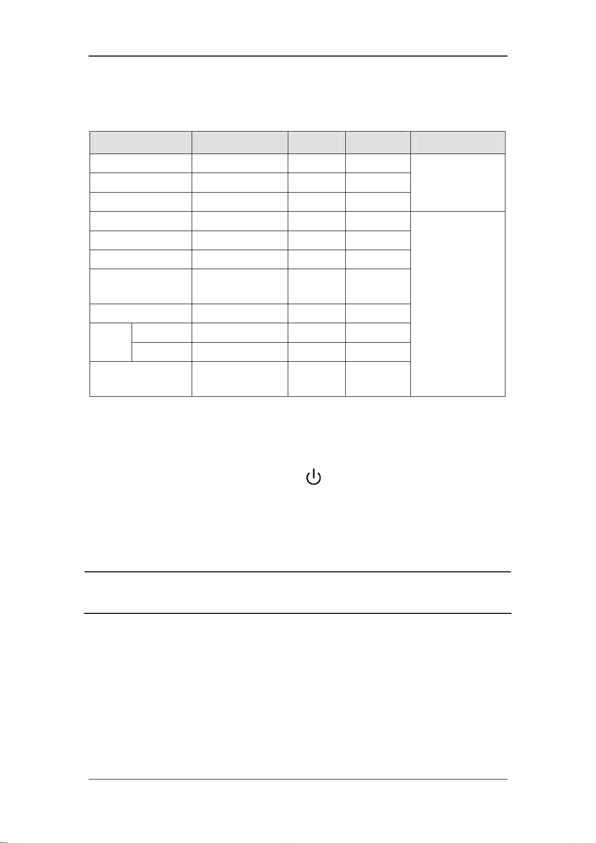
4.4.6.6 Parameter Range and Default Value in PSV Mode
Parameter Range Step Default Ventilation mode
Pinsp 5 to 60 cmH2O 1 cmH2O 15 cmH2O
Rate 4 to 60 BPM 1 BPM 10 BPM
I:E 4 to 100 BPM 1 BPM 12 BPM
Finsp 20 to 85 L/min 1 L/min 60 L/min
Plimit 10 to 100 cmH2O 1 cmH2O 30 cmH2O
Psupp 5 to 60 cmH2O 1 cmH2O 15 cmH2O
PEEP
Backup Mode Active 5 to 30 s 5 s 30 s
Trigger
Level
PSV Insp
Termination Level
Pressure -20 to -1 cmH2O 1 cmH2O -2 cmH2O
Flow 0.5 to 15 L/min 0.5 L/min 3 L/min
OFF, 4 to 30
cmH2O
5 to 60 % 5 % 25 %
1 cmH2O OFF
4.5 Start Mechanical Ventilation
PCV (backup
ventilation mode)
PSV
After settings of the related parameters are already made, you can enter mechanical
ventilation mode by pushing the Standby key
the pop-up menu to exit the standby status. The system will then work in the selected
mechanical ventilation mode.
on the panel and then selecting [Ok] from
NOTE
z Before starting a new mechanical ventilation mode, make sure that all related
parameters are set appropriately.
4-21

4.6 Set the Timer
4.6.1 Start the Timer
To start the timer, select the timer setup shortcut key and select [Start].
NOTE
z During timing, if you select [Start] from the [Timer Setup] menu again, timing
continues normally instead of restart.
4.6.2 Stop the Timer
To stop the timer, select the timer setup shortcut key and then [Stop]. The timer setup
shortcut key displays the time when timing stops.
NOTE
z When timing stops, if you select [Start] from the [Timer Setup] menu, the timer
starts timing from the time when timing last stopped.
4.6.3 Reset the Timer
To reset the timer, select the timer setup shortcut key and then [Reset]. The timer setup
shortcut key displays [00:00:00].
NOTE
z In timing status, if you select [Reset] from the [Timer Setup] menu, the timer is
stopped and reset.
4-22

4.7 Stop Mechanical Ventilation
To stop mechanical ventilation, do as follows:
1. Make sure that the breathing system is set up and the APL valve is set properly before
stopping mechanical ventilation.
The APL valve adjusts the breathing system pressure limit during manual ventilation. Its
scale shows approximate pressure.
2. Set the bag/mechanical ventilation switch to the
ventilation and stops mechanical ventilation (ventilator).
position. This selects manual
4-23

FOR YOUR NOTES
4-24

5 User Interface and Parameter Monitoring
5.1 Screen Layout
Depending on module and functional configurations, user screens differ in parameter&graph
area and parameter setup shortcut keys area.
User screens fall into four categories:
Standby screen
Normal screen
Big numerics screen
Measured values screen
The standby screen is switched over through the Standby key
easily switch between the other three types of screen by using the [Screens] shortcut key.
on the panel. You can
NOTE
z This manual describes all functions and modules. Some of the operations may be
inapplicable to your equipment.
z All illustrations in this manual serve as examples only. They may not necessarily
reflect the setup or data displayed on your anesthesia machine.
5-1

5.1.1 Standby Screen
When the anesthesia machine is not in use for a short period of time, entering standby status
can help save power and extend service life of the machine.
The anesthesia machine enters standby status automatically after start-up. To enter standby
status, you can also push the
pop-up menu. The following figure shows the standby screen.
key in operating mode and then select [Ok] from the
In standby status, the following changes occur to the system:
Displaying monitored parameters and waveforms is disabled. The system is in standby
status.
The ventilator stops supplying gases.
The parameters can be set. When the standby status exits, the system will operate based
on the final settings in standby status.
Physiological alarms are cleared automatically. Technical alarms function normally.
The gas module enters standby status.
To exit standby, push the
menu.
key in standby mode and then select [Ok] from the pop-up
5-2

5.1.2 Normal Screen
On the normal screen, parameter/graph area and waveform area are divided.
Parameter/graph area
The structure of these two areas varies depending on the configurations.
Waveform area
5.1.2.1 Parameter&graph Area
This area displays parameters and spirometry loops or electronic flowmeters as well. The
parameter&graph combinations displayed vary depending on the configurations.
1. Parameter information displayed includes:
Ventilator parameters
The following parameters may be displayed simultaneously depending on the configurations
of gas module and BIS module:
CO2 parameters
AG parameters
BIS parameters
2. Graph information displayed includes:
Spirometry loops
Electronic flowmeters
For details, refer to the respective sections of this chapter.
5.1.2.2 Waveform Area
This area displays waveforms monitored. The waveform combinations vary depending on the
configurations. The waveforms displayed include:
Paw waveform
Flow waveform
Volume waveform
CO2 waveform
AG module related waveforms
BIS module related waveforms
For details, refer to the respective sections of this chapter.
5-3

5.1.3 Special Screen
Special screen includes big numerics screen and measured values screen. The screen layout
is:
Parameter&graph
area
Big numerics/measured
values sharing area
5.1.3.1 Parameter&graph Area
This area may display:
CO2 parameters
AG parameters
BIS parameters
Electronic flowmeters
For details, refer to the respective sections of this chapter.
5.1.3.2 Big Numerics/Measured Values Sharing Area
This area displays either big numerics or measured values.
When screen layout is set to big numerics, this area is displayed as shown below.
5-4

When screen layout is set to measured values screen, this area displays Paw waveform
and ventilation parameters as shown below.
5.2 Screen Setup
To set the desired screen style,
1. Select the [Screens] shortcut key and select [Screens].
2. You can toggle between [Normal Screen], [Big Numerics] and [Measured Values].
5.3 Parameter Monitoring
5.3.1 O2 Concentration Monitoring
If your anesthesia machine is configured with an O2 sensor, select [Maintenance] → [User
Maintenance >>] → [Set O2 Sensor Monitoring >>]. Then select [ON] from the pop-up
menu to monitor the patient’s FiO2. Select [OFF] if you do not need to use the O2 sensor
monitoring function which the anesthesia machine has. You can make the following settings
when [O2 Sensor Monitoring] is set to [ON].
5.3.1.1 Switch on O2 Sensor or O2 Module
1. Select the [User Setup] shortcut key and select [O2 Monitoring Source >>].
2. Select [O2 Sensor] or [O2 Module] as desired. Select [OFF] if you do not need to use
the O2 sensor or O2 module.
3 Select
to exit the current menu.
5-5

5.3.1.2 Set FiO2 Alarm Limits
1. Select the [Alarm Setup] shortcut key and select [Ventilator >>].
2. Set FiO2 high and low alarm limits in the [Ventilator Alarm Limits] menu. When the
measured FiO2 exceeds the alarm limit, an alarm is generated.
3 Select
to exit the current menu.
NOTE
z When the O
concentration is accurately monitored. Calibrate the O
detected.
z When [OFF] is selected for [O2 Sensor Monitoring], O2 sensor calibration is
disabled. If [O2 Module] is selected for [O2 Monitoring Source], the functions
related to O2 module can still be performed.
z When [ON] is selected for [O2 Sensor Monitoring] and [OFF] for [O2 Monitoring
Source], FiO2 is displayed as invalid value. In this case, O2 sensor calibration,
FiO2 alarm limit setting, and alarm related to FiO2 and O2 sensor are all disabled.
z As required by the relevant international rules and regulations, O
monitoring needs to be performed when the anesthesia machine is used on the
patient. If your anesthesia machine is not configured with such monitoring
function, use a qualified monitor for O2 concentration monitoring.
sensor is used for the first time or is to be replaced, test that O2
2
sensor if a great error is
2
concentration
2
5.3.1.3 Display FiO2
If your anesthesia machine is configured with O2 module or O2 sensor, the monitored FiO2
parameter is displayed.
If AG module is configured, FiO2 is displayed together with AA concentration
parameters. For details, refer to 5.3.2.1Display AG Parameters.
If CO2 module is configured, FiO2 is displayed together with CO2 parameters. For
details, refer to 5.3.3.1Display CO2 Parameters.
If no gas module is configured, FiO2 is displayed together with tidal volume, breath rate
etc. For details, refer to 5.3.5.1Display Tidal Volume and Breath Rate Parameters.
5-6

5.3.1.4 Display O2 Waveform
If the AG module which your anesthesia machine is configured with incorporates an O2
module, an O2 waveform is displayed as shown below.
5.3.2 Anesthetic Agent (AA) Concentration Monitoring
If your anesthesia machine is configured with AG module, you can monitor FiAA and EtAA
by setting up the AG module. For details, refer to 9 AG and O2 Concentration Monitoring.
5.3.2.1 Display AG Parameters
If your anesthesia machine is configured with AG module, AG related parameters are
displayed as shown below.
[FiN2O]: Fraction of inspired nitrous oxide
[EtN2O]: End-tidal nitrous oxide
[FiEnf]: Fraction of inspired enflurane (displaying the concentration of the actually
selected anesthetic agent)
[EtEnf]: End-tidal enflurane (displaying the concentration of the actually selected
anesthetic agent)
[EtCO2]: End-tidal carbon dioxide
[FiCO2]: Fraction of inspired carbon dioxide
[MAC]: Minimum alveolar concentration
[FiO2]: Fraction of inspired oxygen
5-7
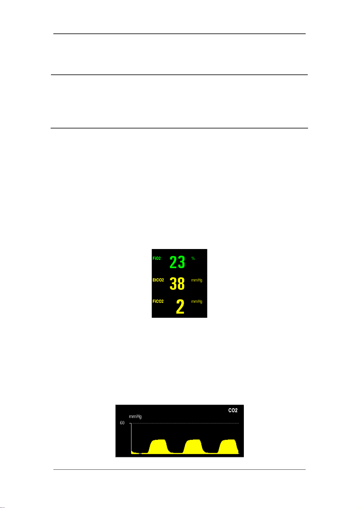
NOTE
z As required by the relevant international rules and regulations, anesthetic agent
concentration monitoring needs to be performed when the anesthesia machine is
used on the patient. If your anesthesia machine is not configured with such
monitoring function, use a qualified monitor for anesthetic agent concentration
monitoring.
5.3.3 CO2 Concentration Monitoring
If your anesthesia machine is configured with CO2 module, you can monitor FiCO2 and
EtCO2 by setting up the CO2 module.
If your anesthesia machine is configured with AG module, the system can also monitor
FiCO2 and EtCO2.
5.3.3.1 Display CO2 Parameters
If your anesthesia machine is configured with CO2 module, CO2 related parameters are
displayed as shown below.
[FiO2]: Fraction of inspired oxygen
[EtCO2]: End-tidal carbon dioxide
[FiCO2]: Fraction of inspired carbon dioxide
5.3.3.2 Display CO2 Waveform
If your anesthesia machine is configured with CO2 or AG module, a CO2 waveform is
displayed as shown below.
5-8

5.3.3.3 Other Settings
For details, refer to 8CO2 Monitoring and 9AG and O2 Concentration Monitoring.
NOTE
z As required by the relevant international rules and regulations, CO2 concentration
monitoring needs to be performed when the anesthesia machine is used on the
patient. If your anesthesia machine is not configured with such monitoring
function, use a qualified monitor for CO2 concentration monitoring.
5.3.4 Pressure Monitoring
5.3.4.1 Display Pressure Parameters
On the normal screen, the pressure related parameters are displayed as shown below.
[Ppeak]: Peak pressure
[Pplat]: Plateau pressure
[PEEP]: Positive end-expiratory pressure
5.3.4.2 Display Paw Waveform
5.3.4.3 Set Paw Waveform
1. Select the Paw waveform area to access the [Paw Waveform Setup] menu.
2. Select [Waveform] and select [Paw].
3. Select [Sweep] and toggle between [6.25 mm/s] and [12.5 mm/s].The greater the value
is, the faster the waveform sweeps.
5-9

4. Select to exit the current menu.
5. Set waveform scale. The Paw waveform scale is automatically adjusted based on the set
Plimit. You can set the Paw waveform scale appropriately by setting Plimit.
5.3.4.4 Set Paw Unit
1. Select the [Maintenance] shortcut key and select [User Maintenance >>].
2. Select [Paw Unit] and toggle between [cmH2O], [hPa] and [mbar].
3 Select
to exit the current menu.
5.3.4.5 Review Ppeak Trend
For details about reviewing Ppeak trend, refer to 12 Trend and Logbook.
5.3.5 Tidal Volume Monitoring
NOTE
z The tidal volume marked on the bellows housing is only a rough indicator. It may
be inconsistent with the tidal volume actually measured. This is a normal
phenomenon.
z As required by the relevant international rules and regulations, tidal volume
monitoring needs to be performed when the anesthesia machine is used on the
patient. If your anesthesia machine is not configured with such monitoring
function, use a qualified monitor for tidal volume monitoring.
5.3.5.1 Display Tidal Volume and Breath Rate Parameters
If your anesthesia machine is configured with CO2 or AG module, tidal volume and breath
rate related parameters are displayed as shown below.
5-10
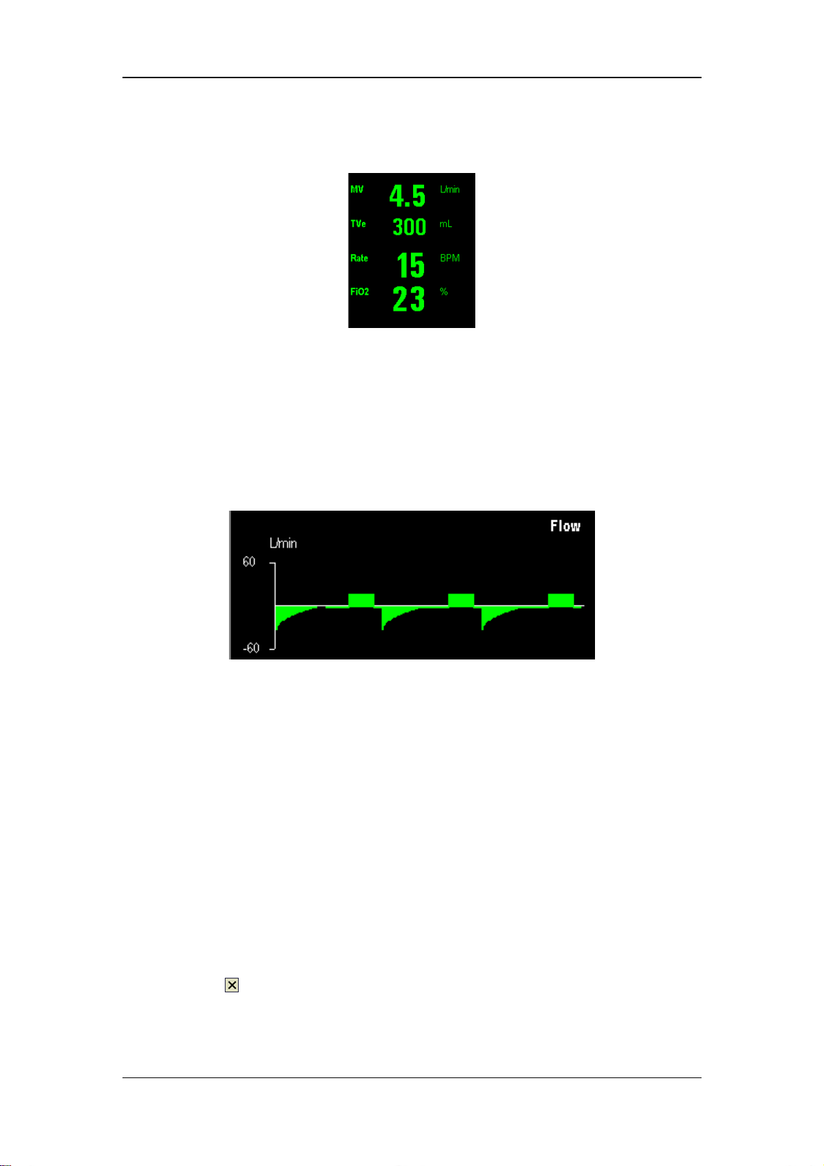
If your anesthesia machine is not configured with CO2 or AG module, tidal volume and
breath rate related parameters are displayed as shown below.
[MV]: Minute ventilation
[TVe]: Expired tidal volume
[Rate]: Breath rate
[FiO2]: Fraction of inspired oxygen
5.3.5.2 Display Flow Waveform
5.3.5.3 Set Flow Waveform
1. Select the flow waveform area to access the [Flow Waveform Setup] menu.
2. Select [Waveform] and select [Flow].
3. Select [Sweep] and toggle between [6.25 mm/s] and [12.5 mm/s]. The greater the value
is, the faster the waveform sweeps, the wider the waveform is.
4. Select [Scale] and toggle between [30], [60] and [120]. The unit is L/mm. The flow
ranges corresponding to the waveform scales are::
[30]: -30 to +30 L/min.
[60]: -60 to +60 L/min.
[120]: -120 to +120 L/min.
5. Select
to exit the current menu.
5-11

5.3.5.4 Set MV and TVe Alarm Limits
1. Select the [Alarm Setup] shortcut key and select [Ventilator >>].
2. Set MV high and low alarm limits in the [Ventilator Alarm Limits] menu.
3. Set TVe high and low alarm limits as required.
4 Select
to exit the current menu.
5.3.5.5 Review TVe and MV Trends
For details about reviewing TVe and MV trends, refer to 12 T r end and Logbook.
5.3.6 Tidal Volume Compensation
Tidal volume compensation compensates for lack of tidal volume due to the effects of
Fresh gas flow, or
Loss of gas compression, or
Breathing system compliance, or
Small amount of leakage, or
Combination of the factors above
, to achieve the consistency between actually delivered tidal volume and the set tidal volume.
By default, the system automatically performs tidal volume compensation.
If the measured tidal volume is quite different from the tidal volume indicated by the bellows,
you can turn off tidal volume compensation. By changing the set tidal volume or switching
over to pressure ventilation mode, you can achieve the consistency between the tidal volume
indicated by the bellows and the tidal volume required. To turn off tidal volume
compensation, do as follows:
1. Select the [User Setup] shortcut key.
2. Select [TV Comp] and select [OFF].
3. Select
If the current ventilation mode is VCV or SIMV-VC, the system prompts [TV Comp Off]
when tidal volume compensation is turned off.
In the volume ventilation mode, tidal volume compensation is turned off automatically if the
fresh gas pressure is too high, or the flow sensor has a great measurement deviation, or there
is significant leakage in the breathing system. In this case, the system prompts [TV Comp
Off] and the menu item of [TV Comp] turns grey indicating that this option is disabled. You
need to troubleshoot the problem. After the fault is troubleshot, the system prompts [TV
Comp A vailable]. You can set [TV Comp] to [ON] to restore the TV compensation function.
to exit the current menu.
5-12

5.3.7 Volume Monitoring
5.3.7.1 Display Volume Waveform
5.3.7.2 Set Volume Waveform
1. Select the waveform area to access the waveform setup menu.
2. Select [Waveform] and select [Volume].
3. Select [Sweep] and toggle between [6.25 mm/s] and [12.5 mm/s]. The greater the value
is, the faster the waveform sweeps.
4. Select [Scale] and toggle between [500], [1000], and [1500].The volume ranges
corresponding to the waveform scales are:
[500]: 0 to 500 ml.
[1000]: 0 to 1000 ml.
[1500]: 0 to 1500 ml.
5. Select
to exit the current menu.
5.3.8 Breath Rate Monitoring
5.3.8.1 Display Breath Rate
Refer to 5.3.5.1Display T idal Volume and Breath Rate Parameters.
5.3.8.2 Set Breath Rate Alarm Limits
1. Select the [Alarm Setup] shortcut key and select [Ventilator >>].
2. Set Rate high and low alarm limits in the [Ventilator Alarm Limits] menu.
3 Select
to exit the current menu.
5-13

5.3.9 BIS Monitoring
5.3.9.1 Display BIS Parameters
If your anesthesia machine is configured with BIS module, on the normal screen, BIS related
parameters are displayed as shown below.
[BIS]: Bispectral index
[SQI]: Signal quality index
[EMG]: Electromyograph
If your anesthesia machine is configured with BIS module, on the special screen, BIS related
parameters are displayed as shown below.
Non-Extend sensor Extend sensor
[BIS]: Bispectral index
[SQI]: Signal quality index
[EMG]: Electromyograph
[SR]: Suppression ratio
[SEF]: Spectral edge frequency
[TP]: Total power
[BC] : Burst count
5-14

5.3.9.2 Display BIS EEG Waveform
If your anesthesia machine is configured with BIS module, BIS EEG and BIS Trend
waveforms are displayed as shown below.
BIS EEG waveform:
BIS Trend waveform:
5.3.9.3 Set BIS EEG Waveform
1. Select the waveform area to access the waveform setup menu.
2. Select [Waveform] and select [BIS EEG].
3. Select [Sweep] and set waveform sweep speed to an appropriate value. The greater the
value is, the faster the waveform sweeps, the wider the waveform is.
4. Select [Scale] and set waveform scale to an appropriate value.
5. Select [Filters] and toggle between [ON] and [OFF].
6. Select
to exit the current menu.
5.3.9.4 Other Settings
For details, refer to 10 BIS Monitoring.
5-15

5.4 Display Electronic Flowmeter
Gas flow can be displayed either in a standard-resolution mode or high-resolution mode.
These two resolution modes vary in scale and accuracy.
Switchover between the standard-resolution mode and the high-resolution mode can be
performed manually based on gas flow. The default is high-resolution mode.
The scale range of the standard-resolution mode is 0 to 10 L/min and that of the
high-resolution mode 0 to 6 L/min.
To select the electronic flowmeter with desired resolution, select the electronic flowmeter
area to access the [Display Selection] menu.
When spirometry loop and gas modules are configured, you can select to display either
spirometry loop or electronic flowmeter. In this case, select the electronic flowmeters area to
open the [Display Selection] menu and then select the desired spirometry loop or electronic
flowmeter.
5.5 Spirometry Loop
Spirometry loops reflect patient lung function and ventilation as well, such as compliance,
over-inflation, breathing system leak and airway blockage.
The system provides two spirometry loops: P-V (Paw-volume) loop and F-V (flow-volume)
loop. Only one loop is displayed at a time: P-V loop or F-V loop. To switch over between the
two loops, select spirometry loop area and select the desired loop. The scales of volume flow
and Paw are adjusted automatically. The following figures show an F-V loop and a P-V loop.
5-16

6 Preoperative Test
6.1 Preoperative Test Schedules
6.1.1 Test Intervals
Perform the preoperative tests listed below at these events:
1. Before each patient.
2. When required after a maintenance or service procedure.
The following table indicates when a test must be done.
Test Item Test Intervals
Pipeline tests
Cylinder tests
Flow control system tests
Inspect the system
Alarm tests
Power failure alarm test
Breathing system tests
O2 Flush Test
Preoperative preparations
Inspect the AGSS
Every day before the first patient
Before each patient
NOTE
z Read and understand the operation and maintenance of each component before
using the anesthesia machine.
z Do not use the anesthesia machine if a test failure occurs. Contact us immediately.
z A checklist of the anesthetic system should be provided including aneshetic gas
delivery system, monitoring device, alarm system and protective device which are
intended to be used for the anesthetic system, whether they are used alone or
assembled together.
6-1

6.2 Inspect the System
NOTE
z Make sure that the breathing system is correctly connected and not damaged.
z The top shelf weight limit is 30 kg.
Make sure that:
1. The anesthesia machine is undamaged.
2. All components are correctly attached.
3. The breathing system is correctly connected, and the breathing tubes are undamaged.
4. The vaporizers are locked in position and contain sufficient agent.
5. The gas supplies are connected and the pressures are correct.
6. Cylinder valves are closed on models with cylinder supplies.
7. The necessary emergency equipment is available and in good condition.
8. Equipment for airway maintenance and tracheal intubation is available and in good
condition.
9. Applicable anesthetic and emergency drugs are available.
10. The casters are not damaged or loose and the brake (s) is set and prevents movement.
11. Make sure the breathing system is locked (in the
12. The AC mains indicator and the battery indicator come on when the power cord is
connected to the AC power source. If the indicators are not on, the system does not have
electrical power.
13. The anesthesia machine is switched on or off normally.
position).
6.3 Power Failure Alarm Test
1. Set the system switch to the position.
2. Disconnect the AC mains.
3. Make sure that the AC mains indicator is extinguished and the battery indicator is
flashing. Meanwhile, the prompt message [Battery in Use] is displayed.
4. Reconnect the AC mains.
6-2

5. Make sure that the AC mains indicator is illuminated and the battery indicator stops
flashing and continues illuminated. Meanwhile, the prompt message [Battery in Use]
disappears.
6. Set the system switch to the
position.
6.4 Pipeline Tests
NOTE
z Do not leave gas cylinder valves open if the pipeline supply is in use. Cylinder
supplies could be depleted, leaving an insufficient reserve supply in case of pipeline
failure.
6.4.1 O2 Pipeline Test
1. Close all cylinder valves and connect an O
with cylinders.
supply if the anesthesia machine is equipped
2
2. Set the system switch to the
position.
3. Set the flow controls to mid range.
4. Make sure that all pipeline pressure gauges show 280 to 600 kPa.
5. Disconnect the O
6. As O
pressure decreases, alarms for [O2 Supply Failure] and [Drive Gas Pressure
2
supply.
2
Low] should occur.
7. Make sure that the O
gauge goes to zero.
2
6-3

6.4.2 N2O Pipeline Test
Connect an O
Pipeline Test
supply before doing the N
2
NOTE
O pipeline test. For details, refer to 6.4.1O2
2
z When doing the N
control.
z Different from O
related to N
2
O pipeline test, connect O2 supply first to enable N2O flow
2
pipeline supply, when N2O supply is disconnected, no alarms
2
O pressure occur as N2O pressure decreases.
6.4.3 Air Pipeline Test
For details about Air pipeline test, refer to 6.4.1O2 Pipeline Test
NOTE
z Different from O2 pipeline supply, when Air supply is disconnected, no alarms
related to Air pressure occur as Air pressure decreases.
6.5 Cylinder Tests
You do not need to perform cylinder tests if the anesthesia machine is not equipped with
cylinders.
6.5.1 Check the Cylinder in Full Status
1. Set the system switch to the position and connect the cylinders to be checked.
2. Open each cylinder valve.
3. Make sure that each cylinder has sufficient pressure. If not, close the applicable cylinder
valve and install a full cylinder.
4. Close all cylinder valves.
6-4

6.5.2 O2 Cylinder High Pressure Leak Test
1. Set the system switch to the position and stop O2 pipeline supply.
2. Turn off the O
3. Open the O
flowmeter.
2
cylinder valve.
2
4. Record the current cylinder pressure.
5. Close the O
cylinder valve.
2
6. Record the cylinder pressure after one minute.
If the cylinder pressure decreases more than 5000 kPa (725 psi), there is a leak.
Install a new cylinder gasket as described in 13.5Install/Replace the Gas Cylinder.
Repeat steps 1 through 6. If the leak continues, do not use the cylinder supply
system.
6.5.3 N2O Cylinder High Pressure Leak Test
Refer to 6.5.2 O2 Cylinder High Pressure Leak Test to do the N2O cylinder high pressure
leak test. For N
represents a leak.
O cylinder, a pressure decrease of more than 700 kPa (100 psi) in one minute
2
6.6 Flow Control System Tests
6.6.1 Without O2 Sensor
WARNING
z Sufficient O
system.
z If N
O is available and flows through the system during this test, use a safe and
2
approved procedure to collect and remove it.
z Incorrect gas mixtures can cause patient injury. If the O
not supply O
NOTE
z Slowly open the cylinder valves to avoid damage. Do not adopt flow controls
forcibly.
in the fresh gas may not prevent hypoxic mixtures in the breathing
2
O Link system does
2-N2
and N2O in the correct proportions, do not use the system.
2
6-5

NOTE
z After doing the cylinder tests, close all cylinder valves if cylinder supplies are not
used.
z Turn the flow controls slowly. Do not turn further when the flow indicated on the
flowmeter is outside of the range to avoid damaging the control valve. When the
flow control is turned to the minimum, the reading indicated on the flowmeter
should be zero.
To do the flow control system tests:
1. Connect the pipeline supplies or slowly open the cylinder valves.
2. Turn all flow controls fully clockwise (minimum flow).
3. Set the system switch to the position.
4. Do not use the system if low battery or other ventilator failure alarms occur.
5. Adjust all gas flows to minimum.
6. Test the O
Turn the N
flow control counterclockwise and set the N
table. The O
O Link system with flow increasing:
2-N2
O and O2 flow controls fully clockwise (minimum flow). Then turn the N2O
2
O flow control to the rates shown in the
2
flow must meet the requirement listed in the following table.
2
Step N2O flow (L/min) O2 flow (L/min)
1 0.6 ≥0.2
2 1.5 ≥0.5
3 3.0 ≥1.0
4 7.5 ≥2.5
7. Test the O2-N2O Link system with flow decreasing:
Turn the N
above 3 L/min respectively. Then slowly turn the O
O flow control to the rates shown in the table. The O2 flow must meet the requirement
N
2
O and O2 flow controls and set the N2O flow to 9.0 L/min and the O2 flow to
2
flow control clockwise and set the
2
listed in the following table.
Step N2O flow (L/min) O2 flow (L/min)
1 7.5 ≥2.5
2 3.0 ≥1.0
3 1.5 ≥0.5
4 0.6 ≥0.2
8. Disconnect the O2 pipeline supply or close the O2 cylinder valve.
6-6

NOTE
z When O
Pressure Low] occur as O
supply is disconnected, alarms for [O2 Supply Failure] and [Drive Gas
2
pressure decreases.
2
9. Set the system switch to the position.
6.6.2 With O2 Sensor
Do as described in 6.9.2 Test the O2 Concentration Monitoring and Alarms before testing.
To do the flow control system tests:
1. Connect the pipeline supplies or slowly open the cylinder valves.
2. Turn all flow controls fully clockwise (minimum flow).
3. Set the system switch to the position.
4. Do not use the system if low battery or other ventilator failure alarms occur.
5. Adjust all gas flows to minimum.
Steps 6 and 7 are only for systems with N
2
O.
WARNING
z During steps 6 and 7, the O
system should be kept engaged.
z Adjust only the test control (N
z Test the flows in sequence (N
6. Test the O2-N2O Link system with flow increasing:
Turn the N
O and O2 flow controls fully clockwise (minimum flow).
2
Slowly turn the N
Make sure that the O
≥21% through the full range.
7. Test the O
Turn the N
O Link system with flow decreasing:
2-N2
O flow control and set the N2O flow to 9.0 L/min.
2
sensor used must be correctly calibrated and the Link
2
O in step 6 and O2 in step 7).
2
O then O2).
2
O flow control counterclockwise.
2
flow increases. The measured O2 concentration must be
2
Turn the O
flow control and set the O2 flow to 3 L/min or higher.
2
Slowly turn the O
flow control clockwise.
2
6-7

Make sure that the N
O flow decreases. The measured O2 concentration must be
2
≥21% through the full range.
8. Disconnect the O
pipeline supply or close the O2 cylinder valve.
2
9. Make sure that:
N
Air flow continues if Air supply is available.
Gas supply alarms occur on the ventilator.
O and O2 flows stop. The O2 flow stops last.
2
10. Turn all the flow controls fully clockwise (minimum flow).
11. Reconnect the O
pipeline supply or open the O2 cylinder valve.
2
12. Set the system to Standby.
6.7 Vaporizer Back Pressure Test
WARNING
z Use the Selectatec series vaporizers only. Make sure that the vaporizers are locked
when doing the test.
z During the test, the anesthetic agent comes out of the fresh gas outlet. Use a safe
and approved procedure to remove and collect the agent.
z To prevent damage, turn the flow controls fully clockwise (minimum flow or OFF)
before using the system.
Before the test, make sure that the vaporizers are correctly installed. For details about
vaporizer installation, refer to 13.4 Install the Vaporizer.
1. Connect the O
2. Turn the O
3. Make sure that the O
4. Adjust the vaporizer concentration from 0 to 1%. Make sure that the O
pipeline supply or open the O2 cylinder valve.
2
flow control and set the O2 flow to 6 L/min.
2
flow stays constant.
2
flow must not
2
decrease more than 1 L/min through the full range. Otherwise, install a different
vaporizer and try this step again. If the problem persists, the malfunction is in the
anesthesia system. Do not use this system.
5. Test each vaporizer as per the steps above.
6-8

NOTE
z Do not perform test on the vaporizer when the concentration control is between
“OFF” and the first graduation above “0” (zero) as the amount of anesthetic drug
outputted is very small within this range.
6.8 Breathing System Tests
WARNING
z Objects in the breathing system can stop gas flow to the patient. This can cause
injury or death. Make sure that there are no test plugs or other objects in the
breathing system.
z Do not use a test plug that is small enough to fall into the breathing system.
1. Make sure that the breathing system is correctly connected and not damaged.
2. Make sure that the check valves in the breathing system work correctly:
The inspiratory check valve opens during inspiration and closes at the start of
expiration.
The expiratory check valve opens during expiration and closes at the start of
inspiration.
6.8.1 Bellows Test
1. Set the system to Standby.
2. Set the bag/mechanical ventilation switch to the mechanical ventilation position.
3. Set all flow controls to minimum.
4. Close the breathing system at the patient connection.
5. Push the O2 flush button to fill the bellows, folding bag rising to the top.
6. Make sure that the pressure must not increase to more than 15 cmH
pressure gauge.
7. The folding bag should not fall. If it falls, it has a leak. You need to reinstall the bellows.
6-9
O on the airway
2

6.8.2 Breathing System Leak Test in Mechanical Ventilation
Status
NOTE
z Breathing system leak test must be performed when the system is in standby status.
z Before doing the breathing system leak test, make sure that the breathing system is
correctly connected and the breathing tubes not damaged.
1. Make sure that the system is Standby. If not, press the key and select [Ok] from the
pop-up menu to enter standby status.
2. Connect the Y piece on the breathing tube to the leak test plug on the breathing system.
Occlude the gas outlet of the Y piece.
3. Turn the O
4. Push the O
5. Select the [Maintenance] shortcut key and then select [Breathing System Leak Test
>>].
6. Select [Start] to start the breathing system leak test. The screen prompts [Performing
leak test].
7. After a successful test, the screen shows [Leak Test Passed!]. Otherwise, the message
[Leak Test Failure! Please try again.] is displayed. In this case, you need to check that
the breathing system is correctly connected and the tubes are not damaged before doing
the leak test again.
8. Select
flow control to set O2 flow to 0.15-0.2 L/min.
2
flush button to fill the bellows, folding bag rising to the top.
2
to exit the current menu.
NOTE
z During the leak test, if you select [Stop], test is stopped. Then the message [Leak
Test Stopped! Leak test is unfinished.] is displayed. This indicates invalid test
instead of test failure.
z In case of leak test failure, check all possible leak sources, including bellows,
breathing tubes, and sodalime canister. Check that they are correctly connected
and their connectors are undamaged. When checking the sodalime canister, check
if there is sodalime attaching the sealing component of the canister. If there is, clear
the sodalime
z Do not use the anesthesia machine if breathing system leak occurs. Contact your
service personnel or us.
6-10

6.8.3 Breathing System Leak Test in Manual Ventilation Status
1. Make sure that the system is Standby. If not, press the key and select [Ok] from the
pop-up menu to enter standby status.
2. Set the bag/mechanical ventilation switch to the bag position.
3. Connect the manual bag to the manual bag port.
4. Turn the APL valve control to fully close the APL valve (75 cmH
5. Turn the O
flow control to set the O2 flow to 0.15-0.2 L/min.
2
2
O).
6. Connect the Y piece on the breathing tube to the leak test plug on the manual bag port.
Occlude the gas outlet of the Y piece.
7. Push the O
flush button to let the pressure increase to approximately 30 cmH2O on the
2
airway pressure gauge.
8. Release the flush button. A pressure decrease on the airway pressure gauge indicates a
leak. Look for and please contact your service personnel.
6.8.4 APL Valve Test
1. Make sure that the system is Standby. If not, press the key and select [Ok] from the
pop-up menu to enter Standby.
2. Set the bag/mechanical ventilation switch to the bag position.
3. Connect the manual bag to the manual bag port.
4. Connect the Y piece on the breathing tube to the leak test plug on the manual bag port.
5. Turn the APL valve control to let the pressure of APL valve stay at 30 cmH
2
O.
6. Push the O2 flush button to inflate the manual bag.
7. Make sure that the reading on the airway pressure gauge is with the range of 20 to 40
O.
cmH
2
8. Turn the APL valve control to the MIN position.
9. Set the O
10. Make sure that the reading on the airway pressure gauge is less than 5 cmH
11. Push the O
flow to 3 L/min. Turn any other gases off.
2
O.
2
flush button. Make sure that the reading on the airway pressure gauge does
2
not exceed 10 cmH2O.
12. Turn the O
the airway pressure gauge does not decrease below 0 cmH
flow control to set the O2 flow to minimum. Make sure that the reading on
2
O.
2
6-11

6.9 Alarm Tests
The anesthesia machine performs a self test after started. The alarm lamp flashes yellow and
red once in turn and then a beep is given. Then the display shows the start-up screen and
enters the standby screen after 30 seconds. This means that audio and visual alarm indicators
begin to work normally.
6.9.1 Prepare for Alarm Tests
1. Connect a test lung or manual bag to the Y piece patient connection.
2. Set the bag/mechanical ventilation switch to the mechanical ( ) position.
3. Set the system switch to the
position.
4. Set the system to Standby.
5. Set the ventilator controls as follows:
Ventilation mode: select the [Vent Mode] shortcut key and then [VCV].
[TV]: 500 ml.
[Rate]: 12 BPM.
[I:E]: 1:2.
[Plimit]: 30 cmH
[PEEP]: OFF.
6. Push the O
7. Turn the O
8 Press the
flush button to fill the bellows, folding bag rising to the top.
2
flow control to set the O2 flow to 0.5 to 1 L/min.
2
key and select [Ok] from the pop-up menu to exit the standby status.
2
O.
9. Make sure that:
The ventilator displays the correct data.
The folding bag inside the bellows inflates and deflates normally during
mechanical ventilation.
6-12

6.9.2 Test the O2 Concentration Monitoring and Alarms
NOTE
z This test is not required if no O
sensor is configured.
2
1. Set the bag/mechanical ventilation switch to the bag position.
2. Remove the O
approximately 21% O
sensor. After two to three minutes, make sure that the sensor measures
2
in room air.
2
3. Select the [Alarm Setup] shortcut key and then [Ventilator >>]. Set the FiO
limit to 50%.
4. Make sure that a low FiO
5. Set the FiO
low alarm limit back to a value less than the measured FiO2 value and make
2
alarm occurs.
2
sure that the alarm cancels.
6. Put the O
sensor back in the breathing system.
2
7. Select the [Alarm Setup] shortcut key and then [Ventilator >>]. Set the FiO
alarm limit to 50%.
8. Connect the manual bag to the manual bag port. Push the O
manual bag. Make sure that the sensor measures approximately 100% O
9. Make sure that a high FiO
alarm occurs.
2
flush button to fill the
2
2.
low alarm
2
high
2
10. Set the FiO
high alarm limit to 100% and make sure that the alarm cancels.
2
6.9.3 Test the Low Minute Volume Alarm
1. Make sure that MV alarm is switched on.
2. Select the [Alarm Setup] shortcut key and then [Ventilator >>]. Set the MV low alarm
limit to 8.0 L/min.
3. Make sure that a low MV alarm occurs.
4. Select the [Alarm Setup] shortcut key and then [Ventilator >>]. Set the MV low alarm
limit to 2.0 L/min.
6-13

6.9.4 Test the Apnea Alarm
1. Connect the manual bag to the manual bag port
2. Set the bag/mechanical ventilation switch to the bag
position.
3. Turn the APL valve control to set the APL valve to the minimum position.
4. Inflate the manual bag to make sure that a complete breathing cycle occurs.
5. Stop inflating the manual bag and wait for more than 20 seconds to make sure that the
apnea alarm occurs.
6. Inflate the manual bag to make sure that the alarm cancels.
6.9.5 Test the Sustained Airway Pressure Alarm
1. Connect the manual bag to the manual bag port.
2. Turn the O
3. Turn the APL valve control to set the APL valve to 30 cmH
4. Set the bag/mechanical ventilation switch to the bag
flow control to set the O2 flow to minimum.
2
O position.
2
position.
5. Push the O
flush button for approximately 15 seconds. Make sure that the sustained
2
airway pressure alarm occurs.
6. Open the patient connection and make sure that the alarm cancels.
6.9.6 Test the High Paw Alarm
1. Set the bag/mechanical ventilation switch to the mechanical position.
2. Select the [Alarm Setup] shortcut key and then [Ventilator >>].
3. Set the Paw low alarm limit to 0 cmH2O and Paw high alarm limit to 5 cmH2O.
4. Make sure that a high Paw alarm occurs.
5. Set the Paw high alarm limit to 40 cmH
6. Make sure the high Paw alarm cancels.
2
O.
6-14

6.9.7 Test the Low Paw Alarm
1. Set the bag/mechanical ventilation switch to the mechanical position.
2. Select the [Alarm Setup] shortcut key and then [Ventilator >>].
3. Set the Paw low alarm limit to 2 cmH2O.
4. Disconnect the manual bag from the Y piece patient connection.
5. Wait for 20 seconds. View the alarm area and make sure that a low Paw alarm occurs.
6. Connect the manual bag to the manual bag port.
7. Make sure the low Paw alarm cancels.
6.9.8 Test the AG Module Alarm
1. Refer to 13.6.2Install the AG Module and then refer to9.4Prepare to Measure AG.
2. Disconnect the gas sampling tube and connect the tube to the standard gas bag filled
with AA (5% CO2 must be contained). AA stands for any of the five anesthetic agents:
Des (desflurane), Iso (isoflurane), Enf (enflurane), Sev (sevoflurane), or Hal (halothane).
3. Select the [Alarm Setup] shortcut key and then [Gas Module >>]
4. Set the EtAA high alarm limit to be lower than the concentration of the standard gas.
5. Make sure that a high EtAA alarm occurs.
6. Set the EtAA low alarm limit to be higher than the concentration of the standard gas.
7. Make sure that a low EtAA alarm occurs.
6.10 Preoperative Preparations
1. Make sure that the ventilator parameters and alarm limits are set to applicable clinical
levels. For details, refer to 4 Operations and Ventilation Setup.
2. Make sure that the system is Standby.
3. Make sure that the equipment for airway maintenance, manual ventilation and tracheal
intubation, and applicable anesthetic and emergency drugs are available.
4. Set the bag/mechanical ventilation switch to the bag position.
5. Connect the manual bag to the manual bag port.
6. Turn off all vaporizers.
7. Turn the APL valve control to fully open the APL valve (MIN position).
8. Turn all flow controls to set all gas flows to minimum.
9. Make sure that the breathing system is correctly connected and not damaged.
6-15

WARNING
z Before connecting a patient, flush the anesthesia machine with 5 L/min of O
least one minute. This removes unwanted mixtures and by-products from the
system.
6.11 Inspect the AGSS
Assemble the AGSS as described in 13.10.2Assemble the AGSS and then turn on the waste
gas disposal system. Check if the float can rise and exceed the “MIN” mark. If any blockage,
tackiness, or damage occurs to the float, disassemble and assemble the float again or replace
the float.
NOTE
z Do not block the AGSS pressure compensation openings during the inspection.
If the float cannot rise, the possible reasons are:
for at
2
1. The float is tacky. Turn over the AGSS and check if the float moves up and down freely.
2. The float is rising slowly. The filter may be blocked. Check if the filter is blocked as
described in 14.2.13.1Filter.
3. The waste gas disposal system is not working or the pump rate is less than 50 L/min at
which the AGSS works normally. Check the waste gas disposal system as described in
13.10.3 Waste Gas Disposal System.
6-16

7 User Maintenance
7.1 Repair Policy
WARNING
z Only use lubricants approved for anesthesia or O
z Do not use lubricants that contain oil or grease. They burn or explode in high O
concentrations.
z Obey infection control and safety procedures. Used equipment may contain blood
and body fluids.
z Movable parts and removable components may present a pinch or a crush hazard.
Use care when moving or replacing system parts and components.
Do not use malfunctioning anesthesia machine. Have all repairs and service done by an
authorized service representative. Replacement and maintenance of tube parts listed in this
manual may be undertaken by a competent, trained individual having experience in the repair
of devices of this nature.
After repair, test the anesthesia machine to ensure that it is functioning properly, in
accordance with the specifications.
equipment.
2
2
NOTE
z No repair should ever be attempted by anyone not having experience in the repair
of devices of this nature.
z Replace damaged parts with components manufactured or sold by us. Then test the
unit to make sure that it complies with the manufacturer’s published specifications.
z Contact us for service assistance.
z For further information about the product, contact us. We can provide documents
about some parts depending on the actual condition.
7-1

7.2 Maintenance Schedule
NOTE
z These schedules are the minimum frequency based on typical usage of 2000 hours
per year. You should service the equipment more frequently if you use it more than
the typical yearly usage.
Minimum
frequency
Daily
Biweekly Drain the vaporizers.
Monthly
During cleaning
and setup
Annually
Every three
years
Maintenance
Clean the external surfaces.
21%O2 calibration (O2 sensor in breathing system).
100% O
Clear water built up inside the waterstraps of CO2 module and AG module.
Inspect the parts and seals for damage. Replace or repair as necessary.
Replace the seal on the vaporizer manifold and that on the breathing system
port. Contact us for details.
CO2 module calibration.
AG module calibration.
Replace the built-in lithium-ion batteries. Contact us for details.
Before installing the cylinder, use a new cylinder gasket on cylinder yoke.
Empty the water collection cup If there is water built up in it.
calibration (breathing system O2sensor).
2
As necessary
Replace the sodalime in the canister if sodalime color change is detected.
Replace the O2 sensor if a great deviation of the measured value by the O2
sensor occurs and the problem persists after multiple calibrations.
Replace the flow sensor if the seal for the flow sensor is damaged, the
membrane inside the flow sensor is cracked or distorted, or the flow sensor is
cracked or distorted.
Replace the transfer tube if it is damaged.
7-2
 Loading...