

Page 1

DC-35/DC-40/DC-45/DC-40S/DC-40 Pro
Diagnostic Ultrasound System
Operator’s Manual
[Basic Volume]
Page 2

Page 3

Contents
Intellectual Property Statement .......................................................................................................... I
Responsibility on the Manufacturer Party .......................................................................................... I
Warranty ............................................................................................................................................ II
Exemptions ................................................................................................................................... II
Customer Service Department ..................................................................................................... II
Important Information ....................................................................................................................... III
About This Manual ........................................................................................................................... III
Notation Conventions ....................................................................................................................... III
Operator’s Manuals .......................................................................................................................... IV
Manuals on Paper ............................................................................................................................ IV
Software Interfaces in this Manual .................................................................................................... V
Conventions ...................................................................................................................................... V
1 Safety Precautions ..................................................................................................... 1-1
1.1 Safety Classification ............................................................................................................. 1-1
1.2 Meaning of Signal Words ..................................................................................................... 1-2
1.3 Meaning of Safety Symbols ................................................................................................. 1-2
1.4 Safety Precautions ............................................................................................................... 1-3
1.5 Latex Alert ............................................................................................................................ 1-9
1.6 Warning Labels .................................................................................................................. 1-10
2 System Overview ........................................................................................................ 2-1
2.1 Intended Use ........................................................................................................................ 2-1
2.2 Contraindication ................................................................................................................... 2-1
2.3 Product and Model Code ..................................................................................................... 2-1
2.4 Product Specifications .......................................................................................................... 2-1
2.4.1 Imaging Mode ............................................................................................................... 2-1
2.4.2 Power supply ................................................................................................................ 2-2
2.4.3 Environmental Conditions ............................................................................................. 2-2
2.4.4 Size and Weights .......................................................................................................... 2-3
2.5 System Configuration ........................................................................................................... 2-3
2.5.1 Standard Configuration ................................................................................................. 2-3
2.5.2 Probes Available ........................................................................................................... 2-3
2.5.3 Options ......................................................................................................................... 2-4
2.5.4 Peripherals Supported .................................................................................................. 2-5
2.6 Introduction of Each Unit ...................................................................................................... 2-6
2.7 I/O Panel .............................................................................................................................. 2-9
2.8 Power Supply Panel ........................................................................................................... 2-10
2.9 Physiological-signal Panel ................................................................................................. 2-10
2.10 Control Panel ...................................................................................................................... 2-11
2.11 Symbols .............................................................................................................................. 2-16
3 System Preparation .................................................................................................... 3-1
3.1 Move/Posit the System ........................................................................................................ 3-1
3.2 Power Supply ....................................................................................................................... 3-2
3.2.1 Connecting AC Power Supply ...................................................................................... 3-2
3.2.2 Powered by Batteries ................................................................................................... 3-3
3.2.3 Equipotential Terminal .................................................................................................. 3-3
3.3 Power ON/OFF ..................................................................................................................... 3-3
3.3.1 Powering ON the System ............................................................................................. 3-3
i
Page 4

3.3.2 Powering OFF the System ........................................................................................... 3-5
3.3.3 Standby ......................................................................................................................... 3-5
3.4 Monitor Adjusting .................................................................................................................. 3-6
3.4.1 Monitor Position Adjusting ............................................................................................ 3-6
3.4.2 Adjusting Brightness/Contrast on the Monitor .............................................................. 3-7
3.4.3 Control Panel Position Adjustment ............................................................................... 3-8
3.5 Connecting a Probe.............................................................................................................. 3-9
3.5.1 Connecting a Probe ...................................................................................................... 3-9
3.5.2 Disconnecting a probe .................................................................................................. 3-9
3.6 Connecting Peripheral Devices .......................................................................................... 3-10
3.6.1 Connecting the USB Devices ..................................................................................... 3-10
3.6.2 Connecting a Footswitch ............................................................................................ 3-10
3.6.3 Graph /Text printer ...................................................................................................... 3-11
3.6.4 Installing Analog Video Printer .................................................................................... 3-14
3.6.5 Installing Digital Video Printer ..................................................................................... 3-16
3.6.6 Installing a Wireless Printer ........................................................................................ 3-16
3.6.7 Installing/ uninstalling Probe/Gel Holder ..................................................................... 3-16
3.7 Basic Screen and Operation .............................................................................................. 3-18
3.7.1 Basic Screen ............................................................................................................... 3-18
3.7.2 Basic Operations of Screens ...................................................................................... 3-22
3.7.3 Touchscreen ............................................................................................................... 3-23
3.7.4 Soft keyboard .............................................................................................................. 3-24
4 Exam Preparation ....................................................................................................... 4-1
4.1 To Start an Exam .................................................................................................................. 4-1
4.2 Patient Information ............................................................................................................... 4-1
4.2.1 New Patient Information ............................................................................................... 4-1
4.2.2 Retrieve Patient Information ......................................................................................... 4-5
4.3 Select Exam Mode and Probe ............................................................................................. 4-8
4.3.1 Dual-probe Switch ........................................................................................................ 4-8
4.4 Select the Imaging Mode ..................................................................................................... 4-9
4.5 Activate& Continue an Exam ............................................................................................... 4-9
4.5.1 Activate an Exam .......................................................................................................... 4-9
4.5.2 Continue Exam ............................................................................................................. 4-9
4.6 Pause & End an Exam ......................................................................................................... 4-9
4.6.1 Pause Exam ................................................................................................................. 4-9
4.6.2 End Exam ................................................................................................................... 4-10
5 Image Optimization ..................................................................................................... 5-1
5.1 Imaging Mode ....................................................................................................................... 5-1
5.1.1 Switching Between Imaging Modes .............................................................................. 5-1
5.1.2 Image Adjustment ......................................................................................................... 5-1
5.1.3 Quickly Saving Image Settings ..................................................................................... 5-2
5.2 B Mode Image Optimization ................................................................................................. 5-3
5.2.1 Basic Procedures for B Mode Imaging ......................................................................... 5-3
5.2.2 B Mode Parameters ...................................................................................................... 5-3
5.2.3 B Mode Image Optimization ......................................................................................... 5-4
5.3 M Mode Image Optimization .............................................................................................. 5-10
5.3.1 Basic Procedures for M Mode Imaging ...................................................................... 5-10
5.3.2 M Mode Image Parameters ........................................................................................ 5-10
5.3.3 M Mode Image Optimization ....................................................................................... 5-11
5.4 Color Mode Image Optimization ......................................................................................... 5-13
ii
Page 5

5.4.1 Basic Procedures for Color Mode Imaging ................................................................. 5-13
5.4.2 Color Mode Image Parameters .................................................................................. 5-13
5.4.3 Color Mode Image Optimization ................................................................................. 5-13
5.5 Power Mode Image Optimization ....................................................................................... 5-18
5.5.1 Basic Procedures for Power Mode Imaging ............................................................... 5-18
5.5.2 Power Mode Image Parameters ................................................................................. 5-18
5.5.3 Power Mode Image Optimization ............................................................................... 5-18
5.6 PW/CW Doppler Mode ....................................................................................................... 5-20
5.6.1 Basic Procedures for PW/CW Mode Exam ................................................................ 5-20
5.6.2 PW/CW Mode Image Parameters .............................................................................. 5-21
5.6.3 PW/CW Mode Image Optimization ............................................................................. 5-22
5.7 Color M Mode ..................................................................................................................... 5-27
5.7.1 Enter Color M Mode.................................................................................................... 5-27
5.7.2 Exit Color M Mode ...................................................................................................... 5-27
5.7.3 Color M Mode Image Parameters .............................................................................. 5-27
5.8 Anatomical M Mode............................................................................................................ 5-28
5.8.1 Free Xros M Imaging (Anatomical M-Mode) .............................................................. 5-28
5.8.2 Free Xros CM (Curved Anatomical M-Mode) ............................................................. 5-29
5.9 TDI ...................................................................................................................................... 5-30
5.9.1 Basic Procedures for TDI Imaging .............................................................................. 5-31
5.9.2 TDI Image Parameters ............................................................................................... 5-31
5.9.3 TDI Image Optimization .............................................................................................. 5-31
5.9.4 TDI Quantitative Analysis (QA) ................................................................................... 5-32
5.10 3D/4D ................................................................................................................................. 5-36
5.10.1 Overview ..................................................................................................................... 5-36
5.10.2 Note Before Use ......................................................................................................... 5-40
5.10.3 Static 3D ..................................................................................................................... 5-42
5.10.4 iLive ............................................................................................................................ 5-52
5.10.5 4D ............................................................................................................................... 5-54
5.10.6 Smart 3D ..................................................................................................................... 5-55
5.10.7 iPage (Multi-Slice Imaging) ......................................................................................... 5-57
5.11 iScape View (Real-time Panoramic Imaging)..................................................................... 5-61
5.11.1 Basic Procedures for iScape Imaging ........................................................................ 5-61
5.11.2 Image Acquisition........................................................................................................ 5-62
5.11.3 iScape Viewing ........................................................................................................... 5-62
5.11.4 Cine Review ................................................................................................................ 5-64
5.12 Elastography ...................................................................................................................... 5-64
5.12.1 Basic Procedure for Elastography .............................................................................. 5-64
5.12.2 Enter/Exit .................................................................................................................... 5-65
5.12.3 Pressure Hint Curve ................................................................................................... 5-65
5.12.4 Cine Review ................................................................................................................ 5-66
6 Display & Cine Review ............................................................................................... 6-1
6.1 Image Display ....................................................................................................................... 6-1
6.1.1 Splitting Display ............................................................................................................ 6-1
6.2 Image Magnification ............................................................................................................. 6-1
6.2.1 Spot ............................................................................................................................... 6-1
6.2.2 Pan ............................................................................................................................... 6-2
6.2.3 iZoom (Full-screen Zooming) ....................................................................................... 6-2
6.3 Freeze/Unfreeze the Image ................................................................................................. 6-2
6.3.1 Imaging Mode Switching When Frozen ........................................................................ 6-2
6.3.2 Imaging Display Format Switching When Frozen ........................................................ 6-3
iii
Page 6

6.4 Cine Review ......................................................................................................................... 6-3
6.4.1 Entering/ Exiting Cine Review ...................................................................................... 6-4
6.4.2 Cine Review in 2D Mode (B/B+Color/B+Power/B+TVI/B+TEI) .................................... 6-4
6.4.3 Cine Review in M or D Mode ........................................................................................ 6-5
6.4.4 Linked Cine Review ...................................................................................................... 6-5
6.5 Image Compare .................................................................................................................... 6-6
6.5.1 Cine Compare ............................................................................................................... 6-6
6.5.2 Frame Compare ............................................................................................................ 6-6
6.6 Cine Saving .......................................................................................................................... 6-6
6.7 Cine Memory ........................................................................................................................ 6-7
6.7.1 Cine Memory Setting .................................................................................................... 6-7
6.8 Cine Settings ........................................................................................................................ 6-8
7 ECG .............................................................................................................................. 7-1
7.1 ECG Operation Basic Procedures ....................................................................................... 7-2
7.2 Parameter Description ......................................................................................................... 7-2
7.3 ECG Review ......................................................................................................................... 7-3
8 Measurement ............................................................................................................... 8-1
8.1 Basic Operations .................................................................................................................. 8-1
8.2 General Measurements ........................................................................................................ 8-2
8.2.1 2D General Measurements .......................................................................................... 8-2
8.2.2 M General Measurements ............................................................................................ 8-2
8.2.3 Doppler General Measurements .................................................................................. 8-3
8.3 Application Measurement ..................................................................................................... 8-3
8.4 Measurement Accuracy ........................................................................................................ 8-5
9 Comments and Body Marks ...................................................................................... 9-1
9.1 Comments (Annotations) ...................................................................................................... 9-1
9.1.1 Comments Basic Procedures ....................................................................................... 9-1
9.1.2 Touch Screen Display in Comments ............................................................................. 9-2
9.1.3 Adding Comments ........................................................................................................ 9-3
9.1.4 Moving Comments ........................................................................................................ 9-5
9.1.5 Modifying (Editing) Comments ..................................................................................... 9-5
9.1.6 Deleting Comments ...................................................................................................... 9-6
9.1.7 Comment Setting .......................................................................................................... 9-6
9.2 Body Marks .......................................................................................................................... 9-6
9.2.1 Touch Screen Display in Body Mark ............................................................................. 9-6
9.2.2 Adding Body Marks....................................................................................................... 9-7
9.2.3 Moving Body Marks ...................................................................................................... 9-7
9.2.4 Deleting Body Marks..................................................................................................... 9-7
10 Patient Data Management ........................................................................................ 10-1
10.1 Patient Information Management ....................................................................................... 10-1
10.1.1 Enter Patient Information ............................................................................................ 10-1
10.1.2 Patient Information Setting ......................................................................................... 10-1
10.2 Image File Management .................................................................................................... 10-2
10.2.1 Memory Media ............................................................................................................ 10-2
10.2.2 Image File Formats ..................................................................................................... 10-2
10.2.3 Image Storage Preset ................................................................................................. 10-3
10.2.4 Quickly Saving Images to the System ........................................................................ 10-3
10.2.5 Quickly Saving Full Screen Image to the System ...................................................... 10-4
10.2.6 Thumbnails ................................................................................................................. 10-4
iv
Page 7

10.2.7 Image Review and Analysis ........................................................................................ 10-4
10.2.8 iVision ......................................................................................................................... 10-6
10.2.9 Sending Image File ..................................................................................................... 10-8
10.3 Report Management........................................................................................................... 10-9
10.4 Patient Data Management (iStation) ................................................................................ 10-10
10.4.1 Viewing Patient Information ...................................................................................... 10-10
10.4.2 Searching a Patient .................................................................................................. 10-11
10.4.3 Patient Data View & Management ............................................................................ 10-11
10.5 iStorage ............................................................................................................................ 10-13
10.6 Print .................................................................................................................................. 10-13
10.6.1 Setting ....................................................................................................................... 10-13
10.6.2 Image Print ................................................................................................................ 10-13
10.6.3 Report Print ............................................................................................................... 10-14
10.7 Backup Files through DVD Drive ..................................................................................... 10-14
10.8 Patient Task Management ................................................................................................ 10-15
10.9 Administration ................................................................................................................... 10-16
10.9.1 Access Setting .......................................................................................................... 10-16
10.9.2 Setting Access Control ............................................................................................. 10-16
10.9.3 System Login ............................................................................................................ 10-16
10.9.4 Adding/Deleting a User ............................................................................................. 10-17
10.9.5 Modify Password ...................................................................................................... 10-18
11 DICOM .........................................................................................................................11-1
11.1 DICOM Preset .................................................................................................................... 11-1
11.1.1 Network Preset ........................................................................................................... 11-1
11.1.2 DICOM Local Preset ................................................................................................... 11-2
11.1.3 Service Preset ............................................................................................................ 11-3
11.2 Verify Connectivity .............................................................................................................. 11-8
11.3 DICOM Services ................................................................................................................. 11-8
11.3.1 DICOM Storage .......................................................................................................... 11-8
11.3.2 DICOM Print ............................................................................................................. 11-10
11.3.3 DICOM Worklist ......................................................................................................... 11-11
11.3.4 MPPS ........................................................................................................................ 11-12
11.3.5 Storage Commitment ................................................................................................ 11-12
11.3.6 Query/Retrieve .......................................................................................................... 11-13
11.4 DICOM Media Storage ..................................................................................................... 11-14
11.5 Structured Report ............................................................................................................. 11-15
11.6 DICOM Task Management ............................................................................................... 11-15
12 Setup .......................................................................................................................... 12-1
12.1 System Preset .................................................................................................................... 12-1
12.1.1 Region ........................................................................................................................ 12-3
12.1.2 General ....................................................................................................................... 12-4
12.1.3 Image Preset .............................................................................................................. 12-5
12.1.4 Application .................................................................................................................. 12-6
12.1.5 OB Preset ................................................................................................................... 12-6
12.1.6 Key Configuration ....................................................................................................... 12-6
12.1.7 Admin .......................................................................................................................... 12-7
12.2 Exam Preset ....................................................................................................................... 12-8
12.3 Measure Preset .................................................................................................................. 12-8
12.4 Print Preset ......................................................................................................................... 12-9
12.5 Network Preset ................................................................................................................. 12-10
v
Page 8

12.5.1 Local TCP/IP ............................................................................................................. 12-10
12.5.2 iStorage ..................................................................................................................... 12-12
12.5.3 MedTouch/MedSight Preset ..................................................................................... 12-13
12.6 Maintenance ..................................................................................................................... 12-13
12.6.1 Option ....................................................................................................................... 12-13
12.6.2 Other Settings ........................................................................................................... 12-14
12.7 System Information .......................................................................................................... 12-14
13 Probes and Biopsy ................................................................................................... 13-1
13.1 Probe .................................................................................................................................. 13-1
13.1.1 Name and Function of Each Part of the Probe ........................................................... 13-2
13.1.2 Orientation of the Ultrasound Image and the Probe Head ......................................... 13-3
13.1.3 Procedures for Operating ........................................................................................... 13-3
13.1.4 Wearing the Probe Sheath ......................................................................................... 13-6
13.1.5 Probes Cleaning and Disinfection .............................................................................. 13-7
13.1.6 Storage and Transportation ...................................................................................... 13-10
13.2 Biopsy Guide .................................................................................................................... 13-11
13.2.1 Basic Procedures for Biopsy Guiding ....................................................................... 13-13
13.2.2 Needle-guided Brackets ........................................................................................... 13-14
13.2.3 Needle-guided Bracket Inspection and Installation .................................................. 13-19
13.2.4 Verifying the Biopsy Guide Line ................................................................................ 13-23
13.2.5 Removing the Needle-guided Bracket ...................................................................... 13-24
13.2.6 Clean and Sterilize the Needle-guided Bracket ........................................................ 13-27
13.2.7 Storage and Transportation ...................................................................................... 13-28
13.2.8 Disposal .................................................................................................................... 13-28
13.3 Middle Line ....................................................................................................................... 13-29
14 Acoustic Output ........................................................................................................ 14-1
14.1 Concerns with Bioeffects .................................................................................................... 14-1
14.2 Prudent Use Statement ...................................................................................................... 14-1
14.3 ALARA Principle (As Low As Reasonably Achievable) ...................................................... 14-1
14.4 MI/TI Explanation ............................................................................................................... 14-2
14.4.1 Basic Knowledge of MI and TI .................................................................................... 14-2
14.4.2 MI/TI Display ............................................................................................................... 14-3
14.5 Acoustic Power Setting ...................................................................................................... 14-3
14.6 Acoustic Power Control ...................................................................................................... 14-4
14.7 Acoustic Output .................................................................................................................. 14-4
14.7.1 Derated Ultrasonic Output Parameters ...................................................................... 14-4
14.7.2 Limits of Acoustic Output ............................................................................................ 14-5
14.7.3 Differences between Actual and Displayed MI and TI ................................................ 14-5
14.8 Measurement Uncertainty .................................................................................................. 14-6
14.9 References for Acoustic Power and Safety ........................................................................ 14-6
15 EMC Guidance and Manufacturer’s Declaration .................................................... 15-1
16 System Maintenance ................................................................................................ 16-1
16.1 Daily Maintenance .............................................................................................................. 16-1
16.1.1 Cleaning the System .................................................................................................. 16-1
16.1.2 Clean the Peripherals ................................................................................................. 16-4
16.1.3 Checking the Probe .................................................................................................... 16-5
16.1.4 Checking the Power Cable and Plug .......................................................................... 16-5
16.1.5 Checking Appearance ................................................................................................ 16-5
16.1.6 Backup of the System Hard Drive .............................................................................. 16-5
16.2 Troubleshooting .................................................................................................................. 16-6
vi
Page 9

Appendix A Barcode Reader ...................................................................................... A-1
Appendix B Electrical Safety Inspection .................................................................. B-1
Appendix C iScanHelper ............................................................................................ C-1
Appendix D Wireless LAN .......................................................................................... D-1
Appendix E Ultrasound Gel Warmer ......................................................................... E-1
Appendix F Batteries .................................................................................................. F-1
vii
Page 10

Page 11
©2017 Shenzhen Mindray Bio-Medical Electronics Co., Ltd. All rights Reserved.
For this Operator’s Manual, the issue date is 2017-04.
Intellectual Property Statement
SHENZHEN MINDRAY BIO-MEDICAL ELECTRONICS CO., LTD. (hereinafter called Mindray)
owns the intellectual property rights to this Mindray product and this manual. This manual may
refer to information protected by copyright or patents and does not convey any license under
the patent rights or copyright of Mindray, or of others.
Mindray intends to maintain the contents of this manual as confidential information. Disclosure
of the information in this manual in any manner whatsoever without the written permission of
Mindray is strictly forbidden.
Release, amendment, reproduction, distribution, rental, adaptation, translation or any other
derivative work of this manual in any manner whatsoever without the written permission of
Mindray is strictly forbidden.
, , , , , BeneView, WATO,
BeneHeart,
countries. All other trademarks that appear in this manual are used only for informational or
editorial purposes. They are the property of their respective owners.
are the trademarks, registered or otherwise, of Mindray in China and other
Responsibility on the Manufacturer Party
Contents of this manual are subject to change without prior notice.
All information contained in this manual is believed to be correct. Mindray shall not be liable
for errors contained herein or for incidental or consequential damages in connection with the
furnishing, performance, or use of this manual.
Mindray is responsible for the effects on safety, reliability and performance of this product,
only if:
z all installation operations, expansions, changes, modifications and repairs of this
product are conducted by Mindray authorized personnel;
z the electrical installation of the relevant room complies with the applicable national
and local requirements; and
z the product is used in accordance with the instructions for use.
Note
This equipment must be operated by skilled/trained clinical professionals.
Warning
It is important for the hospital or organization that employs this equipment to carry out a
reasonable service/maintenance plan. Neglect of this may result in machine breakdown or
personal injury.
I
Page 12

Warranty
THIS WARRANTY IS EXCLUSIVE AND IS IN LIEU OF ALL OTHER WARRANTIES,
EXPRESSED OR IMPLIED, INCLUDING WARRANTIES OF MERCHANTABILITY OR
FITNESS FOR ANY PARTICULAR PURPOSE.
Exemptions
Mindray's obligation or liability under this warranty does not include any transportation or
other charges or liability for direct, indirect or consequential damages or delay resulting from
the improper use or application of the product or the use of parts or accessories not approved
by Mindray or repairs by people other than Mindray authorized personnel.
This warranty shall not extend to:
Malfunction or damage caused by improper use or man-made failure.
Malfunction or damage caused by unstable or out-of-range power input.
Malfunction or damage caused by force majeure such as fire and earthquake.
Malfunction or damage caused by improper operation or repair by unqualified or
unauthorized service people.
Malfunction of the instrument or part whose serial number is not legible enough.
Others not caused by instrument or part itself.
Customer Service Department
Manufacturer:
Address:
Website:
E-mail
Address:
Tel: +86 755 81888998
Fax: +86 755 26582680
Manufacturer: Mindray DS USA, Inc.
Address: 800 MacArthur Blvd.
Tel: +1(201) 995-8000
Toll Free: +1 (800) 288-2121
Fax: +1 (800) 926-4275
Shenzhen Mindray Bio-Medical Electronics Co., Ltd.
Mindray Building,Keji 12th Road South,High-tech industrial
park,Nanshan,Shenzhen 518057,P.R.China
www.mindray.com
service@mindray.com
Mahwah, NJ 07430-0619 USA
II
Page 13

Important Information
1. It is the customer’s responsibility to maintain and manage the system after delivery.
2. The warranty does not cover the following items, even during the warranty period:
(1) Damage or loss due to misuse or abuse.
(2) Damage or loss caused by Acts of God such as fires, earthquakes, floods, lightning,
etc.
(3) Damage or loss caused by failure to meet the specified conditions for this system,
such as inadequate power supply, improper installation or environmental conditions.
(4) Damage or loss due to use of the system outside the region where the system was
originally sold.
(5) Damage or loss involving the system purchased from a source other than Mindray or
its authorized agents.
3. This system shall not be used by persons other than fully qualified and certified medical
personnel.
4. Do not make changes or modifications to the software or hardware of this system.
5. In no event shall Mindray be liable for problems, damage, or loss caused by relocation,
modification, or repair performed by personnel other than those designated by Mindray.
6. The purpose of this system is to provide physicians with data for clinical diagnosis. It is
the physician’s responsibility for diagnostic procedures. Mindray shall not be liable for the
results of diagnostic procedures.
7. Important data must be backed up on external memory media.
8. Mindray shall not be liable for loss of data stored in the memory of this system caused by
operator error or accidents.
9. This manual contains warnings regarding foreseeable potential dangers, but you shall
always be alert to dangers other than those indicated as well. Mindray shall not be liable
for damage or loss that results from negligence or from ignoring the precautions and
operating instructions described in this operator’s manual.
10. If the manager for this system is changed, be sure to hand over this operator’s manual to
the new manager.
About This Manual
This operator’s manual describes the operating procedures for this diagnostic ultrasound
system and the compatible probes. To ensure safe and correct operations, carefully read and
understand the manual before operating the system.
Notation Conventions
In this operator’s manual, the following words are used besides the safety precautions (refer
to "Safety Precautions"). Please read this operator’s manual before using the system.
CAUTION:
U.S.A. Federal Law restricts this device to sale by or on the order
The diagnostic ultrasound system is not intended for ophthalmic
use. Its use in this clinical specialty is contraindicated.
of a physician.
III
Page 14

Operator’s Manuals
You may receive multi-language manuals in compact disc or paper. Please refer to English
manual for latest information and register information.
The content of the operator manual, such as screens, menus or descriptions, may be different
from what you see in your system. The content varies depending upon the software version,
options and configuration of the system.
Manuals on Paper
z Operator’s Manual [Basic Volume]: Describes the basic functions and operations of
the system, safety precautions, exam modes, imaging modes, preset, maintenance
and acoustic output, etc.
z Operator’s Manual [Advanced Volume]: Describes measurement preset,
measurements and calculations, etc.
z Operator’s Manual [Acoustic Power Data and Surface Temperature Data]: Contains
data tables of acoustic output for transducers.
z Operation Note: Contains quick guide for basic operations of the system.
NOTE: 1. The manuals in CD are the manuals translated into languages other than
English according to English manuals.
2. When you find that the contents of the manuals in CD are NOT consistent with
the system or English manuals, please ONLY refer to the corresponding English
manuals.
3. The accompanying manuals may vary depending upon the specific system you
purchased. Please refer to the packing list.
IV
Page 15

Software Interfaces in this Manual
Depending on the software version, preset settings and optional configuration, the actual
interfaces may be different from those in this manual.
Conventions
In this manual, these conventions are used to describe the buttons on the control panel, the
items in menu, buttons in dialog box and some basic operations:
z <Button>: The angular bracket indicates buttons, knobs and other controls on control
panel or keyboard.
z [Item in menu (soft menu) and button in dialog box]: The square bracket indicates
items in menu or buttons in dialog box.
z Click [Item or Button]: Move the cursor to the item or button and press <Set>, or click
it on the menu.
z [Item in Menu]Æ[Item in Submenu]: Select a submenu item following the path.
z [Dyn Rng (Value)]: Indicates menu items with parameter, (value) shows the current
value of the item.
V
Page 16

Page 17

1 Safety Precautions
1.1 Safety Classification
According to the type of protection against electric shock:
Class I equipment powered by outer power & equipment powered by inner batteries
According to the degree of protection against electric shock:
Type-BF applied part
According to the degree of protection against harmful ingress of water:
Main unit: IPX0
Probes: IPX7
Footswitch:
FS-81-SP-2 (one-pedal) belongs to IPX8.
971-SWNOM (2-pedal or 3-pedal) belongs to IP68.
According to the degree of safety of application in the presence of a FLAMMABLE
ANESTHETIC MIXTURE WITH AIR or WITH OXYGEN OR NITROUS OXIDE:
EQUIPMENT not suitable for use in the presence of a FLAMMABLE ANESTHETIC
MIXTURE WITH AIR or WITH OXYGEN OR NITROUS OXIDE
According to the mode of operation:
CONTINUOUS OPERATION
According to the installation and use:
MOBILE EQUIPMENT
Safety Precautions 1-1
Page 18
1.2 Meaning of Signal Words
In this manual, the signal words" DANGER”, “ WARNING”, “ CAUTION”,
“NOTE” and "Tips" are used regarding safety and other important instructions. The signal
words and their meanings are defined as follows. Please understand their meanings clearly
before reading this manual.
Signal word Meaning
DANGER
WARNING
CAUTION
NOTE
Tips Important information that helps you to operate the system more effectively.
Indicates an imminently hazardous situation that, if not avoided, will result
in death or serious injury.
Indicates a potentially hazardous situation that, if not avoided, could result
in death or serious injury.
Indicates a potentially hazardous situation that, if not avoided, may result
in minor or moderate injury.
Indicates a potentially hazardous situation that, if not avoided, may result in
property damage.
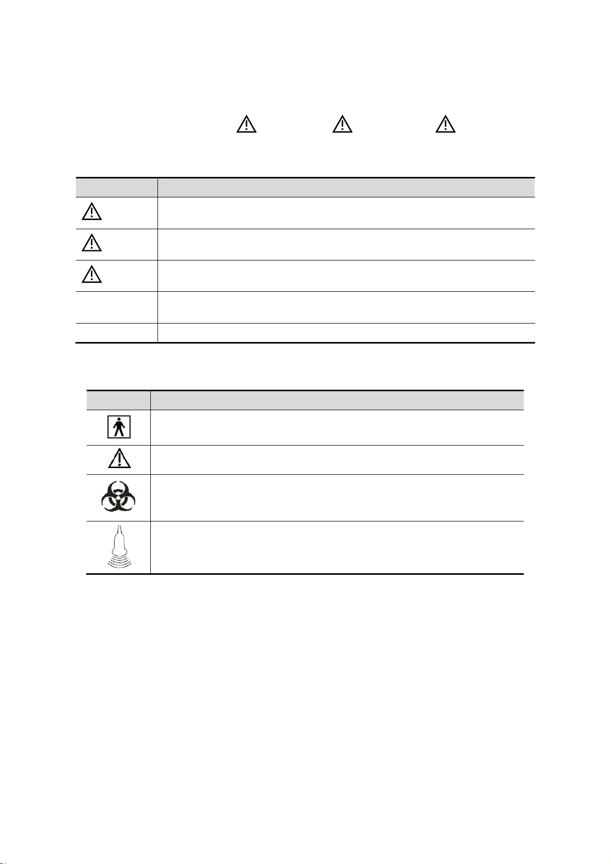
1.3 Meaning of Safety Symbols
Symbol Description
Type-BF applied part.
The ultrasound probes connected to this system are type-BF applied parts.
General warning, caution, risk of danger.
Patient/user infection due to contaminated equipment. Be careful when
performing the cleaning, disinfection and sterilization.
Patient injury or tissue damage from ultrasound radiation. It is required to
practice ALARA when operating ultrasound system.
1-2 Safety Precautions
Page 19

1.4 Safety Precautions
Please observe the following precautions to ensure patient and operator’s safety when using
this system.
DANGER:
WARNING:
Do not operate this system and probes in an atmosphere
containing flammable gasses or liquids such as anesthetic
gasses, hydrogen, and ethanol, because there is danger of
explosion.
1.
Do connect the power plug of this system to wall recept acle s
that meet the ratings indicated on the rating nameplate. If
adapters or multifunctional receptacles are used, it may cause
the leakage current to exceed the safety requirement.
2.
In the environment that patient is 1.5 meters around, conn ect
peripherals to the auxiliary power outlet which i s cap able of
isolation protection, or power the peripherals by auxiliary
output cable or isolation transformer complied with IEC 606011-1 or the power input of the same safety level.
3.
DO NOT use power supply of different phases to power
peripherals, like power supply of air-conditioning.
4.
When using peripherals not powered by the auxiliary output
of the ultrasound system, or using peripherals other than
permitted by Mindray, make sure the overall leakage current
of peripherals and the ultrasound system meets the
requirement of the local medical device electrical regulation
(like enclosure leakage current should be no more than
500uA of IEC 60601-1-1), and the responsibility is held by the
user.
5.
Connect the grounding conductor before turning ON the
system. Disconnect the grounding cable af ter turning OFF the
system. Otherwise, electric shock may result.
6.
For the connection of power and grounding, follow the
appropriate procedures described in this operator’s manual.
Otherwise, there is risk of electric shock. Do not connect the
grounding cable to a gas pipe or water pipe; otherwise,
improper grounding may result or a gas explosion may occur.
7.
Before cleaning the system, disconnect the power cord from
the outlet. Otherwise, system failure and electric shock may
result.
8.
This system is not water-proof. Do not use this system in an y
place where water leakage may occur. If any water is sprayed
on or into the system, electric shock may result. If water is
accidentally sprayed on or into the system, contact Mindray
Customer Service Department or sales represe nt ative.
Safety Precautions 1-3
Page 20

9.
DO NOT use a probe that has a damaged, scratched surface, or
exposed wiring of any kind. Immediately stop using the probe
and contact Mindray Customer Service Dep artment or sa les
representative. There is risk of elect ric shock if using a
damaged or scratched probe.
10.
Do not allow the patient to contact the live parts of the
ultrasound system or other devices, e.g. signal I / O port s.
Electric shock may occur .
11.
Do not use an aftermarket probe other than t hose specified by
Mindray . The probes may damage t he system causing a
profound failure, e.g. a fire in the worst case.
12.
Do not subject the probes to knocks or drops . Use of a
defective probe may cause an electric shock.
13.
Do not open the covers and front panel of the system. Short
circuit or electric shock may result when the system hardware
is exposed and powered on.
14.
Do not use this system when any digit al device such as a highfrequency electrotome, high-frequency therapeutic device or
defibrillator is applied already. Otherwise, there is a risk of
electric shock to the patient.
15.
Only use the ECG leads and PCG transducer provided with the
physiology module; otherwise, electric shock may be resulted.
16.
When moving the system, you should hold the handle;
otherwise, damage may be resulted by abnormal force. Do not
push the system from the left/right side; otherwise, it m ay be
toppled over .
17.
The auxiliary power output outlet in the system is used to
supply power for the recommended peripheral devices. Do not
connect other devices to the outlet, otherwise, the rated out put
power may be exceeded and failure may be resulted. Maximum
output power of the outlet is 240VA (including the auxiliary
output port in the printer compartment).
18.
Accessory equipment (analog or digital) connected to the
ultrasound system must comply with the relevant IEC
standards (e.g., IEC 60950 informa tion technology equipment
safety standard and IEC 60601-1 medical equipment
standard).Furthermore, all configurations must comply wit h the
standard IEC 60601-1-1.It is the resp onsibility of the perso n,
who connects additional equipment to the signal input or
output ports and configures a medical system, to verify that the
system complies with the requirements of IEC 60601-1-1.If y ou
have any questions regarding these requirement s, consult y our
sales representative.
19.
Prolonged and repeated use of keyboards may result in hand or
arm nerve disorders for some individuals. Observe the local
safety or health regulations concerning the use of keyboards.
1-4 Safety Precautions
20.
When using intra-cavity probes, do not activate the probe
outside the p atient’s body .
Page 21

DO NOT touch the Signal I/O ports if in contact with the patient;
21.
otherwise patient injury may result.
CAUTION:
1. Precautions concerning clinical examination techniques:
This system must be used only by qualified medical
professionals.
This operator’s manual does not describe clinical examination
techniques. The clinician should select the proper examination
techniques based on specialized training and clinical
experience.
2. Malfunctions due to radio wave:
If a radio wave emitting device is used in the proximity of this
system, it may interfere with operations. Do not use or take any
devices transmitting RF signals (such as cellular phones,
transceivers and radio controlled products) in the room placing
the system.
If a person brings a device that generates radio waves near the
system, ask him / her to immediately turn OFF the device.
3. Precautions concerning movement of the system:
Please install the system on a flat plane with casters locked.
Otherwise, damage may be resulted by accidental moving.
Do not move the system laterally, which may result in damage in
case of toppling.
Move the system slowly on the slope by two people, otherwise,
damage may result in case of unexpected sliding.
Do not sit on the system, which may result individual falling in
case of system moving.
Object placed on the monitor may fall and injure an individual.
Fasten and fully secure any peripheral device before moving the
system. A loose peripheral device may fall and injure an
individual.
When move the system on the steps, please take care to prevent
the system from toppling.
4. If the circuit protector is tripped, it indicates that the system or a
peripheral device was improperly shut down and the system is
unstable. You cannot repair the system under this circumstance
and must call the Mindray Customer Service Department or
sales representative.
5. There is no risk of high-temperature burns during normal
ultrasound examinations. It is possible for the surface
temperature of the probe to exceed the body temperature of a
patient due to environmental temperature and exam type
combinations. Do not apply the probe to the same region on the
patient for a long time. Apply the probe only for a period of time
required for the purpose of diagnosis.
6. Do not use the system to examine a fetus for a long period of
time.
Safety Precautions 1-5
Page 22

7. The system and its accessories are not disinfected or sterilized
prior to delivery. The operator is responsible for the cleaning
and disinfection of probes and sterilization of biopsy brackets
according to the manuals, prior to the use. All items must be
thoroughly processed to completely remove harmful residual
chemicals, which will not only be harmful to the human body,
but also damage the accessory.
8. It is necessary to press <End Exam> to end the current scan
that is in progress and clear the current Patient Information
field. Otherwise, new patient data may be combined with the
previous patient data.
9. Do not connect or disconnect the system’s power cord or its
accessories (e.g., a printer or a recorder) without turning OFF
the system power first. This may damage the system and its
accessories or cause electric shock.
10. If the system is powered off improperly during operation, it may
result in data damage of the system hard disk or system failure.
11. Do not use a USB memory device (e.g., a USB flash drive,
removable hard disk) which has unsafe data. Otherwise, system
damage may result.
12. It is recommended to only use the video devices specified in
this manual.
13. Do not use gel, disinfectant, probes, probe sheath or needleguided brackets that are not compatible with the system.
14. Read the Acoustic Output Principle in the operation manual
carefully before operating this system on clinical examination.
15. The cover contains natural rubber that can cause allergic
reactions in some individuals.
NOTE: 1. DO NOT use the system in the vicinity of strong electromagnetic field (such as
2. Do not use the system in the vicinity of high-frequency radiation source (e.g.
3. When using or placing the system, keep the system horizontal to avoid
4. To avoid damaging the system, do not use it in following environment:
16. Please use the ultrasound gel compliant with the relevant local
regulations.
17. Normal operation may be affected by unstable mains power
supply; it is recommended that our product be powered from an
uninterruptible power supply.
a transformer), which may affect the performance of the system.
cellular phones), which may affect the performance of the system or even lead
to failure.
imbalance.
z Locations exposed to direct sunlight;
z Locations subject to sudden changes in environmental temperature;
z Dusty locations;
z Locations subject to vibration;
z Locations near heat generators;
z Locations with high humidity.
1-6 Safety Precautions
Page 23

5. Turn ON the system only after the power has been turned OFF for a while. If the
system is turned ON immediately after being turned OFF, the system may not be
rebooted properly and could malfunction.
6. Press <Freeze> key to freeze an image or turn off the power of the system
before connecting or disconnecting a probe. Otherwise, the system and/or
probe can be damaged.
7. Remove the ultrasound gel from the face of the probe when the examination is
completed. Water in the gel may enter the acoustic lens and adversely affect
the performance and safety of the probe.
8. You should properly back up the system to a secure external storage media,
including system configuration, settings and patient data. Data stored to the
system’s hard drive may be lost due to system failure, improper operation or
accident.
9. Do not apply external force to the control panel. Otherwise, the system may be
damaged.
10. If the system is used in a small room, the room temperature may rise. Please
provide proper ventilation and free air exchange.
11. To dispose of the system or any part, contact Mindray Customer Service
Department or sales representative. Mindray is not responsible for any system
content or accessories that have been discarded improperly. Mindray is not
responsible for any system content or accessories that have been discarded
improperly.
12. Electrical and mechanical performance may be degraded due to long usage
(such as current leakage or distortion and abrasion); the image sensitivity and
precision may become worse too. To ensure optimal system operations, it is
recommended that you maintain the system under a Mindray service
agreement.
13. The replaceable fuse is inside the chassis. Refer replacing job to Mindray
service engineers or engineers authorized by Mindray only.
14. Do not turn OFF the power supply of the system during printing, file storage or
invoking other system operations. An interrupted process may not be
completed, and can become lost or corrupted.
15. The iScape feature constructs a single extended image from a series of
individual image frames. The quality of the final image is user-dependent and
requires skill to efficiently apply the feature and technique. Exercise caution
when measurements are performed from an iScape image.
16. Ensure that the current exam date and time are the same as the system date
and time.
Please read the following precautions carefully to ensure the safety of the patient and the
operator when using the probes.
WARNING:
1. The probe is only for use with the specified ultrasonic
diagnostic system. Please refer to the “2.5.2 Probes Available” to
select the proper probe.
2. The ultrasonic probe must be used only by qualified
professionals.
3. Confirm that the transducer and probe cable are normal before
and after each examination. A defective probe may cause
electric shock to the patient.
Safety Precautions 1-7
Page 24

4. Do not subject the probe to shock. A defective probe may cause
electric shock to the patient.
CAUTION:
5. Do not disassemble the probe to avoid the possibility of electric
shock.
6. Never immerse the probe connector into liquids such as water
or disinfectant because the connector is not waterproof.
Immersion may cause electric shock or malfunction.
7. A probe sheath must be installed over the probe before
performing intra-cavity or intra-operative examination.
1. When using the probe, wear sterile gloves to prevent infection.
2. Be sure to use sterile ultrasound gel. Please use the ultrasound
gel compliant with the relevant local regulations. And manage
the ultrasound gel properly to ensure that it does not become a
source of infection.
3. In normal diagnostic ultrasound mode, there is no danger of a
normal-temperature burn; however, keeping the probe on the
same region of the patient for a long time may cause such a
burn.
4. Do not use the carrying case for storing the probe. If the carrying
case is used for storage, it may become a source of infection.
5. It is required to practice ALARA when operating ultrasound
system. Minimize the acoustic power without compromising the
quality of images.
6. The probe and accessories supplied with it are not delivered
disinfected or sterilized. Sterilization (or high-level disinfect)
before use is required.
7. Disposable components should be packaged sterile and for
single-use only. Do not use if integrity of packaging violated or if
expiration date has passed. Please use the disposable
components compliant with the relevant local regulations.
8. Please use the disinfection or sterilization solution
recommended in this operator’s manual; otherwise Mindray will
not be liable for damage caused by other solutions. If you have
any questions, please contact Mindray Customer Service
Department or sales representative.
9. Do not use pre-lubricated condoms as a sheath. Lubricant may
not be compatible with the probe material and damage may
result.
10. The damage of the probe may be caused by the contact of
improper gel or cleaner:
z DO NOT soak or saturate probes in the strong polar solution
of ethanol, chloride of lime, ammonium chloride, acetone or
formaldehyde.
z DO NOT contact the probe with solutions or ultrasound gels
containing oily medium such as mineral oil or lanoline.
1-8 Safety Precautions
Page 25

NOTE: Read the following precautions to prevent the probe from malfunction:
z Before connecting or disconnecting the probe, freeze or turn off the
diagnostic ultrasound system.
z Clean and disinfect the probe before and after each examination.
z After the examination, wipe off the ultrasound gel thoroughly. Otherwise,
the ultrasound
Ambient conditions:
1. To prevent the probe from being damaged, do not use it where it will be
exposed to:
z Direct sunlight or X-rays
z Sudden changes in temperature
z Dust
z Excessive vibration
z Heat generators
2. Use probes under the following ambient conditions :
z ambient temperature: 0°C to 40°C
z relative humidity: 30% to 85% (no condensation)
z atmospheric pressure: 700 hPa to 1060 hPa
3. Use D7-2E probes under the following ambient conditions :
z ambient temperature: 10°C to 40°C
z relative humidity: 30% to 85% (no condensation)
z atmospheric pressure: 700 hPa to 1060 hPa
Repeated disinfection will eventually damage the probe, please check the probe
performance periodically.
gel may solidify and the image quality would be degraded.
1.5 Latex Alert
When choosing a probe sheath, it is recommended that you directly contact CIVCO for
obtaining probe sheath, pricing information, samples and local distribution information. For
CIVCO information, please contact the following:
CIVCO Medical Instruments
Tel: 1-800-445-6741
WWW.civco.com
WARNING:
Allergic reactions in latex (natural rubber) sensitive patients may
range from mild skin reactions (irritation) to fatal anaphylactic
shock, and may include difficulty in breathing (wheezing),
dizziness, shock, swelling of the face, hives, sneezing or itching
of the eyes (FDA Medical Alert on latex products, “Allergic
Reactions to Latex-containing Medical Devices”, issued on March
29, 1991).
Safety Precautions 1-9
Page 26
1.6 Warning Labels
The warning labels are attached to this system in order to call your attention to potential
hazards. The symbol on the warning labels indicates safety precautions.
The warning labels use the same signal words as those used in the operator’s manual. Read
operator’s manual carefully before using the system.
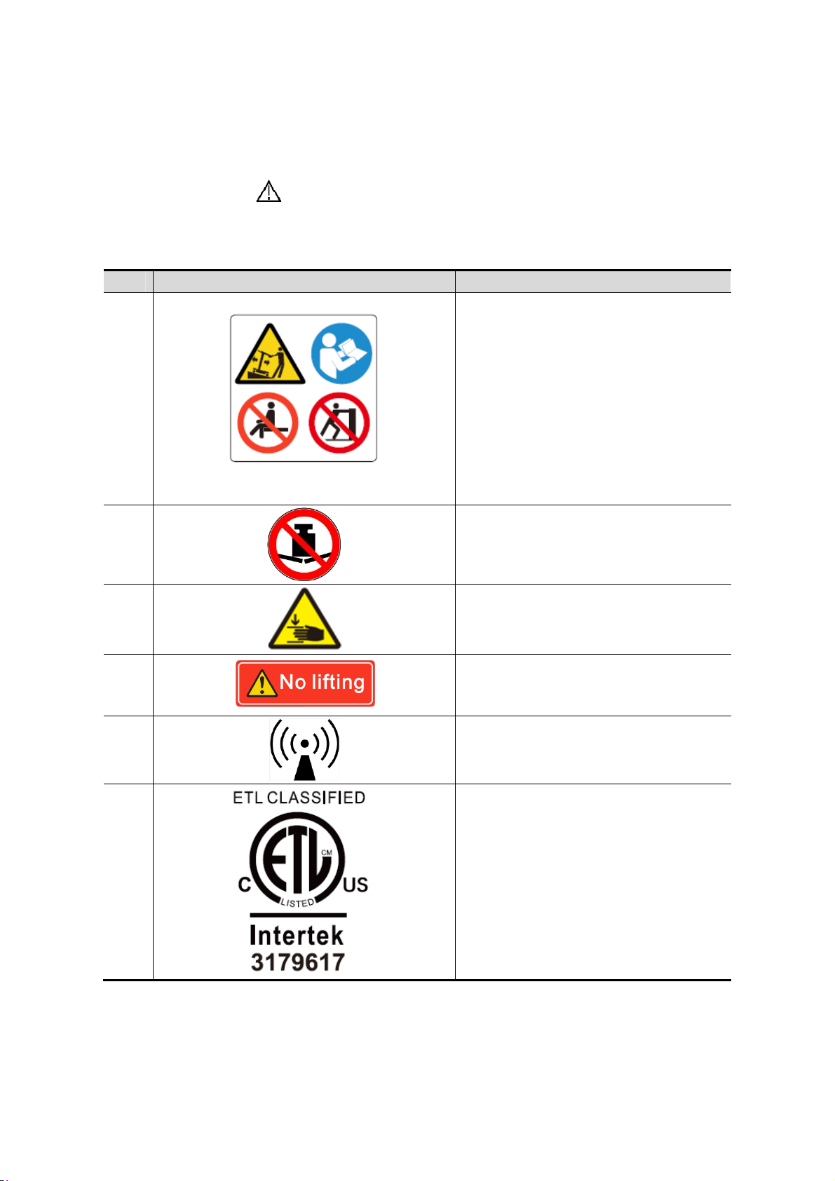
The name, pattern and meaning of each warning label are described as follows:
No. Warning Labels Meaning
1.
a
b
d
c
a. Do not place the system on a sloped
surface. Otherwise the system may
slide, resulting in personal injury or the
system malfunction. Two persons are
required to move the system over a
sloped surface.
b. Do not sit on the system.
c. DO NOT push the system when the
casters are locked.
d. Please carefully read this manual
before use system.
2.
3.
4.
5.
6.
Beware of excessive stress exerted to
the system.
Mind your hands.
Please do not lift the hanger or try to
push the ultrasound system by using it.
Non-ionizing radiation
CONFORMS TO AAMI STD 60601-1,
IEC STD 60601-2-37,IEC STD 606012-18;
CERTIFIED TO CSA STD C22.2 NO.
60601-1, 60601-2-37, 60601-2-18
1-10 Safety Precautions
Page 27

2 System Overview
2.1 Intended Use
The Diagnostic Ultrasound System is intended for adults, pregnant women, pediatric
patients and neonates.It is intended for use in fetal, abdominal, pediatric, small organ(breast,
thyroid, testes), neonatal cephalic,adult cephalic,trans-rectal, trans-vaginal, musculoskeletal(conventional), musculo- skeletal(superficial), cardiac adult, cardiac pediatric and
peripheral vessel exams.
2.2 Contraindication
This system is not intended for ophthalmic use.
2.3 Product and Model Code
DC
-
Model code
Product code
NOTE: The functions described in the operator’s manual may vary depending upon the
specific system you purchased.
2.4 Product Specifications
2.4.1 Imaging Mode
B Mode B
M Mode M
Color M Mode (CM)
C Mode Color
D Mode PW Doppler
CW Doppler
Power(Dirpower)
System Overview 2-1
Page 28

Special
Imaging
Elastography
Tissue Doppler Imaging
TDI QA
iScape View
Free Xros M/Free Xros CM
3D/4D
Smart 3D
Static 3D
iPage
iLive
2.4.2 Power supply
Voltage
Frequency 50/60Hz
Power
consumption
Fuse 250V~ T10AH
100-240V~
600VA
2.4.3 Environmental Conditions
Operational Conditions Storage and Transportation
Conditions
Ambient
temperature
Relative
humidity
Atmospheric
pressure
WARNING:
10℃~40℃ -20℃~55℃
30%~85% 30%~95%
700hPa~1060hPa 700hPa~1060hPa
Do not use this system in the conditions other than those
specified.
2-2 System Overview
Page 29

2.4.4 Size and Weights
External dimensions:
z 812mm (L)X600mm (W)X1331 (1515)mm (H)
Net weight: 130.87Kg (without the battery)
2.5 System Configuration
2.5.1 Standard Configuration
Main unit
Accessories
z Operator's manuals
z Ultrasound gel
z Dust-proof cover
z Probe ports dust-proof cover
z Tray assembly
z Left bracket for the intra-cavity probe
z Right bracket for the intra-cavity probe
z Probe holder
z Probe holder for pencil probe
z Cables
z Grounding cable
z Multilingual controls overlay
2.5.2 Probes Available
No. Probe Model Intended Use Region Applied
3C5A Fetal, Abdominal, Pediatric, Neonatal
1.
7L4A Abdominal, Pediatric, Small Organ
2.
3. L7-3
4. D7-2E Fetal, Abdominal Abdomen
5. L14-6NE
Cephalic, Musculo-skeletal
(Conventional), Peripheral vessel
(breast, thyroid, testes), Neonatal
Cephalic, Musculo-skeletal
(Conventional), Musculo-skeletal
(Superficial), Peripheral vessel
Abdominal, Pediatric, Small Organ
(breast, thyroid, testes), Neonatal
Cephalic, Musculo-skeletal
(Conventional), Musculo-skeletal
(Superficial), Peripheral vessel
Pediatric, Small Organ (breast, thyroid,
testes), Musculo-skeletal
(Conventional), Musculo-skeletal
(Superficial), Peripheral vessel
Body surface
Body surface
Body surface
Body surface
6. V11-3 Fetal, Trans-rectal, Trans-vaginal Intracavitary
System Overview 2-3
Page 30

No. Probe Model Intended Use Region Applied
7. P4-2
Abdominal, Adult Cephalic, Cardiac
Adult, Cardiac Pediatric
Body surface
Some of the probes have matched needle-guided brackets for biopsy, the available probes
and the corresponding needle-guided brackets are listed as follows:
NGB-004
V11-3
Metal/needle un-detachable
/ 16G, 17G, 18G
Plastic/needle detachable:
3C5A
NGB-006 (plastic/needle
detachable, metal/needle
detachable)
25°, 35°, 45°
13G, 15G, 16G, 18G, 20G;
Metal/needle detachable:
14G, 16G, 18G, 20G, 22G
Metal/needle detachable:
14G, 16G, 18G, 20G, 22G;
Plastic/needle detachable:
13G, 15G, 16G, 18G, 20G
7L4A/L14-6NE/
L7-3
NGB-007
plastic/needle detachable
metal/needle detachable
40°, 50°, 60°
NGB-011
P4-2
11°, 23° 13G, 15G, 16G, 18G, 20G
metal/needle un-detachable
2.5.3 Options
No. Item
1 ECG module (including ECG lead)
2 DC-IN cable (configured with ECG module)
3 Ultrasound gel warmer
4 4D module
5 CW module
6 Buit-in battery
7 Built-in Wireless Adapter
8 Pencil probe port
9 Footswitch: (two-pedal/three-pedal)
10 1D barcode reader
11 Nerve Package
12 Emergency&Critical Package
13 Application
software
14 IVF
package
15 Smart OB
IMT
16 Smart NT
17 Smart Bladder
18 Tissue Doppler Imaging
19 iScape View
2-4 System Overview
Page 31

No. Item
20 Free Xros M
21 Free Xros CM
22 Smart 3D
23 Static 3D
24 4D
25 iPage (configured with 4D module)
26 Elastography Imaging
27 iLive (configured with 4D module or Smart 3D)
28 TDI QA (configured with TDI)
29 iScanHelper
30
31 DICOM Worklist
32 DICOM MPPS
33 DICOM Query/Retrieve
DICOM Basic
DICOM Basic should be configured first.
34
35
36
DICOM
DICOM OB/GYN
Structured Report
DICOM Vascular
Structured Report
DICOM Cardiac
Structured Report
2.5.4 Peripherals Supported
No. Item Model
1. Graph / text printer
Digital Color Video
2.
Printer
Digital Black and White
3.
Video Printer
HP Deskjet Ink Advantage 2020hc
HP Officejet Pro 8100
SONY UP-D23/25MD
SONY UP-D897
Analog Black and White
4.
Video Printer
MITSUBISHI P93W-Z
SONY UP-X898MD
5. Bar code reader LS2208
6. Footswitch
971- SWNOM (two-pedal or three-pedal)
FS-81-SP-2 (one-pedal)
Parts that can be used within patient environment:
z Main unit.
z Probes.
z Footswitch.
z Printers: HP Deskjet Ink Advantage 2020hc, HP Officejet Pro 8100, SONY UP-
D23/25MD, SONY UP-D897, MITSUBISHI P93W-Z, SONY UP-X898MD.
System Overview 2-5
Page 32
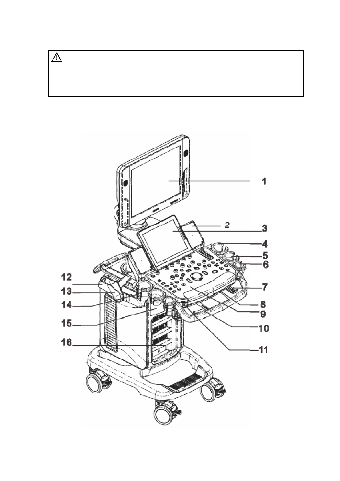
WARNING:
This system complies with IEC60601-1-2:2007, and its RF
emission meets the requirements of CISPR11 Class B. In a
domestic environment, the customer or the user should
guarantee to connect the system with Class B peripheral devices;
otherwise RF interference may result and the customer or the
user must take adequate measures accordingly.
2.6 Introduction of Each Unit
2-6 System Overview
Page 33
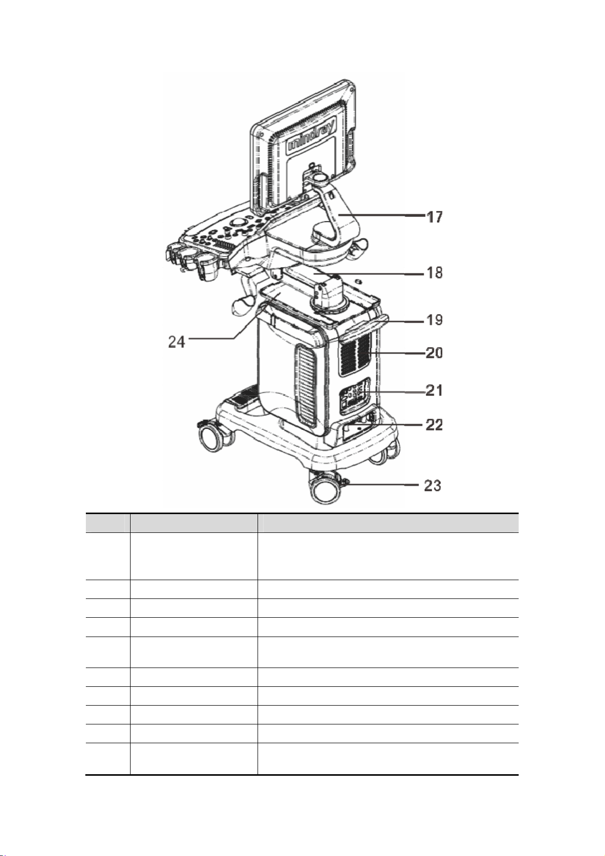
No. Name Function
Displays the images and parameters during
1. Monitor
2. Speaker Sound output.
3. Touch screen panel Operator-system interface or control.
4. Ultrasound gel holder Used for placing the ultrasound gel.
scanning.
(Support optional 15-inch/ 17-inch/ 19-inch monitor)
5. Probe holder
6. Pencil probe holder Used for placing the pencil probe.
7. Probe cable hook Used for fixing the probe cable.
8. Keyboard Used for typing characters or entering some functions.
9. Main control panel Operator-system interface or control.
10.
Control panel adjusting
lever
Used for placing the general probe (not including pencil
probe or intra-cavity probe).
Used for lifting or swiveling the control panel.
System Overview 2-7
Page 34

No. Name Function
11. USB USB port
12. Hanger /
13. Intracavitary probe holder Used for fixing the intracavitary probe.
14.
15. Physio panel
16. Probe port Sockets connecting transducers and the main unit.
17. Monitor supporting arm
18.
19. Rear handle Used for pushing and moving the system.
20. Cooling vent /
21. I/O Panel
22.
23.
24.
Ultrasound gel holder/gel
warmer
Control panel supporting
arm
Power supply panel
Caster lock
Tray
Used for placing the ultrasound gel or installing the gel
warmer.
Used for connecting the ECG leads and external ECG
device.
Supports the monitor, for adjusting the height and
position of the monitor.
Supports the control panel, for adjusting the height of
the panel.
Interface panel used for inputting and outputting
signals.
Electrical port panel.
Lock the caster. The device keeps stable when four
casters are locked.
Place the stuff or peripherals.
NOTE: Do not overexert to push down or lift up the control panel when operate the control
table adjusting handle.
2-8 System Overview
Page 35
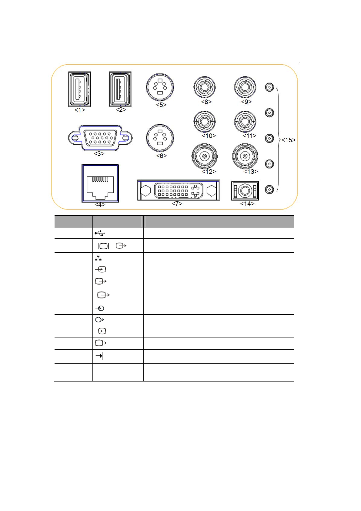
2.7 I/O Panel
No. Symbol Function
<1><2>
<3>
<4>
<5>
<6>
<7>
<8><9>
<10><11>
<12>
<13>
<14>
<15>
Malfunction
indication lights
USB port, used for connecting USB devices.
VGA signal output; connects a monitor or projector.
Ethernet interface.
Separate video input (reserved).
Separate video output.
DVI signal output.
Audio signal input port, left channel(reserved).
Audio signal output port, right channel.
Used for
Used for
Remote interface for connecting video printer.
Indicate the system’s malfunction.
composite video input (reserved).
composite video output.
System Overview 2-9
Page 36
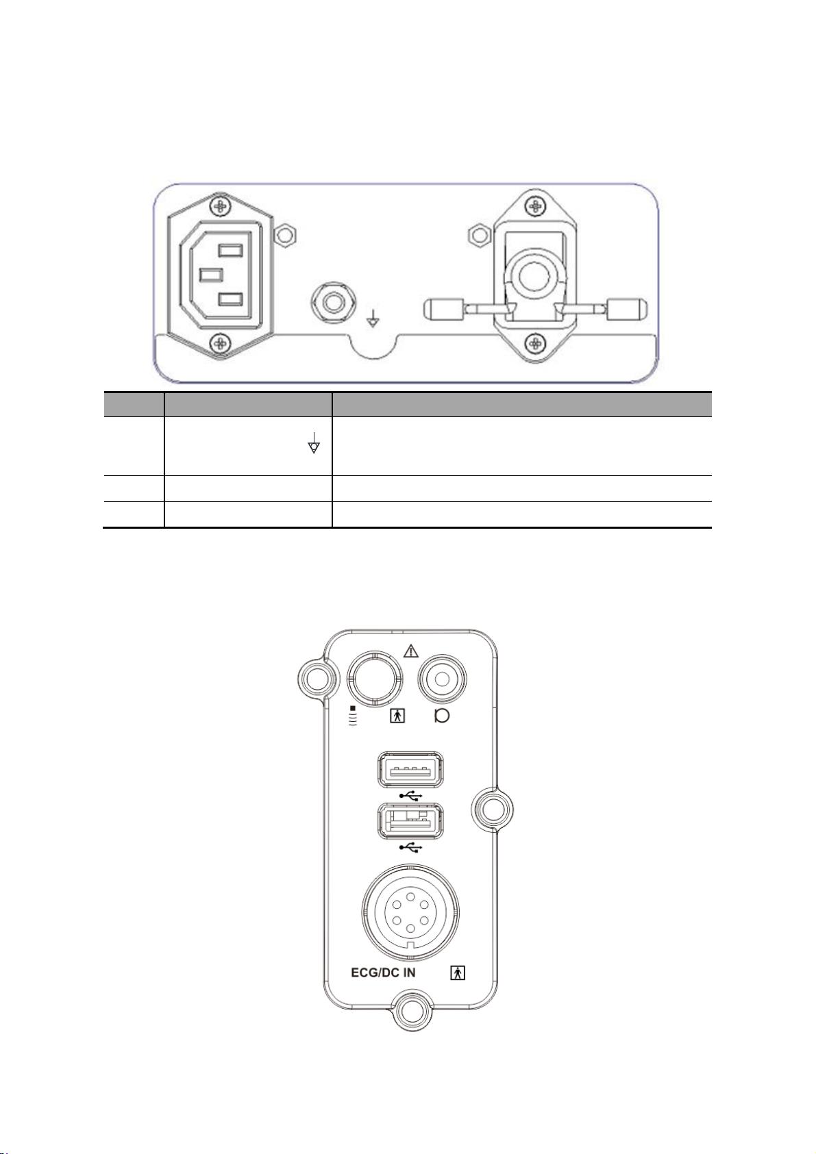
2.8 Power Supply Panel
<2>
<1>
No. Name Function
Used for equipotential connection, balancing the
<1>
<2> AC Auxiliary Output Power supply port for peripherals.
<3> AC Input AC power inlet.
Equipotential terminal
protective earth potentials between the system and other
electrical equipment.
2.9 Physiological-signal Panel
<3>
<1>
<2>
<3>
<4>
2-10 System Overview
Page 37
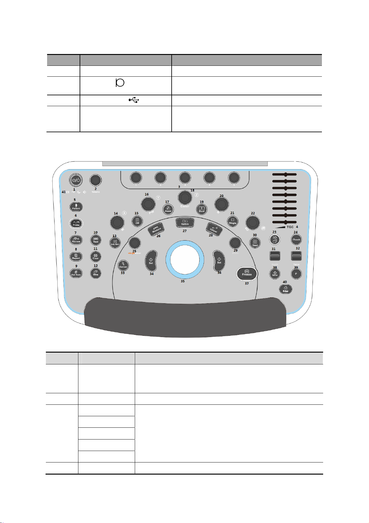
No. Name Function
<1> Pencil probe port Pencil probe port (reserved).
<2>
<3> Two USB ports Used for connecting USB devices.
<4> ECG lead signal input
Mic In port
port/external ECG signal input
port
Use for connecting microphone to record vocal
comments (reserved)
Connects to ECG leads, to directly obtain patient
electrocardiosignal/used for connecting the signal
output port of ECG monitor.
2.10 Control Panel
No. English Name Description
Power button
1.
2.
3.
4.
/
Volume Adjust the volume.
/
/
/
/
/
TGC Slide to adjust the depth gain.
Press the button to turn on the system, the system enters the
work status and the indicator becomes green.
Adjust the corresponding functions on the touch screen.
System Overview 2-11
Page 38

No. English Name Description
5.
6.
7.
8.
9.
10.
11.
12.
13.
14.
15.
16.
17.
Patient Enter/exit Patient Info screen.
Probe Switch probe and exam mode.
Review Review the stored images.
Report Open/close the exam report.
End Exam End the current exam.
Text Enter/exit the textual comment status.
Clear Clear the comments or measurement caliper.
Cine
Body Mark Enter/exit Body Mark.
M
CW Enter CW mode.
PW
Power Enter Power mode.
Press to enter the Cine Review status from non-cine status
when there is a multi-frame cine file playing.
Press to enter M mode, and rotate to adjust M mode gain.
While in 3D/4D mode, rotate the knob to make the 3D image to
rotate around X-axis.
Press to enter PW mode, and rotate to adjust PW or CW gain.
While in 3D/4D mode, rotate the knob to make the 3D image
rotate around Y-axis.
18.
19.
20.
21.
22.
23.
24.
25.
26.
27.
28.
29.
Press to enter Color mode, and rotate to adjust Color or Power
Color
Dual
B Press to enter B mode, and rotate to adjust B mode gain.
Single Enter single window in multiple window mode.
4D
3D Enter the 3D imaging function: Smart 3D or Static 3D.
iTouch Optimize the image.
Angle/Steer
Measure Enter/exit the application measurement mode.
Update
Caliper Enter/exit the general measurement mode.
Zoom
gain. While in 3D/4D mode, rotate the knob to make the 3D
image rotate around Z-axis.
Enter Dual mode in Non-Dual mode.
Switch between the two display windows in the Dual mode.
Press to enter 4D function and rotate to make the 3D image
rotate.
Adjust the angle.
Adjust the steering of the probe.
Switching key: Press to change the currently active window.
Start/stop image acquisition in iScape or 3D/4D mode.
Rotate to enter the pan-zoom mode, and press to enter the
spot-zoom mode.
30.
31.
2-12 System Overview
Quad
Depth Adjust the depth in real-time imaging.
Enter Quad mode in Non-Quad mode.
Switch between the four display windows in the Quad mode.
Page 39
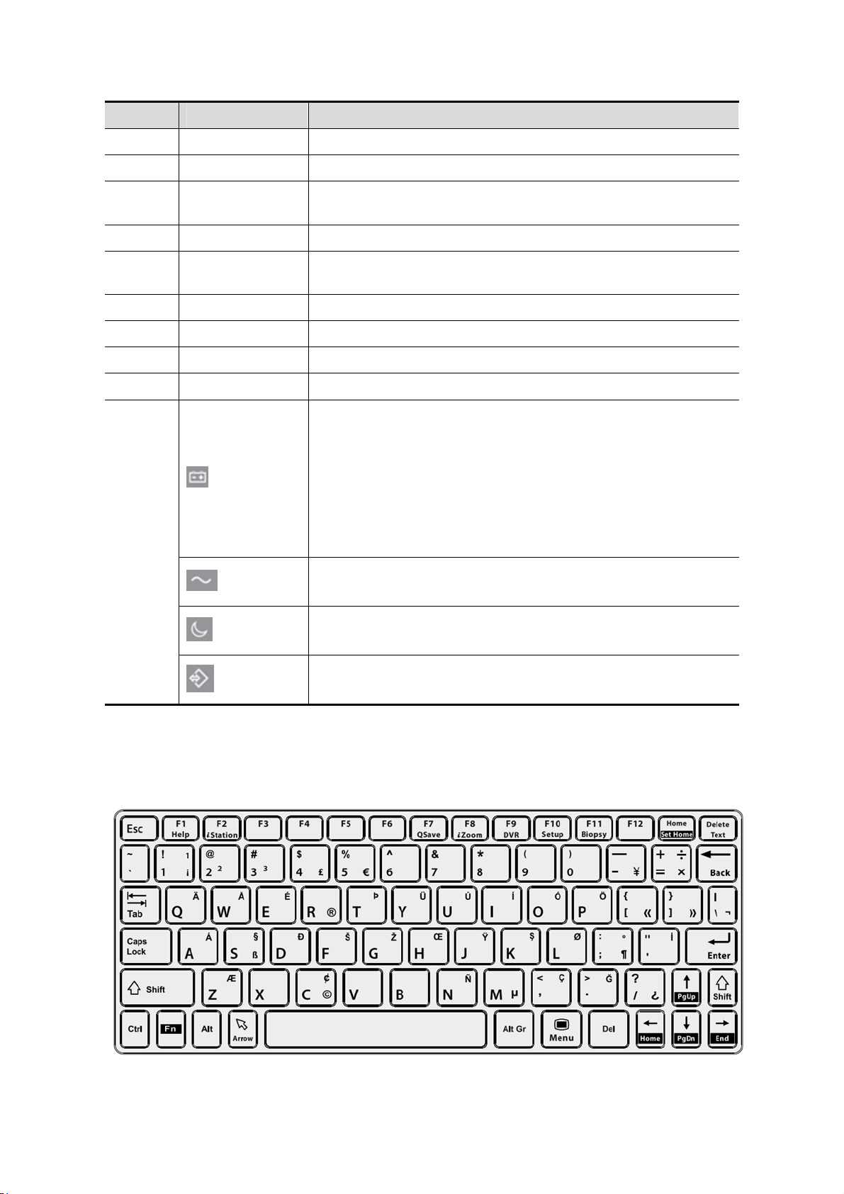
No. English Name Description
32.
33.
34.
35.
36.
37.
38.
39.
40.
41.
Focus Change the focus position.
Cursor Show/hide the cursor.
Set
Confirm an operation. The function is same with the left-button
of the mouse.
/ Move the trackball to change the cursor position.
Set
Confirm an operation. The function is same with the left-button
of the mouse.
Freeze Freeze/defreeze the image.
Save Save the image; user-defined key.
P User-defined keys, functions of which can be defined in preset.
Print Print: user-defined key.
Battery status indicator.
Charging status:
It illuminates in green when batteries are charged fully.
Discharging status:
It illuminates in green color when the power of the batteries is
more than 20%;
It illuminates in orange color for low battery power.
AC indicator
The indicator is on at AC supply.
Standby indicator.
Standby: blinking in orange.
Hard disk status indicator.
The indicator blinks in green when hard disk is running.
NOTE: “/” means the key are undefined or have no silk print. For the undefined keys, you
can customize them.
Keyboard
System Overview 2-13
Page 40

Common functional keys
No. Key Function
1. Enter
Confirm the entered data, or move the cursor to the top of
the next row of the text or input field.
2. Esc Cancel the operation or exit.
3. Tab Jump to the next operable item.
4. Back space Insert a space.
5. Caps Lock Switch between upper/lowercase.
6. Home
Activate the Home function: return to start position of the
comment.
7. Delete Text Delete all comments on the screen.
8. Direction-control keys
Move the cursor one letter each time, or, select the
surrounding objects in the selectable area.
9. Del Delete the character after the cursor
10. Back Space Delete the character before the cursor
Functions of the F1 to F12 keys
No. Key Function
1 F1 Help Open or close the accompanying help documents.
2 F2 iStation Enter or exit the Patient Info system.
3 F3~F6 User-defined keys, the functions of which can be preset.
4 F7 QSave Save the current image parameters quickly.
5 F8 iZoom Enter/exit full-screen zoom status.
6 F9 DVR Reserved, enter/exit DVR mode.
7 F10 Setup Enter/exit Setup.
8 F11 Biopsy Display/hide the guide line.
9 F12 User-defined keys, the functions of which can be preset.
Functions of key combinations
The system supports multi-language input using key combinations. Key combinations
include [Shift], [Alt Gr], [Ctrl], [Fn] and some alphabet keys. For details about switching
the system to multi-language, see “12.1.1 Region” for details.
z <Shift> key
<Shift> + key: enter the top left letter on the key.
For the alphabet keys (<A>~<Z>), press <Shift> + key to enter the current letter in a
different case.
z [Alt Gr] key
Combined with other letter keys, [Alt Gr] can be used for entering other languages.
Press [Alt Gr] and a letter key simultaneously. The letter in the top-right corner of the
key is entered.
z [Ctrl] key combined keys
On the iStation or Review screen, use <Ctrl> and <Set> to select more than one
patient or more than one image.
z [Fn] key
2-14 System Overview
Page 41

For these combination keys, press <Fn> + key to use the functions indicated with a frame
on the key.
No. Fn+ Name Function
1.
→
2.
←
3.
↑
4.
↓
5. Home
End
Home Home
Pg Up Turn pages upward.
Pg Dw Turn pages downward.
Set
Home
Move the cursor to the end of the row, or the rightmost side of an
editable unit.
Activate the Set Home function: set the start point of a comment.
System Overview 2-15
Page 42

2.11 Symbols
This system uses the symbols listed in the following table, and their meanings are explained
as well.
No. Symbol Description
1
2
3
4
5
6
7
8
9
10
11 S-VIDEO
12
VGA
DVI-D
Type-BF applied part
Refer to the relevant content in the Operator’s Manual, to avoid
safety incidents
AC (Alternating current)
Equipotentiality
Power button
Foot switch
Transducer sockets
Network port
USB port
Used for VGA output.
Reserved, used for separate video output
Separate video input, reserved.
DVI-D signal output
13
14
15
16
17
18
19
20
21
22
AUDIO
Used for stereo audio output
Used for stereo audio input
Battery Status Indicator
Hard disk status indicator
Standby status indicator
AC power supply status indicator
Microphone input jack
Dangerous voltage
Product serial number
Manufacture date
2-16 System Overview
Page 43

3 System Preparation
1.
WARNING:
Do not connect the three-wire cable of the system with
a two-wire plug without protective grounding;
otherwise, electric shock may result.
2.
Do connect the power plug of this system to wall
receptacles that meet the ratings indicated on the
rating nameplate. If adapters or multifunctional
receptacles are used, it may cause the leakage current
to exceed the safety requirement.
3.
In the environment that patient is 1.5 meters around,
connect peripherals to the auxiliary power outlet
which is capable of isolation protection, or power the
peripherals by auxiliary output cable or isolation
transformer complied with IEC 60601-1-1 or the power
input of the same safety level.
4.
DO NOT use power supply of different phases to
power peripherals.
5.
When using peripherals not powered by the auxiliary
output of the ultrasound system, or using peripherals
other than permitted by Mindray, make sure the overall
leakage current of peripherals and the ultrasound
system meets the requirement of the local medical
device electrical regulation (like enclosure leakage
current should be no more than 500uA of IEC 60601-1-
1), and the responsibility is held by the user.
3.1 Move/Posit the System
Please read and understand the safety precautions before placing the system to ensure
safety for both operator and device.
1. Switch off the power, unplug the power cord.
2. Disconnect all cables from the off-board peripheral devices (printer, recorder, etc.).
3. Release the four casters, and move the system by holding the handle.
4. When you move the system to a desired location, lock the four casters.
5. Leave at least 20cm at the back and both sides of the system.
CAUTION:
1. Maintain a generous – free air flowing space around the
back and both sides of the system; failure may result due to
increased rise in system operating temperature.
2. Pay extra attention when moving the system on a sloping
ground, DO NOT move it on a more than 10°-sloped plane to
avoid system toppling.
System Preparation 3-1
Page 44

3.2 Power Supply
This system can work normally only when it is connected to the external power supply or
the battery capacity is sufficient.
3.2.1 Connecting AC Power Supply
The connection method is described as follows:
1. Push the retaining clamp upward, and insert the power plug into the receptacle, as
shown in the figure below.
Retaining clamp
Power plug
2. Push the retaining clamp downward, and lock the power cord, as shown in the figure
below.
3. Plug the other end power plug into an appropriate power socket. The grounding
terminal should be connected with a power grounding cable to ensure that protective
grounding works normally.
NOTE: Make sure to allow sufficient slack in the cable so that the plug will not be
pulled out from the socket even if the system is moved slightly. If the plug is
pulled out accidentally, data may be lost.
3-2 System Preparation
Page 45

3.2.2 Powered by Batteries
When connected to the external AC power supply, the system is powered by the
external power. The lithium ion batteries inside it are in the charging status.
When disconnected from the external power supply, the system is powered by the
lithium ion batteries. Refer to Chapter 15 for the detailed operations and precautions.
3.2.3 Equipotential Terminal
The symbol represents the equipotential terminal that is used for balancing the
protective earth potentials between the system and other electrical equipment. For the
equipotential terminal location, please refer to “2.8 Power Supply Panel”.
1.
WARNING:
Be sure to connect the equipotential wire before
inserting the power plug into the receptacle; be sure
to remove the power plug from the receptacle before
disconnecting the equipotential wire; otherwise
electric shock may result.
2.
When you connect another device to this system, you
should use the equipotential wire to connect each of
equipotential terminals; otherwise electric shock may
result.
3.
Connect the earth cable before turning ON the
system. Disconnect the earth cable after turning OFF
the system. Otherwise, electric shock may result.
4.
DO NOT connect this system to the outlets with the
same circuit breakers and fuses that control the
current to devices such as life-support systems. If
this system malfunctions and generates over-current,
or when there is an instantaneous current at power
ON, the circuit breakers and fuses of the building’s
supply circuit may be tripped.
3.3 Power ON/OFF
3.3.1 Powering ON the System
CAUTION:
To ensure safe and effective system operation, you must
perform daily maintenance and checks.
If the system begins to function improperly – immediately
stop scanning. If the system continues to function improperly
– fully shut down the system and contact Mindray Customer
Service Department or sales representative.
If you use the system in a persistent improperly functioning
state – you may harm the patient or damage the equipment.
System Preparation 3-3
Page 46

Checking before Power ON
To check the system before the system is turned on:
No. Check Item
The temperature, relative humidity and atmospheric pressure shall meet the
<1>
<2> There shall be no condensation.
<3>
<4> There shall be no loose screws on the monitor or control panel.
requirements of operating conditions. See "2.4.3 Environmental Conditions" for
details.
There shall be no distortion, damage or dirt on the system and peripheral
devices.
If any dirt is found, cleaning shall be performed as defined in section “16 System
Maintenance”.
<5>
<6> The probes and probe cables shall be free of damage or stains.
<7>
<8>
<9>
<10> The overall scanning environment and field must be clean.
<11> The locking mechanism of casters can work normally.
Turning on the Power
There shall be no cable damage (e.g. power cord). Maintaining secure
connections to the system at all times.
No miscellaneous odds and ends are allowed to be attached or affixed to the
control panel.
Ensure that all connections are free from damage and remain clear of foreign
object blockages.
There shall be no obstacles around the system and its air vent.
Probe cleaning and disinfection. (Please refer to “13 Probes and Biopsy” for
details).
To turn on the system:
(1) Press the power button
(2) The system enters the work status.
in the upper left corner on the control panel.
When the battery capacity is sufficient, you can also press the power button
directly to turn on the system.
To check the system after the system is turned on:
No. Check Item
<1> There shall be no unusual sounds or smells indicating possible overheating.
<2> There shall be no persistently displayed system error message.
<3>
<4>
<5> The control panel keys and knobs are fully functional.
3-4 System Preparation
There shall be no evident excessive noise, discontinuous, absent or black
artifacts in the B mode image.
Check if there is abnormal heat on the surface of the probe during an
ultrasound procedure.
Page 47

No. Check Item
<6>
<7>
The touch screen and the main monitor screens display normally depending on
the system modes and image status.
The exam date and time are the same as the system date and time, and are
displayed correctly.
If you use a probe giving off excessive heat, it may burn
WARNING:
the patient.
If you find anything not functioning properly, this may
indicate that the system is defective. In this case, shut
down the system immediately and contact Mindray
Customer Service Department or sales representative.
3.3.2 Powering OFF the System
You need to follow the correct procedures to power off the system. In addition, after you
upgrade the software or when the system is down, you need to power off and restart it.
If you will not use the system for a long period of time, you shall:
1. Disconnect the mains power.
2. Turn off powers of all peripherals connected to the system.
To power off your system normally:
Gently press the power button
panel. The Shutdown Confirm screen appears.
z Shut down: To power off the system normally.
z Standby: Click to enter the standby status. Press the power button to turn on the
system.
z Cancel: To cancel the operation.
To shut down the system in a direct way if you cannot do it normally:
Long press the power button and the system will power off without displaying the
[Shutdown Confirm] screen. However, shutting down the system in this way may
destroy the data.
NOTE: 1. DO NOT rush shutdown of the system in a direct way. It may destroy the
data.
2. After the software upgrade, please shut down the system in the normal way
(using “Shut down” method) so as to guarantee a fully update.
once on the upper left corner of the control
3.3.3 Standby
When the battery capacity is charged to the full capacity, the standby time of the system
is no less than 24 hours.
To enter standby:
z Open [Setup]→[System Preset]→[General] to set the time for screensaver and
standby mode. If there is no operation, the system enters screensaver after the
waiting time set for screensaver, and if there is still no operation, the system
enters standby after the waiting time for standby.
System Preparation 3-5
Page 48
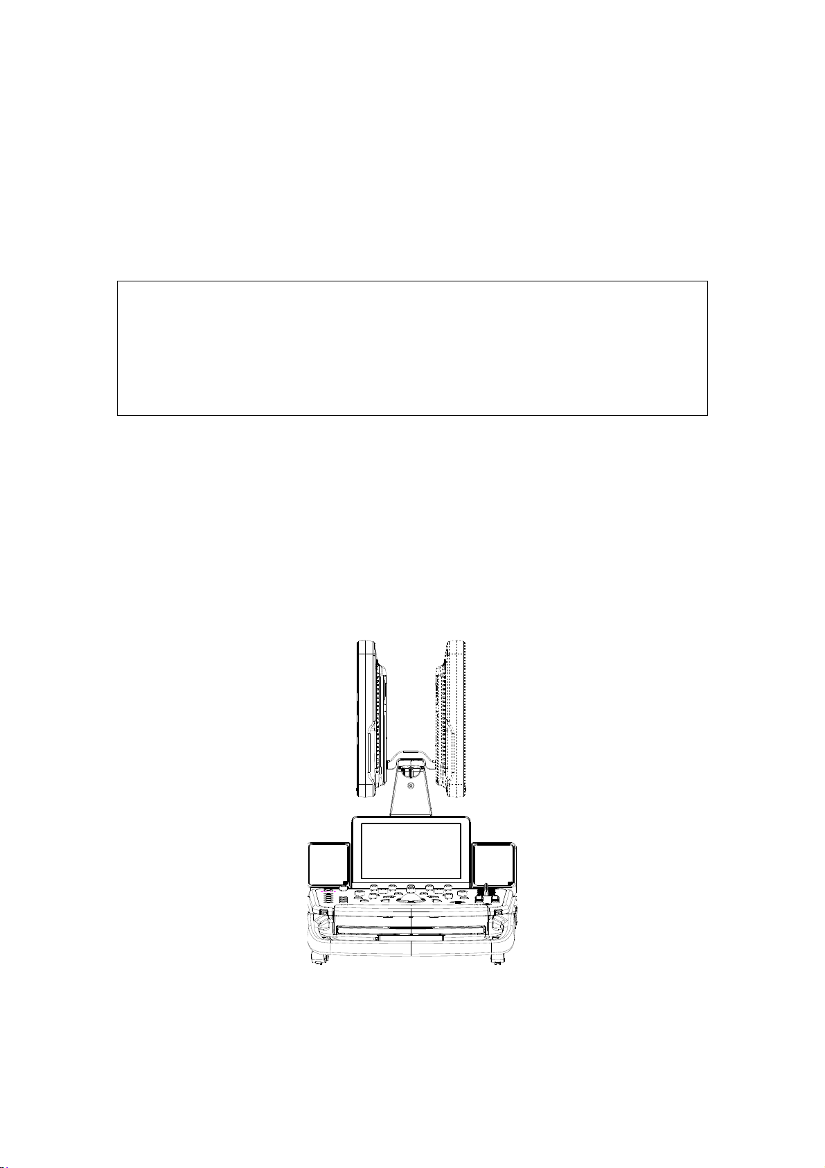
z Press the power button and select “Standby”.
z Disconnect the power plug, and select “Standby” in the prompted dialogue box.
When the system enters the standby status, the standby status indicator blinks in
orange.
To exit standby
z Press the power button.
When the system enters the standby status, if need to power off:
z Long press the power button for 5s.
z Press the power button to exit the standby status and then power off the system.
NOTE: 1. Power off the system if you will not use the system for a long period of time
(including storage/ transportation conditions), and you should not allow the
system in standby status, otherwise the batteries will be out of power and
permanently damaged.
2. If you will not use the system for a long period of time, DO NOT leave the
system in standby status, you should shut down the system, disconnect
mains power, and turn off powers of all connected peripherals.
3.4 Monitor Adjusting
3.4.1 Monitor Position Adjusting
Gently hold the bottom edge of the monitor when adjusting its position.
Rotate the monitor
z Monitor rotation
The monitor can be rotated ±90° .
3-6 System Preparation
Page 49
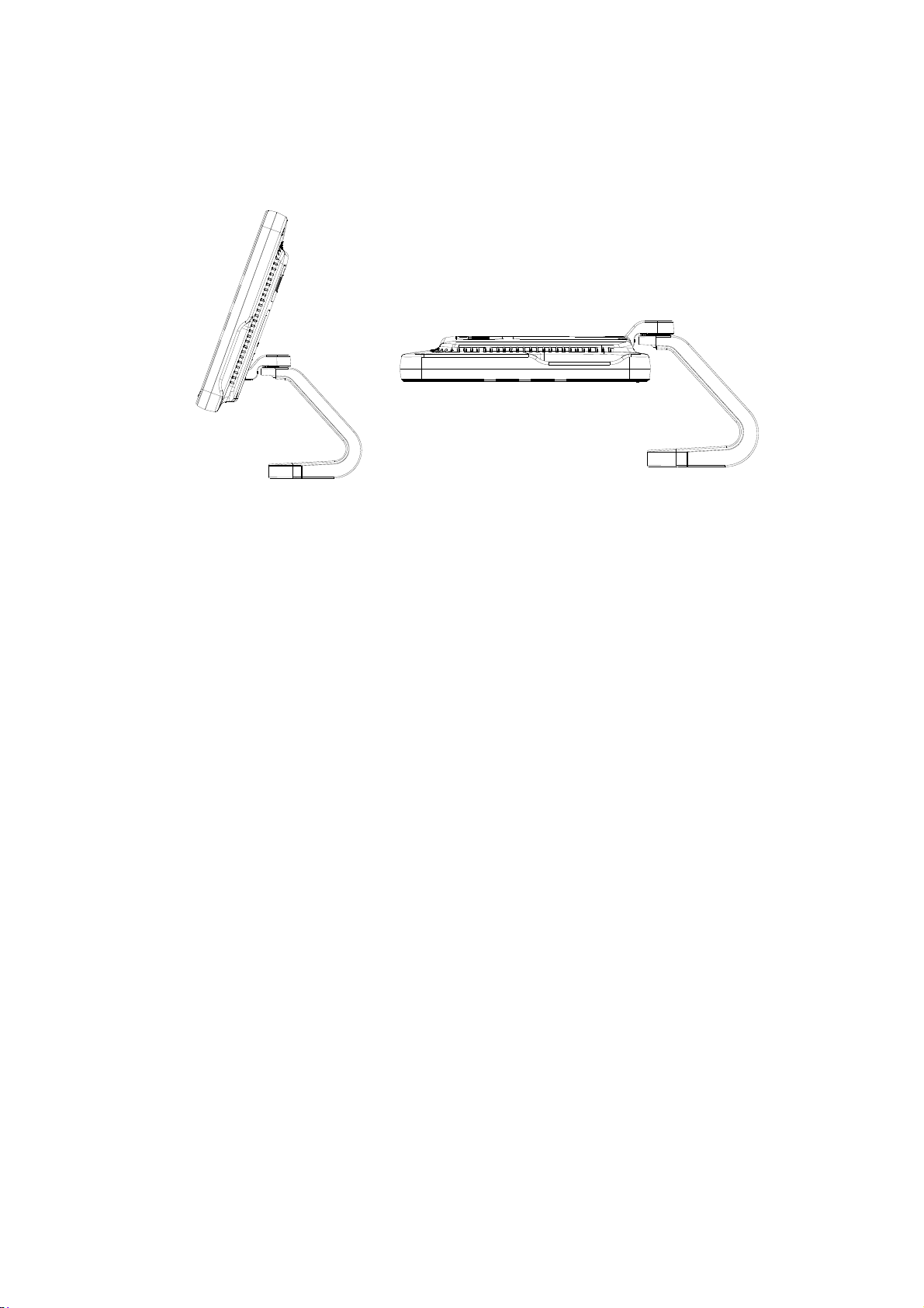
Tilt the monitor
When positioned vertically, the monitor can be tilted 20° backward and can be tilted
forward to a horizontal position. When transporting or moving the system, keep the
monitor in the horizontal position, as shown below:
3.4.2 Adjusting Brightness/Contrast on the Monitor
Monitoring the brightness and contrast adjustment is one of the most important factors for
proper image qualities. If set incorrectly, the gain, TGC, dynamic range or even acoustic
output have to be changed more often than necessary to compensate.
The adjusting buttons are shown as follows:
Brightness adjustment:
<1>, <2> refer to the brightness control keys with a sun marked at the top. Key <1>,
marked with a “-” on the top, can be used to decrease the brightness, while key <2>,
marked with a “+” on the top, can be used to increase the brightness.
Contrast adjustment:
<3>, <4> refer to the contrast control keys with a moon marked at the top. Key <3>,
marked with a “-” on the top, can be used to decrease the contrast, while key <4>,
marked with a “+” on the top, can be used to increase the contrast.
System Preparation 3-7
Page 50
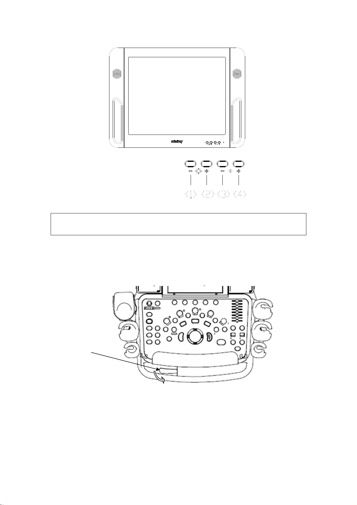
NOTE: On the monitor, the brightness adjustment comes before contrast. After
readjusting the monitor’s contrast and brightness, adjust all preset and
peripheral settings.
3.4.3 Control Panel Position Adjustment
Press the control lever downwards for about 30° to rotate the control panel ±90°. Press
the lever downwards for about 60° to move the control panel upwards or downwards.
Control
lever
3-8 System Preparation
Page 51
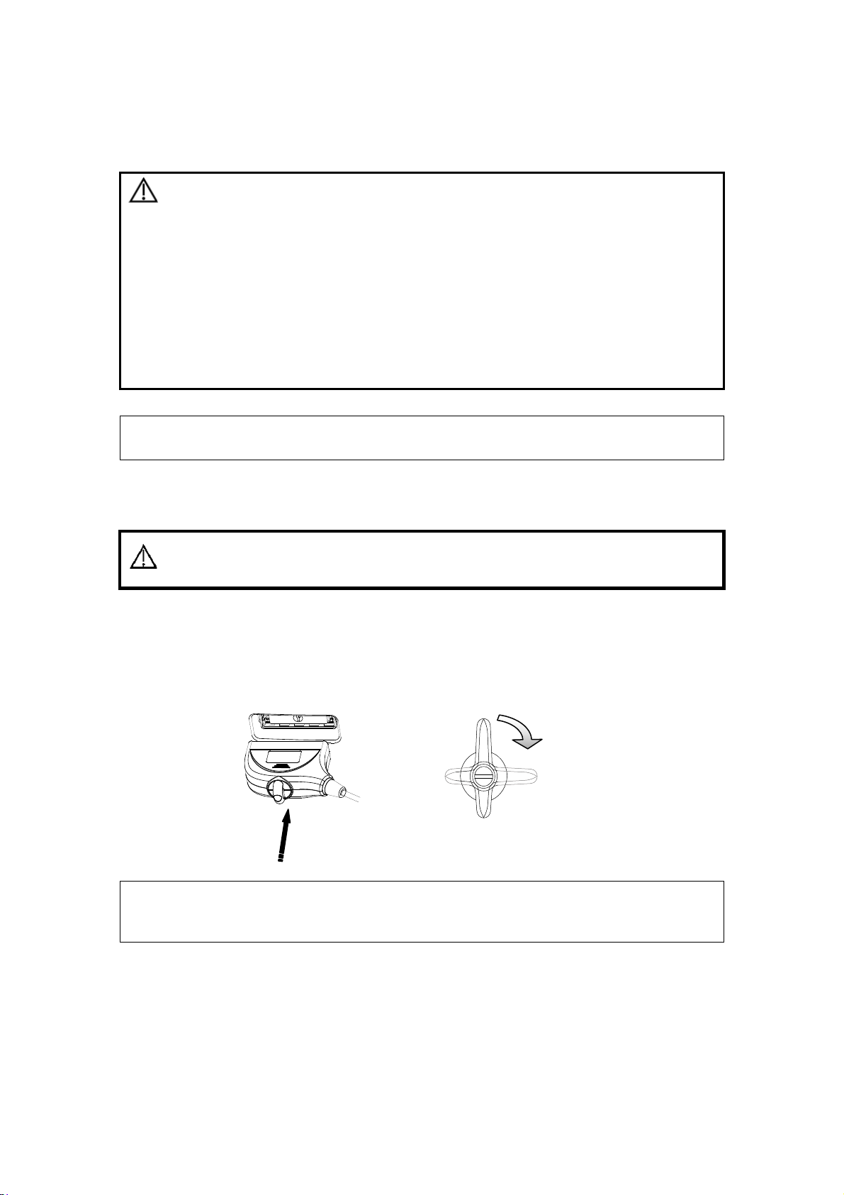
3.5 Connecting a Probe
CAUTION:
NOTE: If a probe port is not used for a long period of time, please use the dustproof
cover to protect the probe port from dust; otherwise bad contact may result.
1. Press <Freeze> to freeze an image or turn off the power of
the system before connecting/disconnecting the probe.
Otherwise, system or probe failure may occur.
2. When connecting or disconnecting a probe, place it in a
proper position, to prevent the probe from falling off or
becoming damaged.
3. Hang the probe cable to the hanger located under the
control panel to avoid excessively bending and damaging
the cable.
4. Only use the probes provided by Mindray. Aftermarket
probes may result in damage or cause a fire.
3.5.1 Connecting a Probe
The probes, cables and connectors should be in proper
WARNING:
1. Keep the cable end of the transducer to the right side of the system, insert the
connector into the system port, then press in fully. (Shown in the left figure)
2. Turn the lock handle 90° clockwise to lock it securely. (Shown in the right figure)
3. Position the probe properly to avoid it being treaded on or becoming wrapped around
other devices. DO NOT allow the probe head to hang free.
operating order and free from surface defects, cracks and
peeling. Otherwise, this may lead to electrical shock.
Lock
NOTE:
Before inserting the connector into the probe port, inspect the connector pin. If
the pin is bent, do not use the probe until it has been
inspected/repaired/replaced.
3.5.2 Disconnecting a probe
1. Turn the locking lever 90° counterclockwise to the vertical position. (Shown in the left
figure)
2. Pull the transducer connector straight out vertically (shown in the figure below).
System Preparation 3-9
Page 52
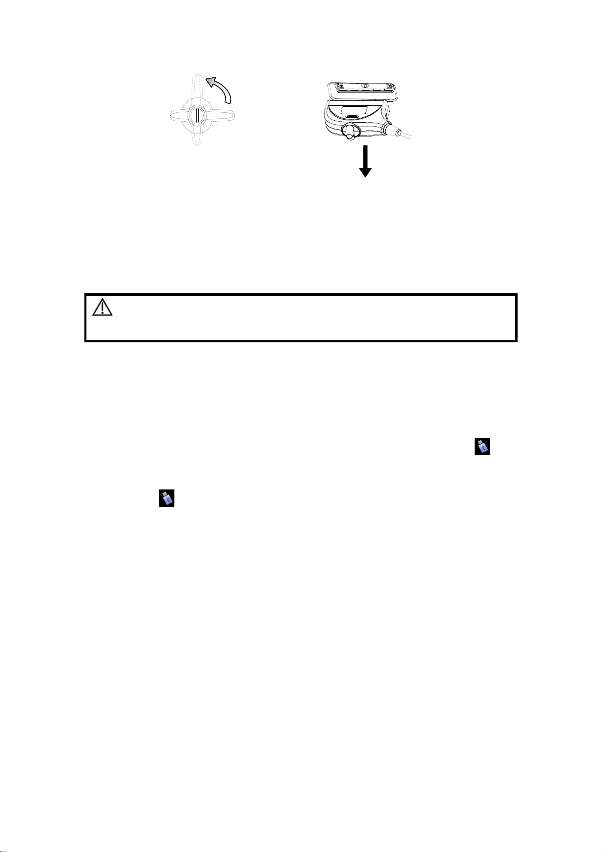
loose
3.6 Connecting Peripheral Devices
3.6.1 Connecting the USB Devices
WARNING:
Available USB ports on the system:
1. Two USB ports on the physiological-signal panel.
2. Two USB ports on the I/O panel at the back of the system.
3. Two USB ports on the control panel.
4. One USB port in the printer room, which is dedicated for digital video printer.
When connecting a USB memory device to the ultrasound system via a USB port,
you can hear a sound if it is connected successfully. You can see the symbol
the lower right corner of the imaging screen.
To remove the USB memory device:
(1) Click
(2) Select the memory device to be removed.
(3) Click [OK] and you can hear a sound. There will be sound feedback when
remove the USB memory device.
DO NOT directly remove a USB memory device;
otherwise, the USB memory device and/or the system
may be damaged.
to open the “Remove USB Device” dialogue box.
in
3.6.2 Connecting a Footswitch
Connection
Directly insert the USB port of the footswitch to the system applicable USB ports.
3-10 System Preparation
Page 53
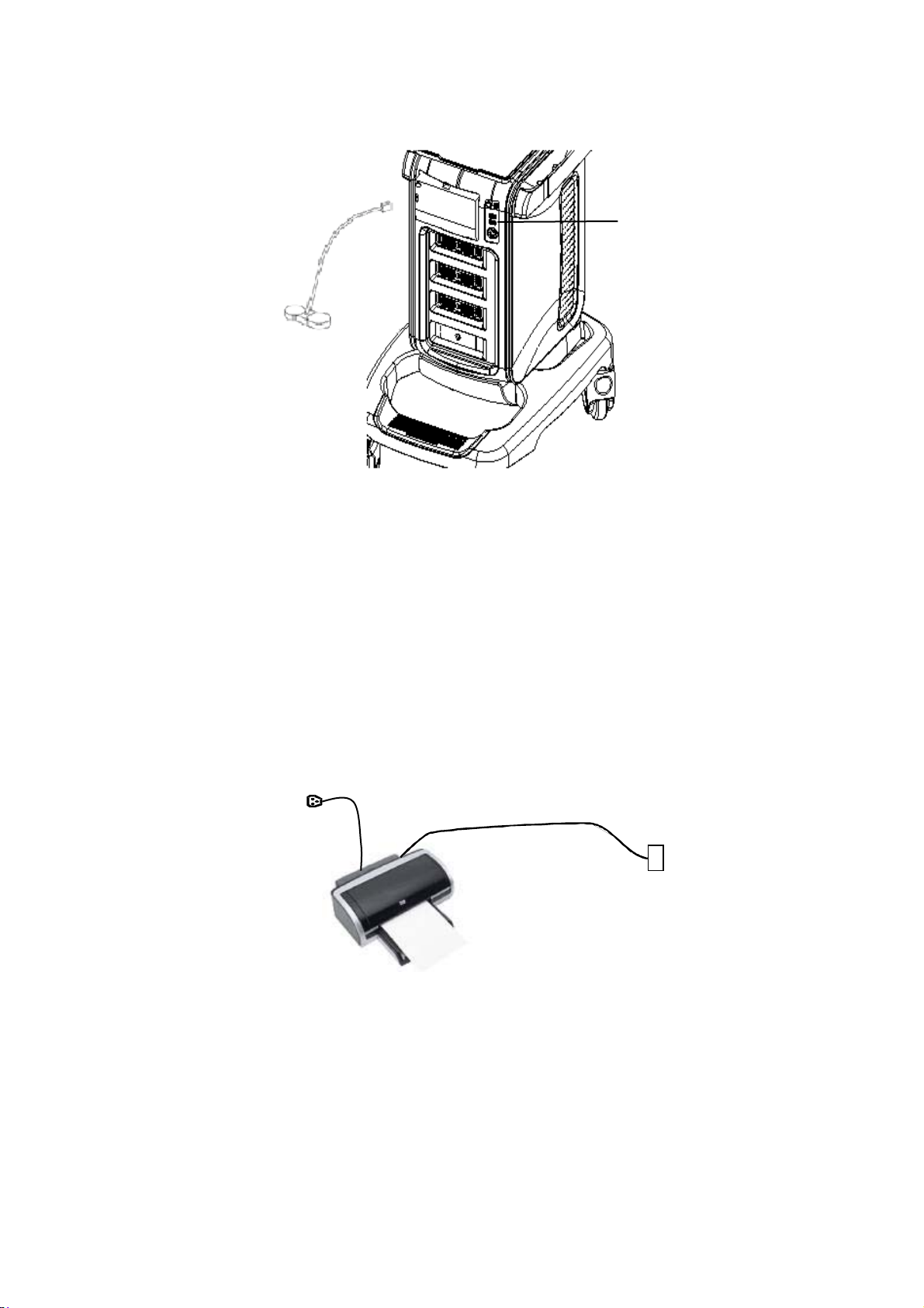
USB port
Function setting
The function of the footswitch can be set, for details, please refer to “12.1.6 Key
Configuration”.
3.6.3 Graph /Text printer
3.6.3.1 Connecting a Local Printer
As shown in the figure below, a graph / text printer has a power cord and data cable. The
power cord shall be directly connected to a wall receptacle as required.
Power cord
Data cord
USB port
1. Connect the data cable with the USB port on the ultrasound system.
2. Plug the other end power plug into an appropriate outlet.
3. Power on the system and the printer.
4. Check the printer status:
z Enter [Setup]Æ[Print Preset]Æ“Printer Driver” page, printers that are installed
automatically will be displayed in the list with the “Status” of “Ready”.
System Preparation 3-11
Page 54
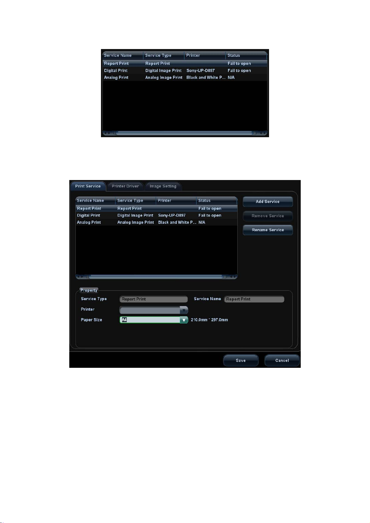
5. Return to “Print Service” page, and select “Report Print” in the list, and set attributes
in the Property box under the screen:
h Select the printer model from the drop-down list right to the “Printer”;
h Set Paper Size.
6. Click [Save] to finish the installation.
Tips: Drivers of some popular printers have already been integrated in the system, and
will be installed automatically. You need to check the following information to check if the
auto-installation fails:
z Model of the connected printer is not displayed in the “Printer Driver” list;
z Click “Printer Driver”Æ[Add Printer]Æ[Add Local Printer], the system will prompts
you to update the ppd file.
At this time, you need to install the printer driver manually as described in the
following:
3-12 System Preparation
Page 55

a) Download the ppd file from the printer manufacturer’s official website
(contact service engineer if necessary), and copy the ppd file to the storage
device (USB disk as an example).
b) Connect the USB disk to the ultrasound system, click [Setup]Æ[Print Preset]
”Printer Driver”Æ[Add Printer] to run the ppd file and finish the installation.
NOTE: All printer drivers integrated in the ultrasound system come from official website
of each printer manufacturer (you can check models in the [Setup]Æ[Print
Preset]Æ”Printer Driver”Æ[Printer Supported ]).Printer drivers may not be
updated in time due to software version and region limitation, consult printer
manufacturer for details.
3.6.3.2 Add Network Printer
1. Make sure the target network printer and the ultrasound system are both connected
into the same LAN.
2. Check the IP address of the network printer (for details, please refer to the
accompanying documents of the printer).
3. Enter [Setup]Æ[Print Preset]Æ”Printer Driver” page, click [Add Printer] to enter the
screen, type in the IP address of the network printer. (Port is 9100 in default).
4. Click [Verify Net Printer], the IP address, name and port information of the network
printer will be displayed under the “Port” box. Change the port to match the verified
printer information if necessary.
5. Click [OK] to enter the ppd installing screen:
z Select PPD file from media: select the path from the external media and install.
z Select PPD file from database: select the ppd. file integrated in the ultrasound
system.
6. After the ppd. file is installed completely, enter the printer name to finish the
installation.
7. After installation succeeds, the system returns to the “Printer Driver” page and
displays the added network printer.
3.6.3.3 Installing a Wireless Printer
The system supports wireless graph/text printer for report printing.
1. Plug the printer power cord into an appropriate outlet.
2. Power the system and the printer on.
3. Make sure the ultrasound machine and the printer are connected to the same LAN,
and turn the printer's W-LAN function on.
4. Add a wireless adapter, following the steps described in “Add network printer.”
5. Open the [Setup]Æ[Print Preset] page, select “Report Print” from the printer list,
select the printer to be the wireless printer, and set properties.
6. Click [Save] to exit the preset and make the settings effective.
3.6.3.4 iStorage UltraAssist Print
The system supports printing by iStorage function. Before using this function, please make
sure that the iStorage server has configured a defaulted printer, and the ultrasound
system has configured an iStorage server. For details, please refer to “12.5.2 iStorage”.
1. Enter [Setup]Æ[Print Preset]Æ”Printer Driver” and check iStorage printer status,
which should be AssistPrinter@IP address with “Ready” status.
System Preparation 3-13
Page 56

2. Click “Print Service” to enter the screen, and select AssistPrinter@IP address to be
the printer for the Report Print service.
3. Verify the status of the network connection.
Click the [Ping] button in the [Status] column of the iStorage printer list, and the system
pops a dialog box to display whether the connection with the iStorage server is ready
or not.
NOTE: Check if the iStorage printer is well connected with the server when the printing
fails with the verification result being Ready,
4. Click [Save] .
3.6.3.5 Print Service
You can use a graph/ text printer to print report or images.
z To set the default report printer and its attribute:
In "[Setup]Æ[Print Preset]" screen, select the "Print Service", select “Report
Print” column in the service list, set the items in the "Property" box.
z Report print:
Click [Print] in the report dialog box to print a report; or, use the user-defined key
to print, see "12.1.6 Key Configuration" for details.Please refer to the
accompanying manuals of the printers for more details.
3.6.4 Installing Analog Video Printer
1. Plug the printer power cord to an appropriate outlet.
2. Put the printer in a proper place.
3. Cable connection:
z B / W analog video printer
The printer compartment under the control panel provides the following cables:
(1) power cord;
(2) USB cable (used for connecting digital video printer);
(3) video signal cable;
(4) Remote control cable, as shown in the figure.
Connect the remote cable to the remote port of the printer, and video signal cable to
VIDEO IN port of the printer.
3-14 System Preparation
Page 57
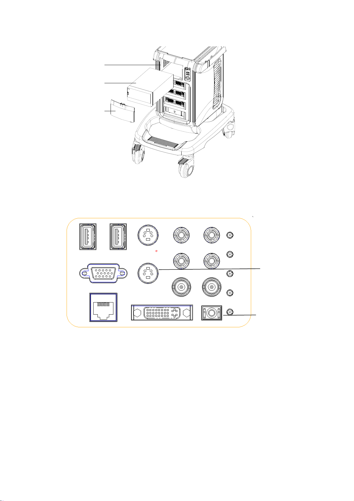
1
2
3
1. Printer room window 2. Printer 3. Room cover
z
Color analog video printer: use the I/O panel at the rear side of the machine to
connect the printer, as shown in the following figure:
Connect to
S-Video out
cable
Connect the
remote cable
of the printer
4. Load a paper roll, and turn on the system and printer.
5. Modify print service:
z Add a print service:
(1) Open the [Setup]Æ[Print Preset]Æ[Print Service].
(2) Click [Add Service] to enter the page.
(3) Select the service type and enter the service name manually.
(4) Click [OK] to return to the Printer Service page.
(5) Select the printer model, and then you can set the properties in the Property box.
(6) Click [OK] to complete the setting.
z Modify print service:
(1) Select an existed printer service in the list.
(2) Select the printer model, and then you can set the properties in the Property box.
(3) Click [OK] to complete the setting.
System Preparation 3-15
Page 58

3.6.5 Installing Digital Video Printer
1. Put the printer in a proper place.
2. Plug the printer power cord to an appropriate outlet.
3. Use a USB cable to connect between the USB port of the system and the USB port
of the printer.
4. Load a paper roll, and turn on the system and printer.
5. See section “3.6.3 Graph /Text printer” for driver installation procedure (drivers of
printers listed in the “2.5.4 Peripherals Supported” chapter are installed already).
z Add a print service:
(1) Open the [Setup]Æ[Print Preset]Æ[Print Service] screen.
(2) Click [Add Service] to enter the Print Service page.
(3) Select the service type and enter the service name manually.
(4) Click OK to return to the Printer Service page.
(5) Set printing properties.
(6) Click [OK] to complete the setting.
z Modify print service:
(1) Select an existed printer service in the list.
(2) Select the printer model, and then you can set the properties in the Property box.
(3) Click [OK] to complete the setting.
3.6.6 Installing a Wireless Printer
The system supports wireless graph/text printer for report printing.
1. Plug the printer power cord into an appropriate outlet.
2. Power the system and the printer on.
3. Make sure the ultrasound machine and the printer are connected to the same LAN,
and turn the printer's W-LAN function on.
4. Add a wireless adapter, following the steps described in “Add network printer.” See
chapter “3.6.3 Graph /Text printer” for details.
5. Open the [Setup]Æ[Print] page, select “Report Print” from the printer list, select the
printer to be the wireless printer, and set properties.
6. Click [Save] to exit the preset and make the settings effective.
3.6.7 Installing/ uninstalling Probe/Gel Holder
Installing
As shown in the figure below, align the buckle of the holder to the slot at the side of the
control panel and then insert the buckle into the slot until the buckle clicks and locks.
3-16 System Preparation
Page 59

Uninstalling
Press the clip in the direction of the arrow to get out the holder.
Clip
System Preparation 3-17
Page 60

3.7 Basic Screen and Operation
3.7.1 Basic Screen
The following diagram maps out the different areas in the screen:
Menu/exam
mode/image
parameter
Logo
Hospital name
Operator ID
Probe&acoustic power
DOB/
age
Image area
Patient
name
Gender
Accession# Freeze icon
Exam
date&time
Thumbnails
Image-inimage
Thumbnail
Soft menu Tips Soft menu
Help Information System Icon
Information Area
The information area displays manufacturer logo, hospital name, exam date & time,
operator, probe, acoustic power & MI/TIS, freeze icon, patient information, ECG icon
(if ECG module is configured), and accession #, etc.
To preset the patient banner display content: open the [Setup]Æ[System
Preset]Æ[General] screen, and check the content in the “Patient Info” box in the
upper left corner of the screen.
z Logo
Manufacture logo, displayed in the upper left corner of the screen.
3-18 System Preparation
ECG trace
Image
manage
Cine Review
Page 61

z Hospital name
Display the hospital name. Hospital name can be set via "[Setup]Æ[System
Preset]Æ[Region]".
z Exam time
Displays the exam time, including date and time. Exam time format can be set
via "[Setup]Æ[System Preset]Æ[Region]". Exam time will be frozen with the
frozen image.
z Probe model
Displays the currently-used probe model, or the default model.
z Acoustic power & MI/TIS
Displays the acoustic power, including the acoustic power, MI (Mechanical Index)
and TIS.
z Freeze icon
The freeze icon
z Patient Information
means the image is frozen.
Displays patient name, ID, gender and age etc. Enter the patient information
through the "Patient Info" screen. Or, import the registered patient data from
iStation or the DICOM Worklist server.
z Operator
Displays the operator’s name on the screen. This information is entered through
the “Patient Info” screen.
z ECG icon
Displays ECG icon, which consists of a heart icon and heart rate, e.g.
75bpm"
"
z Accession#
Serial number used in DICOM or the manually entered serial number in “Patient
Info” screen.
Image Parameter and Menu Area
The image parameter and menu are both displayed in this area. When no menu is
available; this area displays the image parameters of the current imaging mode.
Current exam mode is also displayed here.
z Menu area
When an image menu is displayed, the imaging parameters will be covered by
the menu.
Include image menu, measurement menu, comment menu, body mark menu
and so on. Use the trackball to operate on the menu.
Use the <Menu> to show or hide the menu.
The menu area consists of menu title, menu items, etc. As shown in figure below.
System Preparation 3-19
Page 62

Menu title
Items
Drop-down list
button
h Menu title
Displays the menu name.
h Items
Refers to the items on a menu. For item that is applicable for more than one
mode, the item appears as shared item in the certain mode. Items of image
modes and measurement can be preset.
h Down-drop list button
If there are several options available for one item, you can choose the options
through the
h Return to previous menu
button.
Click [Return] to return to the previous menu.
Parameter Area
Displays the image parameters for the activated image window. If there are more
than one imaging modes, the system displays the parameters of each image
mode respectively. For details, please refer to the corresponding imaging
mode(s).
Image area
The image area displays the ultrasound images, ECG waveforms, probe mark (or
activating window mark), time line (in M or PW mode), coordinate axis (including
depth, time, velocity/frequency), focal position (located at depth axis in the form of
), besides, the annotation, body mark, measurement calipers, color bar/grayscale
bar are also displayed here.
Image-in-Image thumbnail area
In the zoom status, this area displays the thumbnail of a complete image, and a
rectangular frame is used to highlight the currently magnified area. This feature is
called image-in-image.
Cursor area
The status icon area indicates the current cursor status, such as
status.
Help information area
The help information area displays various help information or progress bar in the
current status.
Thumbnail area of images stored
Displays the thumbnail images stored under the current patient.
3-20 System Preparation
in cineloop
Page 63

Image manage area
z Page up/down: when there are more than one page images have been stored,
you can turn to the next or preview page by
z Delete: select a thumbnail image, and click to delete it.
z Send to: select a thumbnail image, and click to send it to external devices.
or respectively.
Soft Menu area
The monitor's soft menu area displays the items that simultaneously appear at the
bottom of the touch screen.
System status area
This area displays the relevant system icons, such as USB memory device, printer,
network connection, and current system time, etc.
None-fixing Area
Areas illustrated here are position-changeable; you can move them by the trackball
within a certain area on the monitor.
z Result window
The measurement result window displays the results of recently performed
measurements.
To move the result window:
a) Place the cursor on the title of result window (you can see the cursor
changes into
).
b) Press <Set> and move the trackball, the window moves together with the
cursor.
c) Move the cursor to the target position, press <Set> again to anchor the
result window in the target position.
z Comment area
For details, please refer to “9 Comments and Body Marks”.
z Body mark area
For details, please refer to “9 Comments and Body Marks”.
System Preparation 3-21
Page 64
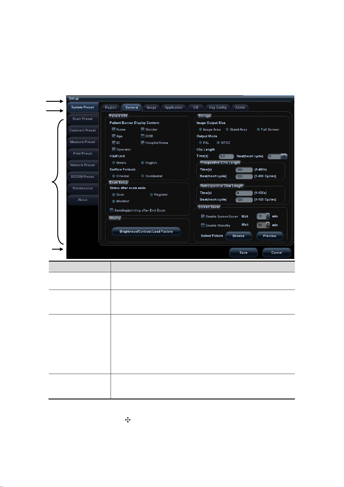
Title
Tab
Content
Control
button
3.7.2 Basic Operations of Screens
A screen consists of title, page tabs, contents and buttons, as shown in the following
figure:
Composition Description
Title Bar
Page Tab
Contents
[Save] and [Cancel]
To reposition a dialogue box:
1. Roll the trackball to move the cursor onto the title bar of the dialogue box. At this time
the cursor becomes a
2. Roll the trackball and reposition the rectangular graphic to the new desired location.
3. Press the <Set>, and the dialogue box is moved to the desired position.
The title bar is used to give a description for the content and
function of the screen.
For some screens, contents are distributed across several pages.
Click the tab by pressing <Set> key to open/close the available
pages.
Radio button: click to select the item.
Check box: click to check or uncheck the item.
Entry box: enter characters manually via the keyboard.
Position the cursor into the box, and then enter the letters or
characters.
Drop-down list box: click “▼” to show the list and select an
item.
When the operation of a screen is complete, press the [Save] or
[Cancel] button to save or cancel the operation, and close the
screen.
; press <Set>.
3-22 System Preparation
Page 65
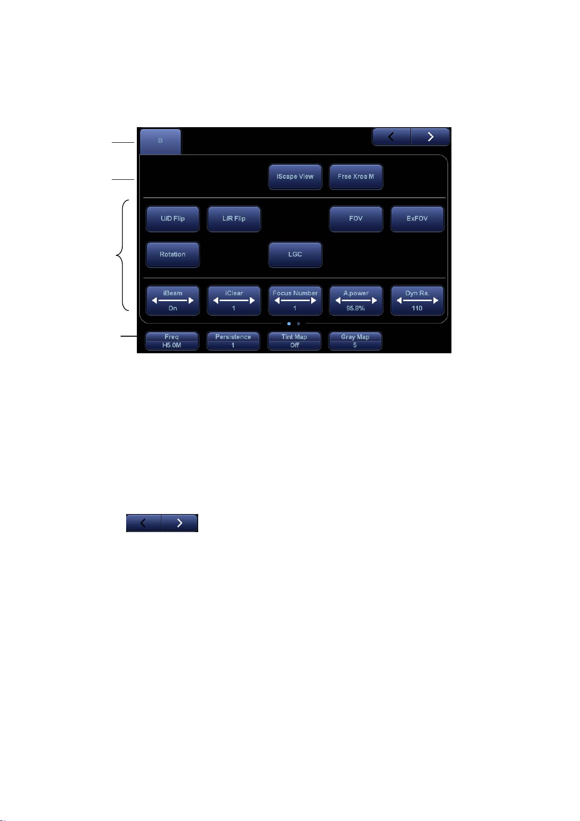
3.7.3 Touchscreen
Adjust through the touch screen
1
2
3
4
1. Mode displaying area (or main functional tabs): displays the current modes, touch
the tab to enter the mode.
2. Other application mode entrance: displays the available application modes related;
tap to enter the modes.
3. Parameter adjusting area: displays the parameters in the current imaging mode or
function.
z Parameter magnitude setting: tap ► or ◄ to increase/ decrease the value.
z ON/OFF setting: some of the parameters only can be set at ON or OFF, ON is to
activate the function, and when the function is activated, the key is highlighted in
green.
z Page selection: if there is more than 1 page for the current mode, tap
to turn the pages.
z Functional item: tap to go to the corresponding function.
4. Knob-adjusting area: displays the knob-controlled parameters.
There are five knobs at the bottom of the touch screen; their functions vary with the
current menu. Press or rotate the knobs to adjust the corresponding parameters.
Control Panel
Adjust through trackball, control panel key, deflector rod, knob or slider.
Trackball function keys
In some certain mode, you need to use both the trackball and the trackball function
keys to adjust.
For instance, in Color mode, use the trackball and the trackball function keys to
adjust ROI size/position.
System Preparation 3-23
Page 66
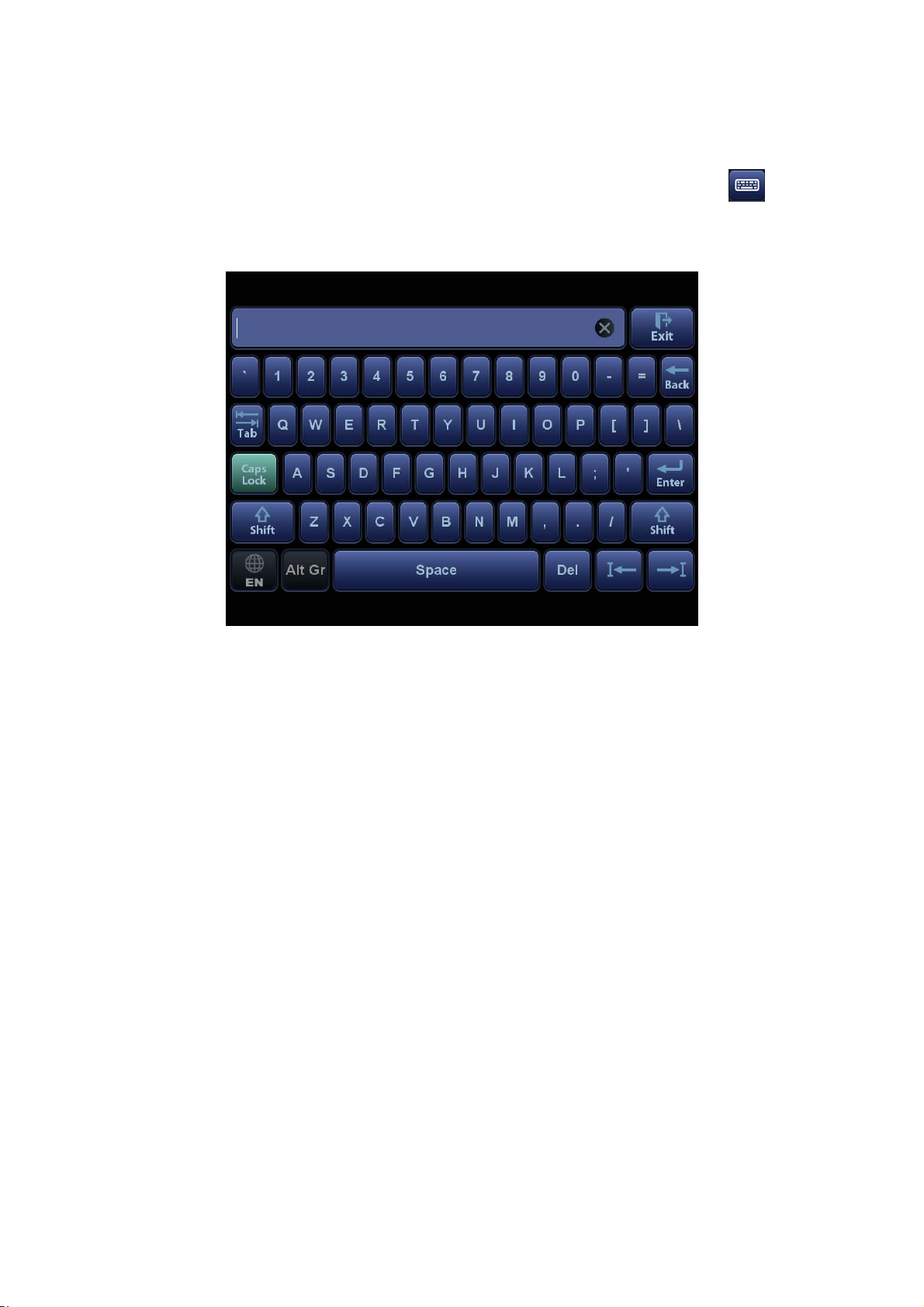
3.7.4 Soft keyboard
Under report, setup, comment adding and iStation screen, the soft keyboard icon is
displayed on the touch screen. Tap the icon to enter the soft keyboard typing screen.
Or, under patient info screen, you can see the soft keyboard typing screen on the touch
screen directly.
3-24 System Preparation
Page 67

4 Exam Preparation
CAUTION:
Before examining a new patient, press <End Exam> to end
the exam of the previous patient, update the patient ID and
information, to avoid mixing data of the next new patient.
4.1 To Start an Exam
You can start a patient exam in the following situations:
z New patient information: enter the patient information, if it is a new patient, refer
to "4.2.1 New Patient Information" for details.
z New exam: to start a new exam for an already registered patient, the recorded
information can be obtained either through iStation or Worklist, refer to "4.2.2.1
iStation" and "4.2.2.2 DICOM Worklist" for details.
z Activate an exam: select an exam that is ended within 24 hours, and continue
the exam. For details, please refer to “4.5.1 Activate an Exam ”.
General procedure for an exam: Enter the patient informationÆSelect an exam mode
and probeÆChoose an imaging modeÆStart the exam.
To start a new patient exam, it is better to enter the detailed patient information. The
system will set up a unique information database for each patient based on the patient
information entered, so that the information of one patient will not be confused with that
of another patient.
4.2 Patient Information
To enter the "Patient Info" screen
z Press <Patient>, or,
z Move the cursor onto the patient information area on the monitor and press
<Set> to open the screen.
To exit the "Patient Info" screen
z Click [OK] on the "Patient Info" screen; or, press <Patient> on the control panel
again, to save the settings and exit the screen.
z Click [Cancel] or press <Esc> to exit the screen without saving any of the
entered patient data.
z Press <B> or <Freeze> to return to the current exam mode with the entered
information being saved.
Click [Quick Register] on the screen to save the patient information quickly and
return to the main screen.
4.2.1 New Patient Information
The "Patient Info" screen is shown as follows (Take OB exam for example):
Exam Preparation 4-1
Page 68
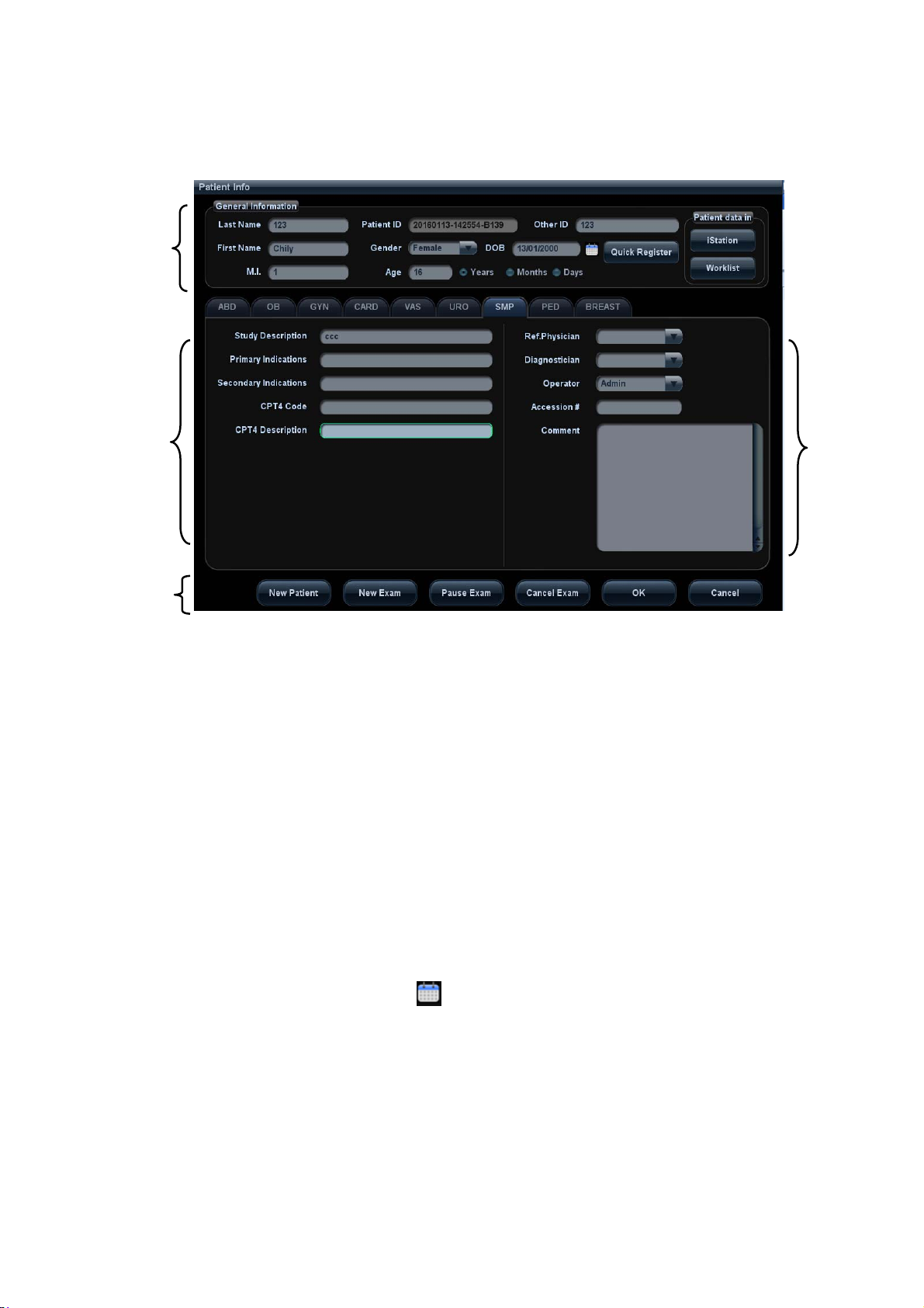
Place the cursor onto the targeted box. The field box is highlighted and a flashing cursor
appears. Information can be entered or selected from the options.
You can also change the cursor position by <Tab>, <Enter> or direction keys.
1
2
4
Detailed information is described as follows:
1. General information
z Patient ID
Patient ID is generated automatically by the system after starting a new patient,
and can be modified manually. Once you enter the ID and confirm it, you are not
allowed to change it.“\” is not permitted.
The ID can be obtained by the bar code reader as well.
For details, please refer to “Appendix A Barcode Reader”
z Name
Enter the patient name directly through the keyboard. Characters of A through Z
and 0 through 9 and “.” are allowed.
“\”, “^”, “=” and “,” are not permitted.
z Gender
Select Male, Female or Unknown for patient gender in the drop down list.
z DOB (Date of birth):
You can either enter the birth date of a patient manually according to the format
3
displayed in the field, or click to select the date. In the table, you can select
the desired year (or enter it manually); month and day, then click [OK] to finish it.
4-2 Exam Preparation
Page 69
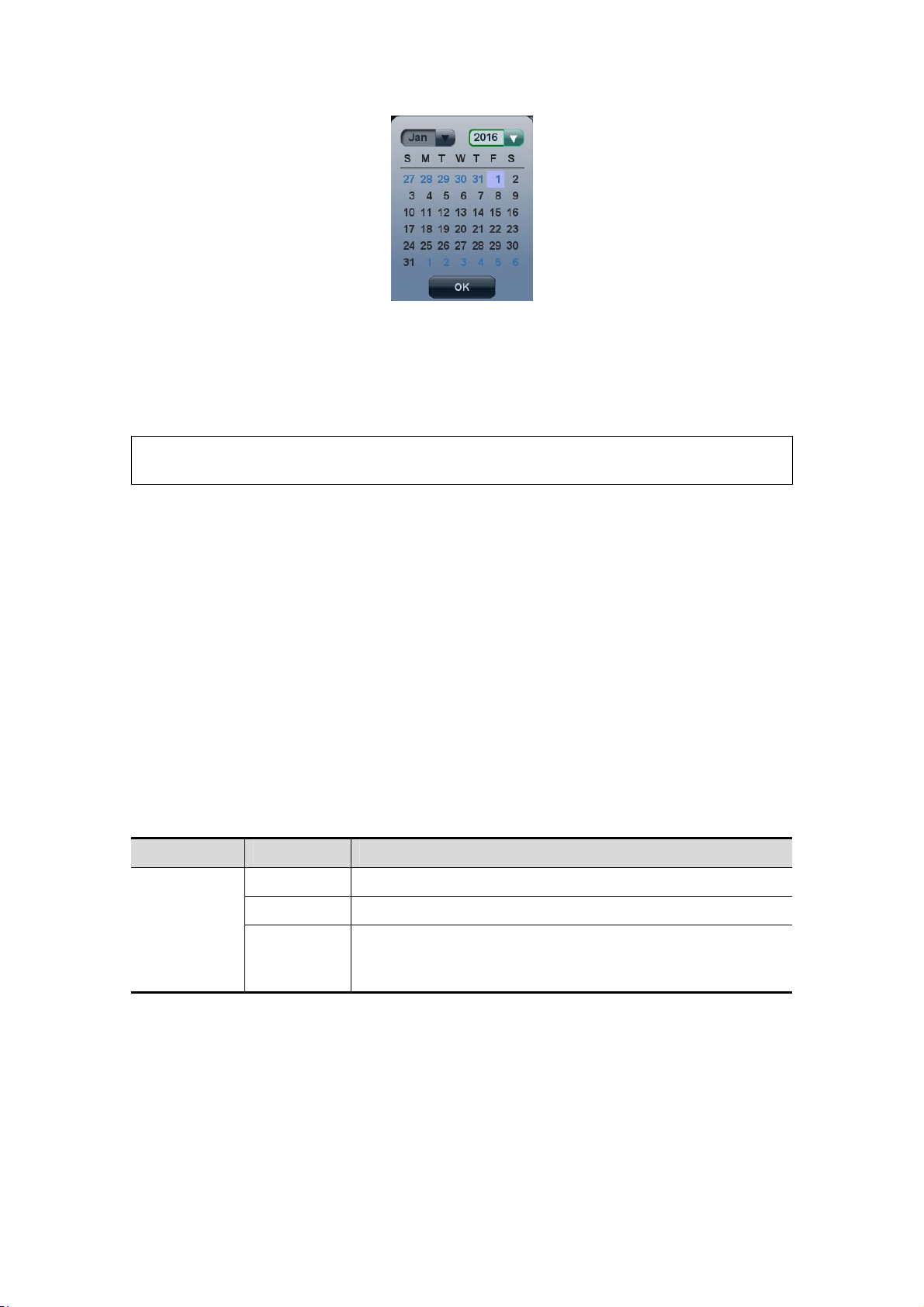
z
Age:
h Auto generated age: once the DOB is entered, the system can display an
auto-generated age in the field box; the unit can be “Years”, “Months” or
“Days”. If the age is less than one year, the system will automatically
calculate the age in months or days.
h Also, you can manually enter the age.
NOTE: When you enter the date manually, please enter it in the format as that of the
system.
2. Exam Type
z Exam application type
You can select among 9 types: ABD (Abdomen), OB (Obstetrics), GYN
(Gynecology), CARD (Cardiac), VAS (Vascular), URO (Urology), SMP (Small
Part), PED (Pediatrics), and Breast.
Select the exam type tab to enter the exam-specific information.
z General information:
Study description: To enter description for each exam.
Primary indications: To enter the primary indications (reason to perform the exam.)
Secondary indications: To enter the secondary indications.
CPT4 code: To enter the CPT4 code.
CPT4 description: To enter the CPT4 description.
Comment Exam specific explanation or remarks.
z Exam specified information:
Exam Type Information Description
Height /
ABD
(Abdomen)
Weight /
BSA (body
surface
area)
After the height and weight are entered, the system will
automatically calculate the BSA based on the formula
which is set via "[Setup] → [System Preset] → [General]".
Exam Preparation 4-3
Page 70

Exam Type Information Description
According to the entered index (can be selected in the
drop-down list); including LMP (last menstrual period),
date of conception (DOC), IVF (in vitro fertilization), PRV
(previous exam date), BBT (basic body temperature)), the
system can automatically calculate GA and EDD
(estimated delivery date); or, calculates GA and LMP
according to the EDD and entered date.
z LMP: After you enter LMP, the system will
calculate and display GA and EDD.
Calculation
index
z DOC: after you enter the DOC, the system will
calculate the GA and EDD.
z IVF: After you enter IVF, the system will calculate
GA and EDD.
OB
(Obstetric)
z PRV: input the date and GA of the last exam, the
system will calculate a new GA and EDD.
z BBT: input BBT, the system will calculate the GA
and EDD.
z EDD: after you enter EDD, the system will
calculate and display GA and LMP.
Gravida Times of pregnancy.
GYN
(Gynecology)
Cardiology
Ectopic
Times of abnormal pregnancy. e.g. extrauterine
pregnancy.
Gestations Number of embryos (1, 2, 3;4, 1 is default).
Para Times of delivery.
Aborta Times of abortion.
LMP Last menstrual period.
Gravida Times of pregnancy.
Para Times of delivery.
Ectopic
Times of abnormal pregnancy. e.g. extrauterine
pregnancy.
Aborta Times of abortion.
IVF Info
Female hormone basic level and drugs inducing the
ovulation.
Height /
Weight /
BSA (body
surface
area)
After the height and weight are inputted, the system will
automatically calculate the BSA based on the formula
which is set via "[Setup] → [System Preset] →[General]".
BP Blood pressure.
HR /
RA Press Right Atrium Pressure.
VAS
(Vascular)
Height /
Weight /
4-4 Exam Preparation
Page 71

Exam Type Information Description
BP(L) Input left blood pressure.
BP(R) Input right blood pressure.
URO
(Urology)
SMP (Small
Parts)
PED
(Pediatrics)
Breast
3. Operating Information
z Accession #: exam number used in DICOM. It should be entered within 16
letters or characters; “\” is not permitted.
z Diagnostician: people who is responsible for the exam. "\", "^","=" and "," are
not permitted.
z Operator: people who is responsible for images acquisition and scanning. "\", "^",
"=" and "," are not permitted.
z Ref. Physician: the people who requires the ultrasound exam. "\", "^", "=" and ","
are not permitted.
4. Functional key
z [Pause Exam]: to pause the current exam.
z [Cancel Exam]: to cancel the current exam.
z [New Patient]: click to clear the current patient information in the patient
information screen in order to input information of a new patient.
z [New Exam]: click to clear the entered exam information to start a new exam for
the current patient.
z [OK]: click to save the patient data entered and exit the screen.
z [Cancel]: click to cancel the patient data entered and exit the screen.
Serum PSA /
PPSA
coefficient
None /
None /
Height /
Weight /
/
4.2.2 Retrieve Patient Information
4.2.2.1 iStation
The patient data can be obtained in iStation from the system hardware or USB memory
device. You can enter the searching conditions for the patient.
1. To enter iStation screen (the screen is shown as follows):
z Press <iStation> on the control panel; or,
z Click [iStation] in the "Patient Info" screen; or,
z Press the <Review> key on the control panel and click [iStation] in the screen.
Exam Preparation 4-5
Page 72
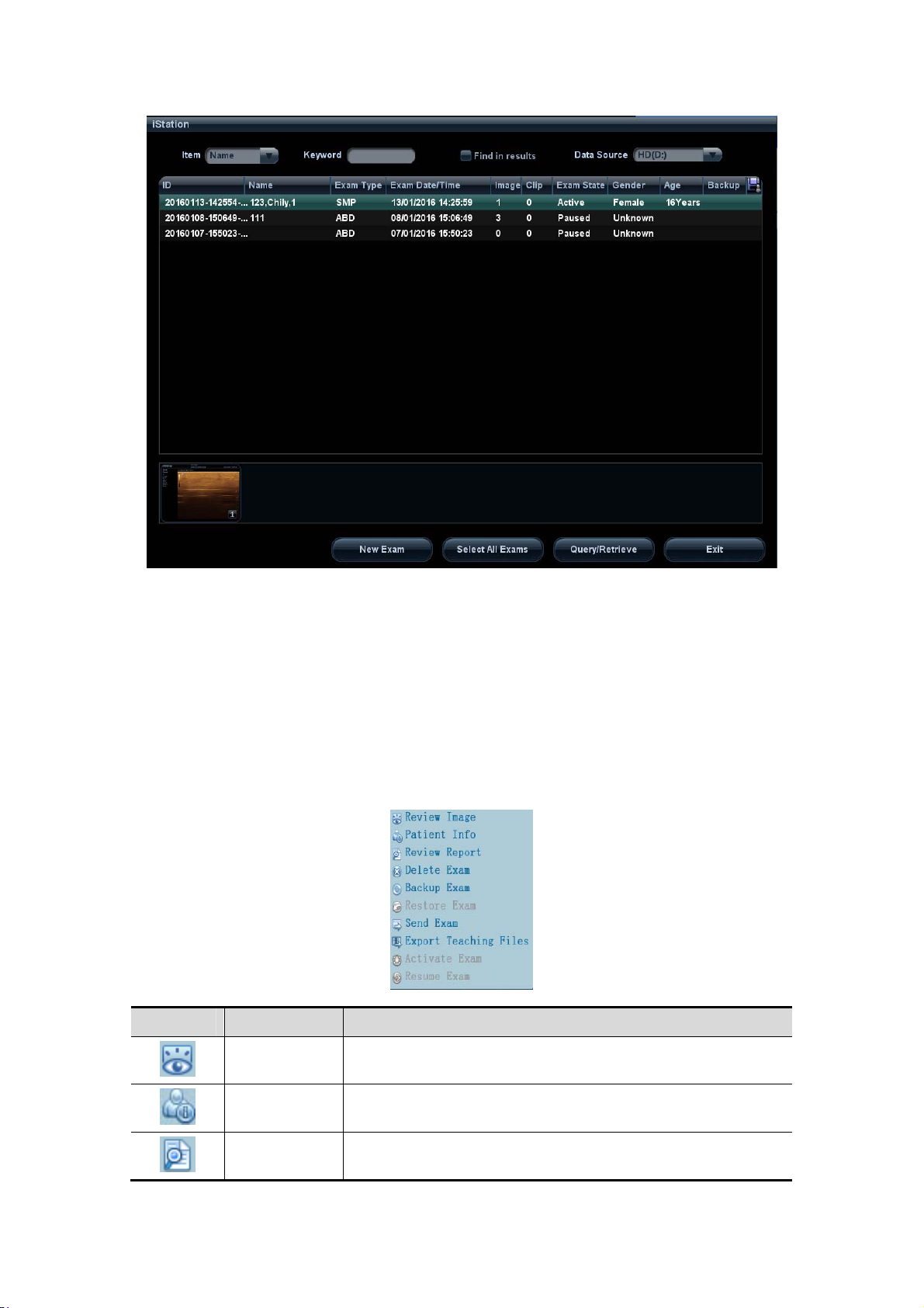
2. Select the data source:
Select the data source in the drop-down list of "Data Source". The occupying space
percentage of the selected data source will be displayed.
3. Set the searching condition
Define the searching item: Name, ID, BOD or Exam Date; and then enter the related
keyword.
z Select “Find in results”, the system will search the keyword based on the existed
searched results.
4. Select the desired patient information in the list, and the system pops up the
following menu:
Button Function Description
Review an
Image
Patient
Information
Review
Report
Click to enter the Review screen.
Click to enter the Patient Info screen.
Click to enter diagnostic report screen.
4-6 Exam Preparation
Page 73
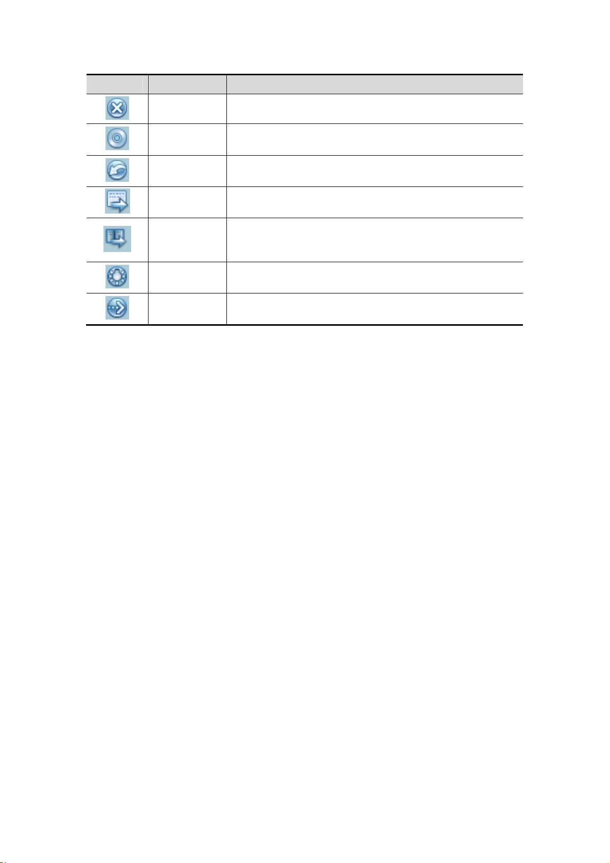
Button Function Description
Delete Exam Click to delete the selected record.
Backup Exam
Click to back up the selected patient record to media
supported.
Restore
Exam
Send Exam
Export
Teaching
Files
Activate
exam
Continue
Exam
Click to import the patient data from an external media.
Click to send the selected patient data to external device,
DICOM storage server or printer.
Click to send the selected record to external devices as
teaching file.
Click to continue an exam that has been finished within 24
hours.
Click to continue an exam that has been paused within 24
hours.
Other buttons:
z [New Exam]: click to enter Patient Info screen, meanwhile, the corresponding
patient information is also imported to the new exam. After you edit the patient
information in the Patient Info screen, select [OK] to start a new exam.
z [Select All Exams]: click to select all records.
z [Exit]: click to exit iStation.
4.2.2.2 DICOM Worklist
When the DICOM basic package is configured and the Worklist server has been set, click
[Worklist] in the "Patient Info" screen to query or import the patient data. (For details
about Worklist server setting, please refer to the DICOM chapter.)
Procedure:
1. Select data source: choose a worklist server in the drop-down list of “Worklist Server”,
and then all the patient exam records in the server are listed out.
2. Set the searching condition:
z Enter the period which includes the exam date, and click [Query] to search.
z Enter patient ID, patient name, accession #, the system provides the result in
real-time.
z Or select the keyword type, enter the keywords and then click [Query] to search.
z To reset the criteria, click [Clear] button.
3. Select the desired patient from the list, and:
z Click [Start Exam], the patient information is imported into the system and then
an exam is started.
z Click [Transfer], the patient information is imported into the "Patient Info" screen.
After you edit the patient information in the "Patient Info" screen, click [OK] to
start a new exam.
z Click [Show Detail] to see details of patient data.
4. Click [Exit] to exit the Worklist.
Exam Preparation 4-7
Page 74

4.3 Select Exam Mode and Probe
CAUTION:
Selecting exam mode
1. Connect suitable probes to the system and press <Probe> on the control panel. The
touch screen displays the following dialog box:
If the exam mode is changed during a measurement, all
measurement calipers on the image will be cleared. The general
measurement data will be lost, but application measurement data
will be stored in the reports.
2. Tap the screen to select the probe type and exam mode. The system exits the dialog
box and enters the selected exam mode and probe.
Click [Exit] or press <Probe> again to cancel the selection and exit the screen.
4.3.1 Dual-probe Switch
A user-defined key for dual-probe switch can be defined in preset, by which you can fast
switch the probe under B/ Color/ Power mode.
This function applies only to probes with the same exam modes.
1. Scan to obtain the image by current probe.
2. Press the user-defined key. The available probes appear on the screen.
3. Choose the probes to be compared. The system enters dual-probe mode. The image
from previous probe is frozen.
4. Scan and obtain the required image from the current probe.
5. Press the user-defined key to switch the images of two probes.
The path for setting the keys: <F10 Setup>Æ[System Preset]Æ[Key Config].
1. Select the key to be defined from [Key] tab on the left side. Or, select a key from
[Footswitch] tab.
4-8 Exam Preparation
Page 75

2. Select [Image Mode]Æ[Dual Probe].
3. Click [OK] to confirm the setting or exit. The setting comes into effect then.
4.4 Select the Imaging Mode
Use the corresponding keys in the control panel to enter the imaging modes.
4.5 Activate& Continue an Exam
4.5.1 Activate an Exam
In iStation screen, select the exam record finished within 24 hours, and click [Activate
Exam] from the menu popped up; or, click [Active Exam] in iStation or Review screen to
activate the exam.
Tips:
z The system can automatically load the patient information and exam data to
continue the exam.
z If you want to continue an exam with data in an external memory database, you
have to first allow the system to load the patient data to the system’s patient
database.
4.5.2 Continue Exam
In iStation screen, select an exam record paused within 24 hours, click [Resume Exam]
from the menu popped up to continue the exam.
If you want to select a patient data in an external memory database, you have to first
allow the system to load the patient data to the system’s patient database.
4.6 Pause & End an Exam
4.6.1 Pause Exam
Sometimes, you have to stop an uncompleted exam due to some special reasons.
When the exam is paused, the system can begin other exams.
(1) Press <Patient> to enter Patient Info screen.
(2) Click [Pause Exam].
If the system is powered off during scanning, the exam status turns "paused" after
the system restart.
Only one exam can be paused every time.
When an exam is paused, the system will:
(1) Save the exam-related images, reports and measurement data, modifies the
status as “Paused”.
(2) Save the exam information, including imaging mode, exam mode, image
parameters, operation mode and so on.
Exam Preparation 4-9
Page 76

4.6.2 End Exam
Before examining a new patient, press <End Exam> to end the exam of the previous
patient, update the patient ID and information, to avoid mixing data of the next new
patient.
To end an exam, you can do one of the following:
z Press <End Exam> on the control panel.
z Click [New Patient] on the Patient Info screen to end the last patient exam and
clear the patient information.
z Click [New Exam] on the Patient Info screen (or iStation screen, or Review
screen) to end the last exam and clear the exam data.
4-10 Exam Preparation
Page 77

5 Image Optimization
WARNING:
The images displayed in this system are for
reference only. Mindray is not responsible for
the correctness of diagnostic results.
In Dual-B imaging mode, the measurement
results of the merged image may be
inaccurate. Therefore, the results are provided
for reference only, not for confirming
diagnoses.
5.1 Imaging Mode
5.1.1 Switching Between Imaging Modes
Switch between imaging modes according to the actual situation.
5.1.2 Image Adjustment
Adjust using the touch screen.
1
2
3
4
1. Mode display area (or main functional tabs): displays the current modes. Tap the tab
to enter the mode.
Image Optimization 5-1
Page 78

2. Other application mode access: displays the available related application modes. Tap
to enter the modes.
3. Parameter adjusting area: displays the parameters in the current imaging mode or
function.
z Parameter magnitude setting: tap or to increase/decrease the value.
z ON/OFF setting: some of the parameters can only be set to ON or OFF. ON
activates the function, and when the function is activated the key is highlighted in
green.
z Page selection: if there is more than 1 page for the current mode, tap
to turn the pages.
z Functional item: tap to go to the corresponding function.
4. Knob-adjusting area: displays the knob-controlled parameters.
There are five knobs at the bottom of the touch screen. Their functions vary
depending on the current menu. Press or rotate the knobs to adjust the
corresponding parameters.
5.1.3 Quickly Saving Image Settings
Press <F7> or user-defined key for QSave to access the image data saving dialog box.
Save the image parameter adjustment:
Click [Save] to save the current image values for the current exam mode of the
particular probe.
Create new exam data (using the current image parameter settings):
Enter the name in the box after “Save As” to assign a name for a user-defined exam
mode, and click [Create] to save the current image parameters, measurements,
comments and body mark settings to the exam mode.
Restore the factory settings:
The settings of the current exam mode and the probe can be restored to factory data
by clicking [Restore].
5-2 Image Optimization
Page 79

Check image parameter level and other settings:
z Click [Show Parameter] to check levels of different image parameters. Click [OK]
to save the current image values for the current exam mode of the particular
probe.
This function is not available under dual-probe frozen mode.
5.2 B Mode Image Optimization
B mode is the basic imaging mode that displays real-time images of anatomical tissues
and organs.
5.2.1 Basic Procedures for B Mode Imaging
1. Enter the patient information. Select an appropriate probe and exam mode.
2. Press <B> on the control panel to enter B mode.
3. Adjust the parameters to optimize the image.
4. Perform other operations (e.g., measurement and calculation) if necessary.
Press <B> on the control panel to return to B mode at any time.
5.2.2 B Mode Parameters
In B mode scanning, the image parameter area in the top-right corner of the screen
displays the real-time parameter values as follows:
Parameter F D G FR DR iClear iBeam iTouch Zoom
Meaning Frequency Depth Gain
Frame
Rate
Dynamic
Range
Display when the function is turned
on.
Image Optimization 5-3
Page 80

5.2.3 B Mode Image Optimization
Frequency
Description This function is used to select the operating frequency of the current
probe, the real-time value of which is displayed in the image parameter
area in the upper left corner of the screen, where “F” represents B mode
frequency.
Operation You can select a harmonic frequency or a B mode frequency.
Adjust the frequency value through the [Freq] item in the soft menu, “H”
indicates harmonic frequency. Values of frequency vary depending upon
the probe types.
Select the frequency according to the detection depth and current tissue
characteristics.
Effects The higher the frequency the better the near field resolution but the worse
the force of penetration.
Harmonic imaging enhances near field resolution and reduces lowfrequency and large amplitude noise, so as to improve small parts
imaging.
Gain
Description To adjust the gain of the whole receiving information in B mode. The real-
time gain value is displayed in the image parameter area on the top-right
corner of the screen.
Operations Rotate the <B> knob clockwise to increase the gain, and counter-
clockwise to decrease it.
The adjusting range is 0-100 in increments of 1.
Effects Increasing the gain will brighten the image and you will see more received
signals. However, noise may also be increased.
Depth
Description This function is used to adjust the sampling depth, the real-time value of
which is displayed in the image parameter area on the top-right corner of
the screen.
Operations Use the <Depth> deflector rod in the bottom-right part of the control panel
to adjust the depth.
The adjustable depth values vary depending on the probe types.
Effects Increase the depth to see tissue in deeper locations, or decrease the
depth to see tissue in shallower locations.
5-4 Image Optimization
Page 81

TGC
Description The system compensates the signals from deeper tissue by segments to
optimize the image.
There are 8-segment TGC sliders on the control panel corresponding to
the areas of the image.
Operations To increase the gain compensation in an area of interest, move the TGC
slider to the right.
To decrease the gain compensation in the corresponding area of interest,
move the TGC slider to the left.
About 1.5 seconds after the adjustment is complete, the TGC curve
disappears.
Effects Adjust the signal gain for a particular image area to achieve a balanced
image.
Acoustic Power
Description Refers to the power of ultrasonic waves transmitted by the probe, the real-
time value of which is displayed in the upper part of the screen.
Operations Adjust the acoustic power through the [A.Power] item on the touch screen.
The adjusting range is 3.2-100%.
Effects Generally, increasing the acoustic power will increase the brightness and
contrast of the image and the force of penetration.
Impacts You should perform exams according to actual situations and follow the
ALARA Principle.
Focus
Description
Operations Adjust the focus number using the [Focus Number] item on the touch
Effects The area that is focused will be of a higher contrast and resolution.
Impacts The greater the number of focal zones, the slower the frame rate.
Refers to adjusting the focus of the ultrasonic beams, using the “
symbols which are displayed to the right of the image.
screen.
Use the <Focus> deflector rod in the bottom-right part of the control panel
to adjust the focus position.
In B mode, the available focus number can be switched between 1-4.
”
Image Optimization 5-5
Page 82

Imaging Adjustment
Description More information can be obtained without moving the probe or changing
the sampling position.
FOV (Field
of View)
B Steer Use the <Angle/Steer> key on the control panel to adjust the steer angle.
ExFOV
(Extended
FOV)
Impacts The FOV position/range is available only for convex and phase probes.
1. To change the scan range, tap [FOV] on the touch screen to enter the
FOV range and FOV position adjustment status.
2. Press <Set> to switch between FOV range and FOV position.
3. Rotate the trackball to adjust the FOV position or the FOV range.
When the scan range is adjusted to its widest, the FOV position cannot be
changed.
You can get a much larger field of view when selecting a larger FOV.
The frame rate decreases when using a larger FOV.
Tap [ExFOV] on the touch screen to turn the function on/off.
For linear probes, the ExFOV function displays as trapezoid imaging.
For convex probes, the ExFOV function displays as extending the
scanning angle.
The ExFOV function is available only for linear and convex probes.
The B Steer function is available only for linear probes.
Line Density
Description The function determines the quality and information of the image.
Operations Adjust the line density using the [Line Density] item on the touch screen.
There are four levels of line density available: UH, M, H, L.
Effects The higher the line density, the higher the resolution.
Impacts The higher the line density, the lower the frame rate.
Dynamic Range
Description This function is used to adjust the B image resolution to compress or
expand the gray display range. The real-time value displays in the image
parameter area in the top-right corner of the screen.
Operations Adjust the dynamic range through the [Dyn Ra.] item on the touch screen.
Rotate the knob clockwise to increase the value. Rotate the knob
counterclockwise to decrease the value.
The adjusting range is 30-240dB, in increments of 5dB.
Impacts The more the dynamic range, the more specific the information and the
lower the contrast with more noise.
5-6 Image Optimization
Page 83

iClear
Description The function is used to enhance the image profile so as to distinguish the
image boundary for optimization.
Operations Adjust using the [iClear] item on the touch screen.
The system provides 1-4 levels of iClear adjustment: off represents no
iClear effect, and the bigger the value the stronger the effect.
Impacts It may cause increased noise.
Persistence
Description This function is used to superimpose and average adjacent B images, so
as to optimize the image and remove noise.
Operations Rotate the knob under the [Persistence] item on the touch screen to adjust
the value.
The system provides 7 levels of frame average adjustment: the bigger the
value the stronger the effect.
Effects Persistence can remove image noise to make details clearer.
Impacts Increasing Persistence may lead to missing signals.
Rotation/Invert (U/D Flip and L/R Flip)
Description The function provides better observation for image display.
Rotation Rotate the image using the [Rotation] item on the touch screen.
Images can be rotated by 0°, 90°, 180° and 270°.
When the image is rotated by 90° or 270°, the depth scale is displayed in
the top part of the screen.
Invert (U/D
Flip and
L/R Flip)
Effects You can identify the image orientation using the “M” mark on the screen.
To invert the image horizontally or vertically.
Tap [U/D Flip] or [L/R Flip] on the touch screen to invert the image
By default, the M mark is located in the top-left corner of the imaging area.
iBeam (Spatial Compound Imaging)
Description This function is used to superimpose and average images of different
steer angles to achieve image optimization.
Operations Adjust using the [iBeam] item on the touch screen.
The system provides difefnt levels of iBeam adjustment in single B mode.
Off represents no iBeam.
Effects Images can be optimized with less spot noise and higher resolution, so
that more details for the structure are revealed.
Impacts iBeam is valid for linear and convex probes, and it is not available when
the ExFOV function is turned on.
Image Optimization 5-7
Page 84

Image Merge
Description In the Dual-split mode, when the images of the two windows have the
same probe type, depth, invert status, rotation status and magnification
factor, the system will merge the two images so as to extend the field of
vision.
Operations Turn the function on or off using the [Auto Merge] item on the touch
screen.
Impacts The function is valid only for linear probes.
Gray Map
Description This function applies the gray correction to obtain optimum images.
Operations Select from among the maps by rotating the knob under the [Gray Map]
item on the touch screen. The system provides 25 different gray effect
maps.
Tint Map
Description This function provides an imaging process based on color difference
rather than gray distinction.
Operations Rotate the knob under the [Tint Map] item on the touch screen to select
the map. The system provides 25 different color effect maps.
TSI (Tissue Specific Imaging)
Description The TSI function is used to optimize the image by selecting acoustic
speed according to tissue characteristics.
Operations Select from among the TSI modes using the [TSI] item on the touch
screen.
The system provides four ways of optimizing for specific tissues: general,
muscle, fluid and fat.
iTouch (Auto Image Optimization)
Description To optimize image parameters as per the current tissue characteristics for
a better image effect.
Operations Press <iTouch> on the control panel to turn the function on.
The iTouch symbol will be displayed in the image parameter area in the
top-right corner of the screen once <iTouch> is pressed.
Select different levels of iTouch effect using [iTouch] on the touch screen.
Long press the <iTouch> key to exit the function.
5-8 Image Optimization
Page 85

H Scale
Description Display or hide the width scale (horizontal scale).
The scale of the horizontal scale is the same as that of the vertical scale
(depth). They change together in zoom mode, or when the number of the
image window changes. When the image is turned up/down, the H Scale
will also be inverted.
Operations Tap [H Scale] on the touch screen to display or hide the scale.
LGC
Description Adjust the gain of scan lines to increase the image lateral resolution.
Operation Tap [LGC] on the touch screen to access the adjusting dialog box.
The 8 rods displayed on the touch screen indicate the corresponding
image areas on the main screen.
Tap the
or move upwards to increase the gain.
The system also provides several preset parameters for imaging.
to adjust the gain, move downwards to decrease the gain,
Image Optimization 5-9
Page 86

5.3 M Mode Image Optimization
5.3.1 Basic Procedures for M Mode Imaging
1. Select a high-quality image during B mode scanning, and adjust to position the area
of interest in the center of the B mode image.
2. Press <M> on the control panel, and roll the trackball to adjust the sampling line.
3. Press <M> on the control panel again or <Update> to enter M mode. You can then
observe the tissue motion along with the anatomical images of B mode. During the
scanning process, you can also adjust the sampling line accordingly when necessary.
4. Adjust the image parameters to obtain optimized images.
5. Perform other operations (e.g., measurement and calculation) if necessary.
If “Sampling Line Displaying” is selected, then the screen will display the sampling line all
the time and pressing <M> one will lead to entering M mode directly. See “5.1.3 Quickly
Saving Image Settings” chapter for details.
5.3.2 M Mode Image Parameters
In M mode scanning, the image parameter area in the top-right corner of the screen
displays the real-time parameter values as follows:
Parameter F D G V DR
Meaning Frequency Depth M Gain M Speed M Dynamic Range
During M mode imaging, menus for B mode and M mode are displayed on the touch
screen at the same time. You can switch between the 2 modes by clicking the mode
tabs.
During M mode scanning, the frequency, depth, focus position and acoustic power of
the probe are synchronous with that of B mode.
Adjustment of the depth, focus position or TGC to the B mode image will lead to
synchronous changes in the M mode image.
5-10 Image Optimization
Page 87

5.3.3 M Mode Image Optimization
Gain
Description To adjust the gain of M mode image. The real-time gain value is displayed
in the image parameter area in the top-right corner of the screen.
Operations Rotate the <M> knob clockwise to increase the gain, and counter-
clockwise to decrease it.
The adjusting range is 0-100 in increments of 1.
Effects Increasing the gain will brighten the image and you will see more received
signals. However, noise may also be increased.
Display Format
Description To set the display format of M mode images and B mode images.
Operations Tap the different display format ratio buttons on the touch screen to adjust.
There are 5 formats available for image display: H2:3, V2:3, V3:2, V3:1,
Full.
Effects Select different format types according to the actual situation and obtain a
desired analysis through comparison.
Speed
Description This function is used to set the scanning speed of M mode imaging, and
the real-time speed value is displayed in the image parameter area in the
top-right corner of the screen.
Operations Rotate the knob under the [Speed] item on the touch screen to adjust.
There are 1-6 levels of scan speed available: the smaller the value the
faster the speed.
Effects Changing speed makes it easier to identify disorders in cardiac cycles.
Tint Map
Description This function provides an imaging process based on color difference
rather than gray distinction.
Operations Rotate the knob under the [Tint Map] item on the touch screen to select
the map. The system provides 1-25 different color effect maps. Off
represents the function is disabled.
Press the knob under the [Tint Map] item on the touch screen to turn the
function on/off.
Gray Map
Description This function applies the gray correction to obtain optimum images.
Image Optimization 5-11
Page 88

Operations To select from among the maps, turn the knob under [Gray Map] item on
the touch screen. The system provides 25 different gray effect maps.
Edge Enhance
Description This function is used to enhance the image profile so as to distinguish the
image boundary for optimization.
Operations Adjust using the [Edge Enhance] item on the touch screen.
There are 0-3 levels of edge enhance adjustment available: the bigger the
value the stronger the effect.
Impacts Larger edge enhance may lead to increased noise.
Dynamic Range
Description This function is used to adjust the M image resolution to compress or
expand the gray display range.
The real-time dynamic range value is displayed in the image parameter
area in the top-right corner of the screen.
Operations Rotate the knob under the [Dyn Ra.] item on the touch screen.
The adjusting range is 30-240dB, in increments of 5dB.
Effects The more the dynamic range, the more specified the information.
M Soften
Description This feature is used to process the scan lines of M images to reject noise,
making image details clearer.
Operations Adjust using the [M Soften] item on the touch screen.
The system provides 0-14 levels of M Soften adjustment: the bigger the
value the stronger the effect.
5-12 Image Optimization
Page 89

5.4 Color Mode Image Optimization
The Color mode is used to detect color flow information, and the color is designed to
judge the direction and speed of blood flow.
Generally, the color above the color bar indicates the flow towards the probe, while the
color below the color bar indicates the flow away from the probe. The brighter the color,
the faster the flow speed, while the darker the color, the slower the flow speed.
5.4.1 Basic Procedures for Color Mode Imaging
1. Select a high-quality image during B mode scanning, and adjust to position the area
of interest in the center of the B mode image.
2. Press <Color> to enter B + Color mode. Roll the trackball to change the position and
size of the Region of Interest (ROI) and press the <Set> key to set.
3. Adjust the image parameters during scanning to obtain optimized images.
4. Perform other operations (e.g., measurement and calculation) if necessary.
5.4.2 Color Mode Image Parameters
In Color mode scanning, the image parameter area in the top-right corner of the
screen displays the real-time parameter values as follows:
Parameter F G PRF WF
Meaning Frequency Color Gain Pulse Repetition Frequency (PRF) Color Wall Filter
During Color mode imaging, the image optimizing menus for B mode and Color
mode are displayed on the touch screen at the same time. You can switch between
the 2 modes by clicking the mode tabs.
In Color mode, the acoustic power is synchronous with that of B mode. Adjustment of
the depth to the B mode image will lead to corresponding changes in Color mode
image.
5.4.3 Color Mode Image Optimization
Color Gain
Description Refers to the overall sensitivity to flow signals. This function is used to
adjust the gain in Color mode. The real-time gain value is displayed in the
image parameter area in the top-right corner of the screen.
Operations Rotate the <Color> knob clockwise to increase the gain, and counter-
clockwise to decrease it.
The adjusting range is 0-100 in increments of 2.
Effects Increasing the gain will increase the flow signal presented and noise. The
signals may be missing when the gain is adjusted too low.
Image Optimization 5-13
Page 90

ROI Adjustment
Description This function adjusts the width and position of the ROI in Color mode.
Operations When the ROI box is a dotted line, roll the trackball to change the size.
When the ROI box is a solid line, roll the trackball to change the position.
Press <Set> to switch between the solid line and the dotted line.
Impacts The larger the ROI box, the lower the frame rate, and the lower the
resolution and color sensitivity.
B/C Align
Description To set and restrict the maximum width of the B mode image to that of the
Color ROI.
Operations Turn the function on or off using the [B/C Align] item on the touch screen.
Impacts The frame rate increases when the function is turned on.
Dual Live
Description This function is used to display the B image and Color image
synchronously.
Operations Turn the function on or off using the [Dual Live] item on the touch screen.
When the function is turned on, the window will automatically switch to
dual windows (one for the B image, and the other for the Color image).
Steer
Description The feature is used to adjust the ROI of the color flow of different angles
with immobility of the linear probe.
Operations Adjust using the <Angle/Steer> key on the control panel.
Effects This function is used to adjust the scan angle of linear probes, so as to
change the angle between the transmitting beam and flow direction.
Impacts Steer is only valid for linear probes.
Line Density
Description Line density determines the quality and information of the image.
Operations Adjust using the [Line Density] item on the touch screen.
4 levels of line density are provided: H, L, UH, M.
Effects The higher the line density, the higher the resolution.
Impacts The higher the line density, the lower the frame rate.
5-14 Image Optimization
Page 91

Packet Size
Description This function is an indication of the ability to detect flow, which is used to
adjust the accuracy of color flow.
Operations Rotate the knob under the [Packet Size] item on the touch screen to adjust
the value.
There are 0-3 levels of packet size available: 0 represents no packet size
control and the bigger the value the higher the sensitivity.
Effects The higher the packet size, the more sensitive the indication for low-
velocity flow.
Impacts Adjusting the packet size may lead to the frame rate changing.
Persistence
Description This function adjusts the temporal smoothing in Color mode to optimize
the image.
Operations Adjust through the [Persistence] item on the touch screen.
The system provides 0-4 levels of persistence adjustment: 0 represents no
persistence, and the bigger the value the stronger the effect.
Smooth
Description This feature is used to reject noise and smooth the image.
Operations Adjust using the [Smooth] item on the touch screen.
The system provides 0-4 levels of smooth function: the bigger the value
the stronger the effect.
Image Optimization 5-15
Page 92

Scale
Description This function is used to adjust the speed range of the color flow, which is
adjusted using the PRF in the system. The real-time PRF value is
displayed in the image parameter area in the top-right corner of the
screen.
Operations Adjust through the [Scale] item on the touch screen.
The adjusting range varies according to the frequency, probe and depth.
Adjust according to the actual situation.
Effects Provides a much clearer color flow image.
Use a low PRF to observe low-velocity flows, and a high PRF to observe
high-velocity flows.
Impacts Aliasing may occur if a low-velocity scale is used and high velocities are
encountered.
Low velocities may not be identified when a high-velocity scale is used.
Baseline
Description Refers to the area where the velocity is zero in the scale. Adjust according
to the actual situation so as to get an optimum flow display.
Operations Adjust through the [Baseline] item on the touch screen.
A positive value means increase the signals above the baseline, and a
negative value means increase the signals below the baseline.
Invert
Description To set the display mode of the color flow. The color scale will be inverted
when the function is turned on.
Operations Turn the function on or off using the [Invert] item on the touch screen.
Select “Auto Invert” in “[Setup] (F10)Æ[System]Æ[Image]”, so the color
bar can automatically invert when the color flow is steered to a certain
angle to accommodate the operator’s desire to distinguish the flow
direction.
Auto invert function is available only for linear probes.
Map
Description This function is a combination of several image parameters, which
indicates the display effect of the color image.
Operations Rotate the knob under the [Map] item on the touch screen to select from
among the maps.
The system provides 21 different maps for selection. The V group provides
11ordinary maps and the VV group provides 10 2D maps.
5-16 Image Optimization
Page 93

WF (Wall Filter)
Description It filters out low-velocity signals to provide effective information, and this
function is used to adjust the filtered frequency. The real-time value is
displayed in the image parameter area in the top-right corner of the
screen.
Operations Select using the [WF] item on the touch screen.
There are 0-7 levels of wall filter function available. Select the value
according to the actual situation.
Impacts Flow signals may be missing.
Priority
Description This function is used to set the levels of the flow display and to display the
grayscale signal or color signal.
Operations Rotate the knob under the [Priority] item on the touch screen to select the
value.
The adjusting range of the priority is 0-100% in increments of 10%.
The higher the value, color signals are first to be displayed. The lower the
value, grayscale signals are first to be displayed.
Velocity tag
Description This function is used to mark the specified velocity range in the flow to
check the flow function or specific flow velocity value.
Operation 1. Tap [Velocity Tag] on the touch screen to enter the velocity marking
status. A green mark appears on the color bar.
2. Roll the trackball upwards and downwards to select the marking
velocity.
3. Press <Set> to enter the tag range selection status, and roll the
trackball upwards and downwards to select the range.
Press <Set> to switch between marking position and marking range.
iTouch (Auto Image Optimization)
Description To optimize image parameters as per the current tissue characteristics for
a better image effect.
Operations Press <iTouch> on the control panel to turn the function on.
Image Optimization 5-17
Page 94

5.5 Power Mode Image Optimization
Power mode provides a non-directional display of the blood flow in terms of intensity as
opposed to flow velocity.
DirPower (Directional Power mode) provides additional information of the flow direction
toward or away from the probe.
5.5.1 Basic Procedures for Power Mode Imaging
1. Select a high-quality image during B mode or B + Color scanning, and adjust to
position the area of interest in the center of the image.
2. Press <Power> to enter B + Power mode. Roll the trackball to change the position of
the Region of Interest (ROI) and press the <Set> key to set. Roll the trackball to
change the size and position of the ROI.
3. Adjust the image parameters during B + Power mode scanning to obtain optimized
images.
4. Perform other operations (e.g., measurement and calculation) if necessary.
5.5.2 Power Mode Image Parameters
In Power mode scanning, the image parameter area in the top-right corner of the
screen displays the real-time parameter values as follows:
Parameter F G PRF WF
Meaning Frequency Power Gain Pulse Repetition
Frequency (PRF)
During Power mode imaging, the image optimizing menus for B mode and Power
mode are displayed on the touch screen at the same time. You can switch between
the 2 modes by clicking the mode tabs.
In Power mode, the acoustic power is synchronous with that of B mode. Adjustment
of the depth to the B mode image will lead to corresponding changes in Power mode
image.
Parameters consistent with those in Color mode and B mode are not to be introduced.
See the relevant Color mode and B mode sections, while special items of the Power
mode are introduced in the following.
Power Wall Filter
5.5.3 Power Mode Image Optimization
Power Gain
Description Refers to the overall sensitivity to flow signals. This function is used to
adjust the gain in Power mode.
The real-time gain value is displayed in the image parameter area in the
top-right corner of the screen.
Operations Rotate the <Color> knob clockwise to increase the gain, and counter-
clockwise to decrease it.
The adjusting range is 0-100 in increments of 2.
5-18 Image Optimization
Page 95

Effects Increasing the gain will increase the flow signal presented and noise. The
signals may be missing when the gain is adjusted too low.
Map
Description This feature indicates the display effect of the Power image.
The maps in the Power mode image are grouped into two categories:
Power maps and Directional Power maps.
Operations To select from among the maps, turn the knob under [Map] on the touch
screen.
There are 8 kinds of maps provided: P0-3 belong to Power mode maps,
while dP0-dP3 belong to Directional Power mode maps.
The Power maps provide information about blood flow, which are highly
sensitive to the low-velocity flows.
The Directional Power maps provide information about flow direction.
Dynamic Range
Description This function adjusts the transformation of echo intensity into color signal.
Operations Adjust through the [Dyn Ra.] item on the touch screen to adjust the
dynamic range.
The adjusting range is 10-70dB in increments of 5dB.
Effects Increasing the dynamic range leads to higher sensitivity to low-power
signals, thus enhancing the range of signals to display.
Image Optimization 5-19
Page 96
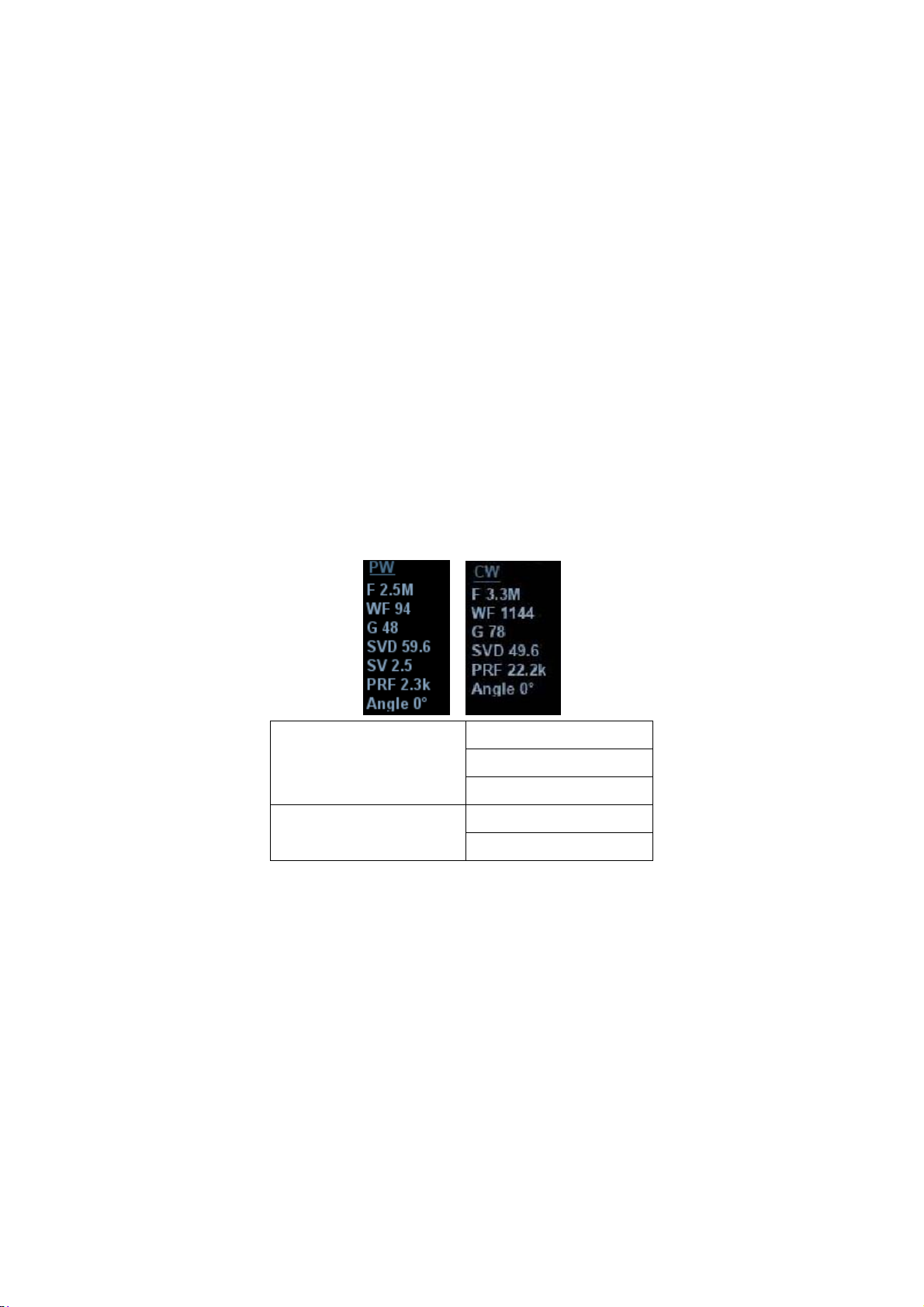
5.6 PW/CW Doppler Mode
PW (Pulsed Wave Doppler) mode or CW (Continuous Wave Doppler) mode is used to
provide blood flow velocity and direction utilizing a real-time spectrum display. The
horizontal axis represents time, while the vertical axis represents Doppler frequency shift.
PW mode provides a function for examining flow at one specific site for its velocity,
direction and features. CW mode proves to be much more sensitive to high-velocity flow
display. Thus, a combination of both modes will contribute to a much more accurate
analysis.
Adjustment items, such as SV, Steer, Duplex, Triplex, iTouch and HPRF, are not available
in CW mode.
5.6.1 Basic Procedures for PW/CW Mode Exam
1. Select a high-quality image during B mode or B + Color (Power) mode scanning, and
adjust to position the area of interest in the center of the image.
2. Press <PW>/<CW> to adjust the sampling line,
z The sampling status will be displayed in the image parameter area in the top-
right corner of the screen as follows:
PW Sampling Line
Adjustment
CW Sampling Line
Adjustment
3. Set the position of the sample line by moving the trackball left and right. Set the SVD
by moving the trackball up and down. Adjust the angle and SV size according to the
actual situation.
4. Press <PW>/<CW> or <Update> again to enter PW/CW mode and perform the
examination. You can also adjust the SV size, angle and depth in real-time scanning.
5. Adjust the image parameters during PW/CW mode scanning to obtain optimized
images.
6. Perform other operations (e.g., measurement and calculation) if necessary.
If “sampling line displaying” is selected, then the screen will display the sampling line all
the time and pressing <M> one will lead to entering M mode directly. For details, see
“5.1.3 Quickly Saving Image Settings” chapter.
SV
Angle
SVD
Angle
CW Focus Depth
5-20 Image Optimization
Page 97

5.6.2 PW/CW Mode Image Parameters
In PW/CW mode scanning, the image parameter area in the top-right corner of the
screen displays the real-time parameter values as follows:
PW Parameter F G PRF WF SVD SV Angle
Meaning Frequency Gain PRF Wall
Filter
CW Parameter F G PRF WF SVD Angle
Meaning Frequency Gain PRF Wall Filter SV Position Angle
During PW/CW mode imaging, the image optimizing menus for B mode and PW/CW
mode are displayed on the touch screen at the same time. If Color mode (Power
mode) is also working, menus for certain modes will be displayed on the touch
screen synchronously, and you can switch between them by clicking the mode tabs.
When you adjust the depth of the B mode image, related changes will occur in the
PW/CW mode image as well.
Most of the parameters are the same for the PW mode and CW modes, so
parameters of both are combined together to be introduced here.
Only phased probes support CW mode.
SV
Position
SV Size Angle
Image Optimization 5-21
Page 98

5.6.3 PW/CW Mode Image Optimization
Gain
Description This function is intended to adjust the gain of the spectrum map. The real-
time gain value is displayed in the image parameter area in the top-right
corner of the screen.
Operations Rotate the [PW] knob clockwise to increase the gain, and counter-
clockwise to decrease it.
The adjusting range is 0-100 in increments of 2.
Effects Increasing the gain will brighten the image and you will see more received
signals. However, noise may also be increased.
SV
Description To adjust the SV position and size of sampling in PW mode, the real-time
value of SV and SVD are displayed in the image parameter area in the
top-right corner of the screen.
SV size Rotate the knob under [SV] on the touch screen to adjust the SV size.
Value: 0.5-20 mm.
SVD Roll the trackball to select the SV depth.
Effects The smaller the SV size, the more accurate the result. More details are
obtained when selecting a large SV size.
CW Focus Position
Description To adjust the CW mode SVD. The real-time focus position value is
displayed in the image parameter area in the top-left side of the screen.
Operation Roll the trackball to select the focus depth.
5-22 Image Optimization
Page 99

Scale
Description This function is used to adjust the speed range of the flow, which is
adjusted using the PRF in the system.
The real-time PRF value is displayed in the image parameter area in the
top-right corner of the screen.
Operations Rotate the knob under the [Scale] item on the touch screen.
Effects Provides a much clearer color flow image.
Use a low PRF to observe low-velocity flows, and a high PRF to observe
high-velocity flows.
Impacts Aliasing may occur if a low-velocity scale is used and high velocities are
encountered.
Low velocities may not be identified when a high-velocity scale is used.
iTouch
Description To optimize image parameters as per the current tissue characteristics for
a better image effect.
Operations Press <iTouch> on the control panel to turn the function on.
Auto-Calculation
Description This function is used to trace the spectrum and calculate the PW/CW
mode image parameters. The results are displayed in the results window.
Tap [Auto Calc] on the touch screen to turn the auto calculation function
on or off.
Auto
Calculation
Parameter
Auto
Calculation
Cycle
Trace Area To set the trace area of the Doppler wave in the spectrum map, applicable
Select parameters in the dialog box prompted by touching [Auto Calc
Param] on the Auto Calculation page.
To set the heart cycle number for auto-calculation.
Tap [Auto Calc Cycle] on the touch screen to select the cycle number, the
adjusting range is 1-5.
for auto calculation, V Max and V Mean display.
To change the trace area, adjust through [Trace Area] item on the touch
screen.
The available selections of trace area are: Above, Below, All.
Invert
Description This function is used to set how the spectrum is displayed.
Operations Turn the function on or off using the [Invert] item on the touch screen.
Select “Auto Invert” in the “[Setup] (F10)Æ [System]Æ[Image]”, so the
spectrum can automatically invert when the color flow is steered to a
certain angle to accommodate the operator’s desire to distinguish the flow
direction.
Image Optimization 5-23
Page 100

Speed
Description This function is used to set the scanning speed of PW mode imaging.
Operations Rotate the knob under the [Speed] item on the touch screen.
There are 6 levels of scan speed available: the smaller the value the faster
the speed.
Effects Changing the speed makes it easier to identify the cardiac cycles and to
detect more details.
T/F Res.
Description This function is used to create a balance between time resolution and
spatial resolution.
Operations Adjust using the [T/F Res.] item on the touch screen.
There are 0-4 levels of T/F Res. values available.
Wall Filter
Description It filters out low-velocity signals to provide effective information, and this
function is used to adjust the filtered frequency. The real-time value is
displayed in the image parameter area in the top-right corner of the
screen.
Operations Select using the [WF] item on the touch screen.
0-6 levels of wall filter function are provided.
Impacts Signals of low-velocity flow may be missing.
Tint Map
Description This function provides an imaging process based on color difference
rather than gray distinction.
Operations Adjust through the [Tint Map] item on the touch screen to select the map.
There are 1-25 color effect maps available. Off represents the function is
disabled.
Gray Map
Description This function applies the gray correction to obtain optimum images.
Operations To select from among the maps, turn the knob under [Gray Map] on the
touch screen. There are 1-25 gray effect maps available.
Display Format
Description To set the display format of PW mode images with B mode images.
5-24 Image Optimization
 Loading...