

Page 1

Datascope’
Page 2

Page 3
INTRODUCTION
Chapters
본
.
Operation
NY
.
Theory
WwW
.
Specifications
.
Repair
MN wR
«
Schematics
.
Parts
A
.
Calibration
.
Preventive
on
A
complete,
chapter a table
FOREWORD
of
Operation
Information
Maintenance
detailed
of
table
contents
of
contents
for
that
begins
chapter
on
page
is
provided.
iii.
Also,
on
the
first
page
of
each
This
Service
personnel,
number
unit
for
and
Predictive
The
information
This
publication
improvements.
replacement
Manual
to
use
0998-00-0444-XX).
part
number
pages
NOTE
Unauthorized
factory
warranty
NOTE:
or
with a local
status
This
produce
(P/N
0070-00-0429)
during
Temperacure
in
may
Any
servicing
of a particular
repair
identification.
this
manual
have
such
changes
and
instructions
may
authorized
is
year
and
NOTE:
Modules.
has
been
updated
to
void
the
Datascope
instrument.
2000
is
intended
calibration
See the
This
been
this
for
inserting
remainder
compliant.
procedures
serial
manual
divided
to
reflect
manual
representative
number
also
includes
into
product
would
or
affixing
of
the
as a guide,
for
the
label
information
the
eight
chapters
design
be
accomplished
them
warranty.
to
determine
for
technically
Accutorr
on
the
rear
on
listed
changes
by
into
the
Check
with
the
qualified
Plus
(part
panel
the
Recorder
above.
and/or
manual.
manual
supplying
the
of
the
Copyright © Datascope
publication
Accutorr
Chapter 1 -
may
Plus,
Service
Operation
not
be
reproduced
Manual
Corp.,
1999.
in
any
Printed
form
in
without
U.S.A.
All
permission
rights
reserved.
of
Datascope
Contents
Corp.
of
this
Page 4

Page 5
TABLE
OF
CONTENTS
INTRODUCTION
10
OPERATION..................
1.1
Introducrdon.................
1.2
Controls
1.2.1
1.2.2
1.2.3
1.2.4
1.3
Operation.
1.3.1
1.3.2
1.3.2.1
1.3.2.2
13.23
1.3.3
1.3.3.1
1332
1.3.3.3
1.3.4
1.3.4.1
1.3.4.2
1.3.4.3 Effects
1.3.4.4
1.3.5
1.3.5.1
1.3.5.2
1353
1.3.5.4
1.3.6
1.3.6.1
1.3.6.2
and
ee
Indicators.
Front
Panel..............................,,..
RearPanel
Predictive
Recorder
..........................................
Serting-Up / Turning
Patient
Selecting
Cuff
Room
Manual
Measurement
NIBP
Cuff
Automatic
(Adaptive
Automatic
Canceling
Changingthelntemalsetting....................
Letter
Start
Aiarms
Setting
Alarm
Howto
Alarms
Bed
To
To
Plus
To
Plus
NIBP
Module
Setup
the
Inflation
Number
NIBP
Pressure
Inflation Time.
of
Changing
on
the
and
Deflate
..
Alarm
Violarions
Mute
and
Letter..........
View
and
View
the
NIBP
View
the
NIBP
with
κ
ον
еее
................................
...........................
Thermometer
.............................
and
Room/Bed
Patient
Pressure . ........................
and
Measurements
Information.
Limit
Adjustment
Inflation)
NIBP
an
Measurements
Automatic
Interval
Functions.
ν
Limits
Alarms
Changing
Delete
Stored
«νεο
Stored
with
Trend
Trend
Module
Power
Size
.......................
Bed
Letter
......................
Fail Safe
...........................
of
Cuff
...........................
NIBP
the
Room
Setting
ων ω ων ω νο
..........................
.............................
..........................
the
Room
2...
Stored
Measurements
ν
εν
Measurements
Screen
Screen
and
.................
On..................
Assignment...........
...................
and
General
Inflation
(Interval
Measurement
Number
....................
.....................
ον
Number
Data
(Trend
on
εν
ων ν νο
on
and
the
SpO2................
NIBP
Pressure
Mode)
and
/or
ων
ενω
ων ως
and/or
ee
Mode).......
the
Accutorr
κενο
the
Accutorr
ων
Accutorr
ーー
еенньня
4.6...
.....
........
Bed
φως
ως
eee
εν
εως
Plus
Accutorr
Introduction
Plus
Service
Manual
iii
Page 6
1.3.6.3
1.3.7
1.3.8
1.3.9
1.3.10
1.3.10.1
1.3.10.2
1.3.10.3
13.11
1.3.11.1
1.3.11.2
1.3.11.3
1.3.11.4
1.3.12
13.13
1.3.14
1.3.15
1.3.16
1.3.17
1.3.18
1.3.19
To
Delete
Models
Setting
Setting
Display
SpO2
Datascope
Sequence
Oximetry*
Sequence
Oximetry*
Temperature
Predictive
How
How
Storing
Recorder
How
Battery
User
Status
How
RecorderModules.............................
Placement
Placement
the
Stored
of
the
Accutorr
the
Alarm
the
LCD
Time
Out
Measurements
Pulse
for
Establishing
..................................
for
Establishing
.................................
Measurement
Thermometer
to
Apply
to
Take
Oral,
Temperature
(optional)............................
to
Set
the
Operation...............
Configuration............................
and
Error
to
Attach
of
the
of
Recorder
Measurements
Plus
.....................
Volume
Contrast
Mode........................
Oximetry
Probe Cover
Rectal,
and
(View
(Accutorr
Sensors
SpO2
SpO2
(optional)
Measurements
(PTM)................
and
Measurements
Clock
(Date
and
Codes
Optional
.........................
Thermometer
Quick
Reference
Paper
on
all
Beep
Volume
Angle
Plus
with
with
Axillary
Adjustment)
model
................
with
Nellcor®
Masimo®
..............
............
Temperatures . 1-44
...............
Time).............
and
Card
............
Loading
Label
........
SpO2).
Pulse
Pulse
ω
εν κ ων
.........
..
1-29
1-30
1-31
1-32
1-33
1-33
1-37
1-40
1-43
1-43
1-43
1-45
1-46
1-47
1-48
1-49
1-51
1-52
1-53
1-54
iv
Revised
2.0
THEORY
2.1
Block
2.2
Detailed
2.2.1
2.2.1.1
2.2.1.2
2.2.1.3
2.2.2
2.2.3
2.2.4
2.2.5
2.2.6
2.2.7
2.2.8
2.2.9
12/20/00
2.2.10
OF
OPERATION
Diagrams
Circuit
LED/CPU
Hardware
Software
Detailed
NIBP
Recorder
Predicrive
SpO2
Main
Communication
LCD
Descriptions.
Module,
Module
Power
Inverter
Nelicor®
Theory
Interface
......................................
Module,
Overview
Overview
Hardware
Module
Thermometer
MP
of
Operation
Nellcor®
...........................
...........................
0670-00-0650-03,-04..........
...........................
............................
Description.
Linear
(Accutorr
Bleed
.............................
Plus
..................
.....................
Module
.................
with
SpOz
only)
.......
Supply............................
Board
.........................
Module - 0670-00-0649 . ............
304
SpO>
Circuit
...........................
Board
Board
Theory
of
Operation
Accutorr
.......
Plus
2-1
2-1
2-2
2-9
2-9
2-9
2-10
2-17
2-20
2-21
2-22
2-25
2-26
2-28
Service
Manual
Introduction
2-29
2-30
Page 7
2.2.11
2.2.12
3.0
SPECIFICATIONS
3.1.
PerformenceSpecificatilons..............................
3.2
Safety
3.3
Physical
3.4
Environmental
3.5
Electrical
3.6
Agency
3.7
Electromagnetic
4.0
REPAIR
4.1
Introduction.
4.2
Safety
4.3
General
4.4
Test
4.5
Troubleshooting
451
4.5.2
4.5.3
45.4
4.6
Disassembly
4.6.1
4.6.2
4.6.3
4.6.4
4.6.5
4.6.6
4.6.7
4.6.8
4.6.9
4.6.10
4.6.11
4.6.12
4.6.13
4.6.14
4.6.15
4.6.16
Masimo
Masimo
Characteristics
Characteristics
Ratings
Compliance
SET?
Interface
Characteristics
.........................,.........
Compatibility.
INFORMATION
........................................
Precautions.
Troubleshooting
Equipment
Isolating
Isolating
Isolating
Clinical
Removal
Removal
Removal
Removal
Removal
Removal
Removal
High
Removal
Removal
Removal
Removal
Lead
Removal
Thermal
Thermometer,
AccuTemp
module)
AccuTemp
....................................
Required
(Problem
the
the
the
Issues.
Instructions
of
of
of
of
of
of
of
Voltage
of
of
of
and
Acid
of
Printer
....................................
Technology.
Board
.....................
Theory
of
Operation
...........................,......
..................................
................................
...........................
..........................
............................
Guidelines
.......
Isolation)
Problem,
Problem
Problem
the
che
the
the
the
the
the
the
the
the
Replacement
or
Li-lon
the
IR,
IR
with
...............................
...............................
Rear
Housing
Front
Keyboard
CPU
NIBP
Power
Motor
Assembly
NIBP
LCD
Dispiay
SpOz
Battery
AC
Input
(Optional
Predictive
Infrared
Mounting
......................
A...
......................
System
within
Bezel
Board
Circuit
Supply
Filter
Air
Circuit
Level
...............
the
Main
Unit.........
Optional
(2)...................
Assembly
Assembly
(35)
Pump
of
Receptacle
Module)
(Optional
Thermometer
Cradle..................
Accessory
(27)
................
(4).............
Assembly
Assembly
and
LCD
....................
Assembly
Assembly
Board
.....................
(40)............
the
Internal
Assembly
...............
Module)
Modules.
(8)
...........
(30)
(41)
(37)
and
Back
Sealed
(optional
........
ーー
. .
........
........
......
Light
(5)
(16). . .
........
2-31
2-32
3-1
3-1
3-6
3-7
3-7
3-7
3-8
3-8
4-1
4-1
4-2
4-2
4-3
4-4
4-5
4-5
4-6
4-6
4-9
4-9
4-9
4-9
4-10
4-10
4-10
4-11
4-11
4-11
4-11
4-12
4-12
4.12
4-13
4-13
4.13
Accutorr
Introduction
Plus
Service
Manual
.
Revised
12/20/00
Page 8
4.6.17
Communication
Board
(45)......................
4-13
ASSEMBLY
5.0
6.0
REPLACEMENT
6.1
Introduction.
6.2
Available
Product
6.3
6.4
ExchangeProgram............................
Replacement
6.5
6.6
Ordering
6.7
Abbreviations.
6.8
Isometric
6.8.1
6.8.2
6.8.3
6.8.4
6.8.5
6.8.6
Circuit
6.9
AND
........................................
Replacement
Variations
Parts
Information.
Drawings
Accutorr
Recorder
Predictive
Mobile
Mobile
Mounting
Board
SCHEMATIC
PARTS
and
Pricing
................,......................
and
Plus
Module
Temperature
Stand
Stand
Options
Parts
Lists.
..,...............,..........
Parts
Options
Information
.................................
Parts
Isometric
Isometric
Type 1 (Gray
Type 2 (Black
...............................
DIAGRAMS
and
Sub-Assemblies
..........................
....................
List
........................
Parts
List (All
Parts
List..............
Module
............................
Isometric
Base)
Assembly
Base)
............
............
Models)
Parts
Assembly
ων
......
List.
Parts
List . 6-17
Parts
5-1
6-1
6-1
6-1
6-1
ων
6-1
6-2
6-2
6-3
6-5
6-5
6-13
. .
6-15
List . 6-19
6-19
6-21
7.0
CALIBRATION...............
7.1
Introduction.
7.2
Warnings
7.3
Test
74
Power-Up
Service
7.5
751
7.5.2
753
7.5.4
7.5.5
7.5.6
7.5.6.1
7.5.7
7.5.8
7.5.9
7.5.10
7.5.11
7.5.12
Equipment
........................................
and
Guidelines.
and
Special
Sequence,
Diagnostics.
Introduction
Software
Keypad
LED
Communications
Recorder
Recorder
Pump
Leak
Over
Pulse
Pulse
Main
(118,
Internal
...................................
Version
Test
Test
(2a,
Test
Print
Test
(5)........:........................
Test
(7).................................
Pressure
Channel
Channel
Pressure
11b,11c).........................,..,..
esse
..............................
Tools
Required.
Testing.
(Hidden
.................................
2b).............................
(4)
Head
Test
DC
Average
Transducer
Key)......................
Test
(0a,
Ob)....................
Test
(3a,
3b)
.............................
Adjustment
(8a,
8b,
Offset
Test
Noise
Verification
................
.....................
...................
.................
8c)...................
(9a,
9b,
9c)
..........
Test
(10a,
10b,
10c)....
Test
7-1
7-3
7-3
7-3
7-4
7-4
7-4
7-5
7-6
7-7
7-7
7-7
7-8
7-8
7-9
7-10
7-10
7-11
7-11
vi
Revised
12/20/00
Accutorr
Plus
Service
Manual
Introduction
Page 9
7.5.13
7.5.14
7.5.15
7.5.16
7.5.17
7.6
Predictive
7.6.1
7.62
7.63
7.6.4
7.6.5
7.7
Battery
7.74
7.7.2
7.8
NIBP
7.9
Trend
7.10
SpO2
Verification
Using
Check
Main
Over
Battery
Thermometer
Temperature
Predicrive
Water
System
Temperature
Thermometer
Low
Battery
Test
for
Low
Set
the
Normal
Memory
Normal
Operation
of
Accutorr
the
“Cufflink”
Over
Pressure
Pressure
Pressure
Selection
Bath
Calibration
Accutorr
Battery
Current
Operation
Initialization
Transducer
Transducer
(13)..........................
Verification
Accuracy
Temperature
Method
Verification
................................
Sensing
Plus
Indicator..........................
Time
...............................
(Accutorr
Plus
Pneumatic
NIBP
Reference
...........................
Procedure
...........................
...........................
............................
Emulator
(12a,
Calibration
Calibration..............
and
Calibration..........
Verification
Simulator
....................
Test,
Infrared
..........................
Plus
with
Performance,
(11d)
.........
12b,
12c).......
(llc)
.........
with
the
................
SpO2
only).
......
7-11
7-12
7-12
7-13
7-13
7-14
7-14
7-15
7-15
7-16
7-17
7-18
7-18
7-18
7-19
7-20
7-20
8.0
PREVENTIVE
8.1
Introduction.........................................
8.2
Limitations
8.3
Preventive
8.3.1
8.3.2
Mechanical
(One
Electrical
(One
MAINTENANCE.............,.........
of
Physiological
Maintenance
and
Year
Interval)............................
Safety
Year
Interval)............................
Simulators
Schedule............
Physical
and
Performance
....................
Visual
Inspection
Checks
l
8-1
8-1
8-1
8-2
8-2
8-2
Accutorr
Introduction
Plus
Service
Manual
Revised
12/20/00
vii
Page 10

Page 11
1.0
OPERATION
CONTENTS
1.1
Inttoduction..
1.2
Controls
13
Operatlon................
1.1
This
section
of
the
Accutorr
Plus
NIBP
encouraged
complete
OF
THIS
CHAPTER
and
Indicators
INTRODUCTION
of
the
Service
Plus
NIBP,
with
Trend
Screen
to
refer
to
the
details.
Page
ν
νεο
νο
νεο
................................
0.
eee
Manual
Operating
the
Accutorr
and
(P/N
0070-00-0429)
Plus
NIBP
SpO2
functions
Instructions,
ών
with
and
operation.
P/N
0070-00-0428,
οω
νο
is
provided
Trend
ω ο
νε
ον
as a review
Screen
and
The
reader
for
νο
1-1
1-3
1-17
the
is
more
Accutorr
Accutorr
Chapter 1 -
Plus,
Service
Operation
Manual
Revised
06/25/99
1-1
Page 12

Accutorr
Chapter 1 -
Plus,
Service
Operation
Manual
Page 13
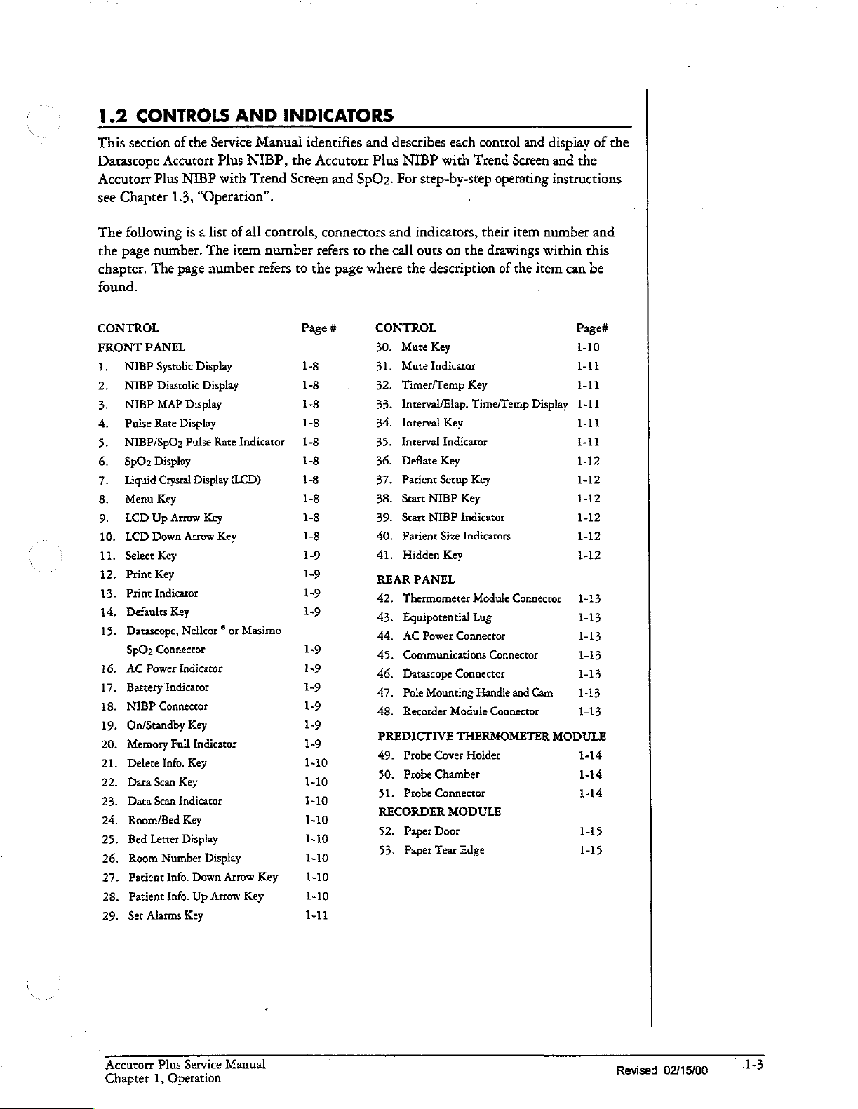
1.2
CONTROLS
This
section
Datascope
Accutorr
see
The
the
chapter.
Plus
Chapter
following
page
number.
The
found.
CONTROL
FRONT
16.
17.
18.
19.
20.
21.
22.
23.
24.
25.
26.
27.
28.
29.
NIBP
는
NIBP
NIBP
Pulse
EN
NIBP/SpO2
9ΡΟ2
Liquid
Menu
LCD
vom
.
LCD
은
ピロ
.
Select
=
.
Print
N
Print
Defaults
du
.
Datascope,
o
U
SpO2
AC
Battery
NIBP
On/Standby
Memory
Delete
Data
Data
Room/Bed
Bed
Room
Patient
Patient
Set
PANEL
Systolic
Rate
Display
Up
Down
Key
Indicator
Connector
Power
Scan
Scan
Letter
Alarms
of
the
Accutorr
NIBP
1.3,
“Operation”.
is a list
page
Display
Diastolic
MAP
Display
Display
Pulse
Crystal
Display
Key
Arrow
Arrow
Key
Key
Nellcor ® or
Indicator
Indicator
Connector
Key
Full
Indicator
Info.
Key
Key
Indicator
Key
Display
Number
Info.
Down
Info.
Up
Key
AND
Service
Plus
with
of
The
item
number
Display
Rate
Indicator
(LCD)
Key
Key
Display
Arrow
Arrow
Manual
NIBP,
Trend
all
controls,
number
refers
Masimo
Key
Key
INDICATORS
identifies
the
Accutorr
Screen
connectors
refers
to
the
Page
1-8
1-8
1-8
1-8
1-8
1-8
1-8
1-8
1-8
1-8
1-9
1-9
1-9
1-9
1-9
1-9
1-9
1-9
1-9
and describes
Plus
and
SpOo.
to
the
page
where
#
19
1-10
1-10
1-10
1-10
1-10
1-10
1-10
1-10
1-11
NIBP
For
step-by-step
and
indicators,
call
outs
the
description
CONTROL
30.
Mute
Key
31.
Mute
Indicator
32.
Timer/Temp
33.
Interval/Elap.
34.
Interval
35.
Interval
36.
Deflate
37.
Patient
38.
Start
NIBP
39.
Scart
NIBP
40.
Patient
41.
Hidden
REAR
PANEL
42.
Thermometer
43.
Equipotential
44,
AC
Power
45.
Communications
46.
Datascope
47.
Pole
Mounting
48.
Recorder
PREDICTIVE
49.
Probe
50.
Probe
51.
Probe
RECORDER
52.
Paper
53.
Paper
each control
with
Trend
and
Screen
operating
their
item
on
the
drawings
of
the
item
Key
Time/Temp
Key
Indicator
Key
Setup
Key
Key
indicator 1-12
Size
Indicators
Key
Module
Lug
Connector
Connector
Handle
Module
THERMOMETER
Cover
Holder
Chamber
Connector
MODULE
Door
Tear
Edge
Display
Connector
Connector
and
Cam
Connector
display
and
of
the
the
instructions
number
within
can
Page#
1-10
1-11
1-11
1-11
1-11
1-11
1-12
1-12
1-12
1-12
1-12
1-13
1-13
1-13
1-13
1-13
1-13
1-13
MODULE
1-14
1-14
1-14
1-15
1-15
and
this
be
Accutorr
Chapter
Plus
Service
1,
Operation
Manual
Revised
02/15/00
1-3
Page 14
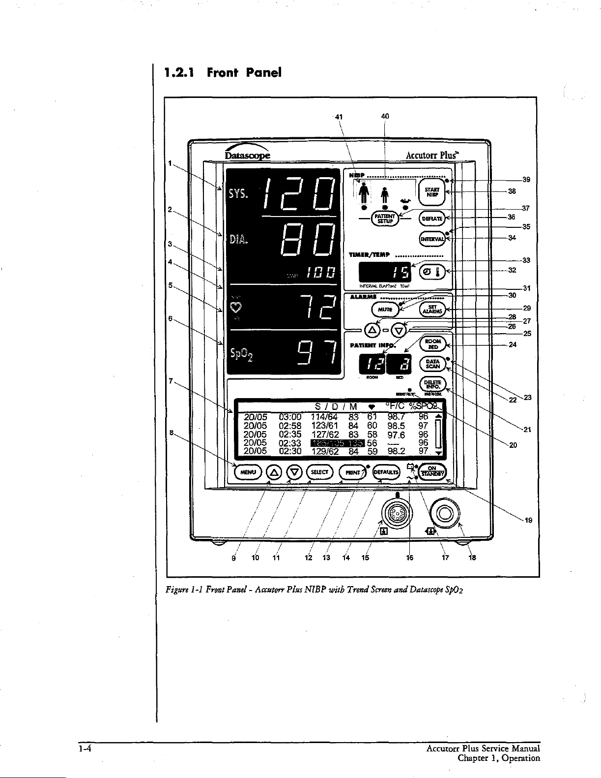
1.2.1
Front
Panel
,
2
3
a
5
。
7
4
\
|
+
\
\
TIMER/TEMP
p
一
PATIENT
INTERVAL
Os)
一
Dr
40
ELAPTINE
MUTE
of
INFOS
Accutotr
.
TEMP
eo
A
CSD
a
。
o
SET
Plus“
AS
4
38
37
36
34
32
30
ον
26
24
2223
39
35
23
31
29
고
o
la
8
Figure
1-1
Front
Panel - Accutorr
Plus
123/61
E
NIBP
162.
with
83
84
e
BA
Trend
63
60
58
=
Screen
O8.
98.5
97.6
2
and
Datascope
2
Sp02
24
19
Accutorr
Chapter
Plus
Service
1,
Operation
Manual
Page 15
M
A
|
2
3
4
5.
s
7
i
8
e”
Datascope
coto
:
02:58
02:35
:
\
4
123/61
127/62
co
62
83
84
83
84
40
>
Accutorr
©
8.
60
985
58
976
1732
EQ
59
982
Plus
97
96
96
97
>
기
39
38
37
35
33
32
31
30
29
28
28
25
24
22-28
21
20
=
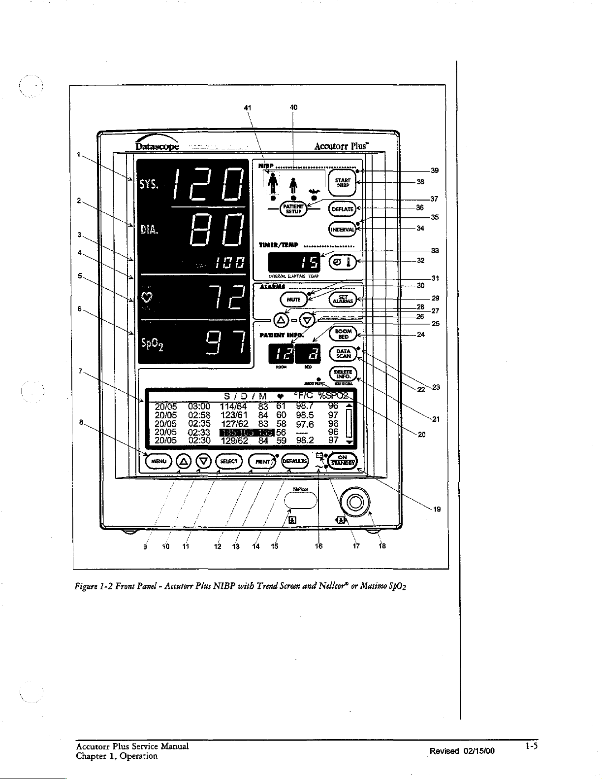
Figure
1-2
Front Panel - Accutorr
Accutorr
Chapter
Plus
Service
1,
Operation
Manual
Plus
NIBP
with
Trend
Screen
and
Nellcor®
or
Masimo
SpO2
19
„Revised
02/15/00
1-5
Page 16
Accutorr
圖
ЧИ
LI
LT
--
amm,
LL
či
σα
114/64
123/61
12762
83.
Plus”
=
39
37
36
32
30
26
24
20
31
27
25
23
21
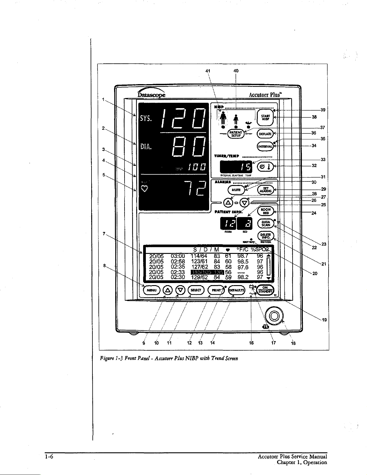
Figure
1-3
Front
Panel - Accutorr
Plus
NIBP
with
Trend
Screen
19
Accutorr
Chapter
Plus
Service
1,
Operation
Manual
Page 17
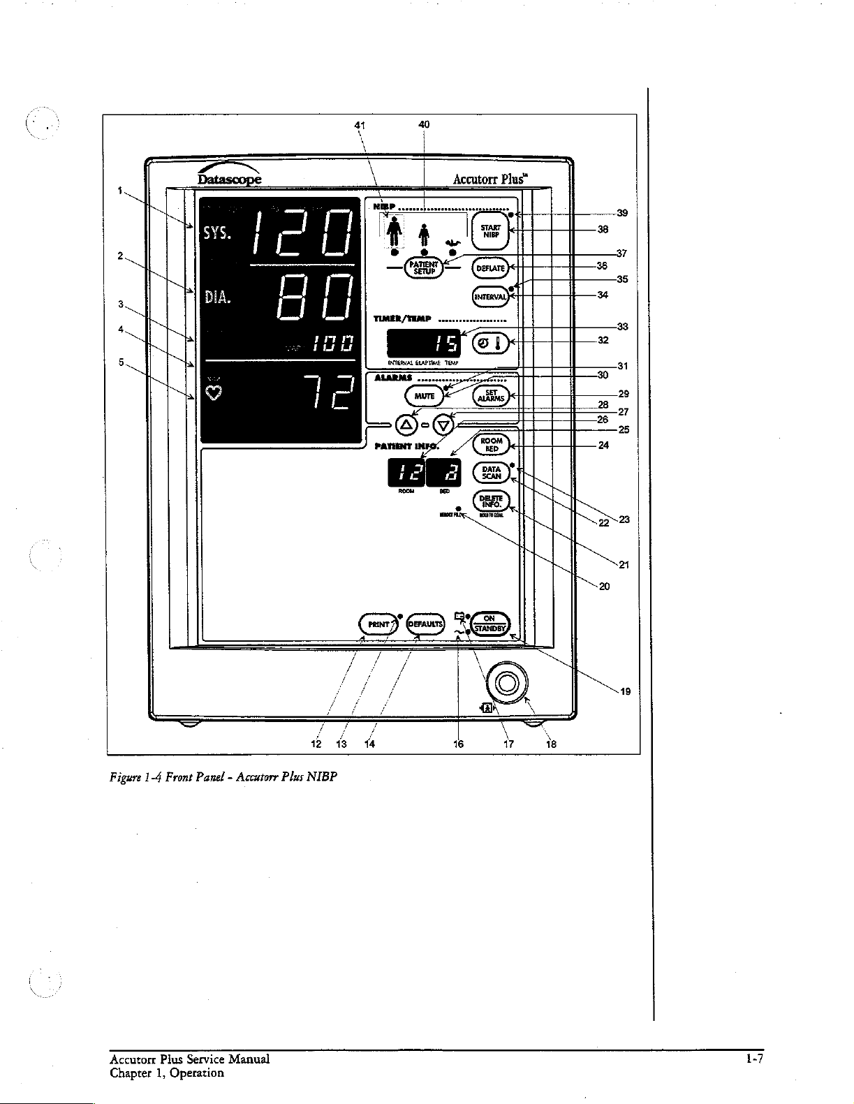
40
Accutorr
Plus”
Figure
1-4
Front
Panel - Accutorr
Plus
2
NIBP
43 14
16 17
Accutorr
Chapter
Plus
Service
1,
Operation
Manual
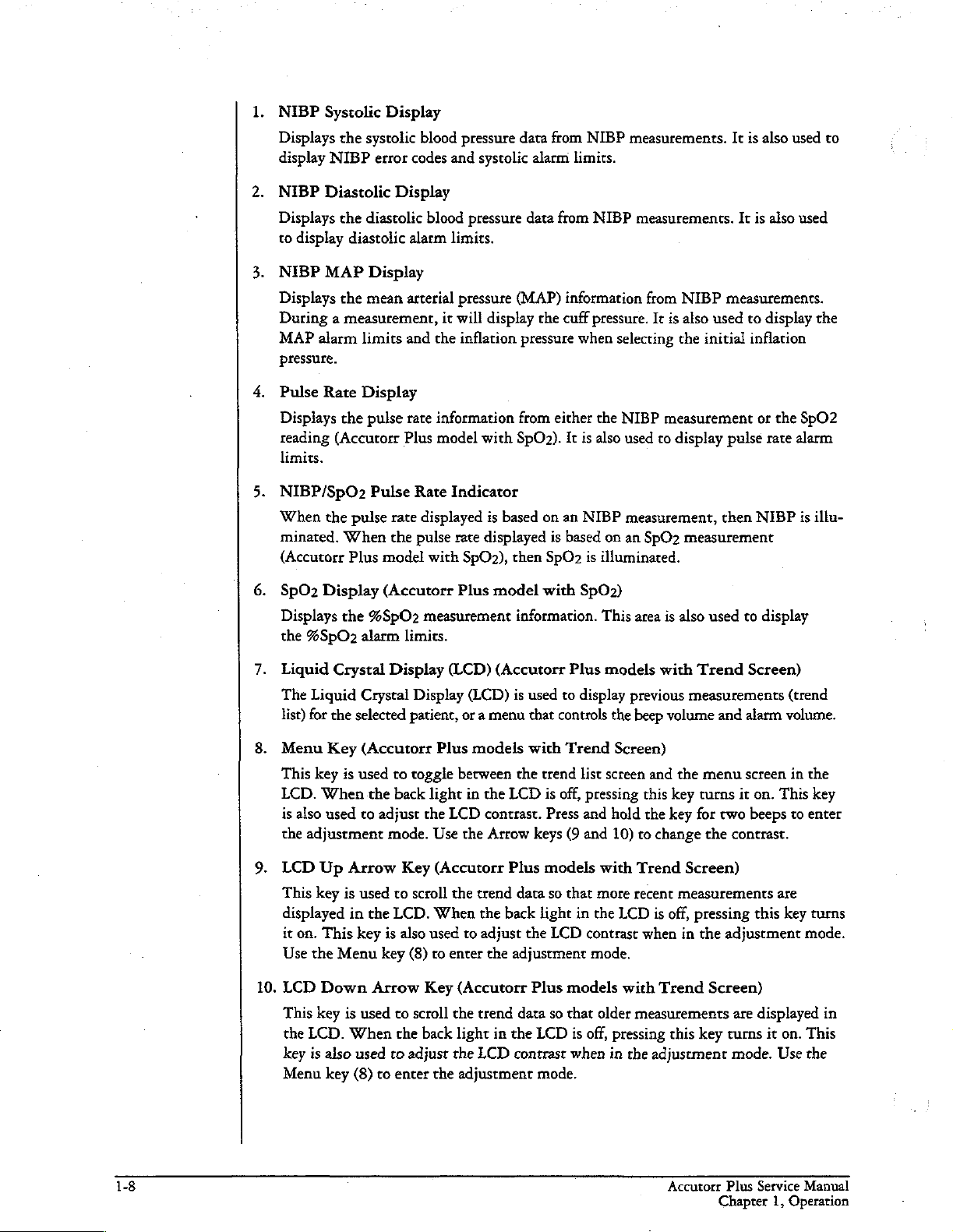
Page 18
NIBP
Displays
display
NIBP
Displays
Systolic
NIBP
Diastolic
to
display
NIBP
MAP
Displays
During a measurement,
MAP
alarm
Display
the
systolic
error
Display
the
diastolic
diastolic
Display
the
mean
limits
blood pressure
codes
blood
alarm
arterial
and
pressure.
Pulse
Rate
Display
Displays
reading
limits.
the
pulse
(Accurorr
rate
Plus
and
systolic
pressure
limits.
pressure
it
will
display
the
inflation
information
model
with SpOz).
data
from
alarm
data
from
(MAP)
from
information
the
cuff
pressure
either
It
NIBP
limits.
NIBP
pressure.
when
selecting
the
NIBP
is
also
measurements.
measurements.
from
NIBP
It
is
also
used
the initial
measurement
used
to
display
It
is
also
used
It
is
also
used
measurements.
to
display
inflation
or
pulse
rate
the
the
SpO2
alarm
to
NIBP/SpO2
When
the
pulse
minated.
(Accutorr
SpOz
Displays
the
Liguid
The
list)
Menu
This
LCD.
is
also
the
LCD
This
displayed
it
Use
When
Plus
Display (Accutorr
the
%SpOz
Liguid
for
key
adjustment
on.
the
Crystal
the
Key
is
When
used
Up
key
is
This
Menu
alarm
Crystal
selected
(Accutorr
used
to
Arrow
used
in
key
Pulse
rate
the
model
%SpO2
Display
to
the
back
adjust
mode.
to
the
LCD.
is
also
key
Rate
Indicator
displayed
pulse
rate
with
Plus
measurement
limits.
(LCD)
Display
patient,
toggle
Key
scroll
(8)
or a menu
Plus
berween
light
the
LCD
Use
the
(Accutorr
the
When
used
to
enter
is
based
displayed
SpO2),
model
(Accutorr
(LCD)
models
in
the
contrast.
Atrow
trend
the
back
to
adjust
the
on
an
NIBP
is
based
then
SpO
is
with
SpO2)
information.
Plus
is
used
to
display
that
controls
with
Trend
the
trend
list
LCD
is
off,
pressing
Press
and
keys
(9
and
Plus
models
data
so
that
light
in
the
LCD
contrast
adjustment
measurement,
on
an
SpO2
illuminated.
This
area
is
models
the
screen
hold
10)
with
more
the
mode.
with
previous
beep
Screen)
and
this
the
to
change
Trend
recent
LCD
is
when
volume
then
measurement
also
used
to
Trend
measurements
the
key
turns
key
for
and
menu
it
two
the
contrast.
Screen)
alarm
screen
Screen)
measurements
off,
pressing
in
the
adjustment
NIBP
display
volume.
on.
This
beeps
are
this
key turns
is
illu-
(trend
in
the
key
to
enter
mode.
10.
LCD
This
the
LCD.
key
Menu
Down
key
is
is
When
also
key
Arrow
used
used
(8)
to
to
scroll
the
to
adjust
enter
Key
the
back
the
the
(Accutorr
trend
data
light
in
the
LCD
contrast
adjustment
Plus
so
LCD
mode.
models
that
older
is
off,
when
with
Trend
measurements
pressing
in
this
the
adjustment
Screen)
are
key
turns
mode.
displayed
it
on.
This
Use
the
in
Accutorr
Chapter
Plus
Service
1,
Operation
Manual
Page 19
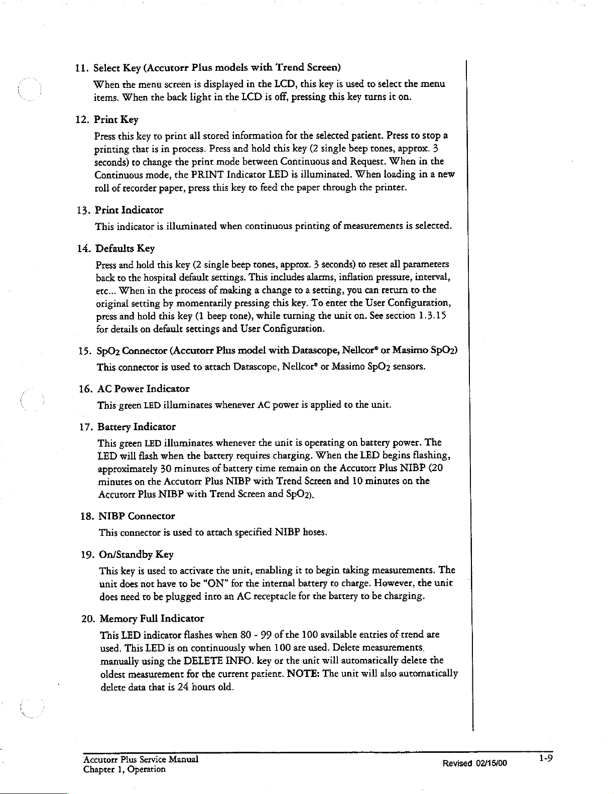
11.
Select
When
items,
12.
Print
Press
printing
seconds)
Continuous
roll
13.
Print
This
14.
Defaults
Press
back
etc...
original
press
for
15.
SpO2
This
Key
(Accutorr
the
menu
When
Key
this
key
that
to
change
mode,
of
recorder
Indicator
indicator
Key
and
hold
to
the
hospital
When
setting
and
hold
details
on
Connector
connector
screen
the
back
to
print
is
in
process.
the
the
paper,
is
illuminated
this
key
default
in
the
process
by
momentarily
this
key
default
(Accutorr
is
used
Plus
models
is
displayed
light
in
all
stored
Press
print
mode
PRINT
press
this
when
(2
single
settings.
of
making a change
(1
beep
settings
to
attach
and
Plus
with
in
the
the
LCD
is
information
and
hold
berween
Indicator
key
beep
pressing
tone),
model
Datascope,
LED
to
feed
continuous
tones,
This
includes
while turning
User
Configuration.
with
Trend
LCD,
off,
this
this
Screen)
this
key
is
pressing
for
key
Continuous
is
the
paper
printing
approx. 3 seconds)
to a setting,
key.
Datascope,
Nellcor®
this
the
selected
(2
single
and
illuminated.
through
of
alarms,
To
the
inflation
enter
unit
or
Masimo
Nellcor®
used
to
select
key
turns
it
on.
patient.
beep
Request.
When
measurements
you
the
on.
tones,
the
printer.
to
reset
pressure,
can
User
See
SpO2
Press
approx.
When
loading
all
return
Configuration,
section
or
Masimo
sensors.
the
menu
to
stop
a
3
in
the
in a new
is
selected.
parameters
interval,
to
the
1.3.15
SpO2)
16.
AC
Power
This
green
17.
Battery
This
green
LED
will
approximately
minutes
Accutorr
18.
NIBP
This
connector
19.
On/Standby
This
key
unit
does
does
need
20.
Memory
This
LED
used.
manually
oldest
delete
Indicator
LED
illuminates
Indicator
LED
illuminates
flash
when
30
on
the
Accutorr
Plus
NIBP
Connector
is
Key
is
used
to
not
have
to
be
plugged
Full
Indicator
indicator
This
LED
is
using
the
measurement
data
that
is
the
battery
minutes
used
activate
to
with
to
be
of
Plus
Trend
attach
“ON”
into
flashes
on
continuously
DELETE
for
the
24
hours
whenever
whenever
requires
battery
NIBP
Screen
specified
the
unit,
for
the
an
AC
when
80 - 99
when
INFO.
current
old.
patient.
AC
power
the
unit
is
charging.
cime
remain
with
Trend
and
SpOn).
NIBP
enabling
internal
receptacle
key
of
the
100
or
the
it
battery
for
are
NOTE:
is
applied
operating
When
on
the
Accutorr
Screen
and
hoses.
to
begin
to
the
battery
100
available
used.
Delete
unit
will
The
co
the unit.
on
battery
the
LED
10
taking
charge.
to
entries
automatically
unit
will
power.
begins
Plus
NIBP
minutes
measurements.
be
measurements.
on
However,
charging.
of
trend
delete
also
automatically
The
flashing,
(20
the
The
the
unit
are
the
Accutorr
Chapter
Plus Service
Operation
1,
Manual
Revised
02/15/00
1-9
Page 20
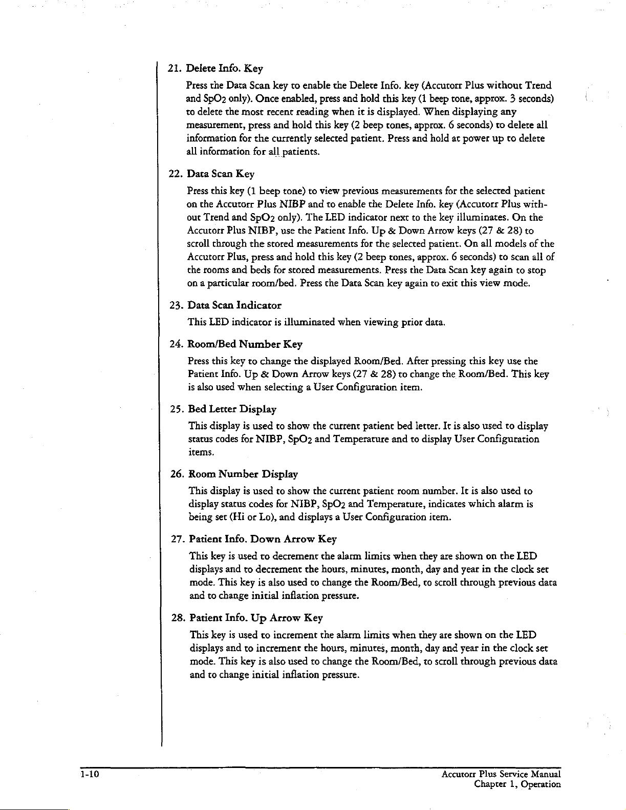
21.
Delete
Press
the
and
SpO2
to
delete
measurement,
information
all
information
22.
Data
Scan
Press
this
on
the
out
Trend
Accutorr
scroll
through
Accutorr
the
rooms
on a particular
23.
Data
Scan
This
LED
24.
Room/Bed
Press
this
Patient
is
also
Info.
Key
Data Scan
only).
the
most
press
for
for
Key
key
(1
Aceutorr
and
SpO2
Plus
NIBP,
the
Plus,
press
and
beds
room/bed.
Indicator
indicator
Number
key
to
Info.
Up & Down
used
when
key
to
enable
Once
enabled,
recent
reading
and
hold
the
currently
all
patients.
beep
tone)
to
Plus
NIBP
and
only).
The
use the
stored
measurements
and
hold
for
stored
Press
is
illuminated
Key
change
the
Arrow
selecting a User
the
Delete
press
and
hold
when
it
is
this
key
(2
beep
selected
Patient
this
measurements,
displayed
patient.
view
previous
to
enable
LED
indicator
Info.
for
key
(2
beep
the
Data
Scan
when
viewing
Room/Bed.
keys
(27 & 28)
Configuration
the
Info.
key
this
key
displayed.
cones,
approx. 6 seconds)
Press
and hold
measurements
Delete
next
to
Up & Down
the
selected
tones,
Press
the
key
again
prior
After
to
change
item.
(Accutorr
(1
beep
When
Info.
the
Arrow
patient.
approx. 6 seconds)
Data
to
data.
pressing
Plus
tone,
approx. 3 seconds)
displaying
at
power
for
the
selected
key
(Accucorr
key
illuminates.
keys
On
Scan
key
exit this
this
the
Room/Bed.
without
up
(27 & 28)
all
again
view
key
any
to
delete
to
delete
patient
Plus
On
models
to
scan
to
mode.
use
This
Trend
all
with-
the
to
of
the
all
of
stop
the
key
25.
26.
27.
28.
Bed
This
Room
Letter
display
status
codes
items,
Number
This
display
display
being
Patient
This
displays
mode.
and
status
set
key
This
to
change
Info.
Patient
This
key
displays
mode.
This
to
change
and
Display
is
for
is
codes
(Hi
or
Down
is
used
and
to
key
Info.
Up Arrow
is
used
and
to
key
used
to
show
NIBP,
used
decrement
initial
increment
initial
Display
to
for
Lo),
and
Arrow
to
decrement
is
also
inflation
to
increment
is
also
inflation
SpO2
show
NIBP,
used
used
the
current
and
Temperature
the
current
SpO2
and
displays a User
Key
the
alarm
the
hours,
minutes,
to
change
pressure.
the
Key
the
alarm
the
hours,
minutes,
to
change
pressure.
the
patient
patient
Configuration
limits
limits
bed
letter.
and
to
display
room
number.
Temperatute,
when
they
month,
Room/Bed,
when
they
month,
Room/Bed,
It
is
User
indicates
item.
are
shown
day
and
to
scroll
through
are
shown
day
and
year
to
scroll
through
also
used
to
Configuration
It
is
also
used
which
alarm
on
the
year
in
the
previous
on
che
in
the
previous
display
to
is
LED
clock
LED
clock
set
data
set
data
1-10
Accutorr
Chapter
Plus
Service
1,
Operation
Manual
Page 21

29.
Set
This
alarms
Systolic
Pulse
press
use
the
30.
Mute
Press
new
hold
this
31.
Mute
This
and
32.
Timer/Temp
„This
the
Accutorr
time
Alarms
key
the
alarm
alarm
(2
key
LED
when
Interval/Elap.
Key
is
used
to
be
changed.
Hi,
Systolic
Rate
Lo,
returns
Patient
values.
Key
this
key
is
beep
again
Indicator
indicator
the
key
is
used
Plus
of
the
measurement.
to
select
$pO2
the
unit
Info.
(one
beep
detected
tones,
(1
beep
alarm
Key
to
Time/Temp
NIBP,
the
NIBP
and
Repeated
Lo,
Diastolic
Hi
and
to
normal
Up & Down
tone),
during
approx. 3 seconds)
tone),
is
illuminated
volume
switch
press
presses
Hi,
Diastolic
SpO2
Lo.
operation.
Arrow
to
silence
the 2 minutes, a new
to
activate
when
is
set
to
OFF.
between
this
viewing
Display.
key
to
SpO2
(Accutorr
of
this
key
Lo,
After
che
Once
keys
(27 & 28)
the
current
to
permanently
alarm
tones.
the
alarm
the
When
viewing
switch
between
Plus
model
sequences through
Map
Hi,
Map
last
available
the
desired
alarm
alarm
silence
tone
has
elapsed
parameter,
parameter
to
increment
tone
tone
all
been
time
or
stored
viewing
will
measurements
with
SpO2)
the
choices
Lo,
Pulse
Rate
the
next
is
flashing,
or
decrement
for 2 minutes.
sound,
alarm
silenced
the
the
temperature
Press
tones.
permanently
temperature
on
of
Hi,
Ifa
and
Press
in
the
and
33.
Interval/Elap.
This
displays
Time
is
the
current
probe
is
Either
"85.0"
the
Predictive
number
will
no
longer
is
used,
thermometer
time
and
34.
Interval
Press
to
measurement
set
to
display
240
minutes,
in
the
Interval/Elap.
enter
the
have
elapsed
35.
Interval
When
an
‘When
Time/Temp
the
time,
illuminated).
Interval
removed
increases.
the
temperature
date
Key
enter
interval
Indicator
interval
the
interval
setting
from
its
(°F)
or
"29.4"
thermometer
When
flash
and a beep
is
placed
when
setting
the
set
cycles.
To
graphics),
repeatedly
Time/Temp
setting
without
setting
mode
Display
in
minutes
When
time
the
(Interval
holder,
(°C)
is
the
final
tone
is
not
back
into
the
interval
sequence
CONT
press
or,
the
pressing
is
selected,
is
activated
since
the
last
successful
Interval
the
will
taking a measurement,
temperature
displayed
its
clock.
(Continuous),
the
Interval
Display
displayed
the
key
is
illuminated).
Elap.
Time
display;
is
generated.
until
holder.
mode.
through
Patient
This
An
the
key.
the
setting
Info.
except
the
Interval
for
is
pressed,
When
changes
this
is
measurement
When
after
display
interval
interval
1,
2.5,
When
TIMER/TEMP
will
Up
Off,
Indicator
NIBP
the
Elap.
the
to
Temp
an
internal
the
display
is
the
AccuTemp
the
measurement
will
also
is
set for
choices
5,
10,
the
desired
be
entered
or
Down
the
Interval
illuminates
measurement
Time
Predictive
(Temp
is
illuminated).
self test
will flash
determined,
IR
thermometer
is
show
the
automatic
of:
OFF
(
15,
20,
30,
interval
key
may
be
when
arrow
keys
Indicator
continuously.
(Elap.
changes
thermometer
feature.
taken
60,
is
15
(27 & 28).
to
As
as
the
the
display
and
current
NIBP
,
when
120
and
displayed
pressed
seconds
flashes.
the
to
Accutorr
Chapter
Plus
Service
1,
Operation
Manual
Revised
06/25/99
1-11
Page 22

36.
37.
Deflate
Press
this
new
measurement
key.
The
begin.
Press
Patient
Press
this
patient
Adult,
size
Pediatric,
Key
key
Start
this
Setup
key
will
to
stop
cycle
NIBP
key
Key
(1
beep
change.
Neonate,
an
NIBP
will
LED
while
tone)
The
measurement
not
be
allowed
indicator
in
to
etc...
is
the
interval
select
choices
that
for
illuminated
mode
the
patient
will
cycle
from
is
in
progress
10
seconds
when a new
to
suspend
size.
Each
Adult,
and
deflate
following
measurement
the
interval
time
the
key
Pediatric,
the
the
use
of
can
operation.
is
pressed
Neonate,
cuff.
A
this
the
PRECAUTION:
patient
This
key
Press
pressure
28)
to
Start
38.
Press
progress, a new
after
NIBP
Start
39.
This
NIBP
40.
Patient
of
One
41.
Hidden
To
enter
the
Accutorr
LEDs).
that
are
power
It
size
and
alarm
is
also
used
and
hold
(2
in
the
MAP
change
NIBP
this
the
LED
NIBP
LED
measurement.
down
the
Key
key
to
end
of
indicator
Indicator
indicator
Size
Indicators
theses
LEDs
Key
the
Service
Plus
The
Service
to
be
done
the
initiate
measurement
the
Accutorr
és
the
users
settings
to
view
beep
tones,
display.
cuff
pressure.
an
one
in
progress
is
illuminated
is
illuminated
illuminates
Diagnostics
is
powering
Diagnostics
by
technical
Plus
responsibility,
ave
set
as
the
cuff
approx. 3 seconds)
Use
the
NIBP
measurement.
can
not
(30
when a measurement
when
to
indicate
mode,
on
and
mode
service
by
pressing
when
required.
inflation
Patient
be
initiated
seconds
the
Accutorr
the
press
running
is
used
personnel
the
changing
pressure
to
Info.
If a measurement
until a minimum
when
selected
and
hold
the
to
initiate
only.
On/Standby
the
for
an
display
Up & Down
self
the
in
the
can
Plus
patient
this
tests
various
To
exit
is
key
roomlbed,
NIBP
measurement.
current
Arrow
is
already
of
interval
(all
key.
mode).
begin.
ready
to
size.
(1
beep
“8"s
performance
Service
to
assure
the
inflation
keys
(27
&
in
10
seconds
The
Start
initiate
displayed
Diagnostics,
tone)
an
while
in
tests
the
Accutorr
Chapter
Plus
Service
1,
Operation
Manual
Page 23

1.2.2
Rear
Panel
Figure
1-5
Rear
Panel - All
Units
Thermometer
42.
Used
to
AccuTemp
Equipotential
43.
Provides
.
AC
Power
Allows
Communications
45.
Provides
system.
Datascope
46.
Used
by
Pole
47.
48.
Mounting
Provides
Recorder
Used
Module
attached
equipotential
for
compatible
Datascope
the
to
connect
one
IR).
Lug
Connector
A.C.
power
Connector
Handle
ability
Module
the
Connector
of
the
optional
bonding between
cord
connection.
Connector
communications
Technical
to
quickly
Connector
oprional
Service
and
Cam
Datascope
mount
Datascope
hospital
to
external
Personnel.
the
Accutorr
recorder
thermometer
equipment.
devices
module.
and
Plus
to a rolling
modules
hospital’s
(PTM
information
pole.
or
Accutorr
Chapter
Plus
Service
1,
Operation
Manual
1-13
Page 24

1.2.3
Predictive
Thermometer
Module
a
(PTM)
49
Figure
1-6
Predictive
49.
50.
51.
Probe
Used
Probe
Used
Probe
Used
Cover
to
store a box
Chamber
to
store
Connector
to
connect
Thermometer
Holder
the
the
Module
of
probe
temperature
thermometer
CLX
L
工
covers.
probe
ES
SK
[E]
一
when
not
probe
to
the
>
50
5]
in
use.
PTM
module.
Accutorr
Chapter
Plus
Service
1,
Operation
Manual
Page 25

1.2.4
Recorder
Module
|
\
Figure
1-7
Recorder
52.
Paper
Door
Open
this
door
53.
Paper
Tear
The
paper
tear
removed
in
Module
when
Edge
edge
the
event
—
53
é
loading
is
used
of a paper
recorder
to
tear
jam
paper.
off
printed
that
recorder
needs
—
to
be
xe!
strips.
The
cleared.
edge
can
be
Accutorr
Chapter
Plus
Service
1,
Operation
Manual
1-15
Page 26

Page 27

1.3.
OPERATION
This
section
operation
Plus
NIBP
in
Section
model,
it
of
of
the
with
1.2,
will
the
Service
Accutorr
Trend
Screen
“Controls
be
noted.
Manual
Plus
NIBP,
and
and
Indicators”.
When
the
provides
Accutorr
SpO2.
The
name
guidelines
numbers
When a described
Accutorr
Plus
and
step-by-step
NIBP
wich
in
parentheses
Plus
is
used,
Trend
()
feature
it
refers
instructions
Screen,
refer
refers
and
to
the
items described
to a particular
to
all 5 models.
for
proper
the
Accutorr
1.3.1
1.
Before
proper
2.
Before
thermometer).
Upon
installation
For
the
proper
and
verify
3.
If
additional
interface
the
corresponding
4.
Attach
grounded
the
ground.
has
been
WARNING:
all
units
SETTING-UP / TURNING
turning
voltage
turning
recorder,
function.
the
the
power
is
available.
the
power
For
instructions
of
press
For
85.0
(29.4)
communications
cable
to
the
interface
AC
power
(3-prong)
The
applied.
(combined)
Hospital
green AC
The
When
do not
on,
on,
any
optional
the
print
the
Predictive
appears
rear
panel
connector
cord
into
POWER
intemal
attached
to
exceed
check
the
connect
on
connecting
modules, a test
key
and
thermometer,
in
the
Interval/Elap.
capabilities
COMMUNICATIONS
the
rear
Grade
AC
INDICATOR
battery
other
products
100WA.
charges
POWER
rear
panel
any
required
modules,
the
recorder
are
required,
on
the
peripheral
panel AC
receptacle.
automatically
ensure
ON
for
voltage
modules
see
is
required
will
remove
Time/Temp
attach a communications
CONNECTOR
instrament.
POWER
Do
not use
(16)
illuminates,
that
the
requirements.
(recorder,
section
feed
the
CONNECTOR
when
total
1.3.17.
after
power
the
paper
probe
from
display.
an
adapter
indicating
AC
chassis
Confirm
up
(step
to
verify
its
holder
(45)
(44)
and
to
AC
power
is
leakage
currents
5).
and
to
into
defeat
power
applied.
of
a
5.
Press
the
ON/STANDBY
User
Configuration
powering
6.
The
status
status
Accutorr
Letrer
sound during
the
7.
On
necessary.
approx. 3 seconds).
the
Accutorr
Chapter
on.
unit
begins a countdown
codes
are
codes.
Plus
and
Room
time
and
an
Accutorr
To
contrast.
Plus
Service
Operation
1,
mode,
See
section
displayed
At
the
models
Number
the
power
date
need
Plus
adjust
Use
See
section
Manual
1.3.15
end
of
wich
up
to
models
the
contrast,
the
1.3.8,
key
(19)
press
and
for
from
in
the
appropriate
power
up,
Trend
displays
sequence
be
set,
see
with
press
LCD
UP & LCD
Setting
to
activate
hold
the
more
details
20
and
all
of
Screen)
Trend
illuminate
(25 & 26)
to
confirm
section
Screen,
and
the
the
unit.
DEFAULTS
on
the
performs
LED.
the
1.3.13
hold
Down
LCD
internal
See
displays
which
does
the
operation
for
adjust
the
MENU
ARROW
Contrast,
If
it is
required
key
(14)
User
Configuration
diagnostic
section
and then
instructions.
1.3.16
(including
blank,
not
blank. A beep
of
the
the
contrast
key
(8)
keys
for
more
to
enter
while
the
tests.
for a list
the
LCD
except
audio
indicator.
on
the
(2
beep
(9 & 10)
details.
che
unit
mode.
Any
of
on
the
the
Bed
tone
LCD
tones,
to
adjust
is
will
If
if
Revised
12/20/00
1-17
Page 28

1.3.2
PATIENT
SETUP
AND
ROOM/BED
ASSIGNMENT
1.3.2.1
The
Patient
1.
Press
the
select
the
available:
Each
time
size
changes.
graphic
indicate
factory
size
Configuration”
setting.
the
patient
key,
pressure
of
which
default
is
Adult.
NOTE:
PATIENT
size.
enter
change
1.3.2.2
The
initial
cuff
inflation
be
powered
pressures
modified
down,
Selecting
Size
PATIENT
Patient
Adult,
the
the
Pressing
the
Cuff
inflation
from
these
the
is
selected
SETUP
size.
Three
Pediatric
key
is
pressed
The
indicator
patient
setting
See
initial
size
size
is
selected.
for
section
to
set a custom
Do
not
SETUP
and
cuff
mode.
Inflation
pressure
are
listed
the
default
modifications
Patient
1.3.15,
press
key
Size
using
the
key
(37)
choices
and
Neonate.
the
patient
under
illuminates
The
che
Patient
“User
default
and
to
change
holding
inflation
Pressure
depends
in
the
table
(custom
are
PATIENT
to
are
the
to
hold
che
this
below.
or
factory)
deleted.
on
the
SETUP
Figure
Patient
The
initial
settings.
key
(37).
Adult
Pediatric
hes
1-8 - Patient
Size
When
setting.
cuff
inflation
the
Size
Graphics
The
Accutorr
Neonate
and
Indicators
initial
cuff
pressures
can
Plus
is
1.
To
change
(37)
selected
2.
Use
3.
Once
this
PATIENT
SETTING
Adult
Pediatric
Neonate
NOTE:
section 1.3.15,
(2
beep
patient
the
Patient
the
desired
value.
SIZE
The
default
the
initial
tones,
size
Info.
pressure
NOTE:
[INITIAL
DEFAULT
INFLATION
180
mmHg
140
mmHg
100
mmHg
patient
“User
cuff
inflation
approx. 3 seconds).
displays
Up
Waiting
FACTORY.
CUFF
Configuration”
in
the
and
Down
is
displayed,
15
seconds
VALUES | PRESSURE
size
and
pressure,
The
MAP
display.
Arrow
press
will
LOWEST
SELECTABLE
100
mmHg
60
mmHg
40
mmHg
initial
cuff
for
details
press
and
current
keys
(27 & 28)
the
PATIENT
also
enter
initial
inflation
on
how
hold
the
cuff
pressure
to
change
SETUP
this
value.
HIGHEST
SELECTABLE
PRESSURE
260
mmHg
160
mmHg
120
mmHg
pressure
to
set
custom
PATIENT
the
key
INCREMENT
5
5
5
can
be
customized.
defaults.
SETUP
for
the
pressure.
(37)
to
enter
mmHg
mmHg
mmHg
key
See
Revised
06/25/99
Accutorr
Plus
Service
Chapter
Manual
1,
Operation
Page 29

1.3.2.3
To
monitor
bed
letter.
bed
letter
and
bed
lerter
Room
more
Use
as
a,
default
Number
than
che
ROOM/BED
b, c or
and
Bed
Letter
one patient, assign
key
(24)
d.
On
initial
power
to
0,a.
each
to
set
up
(no
patient
the
room
stored
to a particular
number
patient
room
from 0 to
data),
che
number
99
room
and
and
the
number
1.
Press
ROOM
room
2.
Press
key
the
3.
Press
BED
4.
Press
key
the
5.
Press
to
exit this
key
Once
measurements
unit
is
and
bed
and
bed
the
ROOM/BED
LED
number
the
Patient
(27
& 28)
room
number.
the
ROOM/BED
LED
the
Parient
(27
& 28)
bed
letter.
the
ROOM/BED
for
15
powered
letter
where
flashes
can
now
Info.
to
increment
flashes.
Info.
to
increment
mode,
or
seconds.
have
off
and
will
default
data
is
currently
key
(24).
indicating
be
Up
key
Up
key a third
do
not
been
on,
to
that
changed.
or
Down
or
decrement
again.
or
Down
or
decrement
press
taken,
the
room
the
lowest
stored.
The
the
Arrow
The
Arrow
time
the
and
number
the
room
SE
PATIENT
0
INFO.
1a
Fu
Figure
0
esp
worm
1-9 - Room
*
Press
decrease
Number
OA
Number
to
increase
the
and
e
Press
the
and
and
Keys
or
Room
Bed
Letter
to
change
Room
Bed
Letter
Bed
and
Indicators
Number
Letter
Accutorr
Chapter
Plus
Service
1,
Operation
Manual
Page 30

1.3.3.
MANUAL
NIBP
MEASUREMENT
1.
Select a pressure
as a guideline.
Limb
Circumference
Disposable
30-45
24 - 36
18-27
16-25
Disposuble
Approximate
Size
Size
Size
Size
Color
45 - 66
30-47
24-36
18-27
6-11 New
Cuffs - Latex
Neonatal
Limb
0: 5 -8
cm
1: 7 - 10
2: 9 -
3:
cm
13
cm
12 - 17
Coded
Cuffs** - Reusable
cuff
(cm)
Cuffs
Circumference:
cm
that
Free
(box
is
|
Adult
Child
of
Cuffs
MEASUREMENTS
INFORMATION
appropriate
Description / Cuff
Large
Small Child
10)
Thigh - Tan*
Large
Adult - Brown
Child - Red
Infant
for
Adult
Adult - Gray
Born - Blue
the
size
Name
of
AND
the
GENERAL
patient.
|
Dotascope
0683-07-0001-01
0683-07-0001-02
0683-07-0001-03
0683-07-0001-04
0683-03-0004-01
0683-03-0001-01
0683-03-0002-01
0683-03-0003-01
0998-00-0003-36
0998-00-0003-35
0998-00-0003-34
0998-00-0003-33
0998-00-0003-31
0998-00-0003-32
Use
Part
the
chart
Number
NIBP
below
A
cuff
that
is
too
small
for
che
limb
size
of
the
pressure
bearing
cuff
Datascope
their
NOTE:
Adapter
Section
WARNING:
erroneous
The
wrapped
The
timer
of
may
measure
*
#* = The
on
size
on
cuffs
intended
The
hoses
5.2
measurements.
pressure
too
skin
is
interval
time.
NOTE:
be
applied
may
When
using
limb
circumferences
index
and
The
range
bladder
the
the
in
sometimes
the
has a dacron
cuff
accuracy
limb
circumference
for
use
uses
are
cuffs
that
are
available
the
Operating
Use
only
on
the
limb
tightly.
should
affect
thigh
In
to
cuff,
lines
to
be
extreme
the
NIBP
of
the
assist
cover.
for a given
of
the
obtained
with
the
Accutorr
based
on
recommendations
are
used
with
to
connect
Instructions
Datascope
may
not
Therefore,
fragile
(i.e.,
considered
cases, a thin
limb
in
order
performance
this
product
may
color
coded
in
cuffs
cuff
selection.
will
patient
NIBP
of
the
the
older
cuffs.
Use
fall
to
assure
that
on
pediatrics,
to
decrease
to
cushion
not
comply
adhere
The
result
in
erroneously
has,
among
measurements.
patient.
Plus.
Accutorr
style
for a detailed
of
zero
layer
and
to
sf
The
The
cuff
other
than
between
the
cuff
geriatrics,
the
number
of
soft
the
should
with
product
the
AHA
bladder
and
of
Plus
guidelines
high
other
considerations, a direct
Base
table
above
design
dimensions
the
American
use
special
connectors.
Datascope
measurements
is
properly
roli
skin
be
used
specifications
hose
list
of
cuffs
etc.).
of
cuff
or
webril
when
with
for
size,
contain
Natural
See
the
listed
readings.
your
selection
indicates
of
the
Heart
Association.
snap
on
Optional
and
adapter
cuffs
may
result
if
the
applied.
In
these
cases, a longer
inflations
caution.
They
cotton
cuff
is
in
chapter
also
Latex
over a period
inflated.
incorporate
rubber.
The
correct
of
the
the
available
cuffs
and
connectors.
Accessories,
hoses.
in
cuff
is
padding
This
3.
1-20
Revised
06/25/99
Accutorr
Plus
Service
1,
apter
Manuel
Operation
Page 31

2.
Attach
the
heard.
3.
Apply
enough
adults),
neonates.
brachial
RANGE
against
heart
Avoid
NOTE:
other
4.
If
up,
used.
5.
after a completed
the
knurled
To
the
room
and
the
level
compression
medical
required,
the
configurable
Initial
section
Press
1.3.2.2
the
Apply
artery.
lines.
The
START
cuff
hose
pressure
remove,
cuff
and
select
hold
to
the
for
two
with
little
the
Be
If
not, a larger
patient’s
no
clothing
NIBP
procedure.
the
default
for
NIBP
measurement.
to
the
NIBP
fitting
the
knurled
patient.
fingers
or
no
cuff
so
sure
that
skin.
For
should
or
restriction
cuff
should
For
patient
default
cuff
inflation
details
on
key
cuff
(female).
female
To
reduce
to
be
placed
air
present
that
the
center
the
INDEX
or
smaller
best
results,
come
of
the
not
be
example,
size
with
the
setting
is
pressures
changing
(38)
co
begin
connector
Push
onto
fitting
errors,
between
within
of
the
line
on
cuff
is
the
berween
pressure
placed
an I.V.
PATIENT
used.
Otherwise,
depend
the
initial
an
on a limb
NIBP
(18).
To
do
this,
the
male
connector
and
pull
firmly
the
cuff
should
the
cuff
and
the
cuff.
Cuff
should
inflation
the
required.
cuff
should
the
hose.
catheter.
on
cuff
bag
cuff
falls
between
Be
sure
be
placed
patient and
that
is
SETUP
measurement. A beep
key
the
last
the
Patient
inflation
hold
the
until a click
to
release.
fit
snugly,
the
patient's
fit
loosely
(bladder)
the
the
cuff
on the
the
cuff.
being
utilized
(37).
On
selected
Size
setting.
pressure.
hose
behind
bue
with
arm
on
is
over
the
two
lies
directly
arm
at
NOTE:
for
initial
power
patient
See
is
sounded
is
(on
any
size
is
NOTE:
damage
The
cuff
selected
oscillometric
If
the
initial
inflation
mmHg
is
Systolic,
Have
pressure
displayed
If
Display,
successful
in
an
unsuccessful
the
an
error
ROOM/BED
6.
When
required,
deflate.
NOTE:
continue
Once
to
Inflate
can
the
result
begins
to
pressure,
pressure
NIBP
patient
drops
and
refer
measurement
the
pulsations.
cuff
inflation
(+50
the
neonate
NIBP
HR,
remain
below
the
cuff
code
displays
to
Section
NUMBER
press
the
initial
use the
selected
cuff
only
after
proper
if
the
cuff
is
left
unwrapped
inflate
to
the
selected
cuff
begins
mmHg
mode). A triple
measurement, a triple
MAP
still to
the
diastolic
is
vented
in
1.3.16,
clears a status
key
the
DEFLATE
measurement
patient
is
found
in
and
Timer/Temp
avoid
to
the
Systolic
Status
(24).
size.
to
to
the
pressure,
atmosphere.
application
cuff
pressure.
slowly
is
deflate
be
inadequate,
adult
mode;
beep
tone
LED's
unnecessary
the
Display
and
Error
code.
To
key
(36)
to
taken
for a room/bed,
to
the
and
then
inflated.
After
and
the
the
unit
+50
in
is
generated.
beep
cone
is
will
be
motion
results
or a status
clear a status
of
Codes,
the
for
patient’s
reaching
Accutorr
the
generated
replaced
artifact.
code
its
limb.
the
Plus
retries
with a higher
pediatric
NOTE:
measurement
explanation.
code, press
in
Any
and
with
After
the
Room/Bed
interrupt a measurement.
the
Accutorr
Cuff
collects
mode;
+40
time
the
Diastolic,
dashes.
the
cuff
are
A
the
The
cuff
Plus
will
there
will
NOTE:
Accutorr
Chapter
Check
Plus
Service
1,
Operation
the
patient’s
Manual
limb
for
any
indications
of
circulation
impairment.
1-21
Page 32

1.3.3.1
If
the
(STOP - CUFF
OVERPRESSURE)
The
overpressure
cuff
unit
NIBP
is
over-pressurized,
must
switch
Pressure
OVERPRESSURE)
will
be
turned
(error
Limit
it
be
displayed
off
and
code 987)
Fail
Safe
will
automatically
ot
error
in
the
back
on
again
before any
code
987
Room/Bed
to
reset
new
deflate
and
the
status
(STOP - HARDWARE
or
display.
the
hardware
measurements
can
code
be
taken.
8812
1.3.3.2
If
the
cuff
or
if
the
target
and
status
error
and
1.3.3.3
The
unit
pressure.
systolic
mmHg
To view
seconds)
display.
the
It
section
+50
in
the
the
If
inflation
is
also
possible
1.3.15
Cuff
Inflation
pressure
codes
status
does
pressure
will be
codes.
Automatic
Inflation)
adjusts
After
the
the
first
mmHg
the
neonate
current
Patient
required,
pressure.
inflation pressure,
use
to
permanently
for
details.
inflation
in
Setup
Time
not
attain
20
is
not
reached
displayed
in
Adjustment
pressure
successful
the
mode.
the
adult
mode
Key
(37).
Patient
measurement,
override
mmHg
within
the
Room/Bed
of
Cuff
according
and
press
The
current
Info.
Up & Down
this
within
another
display.
Inflation
to
the
the
+50
mmHg
and
hold
inflation
adjustment
40
seconds
60
seconds,
See
-
Pressure
previous
inflation
(2
Arrow
pressure
in
the
beep
tones,
pressure
keys
in
the
of
the
start
then
the
section
1.3.16
(Adaptive
reading
pediatric
User
of
is
the
mode
approximately
is
shown
(27 & 28)
Configuration.
of
inflation
cuff
is
deflated
for a list
the
systolic
previous
and
in
the
to
change
of
+40
3
MAP
See
1-22
Accutorr
Chapter
Plus
Service
1,
Operation
Manual
Page 33
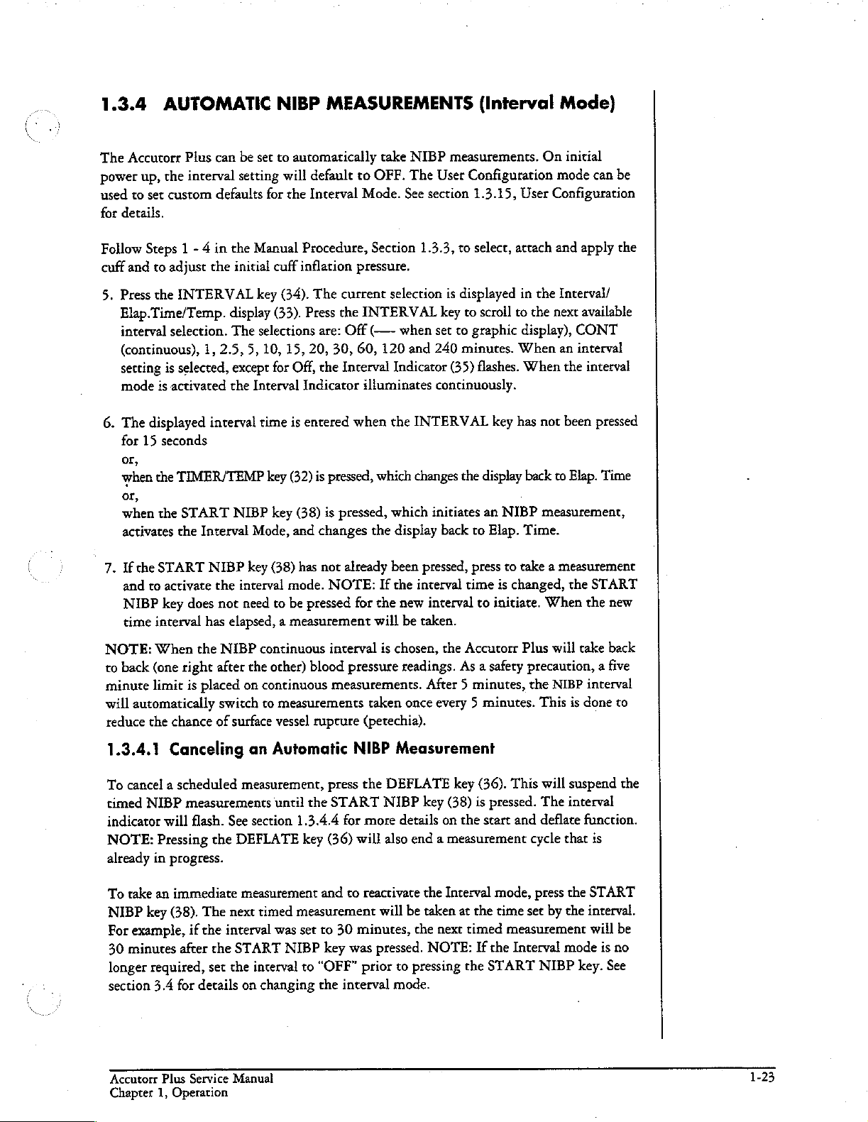
1.3.4
The
Accutorr
power
up, the
used
to
for
details.
AUTOMATIC
Plus
interval
set
custom
can
be
set
setting
defaults
NIBP
to
will
for
MEASUREMENTS
automatically
default
the
Interval
to
OFF.
Mode.
take
NIBP
The
See
(Interval
measurements.
User
Configuration
section
1.3.15,
Mode)
On
mode
User
Configuration
initial
can
be
Follow
cuff
5.
6.
Steps 1 - 4 in
and
to
adjust
Press
the
INTERVAL
Elap.Time/Temp.
interval
(continuous),
setting
mode
The
for
selection.
is
selected,
is
activated
displayed
15
seconds
or,
when
the
TIMER/TEMP
or,
when
the
START
activates
7. If
and
NIBP
time
NOTE:
to
back
minute
will
automatically
reduce
che
START
to
key
interval
When
(one
limit
the
the
activate
right
chance
the
Manual
the
initial
key
display
The
selections
1,
2.5,
5,
10,
except
the
Interval
interval
Interval
NIBP
the
does
has
the
after
is
placed
of
time
key
NIBP
Mode,
key
interval
not
need
elapsed, a measurement
NIBP
continuous
the
on
continuous
switch
to
surface
Procedure,
cuff
inflation
(34).
The
current
(33).
Press
the
are:
Off
15,
20,
30, 60,
for
Off,
the
Interval
Indicator
is
entered
(32)
is
pressed,
key
(38)
is
pressed,
and
changes
(38)
has
not
already
mode.
NOTE:
to
be
pressed
interval
other)
blood
measurements.
measurements
vessel
rupture
Section
pressure.
selection
INTERVAL
(—~-
when
120
Indicator
illuminates
when
the
which
which
the
display
been
If
the
for
the
new
will
be
is
chosen,
pressure
readings.
taken
(petechia).
1.3.3,
to
select,
is
displayed
key
to
scroll
set
to
graphic
and
240
minutes.
(35)
flashes.
continuously.
INTERVAL
changes
interval
once
the
display
initiates
back
to
pressed,
interval
taken.
After 5 minutes,
press
time
to
the
Accutorr
As a safety
every 5 minutes.
attach
and
in
the
Interval/
to
the
next
display),
When
an
When
key
has
not
back
to
an
NIBP
measurement,
Elap.
Time.
to
take a measurement
is
changed,
initiate.
When
Plus
will
precaution, a five
the
NIBP
This
apply
available
CONT
interval
the
interval
been
pressed
Elap.
Time
the
START
the
take
interval
is
done
the
new
back
to
1.3.4.1
To
timed
indicator
NOTE:
already
To
NIBP
For
30
longer
section
Accutorr
Chapter
Canceling
cancel a scheduled
NIBP
measurements
will
flash.
Pressing
in
progress.
take
an
immediate
key
(38).
example,
minutes
if
after
required,
3.4
for
Plus
Service
1,
Operation
measurement,
See
the
DEFLATE
measurement
The
next
the
interval
the
START
set
the
details
on
Manual
an
Automatic
until
section
interval
1.3.4.4
timed
measurement
was
NIBP
changing
the
key
set
to
press
START
for
(36)
and
to
to
30
key
“OFF”
the
interval
NIBP
Measurement
the
DEFLATE
NIBP
more
details
will
also
reactivate
will
minutes,
was
pressed.
prior
to
mode.
key
(36).
key
(38)
is
pressed.
on
the
start
end a measurement
the
Interval
be
taken
the
next
NOTE:
pressing
at
the
timed
If
the
mode,
time
measurement
the
START
This
will
The
and
deflate
cycle
press
set
by the
Interval
NIBP
suspend
interval
function.
that
is
the
START
interval.
will
mode
is
key.
See
the
be
no
1-23
Page 34

NOTE:
measurement
when
If
the
ready.
DEFLATE
can
be
key
taken.
(36)
The
is
START
pressed,
NIBP
it
will
INDICATOR
take
10
seconds
(39)
before
will
another
be
illuminated,
NOTE:
suspended
1.3.4.2
If
interval
minutes.
the
Accutorr
every
1.3.4.3
When
the
interval
time
interval
10
minutes.
(interval
Changing
Thirty
Plus
Effects
the
‘When
the
Room
the
same.
NOTE:
measurement
timed
interval
START
NIBP
in
the
Interval
indicator
time
is
changed
is
used
once
minutes
time
is
changed
will
take
of
Interval
Number
The
is
in
progress,
measurements
key
(38)
mode
flashes)
the
Interval
while
it
is
entered.
have
elapsed
to
10
minutes.
an
automatic
Changing
Setting
and/or
Bed
interval
is
setting
the
measurement
will
pressed.
not
and
the
until
the
Setting
the
Accutorr
For
since
NIBP
the
Room
Letter
can
activate
Room/Bed
NIBP
Start
Plus
example:
the
Once
measurement
last
timed
the
The
interval
Number
is
changed,
be
changed
will
stop
again
(interval
is
changed,
key
is
in
the
interval
automatic
time
in
10
and/or
the
interval
if
required.
and
the
indicator
the
is
pressed.
interval
time
measurement
is
entered,
minutes
Bed
setting
Also,
cuff
will
interval
mode,
the
is
set
to
60
the
and
then
Letter
will
ifan
NIBP
deflate.
flashes)
until
mode
new
and
once
on
remain
The
is
the
1.3.4.4
The
measurement
e@
INTERVAL
unscheduled
affect
taken
measurement
START
the
as
START
timing
if
measurement.
e@
INTERVAL
INDICATOR
NIBP
key
suspended
e@
INTERVAL
reset
with
elapsed.
and
NIBP
and
sequence.
mode
is
measurement
of
the
there
were
cycle - even
mode
is
(35)
flashes.
(38)
is
pressed.
and
the
cuff
mode
is
the
new
interval. A
DEFLATE
DEFLATE
active
interval
no
interruptions.
if
active
deflates.
active
Functions
functions
and
the
to
be
taken.
cycle,
the
unscheduled
and
the
No
additional
If a timed
and
the
measurement
have
START
therefore,
DEFLATE
NIBP
Taking
Only
one
measurement
measurements
measurement
interval
time
will
the
following
key
(38)
this
unscheduled
the
scheduled
measurement
key
(36)
is
is
in
progress,
is
changed.
be
taken
effects
is
pressed causing
measurement
measurements
is
taken
coincides
pressed.
will
after
The
be
taken
the
The
measurement
the
new
on the
timed
an
does
will
for
each
with
the
scheduled
INTERVAL
until
the
START
measurement
cycle
interval
time
not
still
be
is
is
has
1-24
Accutorr
Plus
Service
Chapter
Manual
1,
Operation
Page 35

1.3.5
The
MAP,
parameters
ALARMS
Accutorr
pulse
Plus
rate
and
equals
provides
SpOz.
or
falls
outside
“HI”
An
and
alarm
the
“LO”
alarm
violation
limits
occurs
that
limit
settings
when
have been
for
systolic,
one
or
more
specified.
diastolic,
patient
1.3.5.1
The
Factory
factory
See
alarms
SET
used
1.
default
section
can
ALARMS
to
set
Press
the
The
first
display
in
che
Interval/Elap.
display
top
lines
The
second
selected.
When
displayed.
low
alarm
Each
time
setting
LO,
Diastolic
LO,
SpO2
the
next
operation.
Setting
1.3.15,
be
alarm
which
graphics,
the
(all
Alarm
Default
is
86.
User
changed
key
(29)
values.
SET
ALARMS
time
this
shows
blink.
This
time
The
word
unit
has
When
is
selected.
the
SET
other
HI,
HI
and
press
of
for
the
the
Limits
all
parameter
The
User
Configuration
Configuration
as
required
and
the
Patient
key
(29)
key
is
pressed,
the
current
Time/Temp
the
symbol
indicates
SET
ALARMS
LO
is
displayed
been
configured
the
graphic
ALARMS
displays
Diastolic
SpO2
SET
blank).
LO,
LO.
When
ALARMS
alarms,
for
to
accommodate
Info.
(1
beep)
all
NIBP
high
systolic
display
3=5=
is
the
high
key
in
the
to
is
displayed,
key
(29)
The
order
MAP
all
of
key
except
mode
details.
Up
to
(33).
displayed.
alarm
(29)
Interval/Elap.
display
is
pressed a new
HI,
the
returns
Low
can
The
the
and
Down
enter
into
displays
alarm
When
When
is
selected.
is
pressed
graphics,
the
bottom
they
are
MAP
LO,
available
the
SpO,
be
used
to
factory
needs
Accutorr
and
of
Arrow
the
alarm
blank
except
value.
The
the
unit
the
graphic
the
Systolic
Time/Temp
the
symbol
lines
blink.
parameter
available
Pulse
Rate
parameters
is
OFF.
The
set
custom
custom
individual
keys
word
has
is:
Plus
defaults
patients.
(27 & 28)
set
mode.
for
the
HI
been
configured
is
displayed,
LO
parameter
display
====
This
is
selected
Systolic
HI,
and
have
been
to
normal
Low
SpO2
defaults.
for
The
are
systolic
is
displayed
the
(33).
is
indicates
HI,
Pulse
the
for
alarm
Systolic
Rate
selected,
to
is
2.
To
change
28).
the
alarm
To
cancel
DEFAULTS
If
the
Accutorr
NOTE:
settings
Accutorr
Chapter
The
Up
SET
Plus
If
for
Plus
1,
Operation
an
alarm
arrow
limit
setting.
all
of
the
key
ALARMS
returns
the
patient
che
Service
limit
increments
changed
(14)
(1
or
Arrow
to
size
new
patient
Manual
setting,
the
alarm
beep
tone).
keys
normal
is
changed,
size.
use
the
Patient
alarm
limit
values
while
have
not
operation
the
and
alarm
Info.
setting.
still in
been
pressed
saves
any
settings
Up & Down
The
Down
progress
alarm
for
will
of
15
limit
change
Arrow
arrow
decrements
changing,
seconds,
changes.
co
the
keys
press
the
default
Revised
(27
the
&
12/20/00
1-25
Page 36

Alarm
PARAMETER
Systolic
Adult
Pediatric
Neonate
Systolic
Aduit
Pediatric
Neonate
Diastolic
Adult
Pediatric
Neonate
Diastolic
Adult
Pediatric
Neonate
MAP
Adult
Pediatric
Neonate
MAP
Adult
Pediatric
Neonare
Pulse
Adult
Pediatric
Neonate
Pulse
Adult
Pediatric
Neonate
SpO2
Adult
Pediatric
Neonate
SpO2
Pediatric
Neonate
High
Low
Rate
Rate
High
Low
Adult
Limit
High
Low
High
Low
High
Low
Table
RANGE
Off,
60-260
Off,
60-160
Off,
50-125
Off,
55-150
Off,
55-130
Off,
45-115
Off,
40-200
Off,
40-150
Off,
35-100
Off,
30-120
Off,
30-50
Off,
25-50
Off,
90-200
Off,
90-150
Off,
60-110
Off,
40-100
Off,
40-70
Off,
30-70
Off,
100-245
Off,
100-245
Off,
100-245
Off,
35-120
Off,
35-150
Off,
75-200
Off,
61-99
Off,
61-99
OFf,61-99
60-95
60-95
60-95
UNITS
mmHg
mmHg
mmHg
mmHg
mmHg
mmHg
bpm
bpm
%SpO2
%SpO2
FACTORY
DEFAULT
Off
Off
Off
Off
Of
Of
Off
Of
Of
86
UNITS
OF
INCREMENT
5
5
5
5
5
5
5
5
1
1
1-26
1.3.5.2
An
range
e
The
e
The
with
«
The alarm
e
The
the
Alarm
alarm
condition
that
has
LEDs
for
parameter
Trend
tone
parameter(s)
recorder.
Violations
exists
been
set.
When
the
parameter
in
an
alarm
Screen).
is
sounded
chat
was
if
the
parameter
an
alarm
in
an
condition
(unless
in
an
alarm
limit
alarm
is
in
muted
condition
is
equal
to
is
violated,
condition
reverse
with
video
the
will
or
is
outside
the
following
flashes.
on the
MUTE
be
in
key
brackets
the
LCD
(Accutorr
(30)).
[ ]
Accutorr
high/low
actions
Plus
when
Plus
Service
Chapter
1,
limit
occur:
models
printed
Manual
Operation
on
Page 37

1.3.5.3
When
tone
ment
When
tone
value
SpO2
a
value
minutes
©
SpO2
MUTE
display
flashing. ® SpO2
Press
silence
parameter
key
How
an
NIBP
for 2 minutes.
has
been
an
SpO2
for
two
minutes.
changes
value
and
(30)
and
changes
that
is
outside
elapse.
is
measured
key
is
pressed. ¢ SpO2
flashes. + SpO2
hold
the
alarm
will
again.
to
Mute
alarm
exists,
The
taken
and
alarm
exists,
The
is
within
to a value
the
Example
at
89;
is
measured
the
MUTE
tone.
continue
Alarms
press
the
MUTE
alarm
tone
will
is
within
alarm
set
(within 2 minutes): ¢ SpO2
the
is
measured
key
The
to
flash.
the
press
the
tone
the
alarm
that
is
alarm
limit,
alarm
is
measured
ar
at
89; the
(30)
(2
MUTE
LED
To reactivate
alarm
MUTE
will
limits.
within
tone
91;
beep
key
return
limits.
key
return
If
the
the
alarm
sounds
at
88;
no
alarm
alarm
tone
tones,
(31)
illuminated.
(30)
(1
beep
after
two
minutes,
(30)
(1
beep
after
two
minutes,
during
the
that
two
acceptable
tone
and
there
tone
sounds
approx. 3 seconds)
alarm
low
the
is
range,
will
return
alarm
SpO2
no
alarm
sounds
and
The
tone
function,
tone)
to
unless a new
tone)
to
unless
minutes
and
before
limit
has
display
tone,
and
the
the
SpOz
to
LEDs
for
silence
silence
then
flashes. e The
permanently
press
the
measure-
the
the
SpOz
the
measured
returns
the
two
been
set
but
the
display
display
the
alarming
the
alarm
to
SpO2
stops
flashes.
MUTE
alarm
to
90.
1.3.5.4
‘When
changing
displayed
detected,
1.3.15
The
sizes,
for
table
and
Measurement
1
2
3
4
5
6
Alarms
is a different
the
information
below
the
Order
and
the
rooms
alarm
settings
describes 6 measurements
effect
on
Room
lia
1
2/a
dla
dla
Va
Changing
and
patient
change
on
custom
the
alarm
/Bed
beds,
the
size
than
to
defaults.
settings.
Adult
Adult
Pediatric
Adult
Adult
Adult
the
Room
alarm
the
original
the
defaults
in
Patient
Size
Number
settings
room/bed.
for
the
different
rooms/beds
and/or
will
change
When a new
different
Alarm
Settings
Have
been
Remain
Changed
pediatric
Changed
size
patient.
Remain
Remain
settings
ist
measurement
they
need
manually.
Bed
if
the
patient
and
different
manually
the
same.
to
defaults
size
patient.
to
defaults
the
same.
the
same.
that
were
to
be
Letter
final
patient
size.
See
set.
for
for
If
the
set
from
are
required,
set
again
room/bed
size
is
section
patient
a
an
adult
alarm
the
NOTE:
and
PRECAUTION:
size
Accutorr
Chapter
the
and
The
patient
alarm
Plus
1,
Operation
alarm
settings
size
is
It
settings
Service
the
is
the
users
are
as
Manual
can
be
changed,
same.
responsibility,
required,
if
necessary,
when
changing
when
the
roomlbed,
changing
to
the
room/bed
assure
the
patient
1-27
Page 38

1.3.6
All
data.
in
memory.
two
measurement.
separate
information
When
flash.
(20)
manually
automatically
NOTE:
The
stored
measurements
patient
TO
models
Each
minutes
entry.
80
entries
When
will
illuminate
for
The
Accutorr
data.
(indicated
of
the
time a successful
When a temperature
after
is
100
any
unit
The
VIEW
If a temperature
When
available,
are
entries
patient;
delete
Plus
Accutorr
at a time.
AND
Accutorr
an
will
NIBP
by
Plus
NIBP
measurement,
either
then
stored
into
are
continuously.
or
the
oldest
also
automatically
uses
Plus
The
the
room
NIBP
NIBP
the
stored
when
stored
DELETE
are
capable
measurement
measurement
measurement
or
temperature
SpO2
data
trend
memory,
into
trend
Once
100
new
data
data
for
the
delete
the
Systolic,
models
number/bed
with
data
that
STORED
of
storing
is
made,
is
made
it is
stored
is
made
measurements
is
also
stored.
the
MEMORY
memory,
entries
is
available,
currently
data
Diastolic,
Trend
Screen
is
viewed
letter).
DATA
up
to
100
the
data
between
as
the
sare
outside
are
displayed
that
MAP,
the
MEMORY
stored,
the
Accutorr
is
24
and
use
is
for
this
the
(Trend
entries
is
automatically
two
minutes
entry
time,
are
stored
FULL
old
data
patient.
hours
old.
Temp
the
LCD
currently
Mode)
of
measurement
before and
with
the
it
is
stored
and
Indicator
FULL
Indicator
can
be
Plus
will
displays
to
display
selected
stored
NIBP
as
a
SpO2
(20)
will
deleted
to
view
up
to
5
1.3.6.1
1.
Press
illuminates.
2.
Press
current
Rate
3.
To
To
che
the
and
Consecutive
allow
the
wrap, a double
for
the
NIBP
Time/Temp
key
(32).
exit
View
DATA
Patient
patient.
the
The
Temp
displays.
presses
stored
measurements
beep
measurement
display
view
the
Stored
SCAN
Info.
stored
or
tone
(33).
stored
Measurements
key
(22)
Up
and
Down
data
is
pressing
data
will
that
To
view
mode,
and
to
sound.
(1
beep
tone).
Arrow
displayed
holding
continuously
is
displayed,
the
press
keys
in
the
If a temperature
time
of
the
DATA
on
the
Accutorr
The
DATA
(27 & 28)
the
Systolic,
UP
wrap
around.
then
- - - -
measurements,
SCAN
to
or
DOWN
measurement
is
shown
SCAN
key
Plus
NIBP
Indicator
view
stored
Diastolic,
When
press the
arrow
the
in
(22)
MAP,
will
measurements
is
not
the
(1
(23)
data
for
the
Pulse
available
Interval/Elap.
TIME/TEMP
beep).
1-28
Revised
12/20/00
Accutorr
Plus
Service
Chapter
Manual
1,
Operation
Page 39

1.3.6.2
The
stored
LCD.
Up
time
order,
display
one
1.
on
arrow
To
view
Date
To
View
the
Screen
measurements
to 5 stored
with
the
displays,
and
measurements
the
newest
side
of
the
more
more
measurements
Time,
20/05
20/05 02:58
Stored
the
LCD
measurements
Measurements
Accutorr
on
the
Accutorr
are
measurement
when
more
press
VW.
03:00
S/D/M
114/64
123/61
Plus
NIBP
Plus
models
displayed
are
the
at
at
the
top. A scroll
measurements
only
available
LCD
Up
83
84
on
the
with
with
one
time.
or
e
61
60
Accutorr
Trend
are
in
Down
Screen
Trend
Measurements
bar
with
available
the
direction
Arrow
°FIC
98.7
985
Plus
NIBP
and
Screen
are
displayed
are
one
or
both
to
view.
of
the
key
(9 & 10).
%SPO2
96
=
97
with
Trend
SpO2
displayed
arrows
When
only
arrow.
Scroll
in
the
in
will
Figure
1-10 - LCD
1.3.6.3
While
stored
1.
Select a room/bed
details
2.
DATA
scan
the
Plus
2.
On
DATA
To
viewing
measurements
on
When
SCAN
through
Accutorr
will
the
Accutorr
SCAN
a
20/05
Trend
Delete
selecting a room/bed.)
you
scan
the
stored
for
where
are
uncertain
key
all
of
Plus
is
through
Plus
key
i
02:30
List
Display
Stored
data,
you
the
currently
stored
(22)
(2
the
rooms/beds
scanning,
the
NIBP
(22)
(1
Measurements
can
what
beep
press
rooms/bed
only,
beep
185/105
129/62
delete
information
If
rooms/beds
tones,
when
tone).
184
the
displayed
it
is
the
more
that
have
the
DATA
with
the
The
ES
135
|
Alarm
most
patient.
can
currently
have
than 3 seconds).
data
stored
desired
DATA
59
Violated
on
all
recent
be
deleted.
stored
stored.
SCAN
data
room/bed
SCAN
ーー
98.2
Models
measurement
displayed
data,
To
key
only
Indicator
97+
Measurement
of
the
(See
section
room/bed,
press
and
The
Accutorr
stop
on a Room/Bed
(22).
NOTE:
once.
is
displayed,
(23)
Accutorr
or
all
of
the
1.3.2.3
hold
illuminates.
go
Plus
The
press
for
to
step
the
will
Accutorr
Plus
as
the
3.
When
key
(21)
4.
When
key
current
5.
On
the
exit
NOTE:
NOTE:
(21)
while
Accutorr
Chapter
the
(1
viewing
(21)
(2
patient.
Accutorr
che
delete
The
To
delete
powering
Plus
1,
Operation
most
beep
any
beep
data
unit
will also
al!
Service
recent
stored
tone,
approx. 3 seconds)
of
the
stored
tones,
approx. 6 seconds)
When
all
dara
Plus
NIBP
mode.
automatically
information
on
the
unit.
Manual
data
is
displayed,
measurements,
is
cleared
only, press
delete
for
all
patients,
to
to
the
the
press
delete
press
delete
patient
DATA
data
that
press
and
hold
this
measurement.
and
hold
all
stored
size
will
SCAN
is
and
key
24
hours
hold
the
DELETE
the
DELETE
measurements
be
the
default
(22)
(1
beep
old.
the
DELETE
INFO.
INFO.
for
the
selection.
tone)
to
INFO.
key
1-29
Page 40

1.3.7
The
LCD
List
as
described
the
alarm
Down
Arrow
User
Configuration
beep
volume.
1.
Press
the
alarm
indicates
2.
Press
the
the
alarm
3.
Press
the
4.
Press
the
the
SpO2
5.
Press
the
SETTING
on
the
Accurorr
in
volume
volume
and
keys
(9 & 10),
See
section
MENU
is
this
item
LCD
Up
volume.
SELECT
LCD
Up
volume.
MENU
THE
Plus
section
mode
initially
the
key
can
and
The
key
and
The
key
1.3.6.
SpO2
and
can
1.3.15,
(8)
to
highlighted
be
Down
selections
(11)
Down
selections
(8)
again
ALARM
models
It
is
beep
volume.
the
SELECT
be
used
User
display
changed.
Arrow
are:
to
move
Arrow
are:
to
exit
VOLUME
with
Trend
also
used
to
display a menu
The
MENU
key
(12)
to
set
custom
Configuration
the
menu.
The
when
the
menu
keys
(9 & 10)
OFF,
1,
2,
the
highlighting
keys
(9 & 10)
OFF,
1,
2, 3,
the
menu
AND
Screen
is
used
key
are
used
defaults
for
3, 4,
and
for
details.
menu
is
shown
is
displayed.
to
change
and 5 with 5 being
to
SpO2
to
change
4,
and 5 with 5 being
return
BEEP
to
display
which
(8),
the
to
set
the
alarm
*
the
current
beep
the
current
to
the
VOLUME
the
is
used
LCD
Up
these
volumes.
volume
in
figure
The
highlighting
selection
the
volume.
selection
the
Trend
screen.
Trend
to set
and
The
and
3-4.
The
loudest.
loudest.
for
for
NOTE:
the
unit
Alarm
SpO2
Volume
Figure
Any
is
Volume
Beep
1-11
changes
turned
Menu
off
made
and
‘
to
then
the
back
alarm
on
again.
3
volume
or
the
SpO2
volume
will
be
erased
when
1-30
Accutorr
Plus
Service
Chapter
Manual
1,
Operation
Page 41
1.3.8
The
LCD
viewing.
to
adjust
1.
Press
generated
second
2.
To
quickly
key
(9
Arrow
3.
The
LCD
not
pressing
SETTING
on
the
Accutorr
The
MENU
the
contrast.
and
hold
when
beep
tone
adjust
or
10).
For
key.
contrast
either
THE
key
the
MENU
the
key
is
generated,
the
contrast,
fine
adjustment,
adjustment
the
LCD
Plus
(8)
and
is
first
LCD
CONTRAST
models
the
key
(8)
pressed
release
press
is
saved
UP
or
with
Trend
LCD
Up
and
(2
beep
tones,
and
the
the
key.
and
hold
momentarily
by
either
Down
Arrow
(View
Screen
Down
approx. 3 seconds). A beep
display
either
press
pressing
keys
Angle
can
be
Arrow
changes
the
LCD
either
the
(9 & 10)
adjusted
keys
(9 & 10)
to
the
Up
or
the
LCD
MENU
for
15
Adjustment)
Down
key
seconds.
for
optimum
menu.
Up
or
(8)
are
used
tone
When
Arrow
Down
again
is
a
or
NOTE:
readjusted
The
by
contrast
the
setting
user.
will
be
the
same
each
rime
the
unit
is
turned
on,
unless
Accutorr
Chapter
Plus
Service
1,
Operation
Manual
1-31
Page 42

1.3.9
DISPLAY
TIME
OUT
MODE
To conserve
time
between 5 and
DC
source,
power
time
To
turn
any
key.
power,
out can
the
source.
out
minutes.
on
the
be
most
set
berween 3 and
60
minutes.
user
configuration
See
User
LCD
light,
displays
Configuration,
Since
press
will
15
the
allows
the
MENU
blank
at
user
minutes.
Accutorr
the
setting
section
key
selected
The
LED
Plus
can
1.3.15
(8).
display
be
of
separate
for
more
To
turn
times.
The
time
powered
times
information
on
the
LCD
out can
from
for
LED
illumination
be
set
either
an
AC
each
type
of
on
setting
displays,
press
or
che
1-32
Accutorr
Chapter
Plus
Service
1,
Operation
Manual
Page 43
1.3.10
To
obtain
See
Section
section
3.10.2;
SpO2
SpOz
measurements
3.10.1
for
MEASUREMENTS
and
SpOz
for
units
with
Datascope
units
with
Masimo
(Accutorr
Heart
Rate
SpO2;
SpO2
see
from
the
for
units
section
Plus
model
Accutorr
with
1.3.10.3)
Plus
mode!
Nellcor
with
with
SpO2
SpO2)
SpO2:
see
CAUTION:
cuff
in
place.
CAUTION:
CAUTION:
patient
deoxygenation
completely
CAUTION:
NOTE:
check
understand
In
the
patients
e
Ifyour
different
e
Check
e
İn
electrosurgery,
e
Check
needed.
1.3.10.1
A.
Introduction
Do
not
place
A
pulse
oximeter
A
pulse
oximeter
is
indicated,
the
Ensure
proper
the
event
you
vital
patient
chat
to
finger
the
make
Nail
polish
is
or
sensor
sure
Datascope
the
sensor
should
should
blood
patients
signs
poorly
routing
are
unable
by
perfused,
toe).
is
properly
make
sure
che
site
and
condition.
fungus
Pulse
on
an
extremity with
not
be
used
be
considered
samples
of
the
patient
to
obtain a reading,
alternate
area
means
try
aligned.
the
sensor
is
clean / non-greasy. Clean
should
Oximeiry
as
an
apeana
an
early
should
be
analyzed
cable
to
avoid
and
applying
is
not
too
be
removed.
Sensors
an
invasive
mnitor.
warning
by a laboratory
entanglement
or
the
consider
the
sensor
close
the
to
catheter
device.
reading
As a trend
andlor
is
following:
to
another
ESU
devices
the
site
or
blood
pressure
towards
co-oximeter
strangulation
inaccurate,
site
(i.e.
A
or
cables.
and
sensor
to
if
A
wide
range
model
with
SpOz.
patients
The
The
long-term
FLEXISENSOR“
The
are
GUARD™
GUARD™
Use
contact
The
diode
patient’s
blood
ranging
DATASENSOR
FLEXISENSOR®
monitoring
ear
sensor
available
for
(used
(used
of
the
sensors
or
transfer
sensor
is
(detector).
extremity
or
tissue
of
Datascope
The
sensors
from
infants
is
intended
SD,
for
SD
is
used
is
intended
use
with
for
large
for
infants).
does
not
of
excessive
composed
The
emitter
(finger,
components.
sensors
cover
to
large
for
available
large
adults,
when
for
long-term
the
FLEXISENSOR®
adults,
cause
any
heat
of a dual
light
discharges
toe,
ear).
The
Accutorr
are
available
both
short-term
adults.
short-term
in
five
adult
the
DATASENSOR
adult
adults
and
penetration
to
the
patient.
emitting
two
The
detector
Plus
for
connection
and
long-term
adult
monitoring.
different
ear,
monitoring. A range
colors
sizes,
provides
adults,
SDs.
pediatrics),
diode
model
pediatrics,
is
not
They
are
and
of
the
skin,
(LED)
(wave
receives
with
available
lengths)
the
convenient
Coban
nor
(emitter) and a photo
SpO2
to
the
of
is
of
light
then
Accutorr
monitoring
both
short-term
and
infants.
or
suitable.
disposable
in
2styles,
with
SENSOR
there any
light
not
electrical
into
absorbed
uses
the
Plus
needs
and
The
bandages
SENSOR
the
by
the
on
Accutorr
Chapter
Plus
Service
Operation
1,
;
Manual
Revised
02/15/00
1-33
Page 44

relative
saturation)
The
absorption
and
Pulse
key
benefits
eElectro-Surgical
DATASENSOR
absence
design
prevents
ing
with
e
Monitoring
1.
2.
3.
e
Tracking
perfusion
Plus
model
poor
peripheral
of
of
false
alarms
unit
operation.
Restless
The
sensor
the
sensor
Light
emitting
When
in
increasing
reducing
reduces
of
due
with
the
Weak
to
of
the
two
light
wavelengths
Rate
measurements.
the
sensors
Noise
and
che
electro-surgical
design
to
the
the
presence
it
to a maximum
it
during
number
Peripheral
hypothermia,
SpO2
perfusion.
are:
(ESU)
FLEXISENSOR®
during
Patients - Motion
used
patient.
diodes
of
is
designed
Rejection - The
the
use
noise
with
(LEDs)
of
motion,
quiet
periods
monitoring
Pulse
hypovolemia,
to
to
compute
SD
provide
of
ESU
(ESU
can
entering
their
and
of 15
Levels - Many
automatically
the
monitor,
artifact
detectors
to
interruptions
rejection
recommended
gather a strong
the
software
seconds
during
obtain a fast
reduced
increase
and display
sensor
be
and
configuration
uninterrupted
set
at
any
via
is
achieved
bandages
adjusts
patients
cardiac
the
motion,
response.
false
alarms
suffer
output,
its
gain
SpO2
(functional
of
both
monitoring
power
level).
the
sensor,
in
several
assures a snug
signal
from
“averaging-period”,
and
automatically
This
combination
from
patient
poor
peripheral
etc.
to
track
and
This
and
interfer-
ways.
fit
the
patient.
motion.
The
Accutorr
patients
with
the
of
#
Rejection
ambient
Accutorr
rejection
levels
of
in
keep
Patient
bandage
and
B.
Sensor
Selection
monitoring
Sensor
are
provided
placement
light,
of
ambient
high
levels
the
composition
out
Comfort - The
safely
of a specific
Selection
ensure
Cable
of
Ambient
i.e..,
operating
Plus
model
with
of
ambient
of
ambient
of
two
to
the
Selection
duration.
in
each
on
Top
light.
light.
ambient
of
light.
styles
particular
and
sensor
General
Table,
sensor
that
page
cable
Light - Many
room
SpO2,
the
The
monitor
The
enclosed
light
on
adults
the
bandages, which
FLEXISENSOR
(SENSOR
GUARD
patient’s
Application
is
based
on
guidelines
3-25.
Instructions
package.
side
is
placed
monitoring
lights,
neonatal
sensors,
automatically
design
of
the
with
are
SD
TM
anatomy.
the
patient’s
for
the
For
optimal
in
the
situations
phototherapy,
and
the
bandages
DATASENSOR
sensor
operation.
used
with
line
is
and
Coban)
size,
selection
for
the
DATASENSOR
correct
involve
each
measures
the
designed
physical
of a sensor
application
position.
and
prohibits
The
FLEXISENSOR®
to
work
which
condition,
of a sensor
and
See
Cable
on
Bottom
high
levels
heat
warmers,
contribute
corrects
opaque
conform
are
FLEXISENSOR®
figures
to
the
for
the
interference
material
SD,
with a disposable
comfortably
and
expected
provided
to a patient
below.
of
etc.
The
high
used
helps
in
the
1-34
Figure
1-12
Datasensor
Durasensor
Placement
Revised
02/15/00
or
Figure
1-13
Flexisensor”
Placement
Accutorr
Service
Plus
Chapter
Manual
1,
Operation
Page 45

C.
Sensor
1.
Align
the
2.
Push
connector
3.
The
Rate
4.
If
desired,
Beep
D.
Sensor
Before
Do
not
For
long
e
Do
not
sensors
Plus
see
Section
Connection
the
cable
Accutorr
che
digital
LED's.
Volume,
use,
use
rolling
Plus
cable
is
securely
SpO2
adjust
Inspection
always
the
sensor,
sensor
drop
on
in
the
accessory
stand
5.2,
to
connector
model
connector
in
place.
values
the
beep
for
details
inspect
life:
the
sensors,
cable
floor,
pouch,
using
the
“Optional
the
Accutorr
on
the
sensor
with
5002.
into
the
SpO2
and
SpO2
pulse
volume.
on
or
connector
or
give
optional
Accessories”.
See
adjusting
cables,
other
or
coil
cable
Plus
assembly
Connector
rate
section
the
and
connectors
if
damaged.
sharp
the
sensor
retainer.
model
will
3.7,
beep
volume.
shocks
cable
with
with
the
(15).
Confirm
be
displayed
Setting
for
damage,
Replace
to
the
sensor(s).
and
store
For
accessory
SpO2
SpO2
Connector
that
in
the
the
Alarm
i.e.,
cuts
with a good
Between
on
the
side
part
number
(15)
the
cable
$pO2
and
Volume
and
abrasions.
working
use,
of
the
information
on
pulse
and
sensor.
store
the
Accutorr
e
Avoid
running
@
Avoid
strong
e
Watch
e
Watch
E.
For
e
@
for
for
Sensor
the
BEST
DO
NOT
pressure
extremity
FLEXISENSOR®
opposite
Encourage
is
not
possible & the
FLEXISENSOR®
Check
the
every 8 hours
circulation
necessary,
immediately
more
frequently
any
cart,
pulls
on
the
cracks
in
the
cracks,
cuts,
Performance
performance:
PLACE
cuff
may
the
the
DATASENSOR
impairment.
remove
any
in
place.
obstruct
SD
is
site
of
the
patient
SD
for
indications
and
remove
on
infant
sensor
Placement
to
to
reapply
the
bed,
or
any
sensor
cable
DATASENSOR
rips,
fogging,
on
an
of
normal
arterial
remain
placed
catheter
still.
patient
assure
good
site
of
skin
Check
the
sensor
and
active
blood
on
to
every 2 hours
the
sensor.
and
piece
of
equipment
(10
1bs/4kg).
housing.
or
signs
extremity
an
arterial
flow. False
that
same
or
blood
Patient
abrasions,
motion
remain
adhesion,
sensor
site
If
any
find
an
alternate
patients.
over
of
moisture
with
an
arterial
catheter
extremity.
still,
or
and
sensor
every 4 hours
of
or
pulse
rate
Place
pressure
may
affect
replace
change
the
the
check
the
displacement,
above
site.
the
sensor
in
the
FLEXISENSOR®
catheter
blood
pressure
information
the
sensor
cuff.
the
sensor's
the
sensor
site
of
the
FLEXISENSOR®
sensor
if
the
ear
mentioned
NOTE:
Check
cable.
or
blood
cuff
on
an
may
result
if
on
the
limb
performance.
bandage
DATASENSOR.
damage,
clip
indications
is
the
on
SD
or
used.
occur,
sensor
SD
the
If
the
site
If
site
it
Accutorr
Chapter
Plus
Service
1,
Operation
Manual
Revised
02/15/00
1-35
Page 46

e
Incorrect
performance.
not
acquisition
e
Use
monitoring
2-4
bandage.
©
Do
affect
also
e
Sensor
situations:
Electro-cautery
Motion
during
monitoring
Weak
pulses
placement
be
placed
of a reliable
of
the
DATASENSOR
situations
hours
to a different
not
over-tighten
SpO2
result
in
configuration
Artifact - The
motion
Peripheral
on
patients
can
also
reduce
Select
an
alternate
on
the
patient's
signal.
exceeding
site
the
sensor
readings
pressure
interruptions
and
necrosis
provides
Noise - Electro-cautery
monitor’s
and
reducing
Pulses - The
with
site
finger
is
not
(finger/toe)
bandages.
may
reduce
and
virtually
it
and
false
decreased
the
acquired
(toe)
or
use a FLEXISENSOR®
correctly
recommended
4-6
hours,
either
or
use a FLEXISENSOR®
Excessive
readings
other
skin
uninterrupted
noise
software
during
alarms.
monitor's
peripheral
adjusts
inactivity.
gain
sensor
signal,
or
if
the
fingernails
for
long-term
reposition
pressure
below
true
damage.
monitoring
rejection
is
perfusion.
is
the
“averaging
This
decreases
automatically
and
therefore
interfere
monitoring
the
DATASENSOR
SD
on
the
monitoring
SpOz.
Excessive
during
designed
period”
the
increased
compromise
SD
if
the
(4-6
with
its
following
into the
increasing
number
sensor
can
with
the
hours).
appropriate
site
pressure
sensors.
to
For
every
can
can
it
of
track
Datascope
Sensors
Approximate
Patient
Where
Long
Term
toring
Electro-Surgical | Included
Interference
Suppression
(ESIS)
Reusable
Bandage
Part
493
*
<Non-adbesive
**
See
**%*
Additional
(3°
SpO2
Sensor
Large
Adult (LA)|(A)
>80kg/
Weight
Used
or
Short
Moni-
Type | Adhesive, | Adhesive, | Adhesive,
|Sensors | 0998-00-0
Bandages|
Accessories,
sensor
|>1761bs
Fingers,
Toes
Long
Short Short
Term Term
Yes
20
Disposable | Disposable | Disposable | Adhesive*
076-06
0683-00-0 | 0683-00- | 0683-00- | 0683-00- | N/A
409-01
bandages
ave
Chapter
choices:
cable
plus
Selection
Adult
0 - 90kg/
166-198
Ibs
Fingers,
Toes Toes
&
Long
¡Included
Up
to
|Yes
Up
Uses
recommended
0060-00-0026-02
7°
|20Uses
|0998-00- | 0998-00- | 0998-00- | 0998-00- | 0600-00-0026-01
0076-05
0409-02
for
premature
5,
for
more
detailed
extension
cable).
&
Table
Pediatric | Infant
(P)
|10-
|40kg/
22-88
Ibs
|Fingers,
|Long&
Short Short
Term
[Included
to | Yes
|to
20
Uses Uses
(0076-04 (0074-03 | 0074-05
|0409-03
infants
information.
(10'
sensor
0)
45-
10kg/
|10-22
Ibs
|Feet,
Palms,
Big
|Long&
Term
¡Included | Included | Included
Up
|YesUp
to
20
|Non- . |
[0415
to
minimize
prenatal
cable),
Adult
Ear
(AE)
>40kg/
>88
jbs
Adult
Ear
Toes
|Long&
Short
Term
|YesUp | Yes
to
20
Uses
Adhesive | Disposable
shin
damage.
0020-00-0071-01
Datasensor
|40+
|90+
Fingers,
|Short
6-Months
_|(3’
N/A
kg/
jbs
Toes
Term
sensor
cable)***
1-36
Revised
02/15/00
Accutorr
Service
Plus
Chapter
Manual
1,
Operation
Page 47

1.3.10.2
*
This
1.Select
2.
Plug
SC10
catheter
CAUTION:
CAUTION:
Sequence
feature
applicable
the
the
extension
or
for
only
if
available
appropriate
sensor
directly
cable.
blood
pressure
When
equipped
including
oxygen
transducers
Tissue
damage
application
Sailing
to
Carefully
instructions,
establishing
or
installed
sensor
for
into
the
NOTE:
cuff
with
Nellcor®
or
or
use,
inspect
the
read
the
and
SpO2
on
your
the
patient
SpO2
Do
not
place
in
place.
Nellcor®
Oxisensor™
may
cause
inaccurate
such
as
sensor
site
sensor
directions
all
precautionary
with
Nellcor®
unit.
from
Page
connector
improper
measurements
wrapping
periodically,
(15)
the
sensor
Sp02,
use
patient
dedicated
oximeter
it
too
for
use,
information
3-28
or
if
necessary,
on
an
extremity
only
Nellcor®
adbesive
performance.
may
be
caused
tightly,
applying
or
failing
the
Accutorr
before
Pulse
Oximetry*
oxygen
sensors.
by
to
position
Plus
use.
use a Nellcor®
with
an
invasive
transducers
Use
of
other
incorrect sensor
supplemental
it
appropriately.
operating
tape,
CAUTION:
CAUTION:
CAUTION:
CAUTION:
3.
The
digital
Rate
LED’s.
Excessive
with
Inaccurate
significant
methemoglobin);
exposure
Xenon
or
interference;
cuff,
In
patients
result.
and
interventation.
If
immediately.
solution.
SpO2
ambient
opaque
readings
levels
to
excessive
light
direct
sunlight;
arterial
certain
situations
with
Verification
patients
the
sensor
DO
value
and
materials.
source),
and
catheter,
thick
with
or
To
NOT
light
may
cause
may
be
caused
of
dysfunctional
or
intra-vascular
illumination,
bilirubin
excessive
placement
chronic
patient
prevent
patient
of a sensor
or
intra-vascular
in
which
or
pigmented
of
oxygenation
lung
cable
is
damage
ATTEMPT
SpO2
Pulse
inaccurate
by
incorrect
hemoglobins,
dyes
such
such
as
lamps,
florescent
movement;
on
perfusion
disease,
damaged
Rate
and
skin,
inaccurately
should
before
do not
TO
STERILIZE.
will
measurements.
sensor
(i.e.
carbobemoglobins
as
indocyanine
surgical
an
line.
be
in
soak
be
lamps
lights,
venous
pulsations;
extremity
signal
strength
low
made,
especially
instituting
any
way,
or
immerse
displayed
Cover
application
infrared
that
SpO2
discontinue
on
or
green
methylene
(especially
heating
electro-surgical
has a blood
are
low,
readings
in
preterm
any
therapy
use
the
sensor
che
$pO2
the
sensor
use;
or
ones
lamps,
pressure
such
will
or
in
any
and
blue;
with
à
as
in
infants
liquid
Pulse
4,
If
desired,
Beep
Accutorr
Chapter
adjust
Volume”,
Plus
Service
1,
Operation
the
for
details
Manual
beep
volume.
on
adjusting
See
Section
the
3.7,
beep
“Setting
volume.
the
Alarm
Volume
and
Revised
02/15/00
1-37
Page 48

1.3.10.2.1
NELLCOR®
Sensors
NELLCOR®
and
patients.
OXISENSOR™
mounted
oxygen
The
DURASENSOR
its
optical
oxygen
NOTE:
of
NELLCOR®
NELLCOR
A.
Selecting a Sensor
Sensors
the
appropriate
which
sensor
tion
of
B.
Cleaning
provides a family
Specific
oxygen
on
adhesive
transducer
components
transducer
NELLCOR® * OXIBAND
Incorporated.
Incorporated.
are
designed
sensor,
sites
monitoring.
and
sensors
transducers
tape.
system
is
are
are
®
DS-100A
mounted
an
adhesive
for
specific
consider
available,
Re-Use
of
sensors
have
been
are
OXIBAND®
reusable
adult
in a plastic
sensor
OXISENSOR™
sites
the
patient’s
whether
suitable
developed
sterile
oxygen
sensors
digit
oxygen
casing.
for
application
and
DURASENSOR®
on
patients
weight,
sterility
for a wide
for
neonates,
adhesive
transducers
that
are
applied
transducer
The
NELLCOR®
to
and
DURAFORM™
with
designated
level
is
required,
variety
infants,
sensors
and
with
forehead
are
of
activity,
and
of
clinical
children,
with
optical
the
DURAFORM™
disposable
is a reusable
RS-10
or
registered
weight
adequacy
the
reflectance
temple.
trademarks
are
trademarks
ranges.
of
anticipated
settings
and
adults.
components
adhesive.
sensor
with
of
To
select
perfusion,
dura-
Do
not
immerse
oxygen
adhesive
DURAFORM™
wiping
ethylene
each
C.
To
observe
If
do
surgical
lights,
performance,
OXISENSOR™
measurements
internal
relatively
transducer,
in
water
with a disinfectant
oxide.
patient.
Performance
insure
optimal
all
warnings
excessive
so
reflectance
ambient
may
result
lights,
infrared
carotid,
poor.
oxygen
any
ORISENSOR™,
the
NELLCOR™
or
cleaning
oxygen
Use a new
Do
not
transducers,
re-sterilize
Considerations
performance,
and
cautions.
light
is
in
inaccurate
especially
heating
and
from
For
lamps,
the
patient
R-15
adult
the
nasal
this
sensor
low
peripheral
transducer,
DURASENSOR®,
RS-10
solution.
and
such
as
70%
OXIBAN
present,
measurements.
those
nasal
may
D®
OXISENSOR™
use
an
cover
with a xenon
and
direct
weighs
septal
more
oxygen
anterior
obtain
perfusion,
which
is
oxygen
Clean
DURASENSOR®,
the
NELLCOR®
alcohol.
adhesive
appropriate
measurements
applied
Do
wrap
oxygen
the
sensor
Light
sources
light
source,
sunlight.
than
50 kg
transducer.
ethmoid
consider
to
the
OXIBAND®
transducer,
not
or
sensor,
site
with
that
If
poor
(110
Because
artery,
when
using
forehead
or
RS-10 oxygen
sterilize
FORM-A
transducers.
apply
opaque
can
affect
bilirubin
perfusion
lbs.),
the
an
peripheral
the
NELLCOR®
ος
any
NELLCOR®
OXIBAND®
by
irradiation,
adhesive
it
as
directed,
material.
performance
lamps,
affects
consider
R-15
artery
supplied
or
temple.
DURAFORM™
„and
transducer
steam,
bandage
and
Failure
include
fluorescent
instrument
using
the
obtains
perfusion
its
by
is
RS-10
by
or
for
co
the
1-38
Revised
02/15/00
Accutorr
Service
Plus
Chapter
Manual
1,
Operation
Page 49

If
patient
e
Verify
e
Use a new
e
Move
e
Use a type
D-25,
NELLCORO
SELECTION
GUIDE
Patient
Size
Duration | Short
of
Sterility | Sterile!
Patient | Limited
Activity, | Activity
Use
movement
that
the
sensor
sensor
the
sensor
of
sensor
D-20,
N-25,
SENSOR
|D25/D25L — [R-15
Adult
|>30kg
or
Term
OXISENSOR | OXISENSOR | OXISENSOR | OXISENSOR | OXISENSOR | RS-10
adult
digit
oxygen
transducer
presents a problem:
is
properly
with
fresh
adhesive
to a less
FAMILY
Long | Short
active
that
tolerates
or
120
oxygen
Adult
>50
kg
or
Long
Term
Sterile?
Inactive
[adult
nasal | neonatal
oxygen
|transducer
site.
and
securely
backing.
some
transducer.
N-25
Neonatal
<3
kg
>40
Short
|Long
Sterile! Sterile? Sterile!
Limited
Activity
oxygen
{transducer
patient
kg
or
Term
_|
applied.
motion,
+20
Infant
1-20
Short
[Long
Limited
Activity
infant
oxygen
transducer transducer
such
as
the
D-20
Pediatric
kg
or
Term
digit | pediatric
10-50
Short
{Long
Limited
Activity
digit
Term
oxygen
OXISENSORTM
RS-10
Adult
kg
or
>40
Short
Non-
sterile
Limited
Activity
reflectance
|oxygen
__|
transducer
kg
Term
"In
an
unopened,
undamaged,
All
NELLCOR™
25495
Whirehall
1-800-NELLCOR.
D.
Automatic
The
oximetry
automatically
whenever a new
adjusted
Each
sensor
LED
is
determined
instrument’s
calibration
Calibration
subsystem
calibrated
sensor
automatically
is
calibrated
software
coefficients
package.
accessories
Street,
and
and
Hayward,
of
incorporates
each
is
connected.
to
compensate
when
encoded
reads
this
for
the
sensors
NELLCOR®
time
manufactured;
into a calibration
calibration
measurements
must
Ca.
94545.
automatic
it
is
turned
Also,
for
differences
Sensors
the
resistor
be
purchased
To
contact
calibration
on,
at
periodic
intensity
in
the
effective
resistor
to
determine
obtained
form
NELLCOR®
mechanisms.
of
the
tissue
mean
in
the
by
that
NELLCOR®
„call
intervals
sensor's
thickness.
sensor.
thereafter,
LEDs
wavelength
sensor
plug.
the
appropriate
It
Inc.,
is
is
of
The
and
the red
Accutorr
Chapter
Plus
Service
1,
Operation
Manual
Revised
02/15/00
1-39
Page 50

1.3.10.3
*
This
1.
Select
are
MASIMO®
LNOP® - Adt
Disposable
LNOP®
Slender
Sensor
LNOP® - Neo
Disposable
LNOP® - Neo
Pre-term
LNOP® - DCI
Reusable
PC12
Extension
2.
Attach
other
Sequence
feature
applicable
the
non-sterile
SENSOR
SELECTION
Finger
-Pdr
Digit
Sensor
Disposable
Finger
Patient
the
end
for
establishing
only
if
available
or
installed
on
your
appropriate
and can
FAMILY
Adult
Sensor
Pediatric/
Disposable
Neonatal
Pt
Neonatal | 0600-00-0046-01
Adult
Sensor
Cable
Sensor
sensor
for
the
be
used
during
PART
NUMBER | PATIENT
0600-00-0043-01
0600-00-0044-01
0600-00-0045-01
0600-00-0047
0012-00-1099-02
PC12
of
the
patient
Patient
Cable
cable
(P/N
into
SpO2
with
Masimo
unit.
patient
from
patient
the
movement.
>
10
to
<
<1kg.
>
Al
0012-00-1099-02)
the
SpO2
connector
table
30
50
10
30
SIZE
kg.
kg.
kg.
kg.
(15)
Set®
below.
to
the
Pulse
Oximetry*
All
sensors
DISPOSABLE/
REUSABLE
Disposable
Disposable
Disposable
Disposable
Re-usable
Re-usable
sensor
and
below
plug
che
NOTE:
pressure
NOTE:
strangulation.
CAUTION:
CAUTION:
CAUTION:
CAUTION:
Do
not
place
the
cuff
in
place.
Ensure
proper
When
including
PC12*
performance.
Tissue
application
failing
appropriately.
operating
Excessive
with
opaque
Inaccurate
significant
methemoglobin);
exposure
xenon
light
direct
sunlight;
interference;
arterial
routing
equipped
Patient
damage
to
with
MASIMO
or
or
use,
inspect
Carefully
instructions,
ambient
material.
measurements
levels
to
excessive
source),
excessive
and
catheter,
sensor
of
MASIMO®
LNOP®
Cable.
Use
inaccurate
such
as
the
sensor
and
light
may
of
dysfunctional
or
intra-vascular
illumination,
bilirubin
patient
placement
or
intra-vascular
on
an
extremity
patient
wrapping
read
may
cable
Sp02,
patient
of
other
measurements
site
periodically,
the
sensor
all
precautionary
cause
inaccurate
be
caused
hemoglobins,
dyes such
such
lamps,
movement;
of a sensor
line.
with
an
to
avoid
use
only
MASIMO®
dedicated
oxygen
it
too
as
fluorescent
on
adhesive
transducers
may
be
tightly,
or
failing
directions
information
measurements.
by
incorrect
(¢.g.,
as
indocyanine
surgical
lights,
venous
an
extremity
invasive
entanglement
caused
applying
for
use,
sensor
carboxyhemoglobin
lamps
pulsations;
catheter
oxygen
sensors
and
may
cause
by
incorrect
supplemental
to
position
the
Accutorr
before
use.
Cover
application
green
(especially
infrared
that
heating
electro-surgical
has a blood
and/or
transducers
improper
it
the
methylene
or
blood
MASIMO
oximeter
sensor
tape,
Plus
sensor
or
use;
or
blue;
ones
with
lamps,
pressure
site
a
or
cuff,
1-40
Revised
12/20/00
Accutorr
Plus
Service
Chapter
Manual
1,
Operation
Page 51

CAUTION:
In
certain
situations
patients
Verification
with
with
of
chronic
lung
thick
in
which
or
pigmented
oxygenation
disease,
should
before
perfusion
skin,
instituting
and
inaccurately
be
made,
signal
strength
low
SpO2
especially
any
in
therapy
are
low,
such
readings
preterm
or
infants
intervention.
as
will
and
in
result.
patients
CAUTION:
Many
severe
vital
CAUTION:
CAUTION:
3.
The
Rate
4.
If
Beep
The
the
alignment.
poorly
are
patients.
prevent
to
digital
LED's.
desired,
Volume”,
1.3.10.3.1
patients
suffer
vasoconstriction,
sign
readings.
site
should
be
checked
Adult
re-usable
Nail
polish
perfused
not
frequently
If the
sensor
sterilize.
SpO2
adjust
for
MASIMO®
or
damage
value
the
beep
details
patients.
monitored.
patient
do
not
and
volume.
on
Sensors
from
poor
peripheral
reduced cardiac
at
least
finger
sensor).
and
fungus may
Skin
erosion
Assess
cable
is
damaged
soak
or
immerse
SpO2
Pulse
See
Section
adjusting
and
the
Patient
output,
every
eight
Ensure
and
the
site
the
Rate
will
beep
perfusion
etc.
(8)
hours
proper
adhesion,
effect
readings.
pressure
every
two
in
any
way,
sensor
in
be
displayed
3.7,
“Setting
volume.
Cable
due
to
hypothermia,
These
symptoms
(every
skin
Exercise
necrosis
any
can
(2)
hours
discontinue
liquid
on
the
hypovolemia,
may
cause a loss
four
(4)
hours
integrity,
extreme
be
caused
when
with
poorly
use
immediately.
solution.
Alarm
the
Do
SpOz
Volume
with
and
proper
caution
with
sensors
perfused
not
attempt
and
Pulse
and
in
To
MASIMO?
patients.
All
sensors
saturation
also
be
patient
A.
Selecting a Sensor
Sensors
the
appropriate
which
B.
Cleaning
The
clear
by
wiping
replacement
provides a family
Specific
are
indicated
(SpO2)
used
for
use
only”
are
designed
sensor
sites
sensor
may
and
the
adhesive
with
on
sensors
and
“spot
except
sensor,
and
be
an
the
have
for
continuous
pulse
rate.
check”
for
are
applications
for
the
specific
consider
available
Re-use
reattached
still
adheres
alcohol
wipe
patient.
of
sensors
been
developed
The
LNOP® - DC1
LNOP® - DC1
sites
on
the
patient’s
and
the
to
the
same
to
the
and
allowing
suitable
non
patients
anticipated
for a wide
for
invasive
if
needed.
Adult
with
weight,
patient
skin.
The
the
neonates,
level
duration
if
sensor
variety
infants,
monitoring
Adult
Re-usable
All
sensors
“Re-usable”
designated
of
activity,
of
the
emitter and
adhesive
can
to
thoroughly
of
clinical
children,
of
arterial
are
intended
Finger
weight
adequacy
monitoring.
be
partially
oxygen
Finger
Sensor.
ranges.
detector
air
dry prior
settings
and
Sensor
for
of
windows
rejuvenated
and
adults.
can
“single-
To
select
perfusion,
are
to
Accutorr
Chapter
Service
Plus
Operation
1,
Manuai
Added
.
02/15/00
1-41
Page 52

C.
Performance
To
insure
optimal
all
warnings
If
excessive
to
do
include
fluorescent
ambient
so
may
surgical
lights,
Considerations
performance,
and cautions.
light
is
result
in
inaccurate
lights,
especially
infrared
use
an
present,
measurements.
those
heating
lamps,
appropriate
cover
the
sensor
with a xenon
and
direct
sensor,
site
Light
light
sunlight.
apply
with
sources
source,
it
as
directed,
opaque
that
can
bilirubin
and
material.
affect
Failure
performance
lamps,
observe
Special
D.
The
automatically
whenever a new
automatically
Each
LED
instrument's
calibration
E.
The
saturation,
Features
Automatic
oximetry
sensor
is
Oximetry
Accutorr
subsystem
calibrated
to
is
calibrated
determined
software
coefficients
Plus
pulse
Calibration
incorporates
each
time
sensor
is
connected.
compensate
and
Sensitivity
sensitivity
rate,
when
encoded
reads
this
for
the
Mode
and
signal
for
automatic
it
is
turned
Also,
the
differences
manufactured;
into a calibration
calibration
measurements
and
mode
for
strength
in
the
resistor
obtained
Post
Averaging
SpO2
is
measurements
calibration
on,
at
periodic
intensity
tissue
set
of
thickness.
effective
resistor
to
determine
by
to
normal
mechanisms.
intervals
the
sensor’s
mean
wavelength
in
the
sensor
the
that
sensor.
Time
and
the
for
SpO
Ic
is
thereafter,
LEDs
plug.
appropriate
averaging
is
set
to 8 seconds
and
is
adjusted
of
the
The
of
the
red
1-42
02/15/00
Added
Accutorr
Chapter
Plus
Service
1,
Operation
Manual
Page 53

1.3.11
TEMPERATURE
MEASUREMENT
(optional)
NOTE:
Operating
For
information
Instructions
0070-00-0346.
NOTE:
Instructions
For
information
manual
70873-0000D
An
optional
Accutorr
approximately
axillary
For
instructions
Patient
typically
While
differences
attempts
site
(e.g.,
results.
WARNING:
temperature
Predictive
Plus.
The
30
temperatures.
temperature
substicuced
correlation
among
to
estimate
rectal
It
is
measurements,
on
manual
on
that
is
Thermometer
Predictive
seconds.
on
how
among
sites
temperature
essential
The
to
depends
for
mercury
these
will
the
temperature
that a single
the
optional
that
is
the
Welch
provided
Thermometer
Predictive
connect
vary
the
upon
the
thermometers
various
by
patient
vs.
axillary
AccuTemp
provided
Allyn
Sure
with
the
thermometer,
Module
site
of
use
(PTM)
provides
Thermometer
temperature
measured.
sites
is
generally
and
one
site
temperature)
disposable
IR
Thermometer
with
the
thermometer,
Temp
Thermometer,
Welch
is
available
temperature
module
module
to
measure
physiological
based
probe
see
Predictive
oral,
good,
on
the
temperature
have
met
cover
is
Module
part
see
the
Allyn
part
to
connect
measurements
takes
oral,
section 1.3.17.
Thermometers
rectal
and
axillary
actual
temperature
activity.
with
used
Consequently,
of
less
than favorable
when
taking
see
the
number
Operating
number
to
the
in
rectal
or
are
sites.
any other
1.3.11.1
When
Time/Temp
probe
(29.4°C) , the
measurement
NOTE:
the
next
1.3.11.2
1.
To
2.
Place
opening
3.
Remove
thermometer.
4.
Insert
handle
Predictive
the
predictive
display
is
in
place
After a measurement
measurement.
How
open
probe
the
to
the
the
until
thermometer
shows
in
the
Time/Temp
is
complete,
to
cover
box
of
probe
the
bottom.
probe
probe
into a probe
you
feel
Thermometer
85°F
(29.4°C).
patient
Apply
from
display
the
box,
covers
its
the
probe
and
display
allow
Probe
remove
into
chamber
cover
probe
the
probe
will
begin
will
60
seconds
Cover
the
the
in
cover
Measurements
is
removed
This
detects a temperature
stop
from
is
an
internal
flashing.
for
When
flashing
the
tip
(PTM}
“tear
out”
tab
on
holder
in
the
“snap”
of
the
the
thermometer.
box,
and
into
thermometer
push
place.
its
holder,
self test
the
temperature
and a beep
to
cool
before
the
end
This
turns
firmly
the
Interval/Elap.
feature.
greater
tone
of
on
is
sounded.
proceeding
the
box
module
on
the
the
cap
then
Once
85°F
top:
with
of
the
the
with
the
probe
PRECAUTION:
result
in
erroneous
Accutorr
Chapter
Plus
Operation
1,
Use
readings
Service
only
or
Manual
Datascope
damage
recommended
to
the
probe.
probe
covers.
Use
of
any
other
probe
cover
Revised
may
.
07/26/00
1-43
Page 54

1.3.11.3
1.
ORAL
oral
firmly
frenulum
in
of
can
this
in
(one
steady
must
thermometer
will
measurement
2.
The
is
generated
reached.
approximately 1 minute.
How
TEMPERATURES
probe
assembly,
in
the
linguae
the
middle
the
mouth.
only
be
location.
the
mouth
degree
in
this
be
closed
indicate
display
The
to
sublingual
(the
of
the
NOTE:
obtained
Temperatures
may
C)
or
more.
location.
for
reading
the
rising
proceeds.
will
stop
when
final
take
Oral,
-
place
the
pocket
vertical
tongue)
Accurate
in
che
“hear
vary
by
two
Hold
The
patient’s
the
measurement.
will
begin
temperature
flashing
the
final
temperature
reading
will be
Rectal,
Using
the
probe
tip
next
to
fold
of
tissue
toward
in
the
temperatures
pocket”
other
locations
degrees
the
probe
mouth
The
to
flash,
as
and a beep
displayed
BLUE
the
back
F
then
the
tone
has
and
Axillary
ar
been
for
Temperatures
Frenulu
Linguas
Figure
Temperatures
_
CNY
1-1 4 Probe
Placement
for
Sublingual
Pocket
Oral
3.
Remove
and
discard
the
burton
used
probe
procedures.
4.
After
the
temperature,
chamber
another
taking
cool
down.
5.
RECTAL
sectal
probe
instructed
the
probe
proper
tissue
slightly
recommended
1/4"
to
used
if
similarly
final
reading
display
the
probe
from
the
used
on
the
probe
cover
according
Accutorr
(50).
TEMPERATURES
for
into
after
Ya"
for
desired.
to
stops
Plus
replace
Wait
temperature
assembly.
oral
temperatures,
the
patient’s
contact,
insertion.
at
%"
children. A lubricant
The
the
oral
will be
flashing.
the
patient’s
probe
cover
handle.
records
the
probe
at
least
Install a probe
angle
Insercion
to
3/4"
measurement
measurement,
displayed
Discard
to
standard
the
in
60
seconds
allow
to
-
Use a RED
rectum.
the
probe
for
adults
when
mouth,
by
pressing
hospital
patient's
the
probe
before
probe
cover
and
insert
To
insure
depth
is
and
may
will
proceed
and
the
the
be
the
on
to
<
as
CO
EEO
Figure
Temperatures
E
1-15
{
Probe
Placement
for
)
Rectal
1-44
Revised
02/15/00
Accutorr
Chapter
Plus
Manual
Service
1,
Operation
Page 55

6.
AXILLARY
rectal
RED
the
normal
her
arm.
pressing
patient
position
measurement
measurement,
displayed
NOTE:
does
hands
this
tip
NOTE:
3
is
store the
completely
It
not
come
or
finger) prior
should
to
cool
The
minutes
returned
probe
TEMPERATURES - Using
new
a
install
probe,
manner.
Place
gently
lower
almost
when
is
important
into
happen,
before
thermometer
after
turning
to
the
in
to
obtain
Have
the
probe
to
assure
his/her
will
arm,
parallel
proceed
and
the
final
the
display
that
contact
to
taking a temperature.
allow
at
proceeding
will
it
on,
probe
chamber
the
chamber,
maximum
the
patient
tip
in
good
contact.
holding
to
the
similarly
reading
stops
the
tip
with a heat
least 5 seconds
with
turn
or
when
or
battery
cover
probe
raise
the axilla,
Have
the
probe
arm.
The
to
the
will be
flashing.
of
the
probe
source
for
the
reading.
itself
off
the
probe
(50).
Always
disconnect
life.
the
in
his/
the
in
oral
(i.e.,
If
the
about
it
|
Figure
1-16
Probe
Temperatures
4
一
Placement
for
M
}
!
&
>
6
Axillary
L
=.
NOTE:
if
above
1.3.11.4
Predictive
AccuTemp
AccuTemp
Welch
When a temperature
NIBP
If
temperature
When a temperature
as
minutes
more
will
The
thermometer
the
patient
the
ambient
Storing
temperature
IR
thermometer
Allyn
Sure
measurement,
more
than
one
measurement
an
individual
of
each
than 2 minutes
be
stored.
temperature
temperature.
temperature
Temp
temperature
item.
other,
will
not
take a reading
is
less
than
Temperature
measurements
measurements
is
returned
Thermometer
measurement
it
is
stored
is
stored.
measurement
Also,
when
the
newer
passes
between
Measurements
to
is
as
occurring
measure
is
temperature
measurement
6°F
(3.3°C)
are
automatically
are
stored
the
Accutorr
measurements
completed
is
taken
taken
temperature
within 2 minutes
at
the
during
outside
measurements
replaces
measurements,
де"
Figure
1-17
Probe
Temperatures
stored
in
the
in
the
trend
memory
Plus
are
same
this
of
this
within
the
not
time
+2
+2
older
60
seconds
stored
in
before
as
the
minutes,
minutes,
are
taken
measurement.
then
Placement
trend
the
NIBP
for
memory.
only
of
the
trend
or
after an
measurement.
then
only
then
it
within
each
measurement
Axillary
if
the
reading.
memory.
the
last
is
stored
two
When
Accutorr
Chapter
Plus
Service
1,
Operation
Manual
Revised
07/26/00
1-45
Page 56

1.3.12
The
Accutorr
(12).
There
are
In
the
Continuous
Temperature
stored
information
1.
Attach
2.
Press
will
PRINT
3.
Press
print
Print
NOTE:
and/or
the
the
print
key
and
mode
LED
When a printing
Bed
Letter
RECORDER
Plus
can
provide a permanent
two
print
Print
mode
measurement.
for
the
Recorder
PRINT
all
stored
(1
hold
between
(13)
Module
key
measurements
beep
tone)
the
PRINT
Continuous
is
illuminated.
is
changed,
(optional)
modes
available.
the
printer
In
the
Request
displayed
(12)
while a printing
is
in
patient.
as
shown
(1
beep
key
(12)
and
progress
the
printing
They
will
Print
in
tone)
to
for
the
(2
beep
Request.
and
will stop.
record
of
patient
are
Continuous
print
each
time
mode
the
printer
section
currently
the
1.3.17.
generate a Request
displayed
is
in
progress,
tones,
approx. 3 seconds)
When
in
the
PRINT
key
data
using
Print
there
is a
will
printing.
patient.
to
stop
the
Continuous
is
pressed
the
PRINT
or
Request
valid
print
The
Press
printing.
to
switch
mode
or
Room
Print.
NIBP
all
of
the
recorder
the
the
the
Number
key
or
Figure
1-18
When
the
Predictive
the
IR
thermometer
to
obtain a pulse
is
used
to
obtain a pulse
is
not
available
that
violated
Recorder
rate
for
alarm
Strip
thermometer
is
any
limits
M/D/Y
11/25/97
HMM
SYS
15:25(122) [ 88} 1 991
HH:MM
15:20
HMM
15:15
HH:MM
15:10
HH:MM
15:05
used,
measurement,
rate
given
DİA
BPM
SPOZ
15
643[
BPM
$64
BPM
5
64
BPM
[S
BPM
S64
Sample
“I”
are
‘F/C
99] P 98.9
SYS
DIA
120 [ 100
SPOZ
‘F/C
99 9 98.9
SYS DIA
120
88
5202
°F/¢
35
—---
SYS
DIA
mae
120 [ 88]
SPO2
$4]
*F/C
99 P 98.9
S
(1201
88
«te
SPO2
99 P 99.9
is
used,
is
printed
“N”
measurement,
parameter,
indicated
2a
at
MAP
MAI P
99
99
MAP
‘hat
“P”
is
next
to
is
printed
“S”
“—-”
by
the
The
Sor N is
measurement,
acquired
is
brackets
Date
and
each group
Parameter
line
rackets
Indicating
Predictive
‘When
parameter,
printed
the
is
Room/Bad
of
measurements.
Headings
of
measurements.
are
printed
caused
an
alam
or I is
printed
with
the
temperature
of
the
AccuTemp
no
information
dashes
printed
with
ad
with
indicating
from
Sp02
next
temperature
next
to
the
printed
next
printed under
“{
is
printed
are
repsated
for
around
measurement
violation.
the
Temp
measurement,
was
acquired
IR
thermometer.
is
available
ara
i
DE
}’.
for a particular
printed.
the
Pulse
Rate (BPM)
the
Pulse
Rate
NBP,
to
the
temperature
measurement.
pulse
rate
to
the
pulse
that
for
each
=
from
a
was
measurement.
When
NIBP
measurement. W hen
rate
measurement.
parameter.
Parameter
When
is
used
SpO2
If
data
values
1-46
Revised
02/15/00
Accutorr
Chapter
Plus
Manual
Service
1,
Operation
Page 57

1.3.13
The
clock
1.3.15,
Interval/Elap.
used
to
will
cause
the
time
can
for
set
all
or
HOW
details
the
stored
date
TO
be
set
during
on
entering
Time/Temp
time
and
patient
does
NOT
SET
THE
normal
the
Display
date.
PRECAUTION:
information
cause
CLOCK
operation
User
Configuration.
(33),
and
(trend
data
to
be
(Date
or
in
the
the
Up
Changing
data)
erased.
and
User
The
and
Down
to
be
permanently
Time)
Configuration.
Timer/Temp
arrow
any
part
of
keys
the
key
erased.
See
(32),
(27
time
section
& 28)
are
or
date
Viewing
1.
Press
and
(2
beep
tones,
only
digit
2.
Press
the
key.(27
NOTE:
time
3.
Press
che
4.
Press
key
Continue
and
and
5.
After
press
clock
information.
To
cancel a changed
is
still
key
or
y
The
a
in
the
minute
the
(27
or
the
Arrow
year
the
of
che
set
displayed,
(14)
for
hold
the
Timer/Temp
approx. 6 seconds).
displays.
Patient
24
Timer/Temp
Patient
pressing
(in
year
mode
less
Info.
Up
change
to
28)
formar.
Info.
change
che
to set
order).
been
and
enters
value
the
Plus
Timer/Temp
Accutorr
hour
display.
28)
to
keys
that
has
Timer/Temp
press
than 3 seconds.
or
Down
numb
the
always
key
(32)
Up
or
Down
the
number.
the
month,
selected,
key
(32)
the
new
while
that
DEFAULTS
key
(32)
The
Arrow
er.
displays
to
activate
Arrow
key
day,
che
next
exits the
value
hour
vá
ní
::
S
©
fer
ee
=~
(Lo)
&
-
Figare
1-19 - Setting
Figure
1-20 - Setting
|
Sat
Press
and
to
enter
the
mode,
set
je.
ado
After
the
and
date
been
set,
tw
exit
the
set
mode.
hold
clock
Seth
hour,
Set
tbe
time
have
press
clock
the
Hour
Minute
If
che
TIMER/TEMP
been
pressed
Plus
returns
any
Time/Date
‘When
(current
viewing
‘When
between
continuously.
colon
Accutorr
Chapter
for 15
to
the
clock
time).
previous
frozen
time
the
hours
between
Plus
Service
Operation
1,
When
or
seconds,
normal
changes.
When
the
operation
is
displayed,
the
data,
frozen
is
displayed,
and
minutes
real-time
hours and
Manual
Arrow
the
it
clock
minutes
keys
have
Accutorr
and
saves
displays
is
displayed
time
is
displayed.
the
colon
is
illuminated
is
displayed
not
real-time
while
the
flashes.
Revised
02/15/00
1-47
Page 58
1.3.14
When
illuminated
To
conserve
illumination
can
be
an
AC
type
of
setting
When
flash
and
units,
approximately
minutes
Plus
NIBP
approximately
When
automatically
BATTERY
the
Accutorr
continuously.
power,
time
set
between 5 and
or
DC
source,
power
source.
the
time
the
battery
the
recorder
for
the
with
the
battery
Plus
most
out
the
out
minutes.
charge
30
Accutorr
Trend
10
minutes
charge
turn
off.
OPERATION
is
powered
displays
can
be
60
minutes.
user
See
User
is
low,
will
not
minutes
Plus
Screen
of
drops
Patient
from
the
will
blank
set
between 3 and
Since
configuration
Configuration,
but
not
below
operate.
NIBP
and
low
information
of
battery
with
SpO2.
battery
below
When
Trend
Units
warning
the
cutoff
time
will
battery,
(time
15
the
Accutorr
allows
section
the
cutoff
the
LED
remain
Screen
with
voltage
be
the
Battery
out)
at
user
minutes.
Plus
the
setting
3.15
voltage,
begins
for
and
Lithium
time.
the
retained
Indicator
selected
The
LED
can
be
of
separate
for
more
the
to
flash
the
Accutorr
10
minutes
ion
batteries
Accutorr
for
later
(17)
times.
The
displays
powered
information
battery
on
Plus
use.
times
LED
Sealed
Plus
for
che
will
will
time
from
for
NIBP,
Accutorr
provide
is
LCD
out
either
each
on
will
lead
acid
20
Battery
acid
25°C
Battery
for a Sealed
charged
recorder
Datascope
Lithium
taken
run
approximately 2 hours
using a new
continuous
The
plugged
lead acid
CAUTION:
Accutorr
unaffected
run
time
for
battery
time
Accutorr
or 8 hours
with a NIBP
run
time
for
lead
acid
battery
not
ion
every 5 minutes
into
at
in
use.
SpOz
is
battery
for
the
Accutorr
fully
charged
SpOz
Plus
an
AC
or 2 hours
To
avoid
Plus
is
connected
by
battery
the
measurement
the
battery
25°C
Battery
approximately
using a new
measurement
automatically
receptacle.
for
replacement.
Accutorr
with a Lithium
Accutorr
with a NIBP
continuous
Plus
for a Sealed
battery
Lithium
loss
Plus
taken every 5 minutes
Plus
or 8 hours
run
time
for
1.5
fully
SpO2
NIBP
lead
at
25°C
and
the
recharges
Maximum
ion.
of
patient
to
an
AC
NIBP
is
approximately 5 hours
ion
battery
NIBP
with
for a Lithium
measurement
the
Accutorr
hours
for a Sealed
charged
with
data
receptacle.
battery
measurement
Trend
Screen
acid
battery
with a NIBP
recorder
not
the
battery,
battery
(trend), do
Hospital
using a new
and
Trend
Screen
ion
battery
taken
every 5 minutes
Plus
NIBP
lead
acid
at
25°C
and
the
and
or
4.5
hours
measurement
in
use.
when
recharge
not
replace
defaults
with a Sealed
fully
charged
the
recorder
is
approximately 3 hours
using a new
with
battery
with a NIBP
recorder
Masimo
for a Lithium
taken every 5 minutes
required,
time
is 8 hours
the
and
not
Trend
or
3.5
not
or
Nellcor
when
battery
the
time
and
Screen
measurement
in
for
battery
in
use.
fully
the
and
hours
for
use.
Battery
SpO2
ion
battery
the
unit
Sealed
unless
the
are
lead
at
a
is
is
1-48
Revised
12/20/00
Accutorr
Plus
Chapter
Manual
Service
Operation
1,
Page 59

1.3.15
The
User
settings.
turned
is
to
turn
1.
To
turning
2.
To
display
(25 & 26).
setting
3.
Press
setting
4.
Press
5.
Press
6.
Repeat
The
following
User
Configuration
Number
la
ib
2
3
4
Sa
56
*1231
USER
Configuration
These
custom
on.
Once
the
off
the
Accutorr
enter
the
User
the
unit
ON.
select a User
the
for
the
flashes.
the
Patient
the
START
step 2 for
Fonction
mains.
Configuration
desired
See
table
that
item
NIBP
START
Info.
additional
table
list
Clock
Set
Date
Format
Reserved
use.
Text / Symbols
Patient
Size
Time
Out,
and
LCD
when
unit
powered
Time
Out,
and
LCD
Characters
unit
is
powered
from
the
battery.
represents
12
montbs/31
CONFIGURATION
Mode
allows
the
default
User
Configuration
User
below
NIBP
che
for
LEDs
Characters | information
is
from
LEDs | Set
when
internal
settings
Configuration
Plus
using
the
Mode,
Release
displays.
Up
furure
days
after
item
Configuration
for
User
key
(38)
to
or
Down
Arrow
key
(38)
to
choices.
functions
AC
_{
and
that
Description
Setting
section
the
clock.
Set the
or
D/M/Y
Set
the
limit
is
graphic
Interval
Set the
Adult,
|Set
how
keys
have
|LEDs
and
blanked
choices
minutes.
is
not
erased,
how
tion
is
have been
and
LCD
[to
conserve
are:
5,
NOTE:
erased.
3112
represents
will
Mode
the
number,
Configuration
be
enter
can
the
1.3.13
format
description
being
====.
of
default
Pediatric
long
to
are:
long
displayed,
15,
The
operator
ON/STANDBY
press
third
Number
able
date
(3112)*
OFF
been
LCD
conserve
5,
NOTE:
pressed,
before
energy.
20
the
be
used
is
entered,
and
beep.
press
co
change
key
(27
the
changed
be
configured
and
time.
for
details
as
M/D/Y
of
set,
Hi
Also
to
patient
and
Neonate.
the
numeric
is
displayed,
pressed,
before
energy.
15,
30
The
the
numeric
when
in
they
The
or
30
minutes.
information
31
days/12
opportunity
each
time
the
key
hold
the
the
ROOM/BED
in
the
ROOM
Numbers.
the
default
or
28)
to
default
in
che
See
on
setting
(1231)*
which
alarm | The
and
Lo
or
the | then
change
or
are
the
.
size
to
be | Adult
when
no
in
the
they
are
The
60
information
informa-|5
no
keys
the
LEDs
blanked
choices
is
not
months.
to
set
custom
the
Accutorr
only
way
(19).
DEFAULTS
and
The
change
setting.
user
Factory
|D/M/Y
|the
Interval.
15
minutes
minutes
Plus
to
exit
this
key
(14)
key
(24)
BED
displays
current
value.
the
configuration
word
indicators.
The
default
Default
(3112)*
“Hi”
use
Hi
default
default
setting.
which
and
Lo
OFF
default
is
mode
while
to
mode.
will
as
for
Accutorr
Chapter
Plus Service
1,
Operation
Manual
Revised
02/15/00
1-49
Page 60

User
Configurotion
Number
Sc
5d
Ga
6b
6c
7
8
9a
9b
9c
10a
10b
li
12
Fonction
Time
Out,
Light | Set
in
the
LCD
when
the
unit
is
powered | the
from
AC
mains.
Time
Out,
Light | Set
in
the
LCD
when
the
unit
is
powered
internal
Adult
Inflation
Pediatric
Inflation
Neonate
Inflation
Adaptive
Interval
Adult
Limits
Pediatric
Limits
Neonate
Limits
Alarm
SpOz
Continuous
Reset
Defaults
from
battery.
Initial
Pressure | for
Initial
Pressure | for a pediatric
Initial
Pressure | pressure
Inflation | Choices
Setting
Alarm
Alarm
Alarm
Volume
Volume
Print
to
Factory
Description
how
Jon,
when
LCD.
or
15
how
Jon,
when
the
LCD.
the
|or
15
Set
the
an
choices
5
mmHg
Set
the
choices
mmHg
See
the
The
at 5 mmHg
Configuration
graphics,
Set
the
choices
(Continuous),
20, 30,
Set
the
an
Adult
for
details
Set
the
for a Pediatric
Section
alarm
See
for
an
Section
alarm
Set
The
the
Set
The
2,3, 4 &
|Choices
Configuration
graphics,
|To
change
Configuration
Factory
Config.
START
long
no
The
minutes.
long
no
The
minutes.
initial
adult
size
are:
100
increments.
initial
are:
60
increments.
initial
for a neonate
choices
are:
are
ON
the
NIBP
are:
OFF
60,
120,
default
size
on
default
1.3.5
limits.
the
default
Neonate
1.3.5
limits.
the
volume
choices
loudest.
the
volume
choices
5.5
are
ON
the
all
Defaults,
#12,
NIBP
the
light
will
keys
are
pressed,
choices
the light
keys
cuff
cuff
increments.
choices
Interval
patient.
setting
for
for
are:
are:
choices
press
are:
will
are
pressed,
choices
are:
inflation
patient.
to
260
inflation
size
patient.
to
180
mmHg
cuff
inflation
size
40
to
120
or
OFF. K User
#3
is
set to
are
Time.
(or
1,
2.5,
5,
and
240
alarm
limit
See
alarm
alarm
limit
size
patient.
details
alarm
limit
size
patient.
details
of an
alarm
1,
2,
3, 4 &
of
the
SpOz
Off
(or
is
the
loudest.
or
OFF.
#3
is
set
are
of
the
User
items
back
while
and
key
for 3 seconds.
mmHg
Section
hold
Factory
stay 3 minutes
in
3,
5,
10
stay 3 minutes
in
3, 5,
10
pressure}
The
pressure | 140
The
patient.
mmHg
display
-I-
or
),
Cont.
10,
minutes.
values
limits.
values | OFF,
See
on
setting
values | OFF,
See
on
setting
signal. | 4
If
User | OFF
to
display
-l-
to
in
User
180
at
at
5
100
(ON
-O-.
The | OFF
15,
for | OFF,
1.3.5 | which
which
which
5. 5 is
beep. |
or
),
1,
-O-.
the
the
OFF
Default
mmHg
mmHg
mmHg
(or
except
is
86
except
is
86
except
is
86
)
SpO2
$pOz
SpO2
low
low
low
1-50
Revised
02/15/00
Accurorr
Chapter
Plus
Service
1,
Operation
Manual
Page 61

1.3.16
The
Accutorr
status.
Status
some
error
qualified
back
cleared
technical
of
the
from
STATUS
Plus
and
error
codes,
which
Quick
the
Room
AND
uses
the
various
codes
are
marked
service
Reference
person.
and
Bed
ERROR
listed
These
card.
NOTE:
displays
CODES
displays
below
can
with
an
codes
Status
by
on
the
front
generally
asterisk
with
their
codes
pressing
panel
be
resolved
(*),
may
descriptions
8810
through
the
Room/Bed
to
display
by
require
key
the
operational
the
user
however,
resolution
are
8858
(24).
by
listed
on
can
be
a
the
Status
and
Error
Code
Table
TYPE | CODE | DESCRIPTION
NIBP
TEMP
(РТМ)
SpO,
SYSTEM
8810
|Retry - Unable
Measure
8811 | Retry - Pump
Higher
8812
|Stop - Cuff
Overpressure
8813
|Stop - Unable
Measure
|8830 | Check
[8831
8832 | Baccery
8850
8851
8852
8853 | Pulse
8854 | Weak
8855 | No
8856
8857
8857
8857
8858
8858
8858
|984* | NIBP
985* | NIBP
986* | NIBP
987*
988* | TEMP
990*
991*
995*
996*
Probe Tissue
|Replace
Probe
Low
|No
Sensor
|Sensor
Off
|Interference
Search
Pulse
Pulse
|Check Sensor
|PR<30
|PR<21
|PR<26
IPR>249
¡PR>239
|PR>250
Hardware
Overpressure
Circuit
not
“|
Programmed
Overpressure
Circuit
not
Tracking
|Stop - Hardware
Overpressure
Bad
Calibration
|TEMP
Illegal
|TEMP
Module
|SpO,
Uncalibrared
|SpO,
Failure
to
to
Failure | NIBP
Mode.
Failed
REASON
Motion
artifact,
cycle
time-out,
tions. A triple
Insufficient
Excessive
tone
is
A
successive
generated.
Defective
The
9V
No
sensor
Sensor
(Datascope
Interference
{Datascope
Unit
cannot
“Pulse
Weak
(Datascope
No
pulse
Sensor
(Datascope
Pulse
rate
Pulse
Pulse
Pulse
cate
Pulse
rate
Pulse
rate
The
overpressure
The
two
Excessive
sor. A triple
|‘Thermometer
Thermometer
|Thermometer
SpO,
SpO,
beep
cuff
cuff
pressure
generated.
measurement
contact
may
probe
battery
connected.
not
on
patient.
and
on
and
find
Search”
-8853-
pulse
detected.
and
detected.
problem.
and
is
less
rate
is
less
rate
is
less
is
greater
is
greater
is
greater
A/D
failure
pressure
cuff
pressure
beep
needs
switch
internal
fails
calibration
failed
self-test.
tone
pressure. A triple
derected
have
or
connection.
needs
replacement.
Masimo
signal.
Masimo
signal.
when
Masimo
(Datascope
Masimo
than
30
than
21
than
26
than
249
than
239
than
250
detected.
circuit
transducers
tone
is
calibration.
is
failure.
check.
weak
is
generated.
by
attempts
been
lost.
SpO2
only)
SpO>
only}
(Nellcor
the
SpO>
only)
SpO2
SpO>
only)
bpm.
(Datascope
bpm.
(Nellcor
bpm.
(Masimo
bpm.
bpm.
bpm.
(Datascope
is
not
set
are
detected
generated.
set
wrong.
pulsations
beep
tone
the
software. A triple
failed. A triple
S$pOz
Module
sensor
is
not
only)
$pOz
SpO2
SpOz
(Nellcor
SpOz
(Masimo
SpO
SpO»
to
the
current patient
not
tracking
by
hardware
or
no
pulsa-
is
generated.
beep
beep
tone
will
report
on
the
patient.)
only)
only)
only)
only)
only)
only)
size.
each
other.
over-pressure
is
sen-
Accutorr
Chapter
Plus
Service
1,
Operation
Manual
Revised
02/15/00
1-51
Page 62

1.3.17
The
Accutorr
To
Attach
HOW
RECORDER
Plus
can
the
Recorder
TO
ATTACH
be
configured
Module:
OPTIONAL
MODULES
with a Recorder
THERMOMETER
Module
and
Thermometer
and
Module.
Looking
the
Accutorr
1.
Insure
2.
Insert
the
Accutorr
3.
Use
To
Attach
Looking
side
of
the
1.
Insure
2.
Insert
(42)
3.
Use
at
che
rear
panel
Plus.
that the
the
the 2 screws
at
Accutorr
that
the tab
on
the 2 screws
Accutorr
tab
on
Plus.
the
Thermometer
the
rear
the
Accutorr
on
the
Accutorr
of
the
Recorder
Push
firmly
provided
panel
of
Plus.
the
Thermometer
Plus.
provided
the
Plus
to
Module:
the
Plus
Push
to
unit,
is
OFF.
Module
to
seat
secure
unit,
is
OFF.
firmly
secure
the
Recorder
into the
properly.
the
Recorder
che
Thermometer
Module
to
the
Thermometer
into
seat
properly.
Module
Recorder
Module
Module
the
Thermometer
Module
is
attached
Module
to
the
is
to
the
Connector
Accutorr
attached
Module
to
the
Accutorr
right
(48)
Plus.
to
the
left
Connector
Plus.
side
on
of
1-52
Recorder
Module
Figure 1-21
Attaching
Optional
Revised
02/15/00
Accutorr
Trend
Modules
with
Plus
Screen
and
SpO,
Sy
Accutorr
a
a
Screw
Predictive
Thermometer
Module
Service
Plus
Chapter
1,
Manual
Operation
Page 63

1.3.18
The
Quick
side,
and
Reference
PLACEMENT
Reference
on
the
other
card,
thread
card
side
the
OF
provides
provides
NIBP
hose
THE
QUICK
abbreviated
descriptions
through
—
ED
„=
the
ae
FATENTINFO.
GE)
Es
REFERENCE
descriptions
of
the
two
一
toe
gato
Cossa
use
ron
status
holes
alert
A
of
in
Oy.
©
a
ve
Te
rs
emo
esa)
emo recon
ели,
DA
SC, o pra od
M
front
codes.
the
一
m
CARD
panel
To
attach
card.
keys
the
on
one
Quick
Figure
1-22
NOTE:
actual
Placement
The
card
may
card
2
of
Quick
shown
differ.
Thread
the
hose
holes
in
NIBP
through
in
the
Quick
Reference
Card.
Reference
figure
SI
tres
tp
the
Label
1-22
Suite
is a sample
to
show
iat
how
to
attach
the
card.
The
Accutorr
Chapter
Plus
1,
Operation
Service
Manual
Revised
02/15/00
1-53
Page 64

1.3.19
The
Recorder
Attach
label
PLACEMENT
Paper
Loading
as
shown
in
the
label
figure
OF
RECORDER
is
designed
below.
to
be
placed
PAPER
on
LOADING
the
recorder
LABEL
module.
Figure
1-23
Placement
of
Recorder
Paper
Loading
Label
1-54
Revised
02/15/00
‘Accutort
Plus
Chapter
Manual
Service
Operation
1,
 Loading...