

Page 1
892 Professional Rancimat
Manual
8.892.8001EN / 2014-05-09
Page 2

Page 3

Metrohm AG
CH-9100 Herisau
Switzerland
Phone +41 71 353 85 85
Fax +41 71 353 89 01
info@metrohm.com
www.metrohm.com
892 Professional Rancimat
8.892.8001EN / 2014-05-09
Manual
fpe
Page 4

Teachware
Metrohm AG
CH-9100 Herisau
teachware@metrohm.com
This documentation is protected by copyright. All rights reserved.
Although all the information given in this documentation has been
checked with great care, errors cannot be entirely excluded. Should you
notice any mistakes please send us your comments using the address
given above.
Documentation in additional languages can be found on
http://documents.metrohm.com.
Page 5

■■■■■■■■■■■■■■■■■■■■■■
Table of contents
1 Introduction 1
1.1 Instrument description ......................................................... 1
1.2 About the documentation ................................................... 2
1.2.1 Symbols and conventions ........................................................ 2
1.3 Safety instructions ................................................................ 3
1.3.1 General notes on safety ........................................................... 3
1.3.2 Electrical safety ........................................................................ 3
1.3.3 Flammable solvents and chemicals ........................................... 5
1.3.4 Recycling and disposal ............................................................. 5
2 Overview of the instrument 6
2.1 Front of the instrument ........................................................ 6
2.2 Rear of the instrument ......................................................... 7
Table of contents
2.3 Instrument display ................................................................ 8
3 Installation 10
3.1 Setting up the instrument .................................................. 10
3.1.1 Packaging .............................................................................. 10
3.1.2 Checks .................................................................................. 10
3.1.3 Location ................................................................................ 10
3.2 Mounting accessories ......................................................... 11
3.2.1 Mounting the internal air supply ............................................ 11
3.2.2 Mounting the external air supply ........................................... 13
3.2.3 Assembling the reaction and measuring vessels ..................... 14
3.2.4 Inserting vessels / Establishing tubing connections ................. 17
3.2.5 Mounting the exhaust air collection tube ............................... 18
3.2.6 Mounting the oil separator .................................................... 19
3.3 Power socket ...................................................................... 21
3.3.1 Replacing fuses ...................................................................... 21
3.3.2 Power supply cable and power socket ................................... 22
3.3.3 Switching the instrument on and off ...................................... 22
3.4 Connecting a computer ...................................................... 23
3.4.1 Connecting the 892 Professional Rancimat and the com-
puter ..................................................................................... 23
4 Operation 25
892 Professional Rancimat
4.1 Rancimat method ............................................................... 25
4.2 Calibration functions .......................................................... 26
4.2.1 Determining the cell constant ................................................ 26
4.2.2 Determining the temperature correction ................................ 27
■■■■■■■■
III
Page 6

Table of contents
■■■■■■■■■■■■■■■■■■■■■■
4.3 Determinations ................................................................... 30
4.3.1 Preparing a sample ................................................................ 30
4.3.2 Preparing the instrument and the accessories ......................... 34
4.3.3 Preparing the determination .................................................. 35
4.3.4 Cleaning the accessories ........................................................ 37
4.3.5 Cleaning the oil separator ...................................................... 38
5 Operation and maintenance 40
5.1 General notes ...................................................................... 40
5.1.1 Care ...................................................................................... 40
5.1.2 Maintenance by Metrohm Service .......................................... 40
5.2 Replacing the dust filter .................................................... 41
5.3 Regenerating or replacing the molecular sieve ............... 41
5.4 Quality management and qualification with Metrohm .. 42
6 Troubleshooting 43
6.1 Problems ............................................................................. 43
7 Technical specifications 48
7.1 General data ....................................................................... 48
7.2 Temperature control and measurement .......................... 48
7.3 External temperature sensor ............................................. 49
7.4 Conductivity measurement ................................................ 49
7.5 Gas flow regulation ............................................................ 50
7.6 USB interface ...................................................................... 50
7.7 Power socket ...................................................................... 50
7.8 Safety specifications ........................................................... 50
7.9 Electromagnetic compatibility (EMC) ................................ 51
7.10 Ambient temperature ......................................................... 51
7.11 Dimensions/Material .......................................................... 51
8 Conformity and warranty 52
8.1 Quality Management Principles ........................................ 52
8.2 Warranty (guarantee) ......................................................... 53
■■■■■■■■
IV
9 Accessories 55
Index 57
892 Professional Rancimat
Page 7

■■■■■■■■■■■■■■■■■■■■■■
Table of figures
Figure 1 Front 892 Professional Rancimat ........................................................ 6
Figure 2 Rear 892 Professional Rancimat ......................................................... 7
Figure 3 Instrument display ............................................................................. 8
Figure 4 Mounting accessories for the air supply ........................................... 11
Figure 5 Drying flask - Individual parts ........................................................... 12
Figure 6 Drying flask mounted in place ......................................................... 13
Figure 7 Equipping the reaction and measuring vessels ................................. 15
Figure 8 Mounting the air tube: correct - incorrect ........................................ 17
Figure 9 Mounting the foam barrier .............................................................. 17
Figure 10 Mounting the oil separator .............................................................. 20
Figure 11 Instrument display with instrument name ........................................ 22
Figure 12 Instrument display with "no connection" symbol ............................. 22
Figure 13 Instrument display without instrument name and symbol ................ 23
Figure 14 Instrument display with serial number ............................................. 23
Figure 15 Measuring arrangement (schematic representation) ......................... 26
Figure 16 Assembling the reaction vessel for determining the temperature correc-
tion ................................................................................................. 28
Figure 17 Oil separator (6.2753.200), disassembled ........................................ 38
Figure 18 Dust filter - conditions ..................................................................... 41
Table of figures
892 Professional Rancimat
■■■■■■■■
V
Page 8

Page 9

■■■■■■■■■■■■■■■■■■■■■■
1 Introduction
1.1 Instrument description
The 892 Professional Rancimat is a computer-controlled measuring device
for determining the oxidation stability of samples containing oil and fat.
It is equipped with two heating blocks each with 4 measuring positions.
Each block can be heated individually, i.e., 4 samples can each be measured at two different temperatures or 8 samples at the same temperature. The measurements at the individual measuring positions can be
started individually for this.
The 892 Professional Rancimat is controlled by means of the StabNet
computer software and a computer that is connected via the USB interface. Up to 4 instruments can be controlled and monitored by each computer, hence allowing a maximum of 32 samples to be analyzed at the
same time. The evaluation algorithm of the computer software determines
the break point of the Rancimat curve and thus the induction time fully
automatically. Besides the induction time, the so-called stability time,
i.e., the time until a defined conductivity change has been achieved, can
also be determined. In the case of conductivity changes (stages) which do
not have anything to do with the autoxidation, the evaluation can be suspended for definite time intervals. The results determined can be further
processed mathematically. In particular, the induction times can be converted to the standard temperatures defined in the respective standards.
1 Introduction
Each Rancimat curve can also be evaluated manually. A computer-supported tangential method is available for this, in which you can position
the tangents anywhere on your curves. This makes evaluations possible in
extreme cases as well.
The results of the determinations are saved in a database together with all
method and determination data. Determinations can be searched for,
sorted, filtered, exported and printed in the Database program part.
Apart from graphically displaying individual and multiple curves, the software is also capable of conducting recalculations with changed parameters and extrapolating the results to a certain temperature.
892 Professional Rancimat
■■■■■■■■
1
Page 10
1.2 About the documentation
1.2 About the documentation
CAUTION
Please read through this documentation carefully before putting the
instrument into operation. The documentation contains information
and warnings which the user must follow in order to ensure safe operation of the instrument.
1.2.1 Symbols and conventions
The following symbols and formatting may appear in this documentation:
Cross-reference to figure legend
The first number refers to the figure number, the second to the instrument part in the figure.
■■■■■■■■■■■■■■■■■■■■■■
Instruction step
Carry out these steps in the sequence shown.
Method Dialog text, parameter in the software
File ▶ New Menu or menu item
[Next] Button or key
WARNING
This symbol draws attention to a possible life-threatening hazard or risk of injury.
WARNING
This symbol draws attention to a possible hazard due
to electrical current.
WARNING
This symbol draws attention to a possible hazard due
to heat or hot instrument parts.
WARNING
This symbol draws attention to a possible biological
hazard.
■■■■■■■■
2
CAUTION
This symbol draws attention to possible damage to
instruments or instrument parts.
892 Professional Rancimat
Page 11
■■■■■■■■■■■■■■■■■■■■■■
1.3 Safety instructions
1.3.1 General notes on safety
WARNING
This instrument may only be operated in accordance with the specifications in this documentation.
This instrument has left the factory in a flawless state in terms of technical
safety. To maintain this state and ensure non-hazardous operation of the
instrument, the following instructions must be observed carefully.
Hot reaction vessels
1 Introduction
NOTE
This symbol highlights additional information and
tips.
The reaction vessels can become very hot.
Avoid any contact with the hot reaction vessels. Place these in the vessel holders provided for cooling down.
Flammable substances
The heating block of the 892 Professional Rancimat can be heated to
229.9 °C.
Flammable substances may ignite at such temperatures.
Adjust the oven's maximum heating temperature to the sample that is
to be analyzed.
1.3.2 Electrical safety
The electrical safety when working with the instrument is ensured as part
of the international standard IEC 61010.
WARNING
WARNING
892 Professional Rancimat
■■■■■■■■
3
Page 12
1.3 Safety instructions
■■■■■■■■■■■■■■■■■■■■■■
WARNING
Only personnel qualified by Metrohm are authorized to carry out service
work on electronic components.
WARNING
Never open the housing of the instrument. The instrument could be
damaged by this. There is also a risk of serious injury if live components
are touched.
There are no parts inside the housing which can be serviced or replaced
by the user.
Mains voltage
WARNING
An incorrect mains voltage can damage the instrument.
Only operate this instrument with a mains voltage specified for it (see
rear panel of the instrument).
Protection against electrostatic charges
WARNING
Electronic components are sensitive to electrostatic charges and can be
destroyed by discharges.
Do not fail to pull the mains cable out of the mains connection socket
before you set up or disconnect electrical plug connections at the rear
of the instrument.
■■■■■■■■
4
892 Professional Rancimat
Page 13
■■■■■■■■■■■■■■■■■■■■■■
1.3.3 Flammable solvents and chemicals
WARNING
All relevant safety measures are to be observed when working with
flammable solvents and chemicals.
■ Set up the instrument in a well-ventilated location (e.g. fume cup-
board).
■ Keep all sources of flame far from the workplace.
■ Clean up spilled liquids and solids immediately.
■ Follow the safety instructions of the chemical manufacturer.
1.3.4 Recycling and disposal
This product is covered by European Directive 2002/96/EC, WEEE – Waste
from Electrical and Electronic Equipment.
The correct disposal of your old equipment will help to prevent negative
effects on the environment and public health.
1 Introduction
More details about the disposal of your old equipment can be obtained
from your local authorities, from waste disposal companies or from your
local dealer.
892 Professional Rancimat
■■■■■■■■
5
Page 14
2.1 Front of the instrument
1
2
3
4
5
6
7
8
2 Overview of the instrument
2.1 Front of the instrument
■■■■■■■■■■■■■■■■■■■■■■
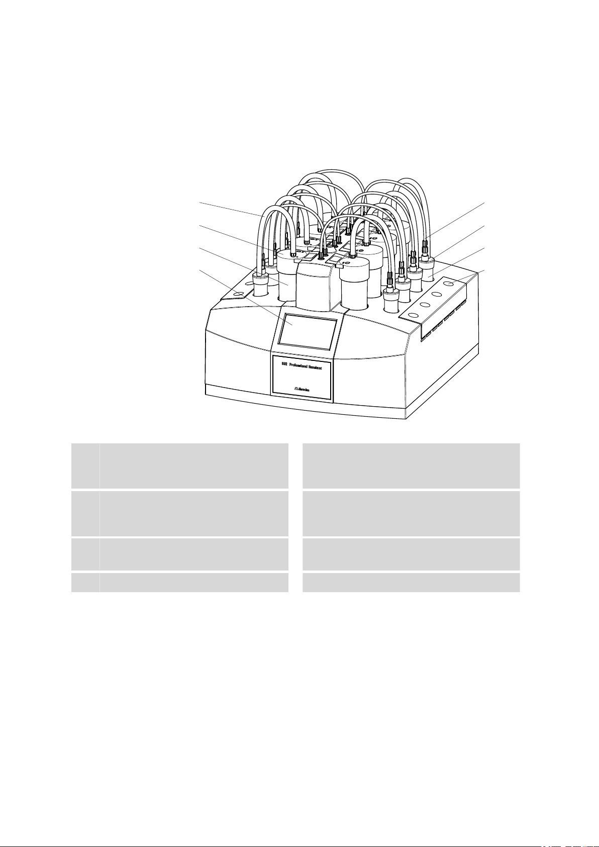
Figure 1 Front 892 Professional Rancimat
Silicone tubing (6.1816.010)
1
For connecting the reaction vessel to the
measuring vessel.
Measuring vessel (6.1428.107)
3
FEP tubing 250 mm (6.1805.080)
5
For supplying air into the reaction vessel.
Reaction vessels (6.1429.040)
7
Measuring vessel cover (6.0913.130)
2
Contains an integrated conductivity measuring cell.
Instrument display
4
Displays the status of the instrument and the
individual measuring positions.
Reaction vessel cover (6.2753.107)
6
Start buttons
8
■■■■■■■■
6
892 Professional Rancimat
Page 15
■■■■■■■■■■■■■■■■■■■■■■
1
2
3
4
5
6
7
8
9
10 11 12 13 14 15 16 17 18 19 20
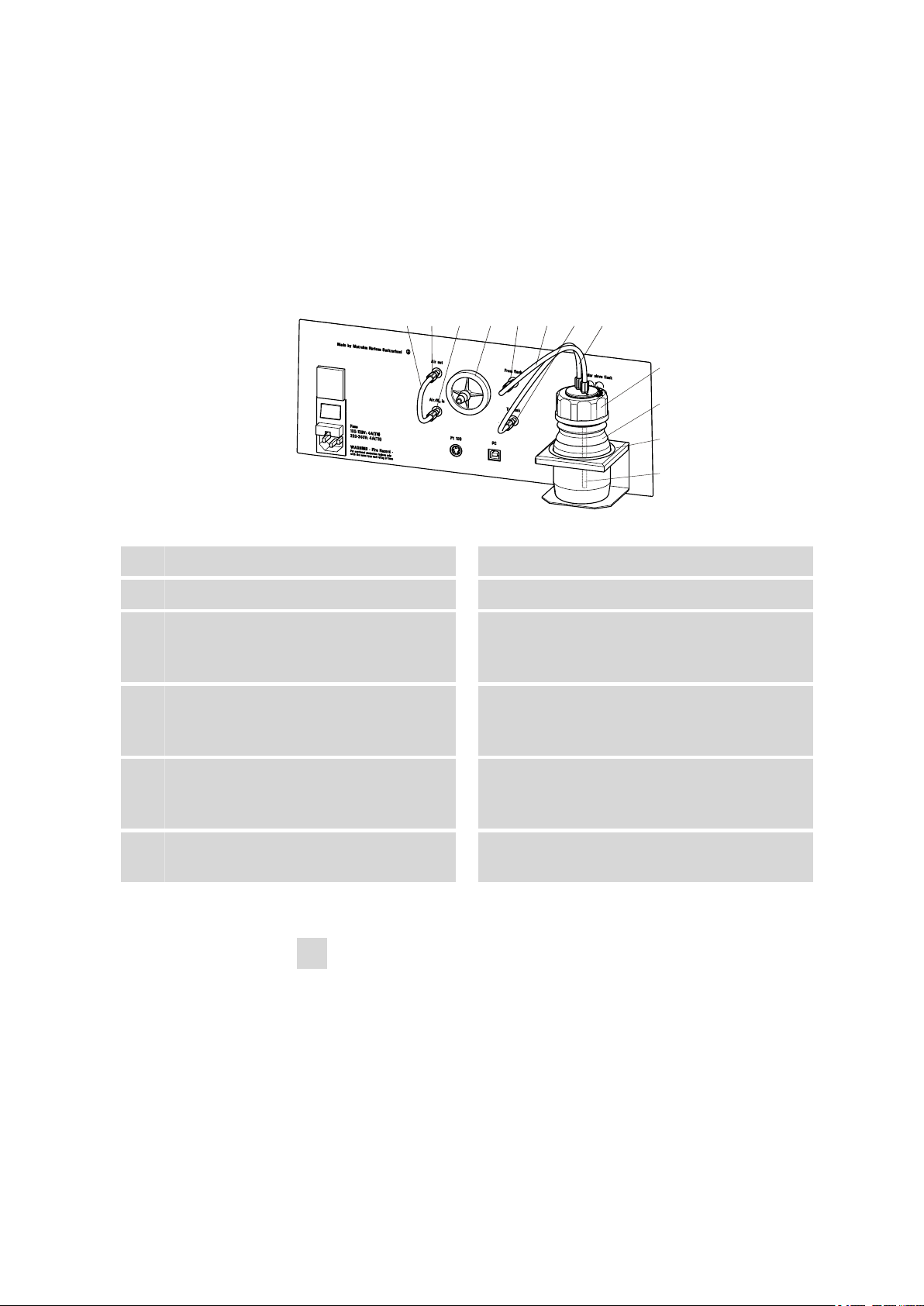
2.2 Rear of the instrument
2 Overview of the instrument
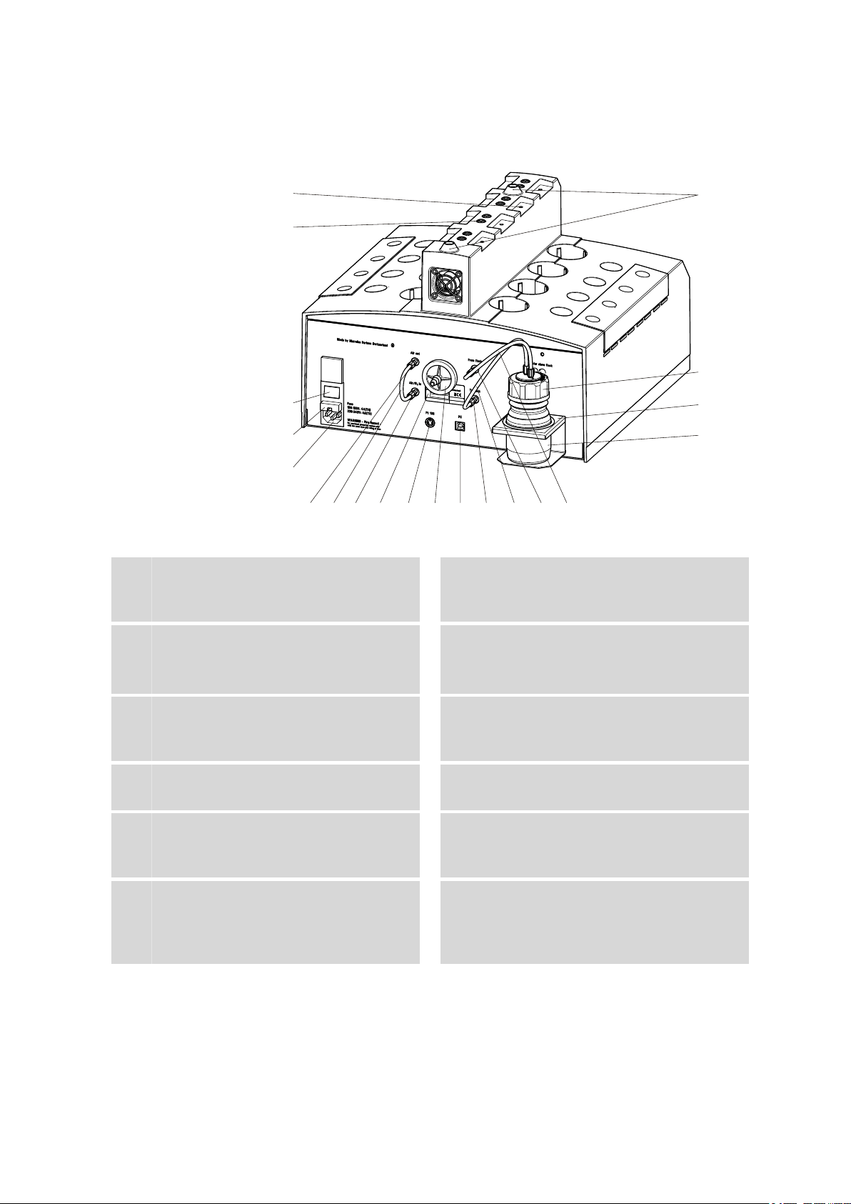
Figure 2 Rear 892 Professional Rancimat
Electrode connector
1
For connecting the conductivity measuring
cell integrated in the measuring vessel cover.
Power switch
3
For switching the instrument on and off.
I = ON / 0 = OFF.
Power socket
5
For important information on the power
connection, see Chapter 3.3.
Drying flask cap (6.1602.145)
7
Cap for the drying flask.
Drying flask (6.1608.050)
9
Drying flask filled with molecular sieve
(6.2811.000).
FEP tubing 130 mm (6.1805.010)
11
For connecting the Air out connector to the
Air/N2 in connector during normal opera-
tion with the internal air pump.
Air supply connector
2
For connecting the FEP tubing 250 mm.
Fuse holder
4
For replacing fuses (see Chapter 3.3.1, page
21).
Collection tube holder
6
For fastening the optional exhaust air collection tube (6.2757.000).
Bottle holder
8
For fastening the drying flask.
"Air out" connector
10
"Air/N2 in" connector
12
892 Professional Rancimat
■■■■■■■■
7
Page 16
2.3 Instrument display
892_1
1 2 3 4
9 8 7 6
10
5
■■■■■■■■■■■■■■■■■■■■■■
Type plate
13
Contains specifications concerning supply
voltage and serial number.
Dust filter (6.2724.010)
15
"To flask" connector
17
"From flask" connector
19
2.3 Instrument display
Pt100 connector
14
For connecting an external temperature sensor.
USB connector
16
For connecting the computer.
FEP tubing 250 mm (6.1805.080)
18
For supplying the air from the internal pump
to the drying flask.
FEP tubing 250 mm (6.1805.080)
20
For supplying the air from the drying flask to
the reaction vessels.
1
3
■■■■■■■■
8
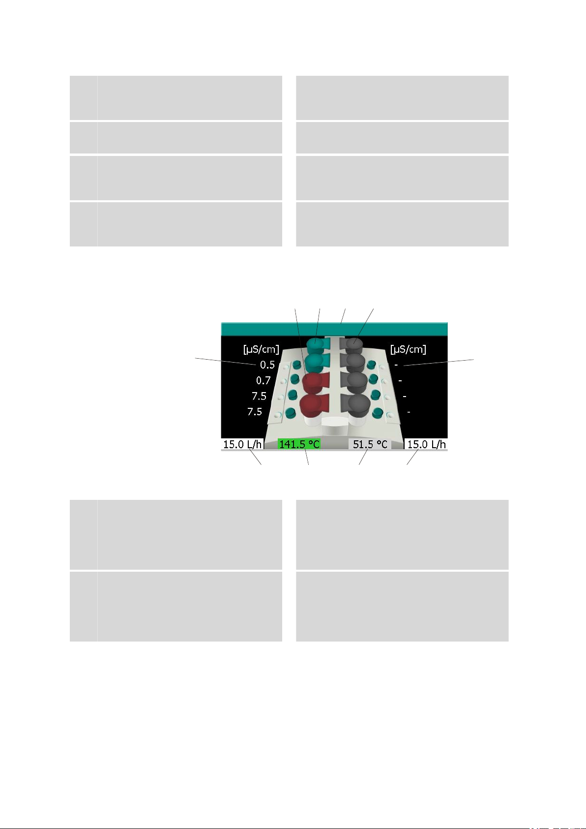
Figure 3
Measuring vessel cover red
This measuring position is not available for a
determination (determination is running or
multiple determination has not yet been
completed).
Instrument name
The instrument name display corresponds to
the configuration in StabNet.
Instrument display
Measuring vessel cover green
2
A determination can be started on this measuring position.
Measuring vessel cover gray
4
This measuring position is not available for
starting a determination (instrument not
connected to computer or no method loaded).
892 Professional Rancimat
Page 17

■■■■■■■■■■■■■■■■■■■■■■
2 Overview of the instrument
Conductivity display block B
5
Shows the measured conductivity.
Dash (-) is displayed = Conductivity cannot
be displayed (no sensor connected or no
valid measuring signal).
Temperature display block B
7
Shows the temperature measured on block
B (gray background: heater switched off; red
background: temperature not stable; green
background: temperature stable).
Gas flow display block A
9
Shows the gas flow measured on block A
(gray background: gas flow switched off;
white background: gas flow switched on).
Gas flow display block B
6
Shows the gas flow measured on block B
(gray background: gas flow switched off;
white background: gas flow switched on).
Temperature display block A
8
Shows the temperature measured on block
A (gray background: heater switched off;
red background: temperature not stable;
green background: temperature stable).
Conductivity display block A
10
Shows the measured conductivity.
Dash (-) is displayed = Conductivity cannot
be displayed (no sensor connected or no
valid measuring signal).
892 Professional Rancimat
■■■■■■■■
9
Page 18

3.1 Setting up the instrument
3 Installation
3.1 Setting up the instrument
3.1.1 Packaging
The instrument is supplied in highly protective special packaging together
with the separately packed accessories. Keep this packaging, as only this
ensures safe transportation of the instrument.
3.1.2 Checks
Immediately after receipt, check whether the shipment has arrived complete and without damage by comparing it with the delivery note.
3.1.3 Location
The instrument has been developed for operation indoors and may not be
used in explosive environments.
■■■■■■■■■■■■■■■■■■■■■■
Place the instrument in a location of the laboratory which is suitable for
operation and free of vibrations and which provides protection against
corrosive atmosphere and contamination by chemicals to the extent possible.
The instrument should be protected against excessive temperature fluctuations and direct sunlight.
NOTE
In order to improve accessibility of the measuring positions, the instrument can also be placed on the optionally available turning ring
(6.2059.000).
■■■■■■■■
10
892 Professional Rancimat
Page 19
■■■■■■■■■■■■■■■■■■■■■■
1 2 3 4 5 6 7 8
9
10
11
12
3.2 Mounting accessories
3.2.1 Mounting the internal air supply
The gas in the 892 Professional Rancimat is normally supplied using the
internal air pump, which aspirates laboratory air. For air supply and
air purification, the following accessories must be mounted on the rear of
the 892 Professional Rancimat:
3 Installation
Figure 4 Mounting accessories for the air supply
FEP tubing 130 mm (6.1805.010)
1
"Air/N2 in" connector
3
"From flask" connector
5
"To flask" connector
7
Drying flask cap (6.1602.145)
9
Cap for the drying flask.
Bottle holder
11
For fastening the drying flask.
Mount the accessories for the air supply as follows:
"Air out" connector
2
Dust filter (6.2724.010)
4
FEP tubing 250 mm (6.1805.080)
6
For supplying the air from the drying flask to
the reaction vessel.
FEP tubing 250 mm (6.1805.080)
8
For supplying the air from the internal pump
to the drying flask.
Drying flask (6.1608.050)
10
Drying flask filled with molecular sieve
(6.2811.000).
Filter tube (6.1821.040)
12
1
Mounting the dust filter
■ Insert the dust filter on the connector marked with Filter on the
rear of the 892 Professional Rancimat.
■ If the laboratory air is heavily contaminated, a tubing for supply-
ing fresh air can be connected to the dust filter.
892 Professional Rancimat
■■■■■■■■
11
Page 20
3.2 Mounting accessories
■■■■■■■■■■■■■■■■■■■■■■
NOTE
The dust filter serves for filtering the air aspirated through the air
pump and must be replaced at periodic intervals (see Chapter 5.2,
page 41).
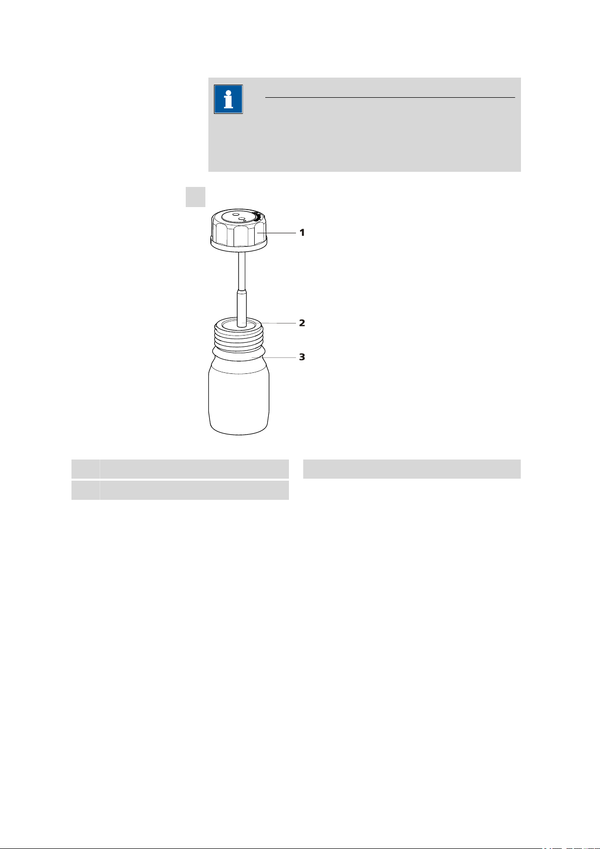
2
Mounting the drying flask
Drying flask cap (6.1602.145)
1
Bottle (6.1608.050)
3
Figure 5 Drying flask - Individual parts
Filter tube (6.1821.040)
2
■ Fill the molecular sieve into the drying flask.
■ Screw the filter tube on the bottom side of the drying flask cap
into the opening marked with a dot (on the upper side).
■ Screw the drying flask cap with mounted filter tube onto the dry-
ing flask and insert it in the flask holder on the rear of the 892
Professional Rancimat.
■ Screw one end of the FEP tubing 250 mm to the opening on the
drying flask cap marked with a dot.
■ Screw the other end of the FEP tubing to the From flask connec-
tor on the rear of the 892 Professional Rancimat.
■ Screw one end of the second FEP tubing 250 mm to the second
opening on the drying flask cap.
■ Screw the other end of the second FEP tubing to the To flask
connector.
■■■■■■■■
12
892 Professional Rancimat
Page 21

■■■■■■■■■■■■■■■■■■■■■■
3 Installation
Figure 6 Drying flask mounted in place
NOTE
The molecular sieve serves to adsorb interfering oxidizing gases as
well as water from the aspirated air.
You can regenerate it in the drying oven at +140 - +180 °C for 24
to 48 h (see Chapter 5.3, page 41).
3
Mount the FEP tubing for the air supply
■ Screw one end of the FEP tubing 130 mm to the Air out connec-
tor.
■ Screw the other end of the FEP tubing to the Air/N
tor.
3.2.2 Mounting the external air supply
If the laboratory air is heavily contaminated, an external gas supply with
synthetic air can be provided.
For this, the corresponding accessories must be mounted on the rear of
the 892 Professional Rancimat.
NOTE
If air is supplied externally, the gas flow cannot be regulated in the
computer program.
in connec-
2
892 Professional Rancimat
The gas flow must be set manually using the reducing valve and the gas
flow display.
■■■■■■■■
13
Page 22

3.2 Mounting accessories
Mount the accessories for the external air supply as follows:
1
Mounting the FEP tubing
■ Screw one end of the FEP tubing 130 mm to the Air/N
nector (2-12) on the rear of the 892 Professional Rancimat.
■ Screw the tubing adapter M6/olive (6.1808.020) onto the other
end of the FEP tubing.
2
Connecting the gas supply
■ Mount the compressed air bottle on the M6/olive tubing adapter
(6.1808.020).
■ Adjust the air flow by means of the reducing valve at the com-
pressed air bottle.
3.2.3 Assembling the reaction and measuring vessels
The following figure shows in detail how the accessory parts for measuring the oxidation stability have to be mounted and connected to one
another.
■■■■■■■■■■■■■■■■■■■■■■
in con-
2
■■■■■■■■
14
892 Professional Rancimat
Page 23

■■■■■■■■■■■■■■■■■■■■■■
1
2
3
4
5
6
7
8
9
10
11
12
13
14
15
16
17
18
19
20
3 Installation
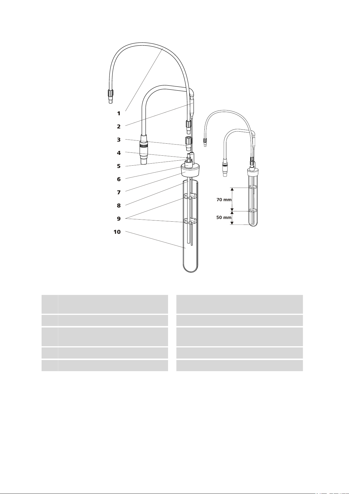
Figure 7 Equipping the reaction and measuring vessels
FEP tubing 250 mm (6.1805.080)
1
For supplying air into the reaction vessel.
Thread adapter M8/M6 (6.1808.090)
3
Air tube (6.2418.100)
5
Thread adapter M8/M6 connector
7
Foam barrier (6.1451.010)
9
Optional foam barrier.
Tubing adapter M8/olive (6.1808.050)
11
For connecting the silicone tubing to the In
opening.
Opening "In"
13
For supplying the air to the measuring vessel.
Connector plug
15
892 Professional Rancimat
Silicone tubing (6.1816.010)
2
For connecting the reaction vessel to the
measuring vessel.
O-ring (6.1454.040)
4
Tubing connector
6
For connecting the silicone tubing.
Reaction vessel cover (6.2753.107)
8
Reaction vessel (6.1429.040)
10
Opening "Out"
12
For removing the air from the measuring
vessel.
Label field
14
For attaching labels (e.g. 6.2250.000 laminated labels).
Measuring vessel cover (6.0913.130)
16
Contains an integrated conductivity measuring cell.
■■■■■■■■
15
Page 24

3.2 Mounting accessories
■■■■■■■■■■■■■■■■■■■■■■
PTFE cannula (6.1819.080)
17
For supplying the air to the measuring solution.
Protection ring
19
Proceed as follows to mount the measuring vessel and the reaction vessel:
1
Mounting the measuring vessel cover
■ Screw the PTFE cannula from above into the In opening of the
■ Screw the M8/olive tubing adapter into the In opening of the
■ Pour 50 - 80 mL of deionized water into the measuring vessel (the
■ Place the measuring vessel cover onto the measuring vessel.
2
Mounting the reaction vessel cover
■ Place the O-ring (6.1454.040) over the upper end of the air tube.
■ Feed the air tube (6.2418.xx0) into the connector of the reaction
■ Gently screw the M8/M6 thread adapter into the connector while
■ Optional: If determinations are being carried out with highly
■ Blow out the reaction vessel with nitrogen to free it from foreign
■ Before putting the cover in place, briefly rotate the upper part of
■ Place the reaction vessel cover on the reaction vessel.
Electrode
18
Measuring vessel (6.1428.107)
20
measuring vessel cover.
measuring vessel cover.
exact quantity depends on the application).
vessel cover (6.2753.107) from above.
pressing the air tube against the thread adapter from below. Then
fix the air tube onto the reaction vessel cover by firmly tightening
the thread adapter.
foaming samples, clamp the foam barrier (6.1451.010) onto the
air tube.
substances (e.g. dust or cardboard shreds).
the reaction vessel in your hand. This slightly lubricates the glass
and facilitates removal of the covers after the measurement.
■■■■■■■■
16
NOTE
When mounted without foam barrier, the air tube must be in a vertical
position in the reaction vessel.
892 Professional Rancimat
Page 25

■■■■■■■■■■■■■■■■■■■■■■
3 Installation
Figure 8 Mounting the air tube: correct - incorrect
WARNING
The foam barrier can melt if it projects too deeply into the heating
block.
Ensure that the foam barrier is at least 7 cm above the base of the
reaction vessel.
Figure 9
Mounting the foam barrier
3.2.4 Inserting vessels / Establishing tubing connections
After you have assembled the reaction and measuring vessels, insert them
in the 892 Professional Rancimat and establish the tubing connections
(see Chapter 2.1, page 6) as follows:
1
Inserting the measuring vessel
■ Fill distilled water into the measuring vessel.
■ Place the measuring vessel cover onto the measuring vessel.
■ Insert the measuring vessel into the openings provided on the 892
Professional Rancimat. While doing so, carefully guide the connector plug into the electrode connector.
■ Connect the white silicone tubing to the M8/olive tubing adapter
of the measuring vessel cover.
892 Professional Rancimat
■■■■■■■■
17
Page 26

3.2 Mounting accessories
■■■■■■■■■■■■■■■■■■■■■■
2
Mounting the tubing for the air supply
■ Screw the FEP tubing 250 mm to the air supply connections of
the 892 Professional Rancimat.
3
Inserting the reaction vessel
■ Fill the reaction vessel with the sample.
■ After the required reaction temperature has been reached, insert
the reaction vessel with the mounted reaction vessel cover in the
openings provided on the 892 Professional Rancimat.
4
Establishing the tubing connections
■ Connect the white silicone tubing that is connected to the mea-
suring vessel cover to the tubing connector of the reaction vessel
cover.
■ Screw the FEP tubing 250 mm which is connected to the M8/olive
tubing adapter of the 892 Professional Rancimat to the M8/M6
thread adapter of the reaction vessel cover.
NOTE
The optional clear glass measuring vessels (6.1428.030) [Link target not
found in publication context!] may also be used in place of the polystyr-
ene measuring vessel (6.1428.107).
In contrast to the polystyrene vessel, the measuring vessel (6.1428.030)
can also be cleaned with acetone.
3.2.5 Mounting the exhaust air collection tube
The optional exhaust air collection tube (6.2757.000) [Link target not
found in publication context!] can be mounted on the 892 Professional
Rancimat for targeted removal of the exhaust air.
NOTE
A total of 8 pieces of silicone tubing (6.1816.010) (220 mm) are
required in addition to the exhaust air collection tube.
■■■■■■■■
18
892 Professional Rancimat
Page 27

■■■■■■■■■■■■■■■■■■■■■■
Proceed as follows to mount the collection tube:
1
Mounting the exhaust air collection tube
■ Insert the exhaust air collection tube with both support pins into
the collection tube holders on the 892 Professional Rancimat in
such a way that the connector to the exhaust air removal is
located to the rear.
2
Connecting the measuring vessels
■ Screw the M8/olive tubing adapter into the Out opening of the
measuring vessel cover.
■ Connect one end of the silicone tubing to the M8/olive tubing
adapter.
■ Insert the other end of the silicone tubing into the corresponding
opening on the collection tube.
■ Seal the unused openings on the collection tube with the
enclosed stoppers.
3
Connecting the exhaust air collection tube
■ Connect a suitable tubing to the connector of the exhaust air col-
lection tube and connect it to an active suction device (e.g. water
jet pump).
3 Installation
3.2.6 Mounting the oil separator
If samples with a high content of highly volatile compounds are used,
there is a risk that the sample is transferred to the measuring vessel in the
vapor phase. This can compromise the conductivity measurement. The
amount of oil contained in the vapor phase can be reduced by means of
the oil separator (6.2753.200). The use of the oil separator is recommended if the conductivity measurement is compromised by the presence of
the sample in the measuring vessel [Link target not found in publication
context!].
NOTE
An additional 8 pieces of silicone tubing (6.1816.010) are required if 8
oil separators are used.
NOTE
The oil separators must be cleaned after each measurement (see Chapter 4.3.5, page 38).
892 Professional Rancimat
■■■■■■■■
19
Page 28

3.2 Mounting accessories
1
2
3
4 5
■■■■■■■■■■■■■■■■■■■■■■
Figure 10 Mounting the oil separator
Oil separator (6.2753.200)
1
Oil separator with sealing cover (bottom).
Measuring vessel
3
Silicone tubing to the measuring vessel
5
Proceed as follows to mount the oil separator:
1
Clamping the oil separator in place
■ Clamp an oil separator in place on the side of each reaction vessel
2
Attaching the silicone tubing to the oil separator
■ Attach one end of the silicone tubing to the tubing connector of
■ Attach the other end of the silicone tubing to the inlet opening IN
3
Attaching the silicone tubing to the measuring vessel
■ Attach one end of the silicone tubing to the outlet opening OUT
■ Attach the other end of the silicone tubing to the tubing connec-
Reaction vessel
2
Silicone tubing to the oil separator
4
(sealing cover on the bottom).
the reaction vessel.
of the oil separator.
of the oil separator.
tor of the measuring vessel.
■■■■■■■■
20
892 Professional Rancimat
Page 29

■■■■■■■■■■■■■■■■■■■■■■
3.3 Power socket
There is a risk of fire if the instrument is operated with an incorrect
mains fuse!
Follow the regulations below for the mains connection.
3.3.1 Replacing fuses
The fuse holder of the 892 Professional Rancimat contains two fuses:
■ Two slow-acting 4 A fuses
Ensure that the instrument is never put into operation with fuses of
another type, otherwise there is a risk of fire!
3 Installation
WARNING
WARNING
Proceed as follows to replace defective fuses:
1
Pulling out the power supply cable
■ Pull the power supply cable out of the power socket of the 892
Professional Rancimat.
2
Removing the fuse holder
■ Release the fuse holder located on the rear of the instrument
above the power socket by pressing the catch spring and pull out
the holder completely.
3
Replacing the fuses
■ Carefully remove the defective fuses from the fuse holder and
replace them with two new slow-acting 4 A fuses:
4
Inserting the fuse holder
■ Push the fuse holder back into the instrument until it latches into
place.
892 Professional Rancimat
■■■■■■■■
21
Page 30

3.3 Power socket
3.3.2 Power supply cable and power socket
Power supply cable
The instrument is supplied with a three-core power supply cable and a
plug with protective grounding. If another plug has to be mounted, then
the yellow/green conductor (IEC standard) must be connected to the protective ground (protection class 1).
WARNING
Any interruption to the grounding within or outside the instrument can
make it dangerous!
Power socket
Plug the power supply cable into the power socket (2-5) of the 892 Professional Rancimat.
3.3.3 Switching the instrument on and off
The 892 Professional Rancimat is switched on and off using the power
switch (2-3). The instrument display is switched on when the instrument is
switched on.
■■■■■■■■■■■■■■■■■■■■■■
■■■■■■■■
22
Figure 11
Instrument display with instrument name
The instrument 892 Professional Rancimat has been recognized by the
StabNet computer program and the instrument name entered has been
transmitted.
Figure 12
Instrument display with "no connection" symbol
The USB connection between the instrument 892 Professional Rancimat
and the computer has been interrupted and the corresponding symbol is
displayed.
892 Professional Rancimat
Page 31

■■■■■■■■■■■■■■■■■■■■■■
3 Installation
Figure 13 Instrument display without instrument name and symbol
The instrument 892 Professional Rancimat is connected to the computer
but the StabNet computer program has been closed.
Figure 14
Instrument display with serial number
The instrument 892 Professional Rancimat has been started, but the StabNet computer program was not previously started.
3.4 Connecting a computer
3.4.1 Connecting the 892 Professional Rancimat and the computer
NOTE
The StabNet computer program has to be installed before you can
connect the instrument to the computer.
The StabNet computer program allows you to control up to 4 instruments.
Connect and set up the 892 Professional Rancimat as follows:
Establish a connection between the USB interface (2-16) of the 892
1
Professional Rancimat and the required USB interface on the computer using the USB cable (6.2151.130).
Start the StabNet computer program.
2
Switch on the 892 Professional Rancimat using the power switch.
3
892 Professional Rancimat
■■■■■■■■
23
Page 32

3.4 Connecting a computer
■■■■■■■■■■■■■■■■■■■■■■
Wait for the instrument 892 Professional Rancimat to be detected
4
and installed.
Enter the instrument information into the dialog fields of the 892
5
Professional Rancimat configuration.
NOTE
You will find detailed information regarding the StabNet computer program in the Tutorial.
The instrument name entered in the configuration must appear on
the instrument display (3-3).
■■■■■■■■
24
892 Professional Rancimat
Page 33

■■■■■■■■■■■■■■■■■■■■■■
4 Operation
4.1 Rancimat method
The decay of vegetable and animal fats, which can be perceived in the initial stage through a deterioration of odor and taste (rancidity), is to a
great extent the result of chemical modifications caused by the effect of
atmospheric oxygen. These oxidation processes, which progress slowly at
ambient temperatures, are referred to as autoxidation. They start with
radical reactions on unsaturated fatty acids and undergo a process involving multiple stages resulting in diverse decomposition products, in particular peroxides as primary oxidation products and alcohols, aldehydes and
carboxylic acids as secondary oxidation products.
In the Rancimat method, the sample is exposed to an air flow at a constant temperature between 100 - 140 °C. Highly volatile, secondary oxidation products (for the most part formic acid and acetic acid) are transferred into the measuring vessel with the air flow, where they are absorbed
in the measuring solution (distilled water). Here the conductivity is continuously registered. The organic acids can thus be detected by an increase
in the conductivity. The time until these secondary reaction products occur
is referred to as the induction time or induction period, which is a good
characteristic for the oxidation stability.
4 Operation
The Rancimat method has been developed as an automated variant of the
extremely complex AOM (active oxygen method) for determining the
induction time of fats and oils. This method has become established
over the course of time and has been incorporated in various national and
international standards, e.g. AOCS Cd 12b-92 and ISO 6886.
892 Professional Rancimat
■■■■■■■■
25
Page 34

4.2 Calibration functions
■■■■■■■■■■■■■■■■■■■■■■
Figure 15 Measuring arrangement (schematic representation)
Reaction vessel
1
Heating block
3
Conductivity measuring cell
5
4.2 Calibration functions
4.2.1 Determining the cell constant
The cell constant of the conductivity sensor (6.0913.130) is normally at
1.1 ± 0.1 cm-1. This accuracy is sufficient for an induction time determination since only the shape of the curve is evaluated. For the determination of the stability time, however, the conductivity change is measured
in absolute terms. As a rule, the time until an increase in conductivity of
50 µS/cm is determined. The cell constant for the conductivity electrode
being used has to be calibrated in order to be able to measure the conductivity correctly.
Sample
2
Measuring vessel
4
Measuring solution
6
■■■■■■■■
26
892 Professional Rancimat
Page 35

■■■■■■■■■■■■■■■■■■■■■■
The cell constants can be either entered manually or determined automatically by means of a defined standard solution, e.g. the conductivity standard 100 µS/cm (6.2324.010).
NOTE
You will find detailed information regarding the StabNet computer
program in the Tutorial.
4.2.2 Determining the temperature correction
Temperature correction indicates the deviation of the current sample
temperature from the temperature of the heating block and forms part of
the method as a parameter.
It can be determined automatically with the calibrated, external temperature sensor.
4 Operation
892 Professional Rancimat
■■■■■■■■
27
Page 36
4.2 Calibration functions
■■■■■■■■■■■■■■■■■■■■■■
■■■■■■■■
28
Figure 16 Assembling the reaction vessel for determining the tempera-
FEP tubing 250 mm (6.1805.080)
1
For supplying air into the reaction vessel.
Thread adapter M8/M6 (6.1808.090)
3
Temperature sensor opening
5
For inserting the temperature sensor.
Reaction vessel cover (6.2753.107)
7
Spacer (6.2042.040)
9
ture correction
Pt100 temperature sensor
2
(6.1111.010)
O-ring (6.1454.040)
4
Connector
6
For connecting the thread adapter M8/M6.
Air tube (6.2418.100)
8
Reaction vessel (6.1429.040)
10
892 Professional Rancimat
Page 37

■■■■■■■■■■■■■■■■■■■■■■
4 Operation
Preparing the determination of the temperature correction
The figure shows in detail how the accessory parts are to be assembled
for the determination of the temperature correction. Proceed as follows:
1
Preparing the reaction vessel cover
■ Mount the air tube on the reaction vessel cover.
■ Clamp the first spacer at a distance of approx. 12 cm from the
lower end onto the air tube.
■ Clamp the second spacer at a distance of approx. 5 cm from the
lower end onto the air tube.
■ Insert the temperature sensor from above into the temperature
sensor opening and fasten it in the corresponding openings of the
spacers.
2
Preparing the reaction vessel
■ Fill the reaction vessel with 6 g silicone oil (6.2326.000).
■ Place the reaction vessel cover with the temperature sensor on
the reaction vessel.
■ Push the temperature sensor all the way down (the sensor must
touch the vessel base).
3
Inserting and connecting the reaction vessel
■ Insert the reaction vessel with the mounted reaction vessel cover
in the measuring position 2 or 3 of the required heating block.
■ Screw one end of the FEP tubing 250 mm to the M8/M6 thread
adapter of the reaction vessel cover.
■ Screw the other end of the FEP tubing to the corresponding con-
nector of the 892 Professional Rancimat.
■ Connect the temperature sensor to the Pt100 connector (2-14)
on the rear of the 892 Professional Rancimat.
892 Professional Rancimat
NOTE
You will find detailed information regarding the StabNet computer
program in the Tutorial.
■■■■■■■■
29
Page 38

4.3 Determinations
4.3 Determinations
4.3.1 Preparing a sample
Use new reaction vessels and air tubes for each measurement.
Blow out the reaction vessels with nitrogen before use.
This chapter contains information on how to prepare the following samples:
■ Pure, clear oils (see page 30)
■ Non-liquid, pure fats (see page 30)
■ Samples containing oil and fat (see page 31)
■ Emulsion fats (see page 33)
■ Solid samples (e.g. PVC) (see page 34)
■■■■■■■■■■■■■■■■■■■■■■
NOTE
Preparing pure, clear oils
Prepare oil that is completely pure and clear as follows:
1
Weighing in the sample
■ Place the reaction vessel on a scale using a 6.2628.000 holder.
■ Weigh the sample material directly in the reaction vessel.
Normally, 3 g of sample material are used for vegetable oils.
2
Checking the filling level
■ Make sure that the quantity of sample material in the reaction
vessel is sufficient so that the air tube is immersed deeply enough.
If this is not the case, add more sample material.
Preparing non-liquid, pure fats
Prepare non-liquid, pure fat as follows:
1
Weighing in the sample
either
■■■■■■■■
30
■ Completely liquefy the fat in a water bath or in a drying oven at
a temperature exceeding its melting point by 10 °C.
■ Place the reaction vessel on a scale using a 6.2628.000 holder.
892 Professional Rancimat
Page 39

■■■■■■■■■■■■■■■■■■■■■■
4 Operation
■ Then transfer 3 g sample material to the reaction vessel using
preheated pipettes.
or
■ Place the reaction vessel on a scale using a 6.2628.000 holder.
■ Weigh in the fat as solid.
For this, weigh in 3 g sample material directly in the reaction
vessel and insert it briefly in the heated block of the 892 Professional Rancimat, so that the fat melts.
2
Checking the filling level
■ Make sure that the quantity of melted sample material in the
reaction vessel is sufficient so that the air tube is immersed deeply
enough. If this is not the case, add more sample material.
Preparing samples containing oil and fat
Oils and fats made from products containing oil and fat must be extracted
with petroleum ether (low-boiling) while being protected from light as follows:
1
Crushing the samples
■ Finely and homogeneously grind oilseed fruit, cocoa beans as well
as other solids in coarse form in a knife mill or another suitable
crushing apparatus (if possible, metal-free).
NOTE
Oil/fat extraction through pressing has not proven effective in
practice.
2
Extraction
■ Prepare a 300 mL Erlenmeyer flask with standard ground-joint.
■ Weigh in between 50 and 100 g (depending on the oil/fat con-
tent) of the sample in powder form (e.g. milk powder, cocoa
powder, hazelnut powder) or the finely ground material.
■ Cover the sample material with a layer of approx. 1 cm of petro-
leum ether (low-boiling).
■ Extract the oil or fat while continuously stirring for around 12 h
and keeping it protected from light.
892 Professional Rancimat
■■■■■■■■
31
Page 40

4.3 Determinations
■■■■■■■■■■■■■■■■■■■■■■
NOTE
In order to carry out at least one double determination on the 892
Professional Rancimat, you have to extract approx. 10 g pure oil or
fat, allowing for a certain transfer loss (for more than two determinations, an accordingly higher amount is necessary).
■ Prepare a clean 250 mL round-bottom flask with standard
ground-joint and a folded filter.
■ Filtrate, if possible protected from light. Rewash the residue with
a little petroleum ether.
NOTE
If the folded filter becomes blocked (e.g. due to the consistency of
the sample material), a Soxhlet apparatus should be used for solid/
liquid separation. You can use up to 40 g of sample material per
batch.
3
Distillation and filtration
■ Distill the petroleum ether from the clear, perhaps slightly yellow
extract.
NOTE
It is safest and easiest if you do this in a rotary evaporator; in a
slight vacuum, protected from direct light (cover the water bath
e.g. with aluminum foil) and at a temperature of +30 - 35 °C the
petroleum ether can gently and efficiently be removed.
■ Dry the oil/fat sample after the distillation has been completed for
approx. 30 min at a pressure of < 1,330 Pa (13.3 mbar).
■ Filtrate the oil/fat sample now present together with water-free
Na2SO4 with a folded filter. If necessary, work in the drying oven
at a temperature exceeding the melting point of this fat by 10 °C.
4
Further sample preparation
■ Treat the isolated oil/fat samples afterwards just as pure oils and
fats.
■■■■■■■■
32
892 Professional Rancimat
Page 41

■■■■■■■■■■■■■■■■■■■■■■
4 Operation
NOTE
If the isolated oil/fat samples are not immediately analyzed, you
have to store the samples in a cool place and protected from
light; for storing the samples, you should cover them in their vessels with a nitrogen layer. This type of storage does not provide
complete protection against unintended and uncontrolled changes
in the oxidation stability, but it represents a useful preservation in
many cases.
You can find further information on the treatment of oil and fat samples
in Rancidity in Foods, Allen J.C., Hamilton R.J., Applied Science Publish-
ers, London and New York, 1983.
Preparing emulsion fats
You can use emulsion fats like pure substances and prepare them as follows:
1
Weighing in the sample
■ Weigh in the sample.
NOTE
As the water evaporates right at the beginning of the analysis and
is carried away by the air blown through, you have to use correspondingly more sample material.
2
Mounting the foam barrier
■ Mount the foam barrier (see figure 9, page 17), as the samples
can foam heavily.
NOTE
If the emulsion fat samples are not immediately analyzed, you
need to store the samples in a cool place and protected from
light; for storing the samples, you should cover them in their vessels with a nitrogen layer. This type of storage does not provide
complete protection against unintended and uncontrolled changes
in the oxidation stability, but it provides useful preservation in
many cases.
892 Professional Rancimat
■■■■■■■■
33
Page 42

4.3 Determinations
Solid samples (e.g. nuts)
Prepare the sample as follows:
Place the reaction vessel on a scale using a 6.2628.000 holder.
1
If necessary, pulverize the sample material and weigh it directly in the
2
reaction vessel. Normally, 0.5 g of sample material is used.
Alternatively you can melt the emulsion fats (e.g. butter, margarine) at a
temperature exceeding the melting point of these fats by 10 °C (i.e. at
approx. +50 °C) centrifuge them and pipette off the resultant oil phase.
4.3.2 Preparing the instrument and the accessories
The cleanliness of instrument and accessory parts is an indispensable prerequisite for reliable, reproducible and correct analysis results. Even
the slightest contamination could catalytically accelerate the oxidative
decomposition and lead to completely incorrect results. Therefore, always
observe the instructions for use of measuring and reaction vessels in this
chapter.
■■■■■■■■■■■■■■■■■■■■■■
Check and prepare the instruments and vessels as follows:
1
Checking the positions for reaction vessels
■ Check whether the positions in the heating block are clean and
empty.
Blow out contamination and dust in the positions with nitrogen.
If the instrument is not used, always seal the corresponding positions with the stoppers.
2
Filling the measuring vessels
NOTE
Only use measuring vessels and accessories which are absolutely clean and in a flawless condition.
■ Fill the cleaned measuring vessels with 60 mL distilled water
each.
For analysis times of more than 24 h approx. 7 mL more distilled
water must be added per day to compensate for the evaporation
loss, so that the electrodes remain safely immersed.
■■■■■■■■
34
892 Professional Rancimat
Page 43

■■■■■■■■■■■■■■■■■■■■■■
3
Inserting the measuring vessels
■ Place the clean measuring vessel covers equipped with a PTFE
cannula on the measuring vessels.
■ Insert the measuring vessels with the measuring vessel covers into
the openings provided for this on the 892 Professional Rancimat
while carefully guiding the connector plugs of the cover into the
electrode connectors.
4
Weighing in samples
NOTE
Use new reaction vessels and air tubes for each measurement. Blow out the reaction vessels with nitrogen before use so
that any adhering particles are removed.
■ Weigh in 3 g of the samples in each reaction vessel (see Chap-
ter 4.3.1, page 30).
5
Mounting the accessories
■ Hold the upper edge of the reaction vessel in your hand (e.g. in
the recess between your thumb and index finger) and rotate the
glass once.
This serves to cover the degreased glasses with a light fat film so
that the vessel covers can be removed more easily after the determination.
■ Insert an air tube into the connector of the reaction vessel cover,
fix it with the O-ring and fasten it by screwing in the M8/M6
thread adapter.
■ Place the reaction vessel cover on the reaction vessel. Turn the
cover in such a way that the air tube is as close as possible to the
vessel wall.
■ Connect the white silicone tubing to the tubing connector of the
reaction vessel cover.
■ Place the prepared reaction vessel in the vessel holder.
4 Operation
4.3.3 Preparing the determination
1
Selecting the method (StabNet)
■ In the Workplace program part, click on the symbol within the
block A area and select a Method for block A.
■ If required, also select a method for block B.
892 Professional Rancimat
■■■■■■■■
35
Page 44

4.3 Determinations
■■■■■■■■■■■■■■■■■■■■■■
NOTE
Different methods with different temperatures can be selected for
block A and block B.
The gas flow for the two blocks A and B cannot be switched on
and off individually for each block but only collectively. If methods
with different gas flows are loaded on the two blocks, then the
value from the block in which the gas flow is switched on is used.
2
Starting the heater (StabNet)
■ In the Workplace program part, click on the [Start] button for
Heater within the block A area.
■ If required, also switch on the heater for Block B.
The color of the temperature display on the 892 Professional Rancimat changes to red during the heating phase.
The color of the temperature display on the 892 Professional Rancimat changes to green once the setpoint temperature has been
reached.
Heating period to 120 °C: approx. 45 min.
Heating period to 200 °C: approx. 60 min.
NOTE
If you wish to switch off the heating, click on the [Stop] button.
3
Enter sample identification (StabNet)
■ Enter the sample identifications Ident and Info 1 - 3 for all sam-
ple positions used.
The entries for Ident and Info 1 - 3 can be selected from the Text
templates.
NOTE
■■■■■■■■
36
The Info 2 and Info 3 info fields can be activated in the subwindow Properties - Sample data in the Method program
part.
892 Professional Rancimat
Page 45

■■■■■■■■■■■■■■■■■■■■■■
4
Connecting and inserting reaction vessels
NOTE
The temperature defined in the method has to be reached before
you insert the reaction vessels, i.e., the temperature display has to
be green.
■ Seal the unused positions with stoppers or empty reaction vessels
for protection against impurities.
■ Connect the white silicone tubing which is connected to the reac-
tion vessel covers to the M8/olive tubing adapter of the measuring vessel covers.
■ Screw the pieces of FEP tubing 250 mm to the M8/M6 thread
adapters of the reaction vessel covers and the air supply connectors of the 892 Professional Rancimat.
■ Insert the prepared reaction vessels into the recesses of the heat-
ing block.
■ Press the start button to start the data recording immediately
after inserting each single reaction vessel.
4 Operation
4.3.4 Cleaning the accessories
1
Cleaning the measuring vessels and accessories
■ Clean used measuring vessels after pouring off the measuring
solution with ethanol or 2-propanol (do not use acetone!) or in
the dishwasher.
Pre-clean with dishwashing detergent in the case of severe contamination.
■ Pre-clean with dishwashing detergent in the case of severe con-
tamination.
■ Thoroughly rinse with distilled water.
■ Clean the measuring vessel covers, the PTFE cannula and the
electrodes with acetone or 2-propanol or in the dishwasher and
thoroughly rinse with distilled water.
Pre-clean with dishwashing detergent in the case of severe contamination.
Remove the protective ring to facilitate cleaning of the electrodes.
2
Cleaning the reaction vessels and accessories
■ Dispose of used reaction vessels and air tubes and use new
reaction vessels and air tubes for the next measurement.
892 Professional Rancimat
■■■■■■■■
37
Page 46

4.3 Determinations
■■■■■■■■■■■■■■■■■■■■■■
■ Clean the reaction vessel covers with acetone or 2-propanol or
in the dishwasher and rinse with distilled water.
Pre-clean with dishwashing detergent in the case of severe contamination.
■ Then heat the reaction vessel covers in the drying oven for 2
hours at 80 °C.
NOTE
Replace the reaction vessel covers if they no longer sit tightly on
the reaction vessel or the material is brittle.
3
Cleaning the tubing
■ Clean the silicone tubing with acetone or 2-propanol or in the
dishwasher and rinse with distilled water.
Pre-clean with dishwashing detergent in the case of severe contamination.
■ Then heat the silicone tubing in the drying oven for 2 hours at
80 °C.
4.3.5 Cleaning the oil separator
Figure 17
Body
1
Body with the IN and OUT connectors.
1
Disassembling the oil separator
■ Remove the base.
Oil separator (6.2753.200), disassembled
Base
2
Base with O-ring (6.1454.050) used for sealing the oil separator.
■■■■■■■■
38
892 Professional Rancimat
Page 47

■■■■■■■■■■■■■■■■■■■■■■
NOTE
Remove the base carefully.
Do not use sharp or pointed tools.
2
Cleaning the oil separator bodies
■ Clean the oil separator bodies with acetone or 2-propanol or in
the dishwasher and rinse with distilled water.
Pre-clean with dishwashing detergent in the case of severe contamination.
■ Then heat the oil separator bodies in the drying oven for 2
hours at 80 °C.
3
Cleaning the oil separator bases
■ Clean the oil separator bases with 2-propanol or in the dish-
washer and rinse with distilled water.
Pre-clean with dishwashing detergent in the case of severe contamination.
■ Then heat the oil separator bases in the drying oven for 2
hours at 80 °C.
■ Mount new O-rings where necessary.
4 Operation
NOTE
Do not allow the oil separator bases to come into contact with
acetone for extended periods of time.
NOTE
Replace the O-rings if they no longer sit tightly on the body or if
the material is brittle.
4
Assembling the oil separator
■ Press the base onto the body by hand until it sits flush.
892 Professional Rancimat
■■■■■■■■
39
Page 48

5.1 General notes
5 Operation and maintenance
5.1 General notes
5.1.1 Care
The 892 Professional Rancimat requires appropriate care. Excess contamination of the instrument may result in functional disruptions and a reduction in the service life of the otherwise sturdy mechanics and electronics.
Spilled chemicals and solvents should be removed immediately. Above all,
the plug connections on the rear of the instrument (in particular the
power socket) should be protected from contamination.
CAUTION
Although this is largely prevented by design measures, the power plug
should be unplugged immediately if aggressive media have found their
way into the interior of the instrument to prevent serious damage to
the instrument electronics. In such cases, Metrohm Service must be
informed.
■■■■■■■■■■■■■■■■■■■■■■
5.1.2 Maintenance by Metrohm Service
Maintenance of the 892 Professional Rancimat is best carried out as part
of annual service, which is performed by specialist personnel from
Metrohm. If you are frequently working with caustic and corrosive chemicals, we recommend a shorter maintenance interval.
Metrohm Service offers every form of technical advice for maintenance
and service of all Metrohm instruments.
■■■■■■■■
40
892 Professional Rancimat
Page 49
■■■■■■■■■■■■■■■■■■■■■■
5.2 Replacing the dust filter
The dust filter (2-15) is mounted on the opening marked with Filter on
the rear of the instrument and serves for filtration of the air aspirated
through the air pump. It must be checked at periodic intervals and
replaced in the case of more intense contamination (6.2724.010).
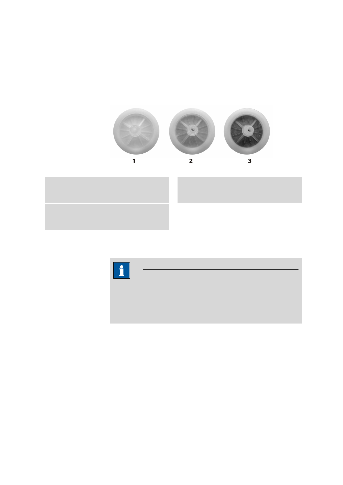
Figure 18 Dust filter - conditions
5 Operation and maintenance
Dust filter new
1
New dust filters are white on the intake side.
Dust filter full
3
Full dust filters have a dark to black color on
the intake side and must be exchanged.
Dust filter used
2
Used dust filters are discolored on the intake
side.
5.3 Regenerating or replacing the molecular sieve
NOTE
Regenerate the molecular sieve regularly.
The intervals at which you have to regenerate the molecular sieve
depends on the humidity in the laboratory and also on the frequency
of use of the instrument.
The molecular sieve filled in the drying flask (2-9) serves to adsorb disruptive oxidizing gases as well as of the water from the aspirated air.
892 Professional Rancimat
You can regenerate the molecular sieve in the drying oven at
approx. +140 - +180 °C for 24 to 48 h. You can order a new molecular
sieve under the order number 6.2811.000.
■■■■■■■■
41
Page 50

5.4 Quality management and qualification with Metrohm
CAUTION
Do not fill the hot molecular sieve directly into the drying flask after
regeneration, as otherwise the plastic filter on the filter tube will melt.
Wait until the molecular sieve has cooled down before filling.
■■■■■■■■■■■■■■■■■■■■■■
5.4 Quality management and qualification with
Metrohm
Quality management
Metrohm offers you comprehensive support in implementing quality management measures for instruments and software.
Qualification
Please contact your local Metrohm representative for support in qualification of instruments and software. The Installation Qualification (IQ)
and Operational Qualification (OQ) are offered by Metrohm representatives as a service. They are carried out by trained employees using standardized qualification documents and in accordance with the currently
applicable requirements of the regulated industry.
Maintenance
The electronic and mechanical functional groups of Metrohm instruments
can and should be checked by specialist personnel from Metrohm as part
of a regular preventive maintenance schedule. Please ask your local
Metrohm representative regarding the precise terms and conditions
involved in concluding a corresponding maintenance agreement.
For detailed information on this topic, please visit www.metrohm.com.
■■■■■■■■
42
892 Professional Rancimat
Page 51

■■■■■■■■■■■■■■■■■■■■■■
6 Troubleshooting
6.1 Problems
Problem Cause Remedy
6 Troubleshooting
The pump is louder
than normal.
No air flow can be
detected in the reaction vessel (it does
not bubble),
although the pump
is running.
The air flow is blocked
somewhere before or after
the pump.
■ Check dust filter and replace it if necessary.
■ Check filter tube on the drying flask cap for
blockages and, if necessary, gently tap on
it to remove them.
Extra air is aspirated from
elsewhere other than the
dust filter. There is a leak
somewhere in the system
■ Check the FEP tubing for cracks, kinks, etc.
and fasten it tightly. Replace it if necessary.
■ Place the drying flask cap correctly on the
drying flask and screw tight.
before the pump.
The air supply is blocked. ■ Remove the FEP tubing from the thread
adapter. Here, a slight air flow must be
perceptible. If this is not the case, please
contact Metrohm Service.
■ Check FEP tubing for blockages. If neces-
sary, clean or replace.
■ Check the thread adapter and the air tube
on the reaction vessel cover for blockages.
If necessary, clean or replace.
The FEP tubing for the air
supply is defective.
Check the FEP tubing for cracks, kinks etc. If
necessary, replace.
No air flow can be
detected in the measuring vessel (it does
not bubble),
although an air flow
can be discerned in
the reaction vessel.
892 Professional Rancimat
The FEP tubing for the air
Tighten the FEP tubing on both sides.
supply is not connected
correctly.
The air tube does not
immerse in the sample.
■ Press the reaction vessel cover all the way
down.
■ Use more sample.
The connection is blocked. ■ Check the tubing connector on the reac-
tion vessel cover for blockage and, if necessary, clean.
■ Check the silicone tubing for blockage and,
if necessary, clean.
■ Check the tubing adapter and the PTFE
cannula on the measuring vessel cover for
blockage and, if necessary, clean.
■■■■■■■■
43
Page 52

6.1 Problems
Problem Cause Remedy
The connection is leaking. Check the silicone tubing for leakages and, if
necessary, replace.
■■■■■■■■■■■■■■■■■■■■■■
The induction times
are not reproducible
for multiple determinations.
The reaction vessel cover
does not sit correctly or
tightly enough.
The connection is wrongly
connected.
The reaction vessels used
are not clean.
■ If the reaction vessel cover is oblique or not
completely mounted, press it all the way
down.
■ If the reaction vessel cover is loose on the
reaction vessel despite correct assembly,
the cover has to be replaced.
■ Make sure that the PTFE cannula for air
supply is connected to the In opening of
the measuring vessel cover.
■ Make sure that the silicone tubing is con-
nected to the tubing adapter that is mounted on the In opening.
■ Make sure that the reaction vessel is con-
nected to the measuring vessel that
belongs to the corresponding measuring
position.
■ Clean the reaction vessels of particles (dust,
cardboard, etc.) with nitrogen before
weighing in the sample.
■ Only use new, unused reaction vessels.
The reaction vessels used
are scratched on the
inside.
The reaction vessel cover
does not sit correctly or
tightly enough.
The connection to the
measuring vessel is not
mounted correctly.
Only use new, unused reaction vessels.
■ If the reaction vessel cover is oblique or not
completely mounted, press it all the way
down.
■ If the reaction vessel cover is loose on the
reaction vessel despite correct assembly,
the cover has to be replaced.
Ensure that no air can escape through leaks
when transferring from the reaction vessel to
the measuring vessel.
■■■■■■■■
44
892 Professional Rancimat
Page 53

■■■■■■■■■■■■■■■■■■■■■■
Problem Cause Remedy
6 Troubleshooting
The stability times
are not reproducible
for multiple determinations.
The temperature in different positions of a heating
block differs, as sample has
burnt on at one or more
places in the recess of the
heating block.
The sample is not homogenous.
The cell constant was not
determined or does not
correspond to the value
entered.
The conductivity measuring
cell is contaminated.
See also: The induction
times are not reproducible
for multiple determinations.
If necessary, carefully remove contamination
from the cold heating block.
Homogenize the sample.
■ Determine the cell constant.
■ Make sure that the assignment of the con-
ductivity sensors is correct, so that the
determined cell constant actually corresponds to the measuring cell used.
■ Make sure that the measuring cell is not
contaminated. Clean if necessary.
Check the measuring cell and, if necessary,
clean.
The induction time
is longer/shorter
than expected.
The stability time is
longer/shorter than
expected.
The temperature is not
selected correctly.
See also: The induction
times are not reproducible
for multiple determinations.
The conductivity change is
not correctly defined.
See also: The stability times
are not reproducible for
multiple determinations.
See also: The induction
time is longer/shorter than
expected.
■ Make sure that the correct method for the
determination has been selected.
■ Check whether the Sample temperature
and the Temperature correction are
indicated correctly in the method.
Make sure that the value defined for the conductivity change in the method is correct.
892 Professional Rancimat
■■■■■■■■
45
Page 54

6.1 Problems
Problem Cause Remedy
■■■■■■■■■■■■■■■■■■■■■■
The measurement
curves are extremely
noisy.
The air supply for the measuring solution is directed
to the conductivity measuring cell.
Gas bubbles adhere to the
conductivity measuring cell
during measurement.
During the measurement,
sample evaporates in the
reaction vessel and condenses in the measuring
vessel. This results in contamination of the conductivity measuring cell, which
in turn promotes adherence of gas bubbles.
Loosen the tubing adapter on the measuring
vessel cover and turn the PTFE cannula such
that the air is no longer directed to the electrode and fix it in this position.
■ Make sure that the measuring cell is clean
and free of fat. If necessary, clean thoroughly.
■ In some cases, ultrapure water contains a
large proportion of dissolved air. In this
case, degas the ultrapure water before the
measurement for 5 to 10 min in a vacuum.
■ Keep the measuring time as short as possi-
ble, by about 4 to 6 h. The induction time
can be reduced by about half by increasing
the temperature by 10 °C.
■ Reduce the temperature to such an extent
that sample evaporation is minimized or
eliminated. However, this can substantially
extend the measuring time. The induction
time approximately doubles by reducing
the temperature by 10 °C.
■ Use an oil separator (6.2753.200).
The curve shows a
step which means
that the induction
time is no longer
determined correctly.
Side reactions occur at the
start or during the measurement. These reactions
cause the conductivity in
the measuring cell to rise.
■ Use the Evaluation suppression in the
method.
■ In addition to Endpoint(s) activate also
Conductivity (e.g. 200 µS/cm) as stop cri-
terion in the method and select the Stop
once all the criteria have been fulfilled
option. The evaluation parameters can be
optimized on the basis of this curve, or the
curve can be evaluated manually.
■ Increase the Evaluation sensitivity
method parameter.
■■■■■■■■
46
892 Professional Rancimat
Page 55

■■■■■■■■■■■■■■■■■■■■■■
Problem Cause Remedy
6 Troubleshooting
The curve shows a
step at the start of
the measurement,
which has not occurred in previous
measurements.
The induction time
is not evaluated
automatically,
although a significant break point can
be noticed in the
curve.
The reaction vessel cover
and/or the tubing still contain residues from previous
measurements. These residues are then transferred
to the measuring vessel
with the flow of warm air
during a new measurement.
The Evaluate induction
time option is deactivated
in the method.
The Evaluation suppres-
sion option preventing the
evaluation of the curve in
the corresponding time
period is defined in the
method.
Automatic detection of the
induction time is not yet
possible.
■ Thoroughly clean the reaction vessel cover
and the silicone tubing.
■ Replace the reaction vessel cover and the
silicone tubing from time to time.
■ If an oil separator has been used, thor-
oughly clean it.
Activate the evaluation of the induction time in
the method.
Deactivate the corresponding option in the
method.
Keep the determination running until the
induction time is automatically found.
The measurement
aborts without an
endpoint being
found.
The curve progression is
too flat, with the result
that automatic detection
of the induction time is not
possible.
An inappropriately high
value was used in the
method for the Evalua-
tion sensitivity. This value
makes a curve evaluation
impossible.
The measurement has been
stopped manually.
A time or conductivity
defined as a stop criterion
in the method is reached
before the endpoint.
■ Reduce the Evaluation sensitivity
method parameter.
■ Evaluate the curves manually using tan-
gents.
Enter a lower value (e.g. 1.0) for the Evalua-
tion sensitivity option in the method.
Keep the measurement running until the endpoint is automatically found.
■ Activate the Stop once all the criteria
have been fulfilled option in the method.
■ Increase the value for time or conductivity.
■ Deactivate time or conductivity as stop cri-
terion.
892 Professional Rancimat
■■■■■■■■
47
Page 56

7.1 General data
7 Technical specifications
7.1 General data
■■■■■■■■■■■■■■■■■■■■■■
Number of instruments that can be
connected
Number of samples per instrument
Sample amount Several grams / several milliliters
1 - 4
1 - 8 (4 each per heating block)
7.2 Temperature control and measurement
Sample temperature setting range
Temperature correction
Temperature measuring range
Resolution 0.1 °C
50 - 220 °C
±0 - 9.9 °C
(Can be entered manually or determined automatically using the external temperature sensor.)
0 - 300 °C
Maximum deviation of the heating
block temperature
from the set value
(50 - 220 °C)
Reproducibility of
the set temperature
Maximum temperature difference
between different
measuring positions per block
Temperature fluctuations
±0.3 °C
typ. ±0.2 °C
typ. < 0.3 °C
typ. < 0.1 °C
(With operating temperature attained, reaction vessels inserted and
identically filled and 20 L/h air throughput.)
■■■■■■■■
48
892 Professional Rancimat
Page 57

■■■■■■■■■■■■■■■■■■■■■■
7 Technical specifications
Shutdown temperature
Heating time for
the instrument
External temperature of the instrument
260 ± 15 °C
(Resetting and troubleshooting carried out by Metrohm Service.)
approx. 45 min (from 20 °C to 120 °C)
approx. 60 min (from 20 °C to 220 °C)
< 50 °C
(at operating temperature 220 °C)
7.3 External temperature sensor
Sensor
4-pin for sensor Pt100 (6.1111.010)
7.4 Conductivity measurement
Sensor
Electrode Conductivity measuring cell with 2 stainless steel electrodes
Measuring principle
Conductivity measuring cell, integrated in the measuring vessel cover
(6.0913.130)
AC current measurement with 1 kHz frequency and approx. 1.0 V
amplitude (peak to peak)
Cell constant 1.0 - 1.2
(The exact value can be entered manually or determined automatically.)
Measuring range 0 - 400 µS/cm (at c = 1)
Resolution 0.1 µS/cm
Display range 0 - 999 µS/cm
Maximum deviation from measured value
±(0.5 µS/cm + 1% of the measured value)
892 Professional Rancimat
■■■■■■■■
49
Page 58

7.5 Gas flow regulation
7.5 Gas flow regulation
Pump Membrane pump (brushless motor)
■■■■■■■■■■■■■■■■■■■■■■
Volumetric flow
range
Maximum deviation from the set
range
1 - 25 L/h at 25 °C and 1,013 mbar
±(0.25 L/h + 5% of the measured value)
7.6 USB interface
USB connector
USB plug type B
7.7 Power socket
Nominal voltage
range
Frequency 50 and 60 Hz (autosensing)
Power consumption
Fuse Diameter 5 mm, length 20 mm
100 - 120 V and 220 - 240 V ± 10% (autosensing)
450 VA
4.0 ATH (slow-acting)
max
7.8 Safety specifications
This instrument fulfills the following electrical safety requirements:
CE marking in accordance with the EU directives:
■ 2006/95/EC (Low Voltage Directive, LVD)
■ 2004/108/EC (EMC Directive, EMC)
Design and testing According to EN/IEC/UL 61010-1, CSA-C22.2 No. 61010-1 protection
class I, EN/IEC 61010-2-010, EN/IEC 60529, degree of protection IP20.
Safety instructions This document contains safety instructions which have to be followed
by the user in order to ensure safe operation of the instrument.
■■■■■■■■
50
892 Professional Rancimat
Page 59

■■■■■■■■■■■■■■■■■■■■■■
7.9 Electromagnetic compatibility (EMC)
Emission Standards fulfilled:
■ EN/IEC 61326-1
■ EN/IEC 61000-6-3
■ EN 55011 / CISPR 11
■ EN/IEC 61000-3-2
■ EN/IEC 61000-3-3
Immunity Standards fulfilled:
■ EN/IEC 61326-1
■ EN/IEC 61000-6-2
■ EN/IEC 61000-4-2
■ EN/IEC 61000-4-3
■ EN/IEC 61000-4-4
■ EN/IEC 61000-4-5
■ EN/IEC 61000-4-6
■ EN/IEC 61000-4-11
■ EN/IEC 61000-4-14
■ EN/IEC 61000-4-28
7 Technical specifications
7.10 Ambient temperature
Nominal function
range
Storage –20 - +70 °C
Transport –40 - +70 °C
+5 - +45 °C
(at 20 - 80% humidity)
7.11 Dimensions/Material
Width
Height 277 mm (without accessories)
Depth 462 mm
Weight 16.1 kg (without accessories)
Cover material Baydur®110 FR-6 with flame retardation for fire class UL94VO, CFC-
Base material Steel sheet, coated
383 mm
free
892 Professional Rancimat
■■■■■■■■
51
Page 60

8.1 Quality Management Principles
8 Conformity and warranty
8.1 Quality Management Principles
Metrohm Ltd. holds the ISO 9001:2000 Certificate, registration number
10872-02, issued by SQS (Swiss Association for Quality and Management
Systems). Internal and external audits are carried out periodically to assure
that the standards defined by Metrohm’s QM Manual are maintained.
The steps involved in the design, manufacture and servicing of instruments
are fully documented and the resulting reports are archived for ten years.
The development of software for PCs and instruments is also duly documented and the documents and source codes are archived. Both remain
the possession of Metrohm. A non-disclosure agreement may be asked to
be provided by those requiring access to them.
The implementation of the ISO 9001:2000 quality management system is
described in Metrohm’s QM Manual, which comprises detailed instructions on the following fields of activity:
■■■■■■■■■■■■■■■■■■■■■■
Instrument development
The organization of the instrument design, its planning and the intermediate controls are fully documented and traceable. Laboratory testing
accompanies all phases of instrument development.
Software development
Software development occurs in terms of the software life cycle. Tests are
performed to detect programming errors and to assess the program’s
functionality in a laboratory environment.
Components
All components used in the Metrohm instruments have to satisfy the quality standards that are defined and implemented for our products. Suppliers of components are audited by Metrohm as the need arises.
Manufacture
The measures put into practice in the production of our instruments guarantee a constant quality standard. Production planning and manufacturing
procedures, maintenance of production means and testing of components, intermediate and finished products are prescribed.
Customer support and service
Customer support involves all phases of instrument acquisition and use by
the customer, i.e. consulting to define the adequate equipment for the
analytical problem at hand, delivery of the equipment, user manuals, train-
■■■■■■■■
52
892 Professional Rancimat
Page 61

■■■■■■■■■■■■■■■■■■■■■■
ing, after-sales service and processing of customer complaints. The
Metrohm service organization is equipped to support customers in implementing standards such as GLP, GMP, ISO 900X, in performing Operational Qualification and Performance Verification of the system components or in carrying out the System Validation for the quantitative determination of a substance in a given matrix.
8.2 Warranty (guarantee)
Metrohm guarantees that the deliveries and services it provides are free of
defects in materials, design or manufacturing.
The general warranty period is 36 months (exclusions below) from the
date of delivery, or 18 months in the event of continuous operation. The
warranty remains valid on the condition that the servicing is provided by a
service organization authorized by Metrohm at defined intervals and with
a defined scope.
The warranty period for anion suppressors of the type "MSM" is 120
months from the date of delivery or 60 months in the case of continuous
operation.
8 Conformity and warranty
The warranty period for IC separation columns is 90 days after start-up.
For third-party components that are recognizable as such, the manufacturer's warranty regulations apply.
For instruments sold under the Metrohm NIRSystems brand, a full 16month warranty is applicable. In the event of continuous operation, the
warranty period is reduced by half.
Consumables and materials with limited storage life and glass breakage in
the case of electrodes or other glass parts are excluded from the warranty.
Warranty claims cannot be asserted if the ordering party has failed to
meet its payment obligations according to schedule.
During the warranty period, Metrohm undertakes either to replace free of
charge or to credit the purchaser for any modules or components that can
be shown to be faulty. Any transport or customs fees that may apply are
the responsibility of the ordering party.
The precondition for this is that the ordering party has to specify the article number, the article designation, an adequate error description, the
delivery date and (if applicable) the serial number or chip data in the Support Tracker. Metrohm then decides whether a replacement or a credit
note is to be issued or whether the faulty part has to be returned using
the Return Material Authorization (RMA). If a replacement or credit note is
issued, the ordering party undertakes to store the faulty part for at least
24 months in accordance with the current storage directives (in compliance with ESD guidelines) and to hold it in readiness for onsite inspection
892 Professional Rancimat
■■■■■■■■
53
Page 62

8.2 Warranty (guarantee)
■■■■■■■■■■■■■■■■■■■■■■
or for return shipment to Metrohm. Metrohm reserves the right to invoice
the ordering party for these articles, including retroactively, in the event of
noncompliance with these preconditions.
The same warranty periods that are specified for a corresponding new
part apply to parts that are replaced or repaired within the above-mentioned warranty periods. However, replacement or repair of a part does
not extend the warranty period of the entire system.
Deficiencies arising from circumstances that are not the responsibility of
Metrohm, such as improper storage or improper use, etc., are expressly
excluded from the warranty.
Metrohm also offers a 120-month spare parts availability guarantee and a
60-month PC software support warranty, calculated from the date on
which the product is withdrawn from the market. The content of this warranty is the ability of the customer to obtain functioning spare parts or
appropriate software support at market prices during the time of the warranty period. This does not apply for software products sold under the
Metrohm NIRSystems brand.
If Metrohm AG is unable to meet this obligation due to circumstances
beyond the control of Metrohm AG, then the ordering party shall be
offered alternative solutions at preferential conditions.
■■■■■■■■
54
892 Professional Rancimat
Page 63

■■■■■■■■■■■■■■■■■■■■■■
9 Accessories
Up-to-date information on the scope of delivery and optional accessories
for your instrument can be found on the Internet.
When you receive your new instrument, we recommend downloading
the accessories list from the Internet, printing it out and keeping it
together with the manual for reference purposes.
Instruments currently sold
If you do not know the article number of your instrument, proceed as follows:
Downloading the accessories list
9 Accessories
NOTE
Go to the Metrohm website http://www.metrohm.com/com.
1
2
Click on .
The Search webpage will be displayed.
Enter a search term relating to the instrument into the search field
3
and click on Find.
The search results will be displayed.
In the search results, select the Devices tab (if it is not already
4
selected) and then click on the Metrohm article number of the
required instrument (e.g. 2.852.0050).
The page with information pertaining to the searched article is displayed.
Select the Parts tab.
5
The complete list of accessories with the scope of delivery and the
optional accessories will be displayed.
6
Click on .
892 Professional Rancimat
■■■■■■■■
55
Page 64

■■■■■■■■■■■■■■■■■■■■■■
The Partslists webpage will be displayed.
Select the desired output language.
7
With the article number entered, click on the command Generate
8
PDF.
The PDF file with the accessories data will be created in the language
selected.
Direct access for all instruments
If you are unable to find your instrument using the search as described
above, this may be due to the instrument not being sold anymore. Using
the article number, you can download accessories lists for all instruments
as follows:
Downloading the accessories list
Type http://partslists.metrohm.com into your Internet browser.
1
The Partslists webpage will be displayed.
Select the desired output language.
2
Enter the article number and click on the Generate PDF command.
3
The PDF file with the accessories data will be created in the language
selected.
■■■■■■■■
56
892 Professional Rancimat
Page 65

■■■■■■■■■■■■■■■■■■■■■■
Index
Index
A
Accessories
Mount ................................ 11
Air purification
Mount accessories .............. 11
Assemble
Oil separator ....................... 39
Autoxidation ............................ 25
C
Cell constant
Determine .......................... 26
Clean
Accessories ......................... 37
Measuring vessel ................ 37
Oil separator ....................... 39
Reaction vessel ................... 37
Tubing ................................ 38
Computer
Connect ............................. 23
Conductivity measurement
Measuring range ................ 49
Resolution .......................... 49
D
Determination
Prepare ............................... 35
Disassemble
Accessories ......................... 38
Oil separator ....................... 38
Drying flask
Mount ................................ 12
Dust filter
Mount ................................ 11
Replace .............................. 41
E
Electrostatic charge .................... 4
Emulsion fat ............................. 30
External air supply
Mount accessories .............. 13
External temperature ................ 49
F
Fat
Emulsion fats ...................... 30
Non-liquid, pure fats ........... 30
Fuse
Replace .............................. 21
G
Gas flow
Range ................................. 50
Guarantee ................................ 53
H
Heater
Range ................................. 48
Start manually .................... 36
Switch off ........................... 36
Heating period ......................... 36
Heating time ............................ 49
I
Induction time .......................... 25
Installation qualification ............ 42
Internal air supply
Mount accessories .............. 11
M
Mains voltage ............................. 4
Maintenance agreement .......... 42
Measuring vessel
Assemble ............................ 14
Molecular sieve
Regenerate ................... 13, 41
O
Oil
Pure, clear oils .................... 30
Oil/fat
Samples containing oil and fat
........................................... 30
Operational qualification .......... 42
P
Prepare sample
Non-liquid, pure fats ........... 30
Pure, clear oils .................... 30
Samples containing oil and fat
........................................... 31
Prepare the sample
Emulsion fats ...................... 33
Q
Quality management ................ 42
R
Reaction vessel
Assemble ............................ 14
S
Safety instructions ...................... 3
Sample
Prepare ............................... 30
Sample identification
Enter .................................. 36
Service ....................................... 4
Shutdown temperature ............ 49
Solid samples ............................ 30
Stability time .............................. 1
Switch on ................................. 22
T
Temperature correction
Determine .......................... 27
Temperature measurement
Measuring range ................ 48
Reproducibility .................... 48
Resolution .......................... 48
W
Warranty .................................. 53
892 Professional Rancimat
■■■■■■■■
57
 Loading...