

Page 1
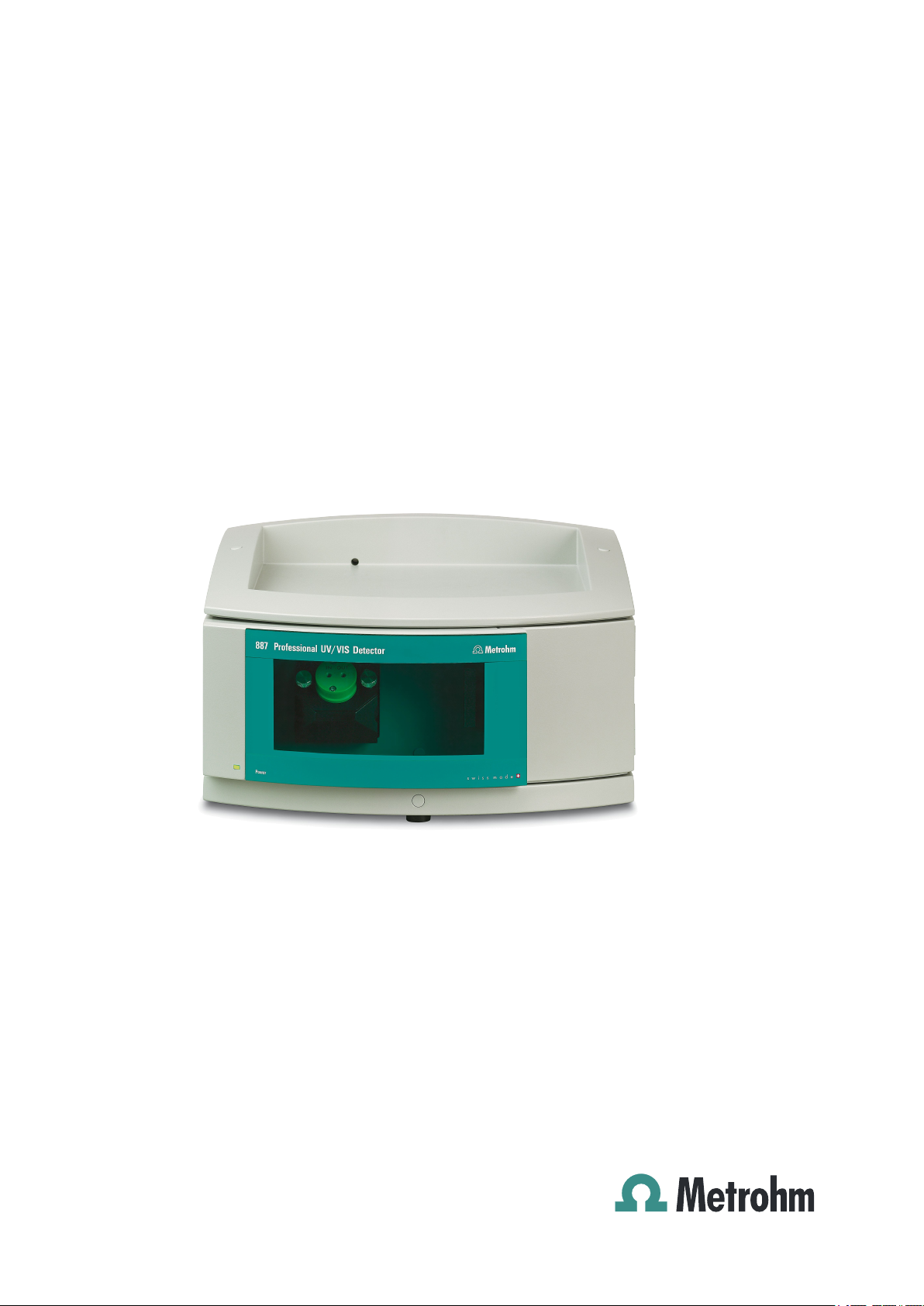
887 Professional UV/VIS Detector
2.887.0010
Manual
8.887.8003EN
Page 2

Page 3

Metrohm AG
CH-9100 Herisau
Switzerland
Phone +41 71 353 85 85
Fax +41 71 353 89 01
info@metrohm.com
www.metrohm.com
887 Professional UV/VIS Detector
2.887.0010
Manual
8.887.8003EN 07.2011 zst
Page 4

Teachware
Metrohm AG
CH-9100 Herisau
teachware@metrohm.com
This documentation is protected by copyright. All rights reserved.
Although all the information given in this documentation has been
checked with great care, errors cannot be entirely excluded. Should you
notice any mistakes please send us your comments using the address
given above.
Documentation in additional languages can be found on
http://products.metrohm.com under Literature/Technical documenta-
tion.
Page 5

■■■■■■■■■■■■■■■■■■■■■■
Table of contents
1 Introduction 1
1.1 Instrument description ......................................................... 1
1.2 Intended use ......................................................................... 1
1.3 About the documentation ................................................... 2
1.3.1 Modifications since previous version ........................................ 2
1.3.2 Symbols and conventions ........................................................ 2
1.4 Safety instructions ................................................................ 3
1.4.1 General notes on safety ........................................................... 3
1.4.2 Electrical safety ........................................................................ 3
1.4.3 Tubing and capillary connections ............................................. 4
1.4.4 Flammable solvents and chemicals ........................................... 4
1.4.5 Recycling and disposal ............................................................. 5
2 Overview of the instrument 6
Table of contents
2.1 Front ...................................................................................... 6
2.2 Rear ........................................................................................ 6
3 Installation 8
3.1 Setting up the instrument .................................................... 8
3.1.1 Packaging ................................................................................ 8
3.1.2 Checks .................................................................................... 8
3.1.3 Location .................................................................................. 8
3.2 Proposed setup ..................................................................... 8
3.3 Mounting base tray and bottle holder (optional) ............ 10
3.3.1 Removing / mounting the base tray ....................................... 10
3.3.2 Removing / mounting the bottle holder ................................. 12
3.4 Capillary connections in the IC system ............................. 15
3.5 Installing the flow-through cell ......................................... 17
3.6 Connecting the flow-through cell ..................................... 19
3.7 Connecting the instrument ................................................ 20
3.7.1 Connecting the instrument to the PC ..................................... 20
3.7.2 Connecting the instrument to mains supply ........................... 20
4 Start-up 22
5 Operation 24
887 Professional UV/VIS Detector
■■■■■■■■
III
Page 6

Table of contents
■■■■■■■■■■■■■■■■■■■■■■
6 Handling and maintenance 25
6.1 General notes ...................................................................... 25
6.1.1 Care ...................................................................................... 25
6.1.2 Maintenance by Metrohm Service .......................................... 25
6.1.3 Operation .............................................................................. 25
6.1.4 Shutting down ...................................................................... 26
6.2 Door ..................................................................................... 26
6.3 Replacing the UV lamp ....................................................... 27
6.4 Replacing the VIS Lamp ..................................................... 30
6.5 Adjusting the lamp settings .............................................. 30
6.6 Cleaning the flow-through cell .......................................... 31
6.7 Quality Management and validation with Metrohm ....... 35
7 Troubleshooting 36
7.1 Problems and their solutions ............................................. 36
8 Technical specifications 37
8.1 Reference conditions .......................................................... 37
8.2 UV/VIS detector .................................................................. 37
8.3 Lamps .................................................................................. 38
8.4 Ambient conditions ............................................................ 39
8.5 Housing ............................................................................... 39
8.6 Mains connection ............................................................... 40
8.7 Safety specification ............................................................ 40
8.8 Electromagnetic compatibility (EMC) ................................ 40
9 Conformity and warranty 41
9.1 Declaration of Conformity ................................................. 41
9.2 Quality Management Principles ........................................ 42
9.3 Warranty (guarantee) ......................................................... 43
10 Accessories 44
10.1 Scope of delivery ................................................................ 44
■■■■■■■■
IV
10.2 Optional accessories ........................................................... 46
Index 49
887 Professional UV/VIS Detector
Page 7

■■■■■■■■■■■■■■■■■■■■■■
Table of figures
Figure 1 Front ................................................................................................. 6
Figure 2 Rear .................................................................................................. 6
Figure 3 Proposed setup ................................................................................. 9
Figure 4 Connection of capillaries with pressure screws ................................ 15
Figure 5 Cell block ........................................................................................ 17
Figure 6 Connecting detector input ............................................................... 19
Figure 7 Connecting detector output ............................................................ 20
Figure 8 Intensity spectrum ok ...................................................................... 23
Figure 9 Intensity spectrum too high ............................................................. 23
Figure 10 Operating hours counter ................................................................. 27
Figure 11 Lamp module .................................................................................. 27
Figure 12 Lamp module – without UV lamp .................................................... 29
Figure 13 Flow-through cell – parts ................................................................. 33
Table of figures
887 Professional UV/VIS Detector
■■■■■■■■
V
Page 8

Page 9

■■■■■■■■■■■■■■■■■■■■■■
1 Introduction
1.1 Instrument description
The 887 Professional UV/VIS Detector is within the 850 Professional
IC family an independent instrument for the photometric determination of
light absorbing substances in the UV/VIS range.
It can be used as an alternative UV/VIS detector with any instrument of
the 850 Professional IC, the 881 Compact IC pro, and the 882 Compact IC
plus families.
The 887 Professional UV/VIS Detector is operated with MagIC Net™
Software. It is connected via a USB connection to a PC on which
MagIC Net™ is installed. The software automatically recognizes the instrument and checks its functional readiness. MagIC Net™ controls and monitors the instrument, evaluates the measured data and administers it in a
database.
1 Introduction
Additional information on operating MagIC Net™ can be found in the
document "Tutorial for MagIC Net™" or in the online help.
1.2 Intended use
The 887 Professional UV/VIS Detector is used as an independent detector
with various analysis instruments of the Metrohm line of instruments.
This instrument is suitable for processing chemicals and flammable samples. The usage of the 887 Professional UV/VIS Detector therefore requires
that the user has basic knowledge and experience in the handling of toxic
and caustic substances. Knowledge with respect to the application of the
fire prevention measures prescribed for laboratories is also mandatory.
887 Professional UV/VIS Detector
■■■■■■■■
1
Page 10
1.3 About the documentation
1.3 About the documentation
Caution
Please read through this documentation carefully before putting the
instrument into operation. The documentation contains information
and warnings which the user must follow in order to ensure safe operation of the instrument.
1.3.1 Modifications since previous version
This manual substitutes its previous version 8.887.8002EN, it includes the
following changes:
■ The conditions for the adjustment of lamp settings are specified more
precisely (see "Evaluating the intensity spectrum", page 22) and (see
Chapter 6.5, page 30).
■ In chapter Replacing the UV lamp, page 27 the pictures were
replaced to show the new lamp module, which allows the use of the
new halogen lamp.
■ Pin assignment of the analog outpot added (see Chapter 8.2, page
37).
■■■■■■■■■■■■■■■■■■■■■■
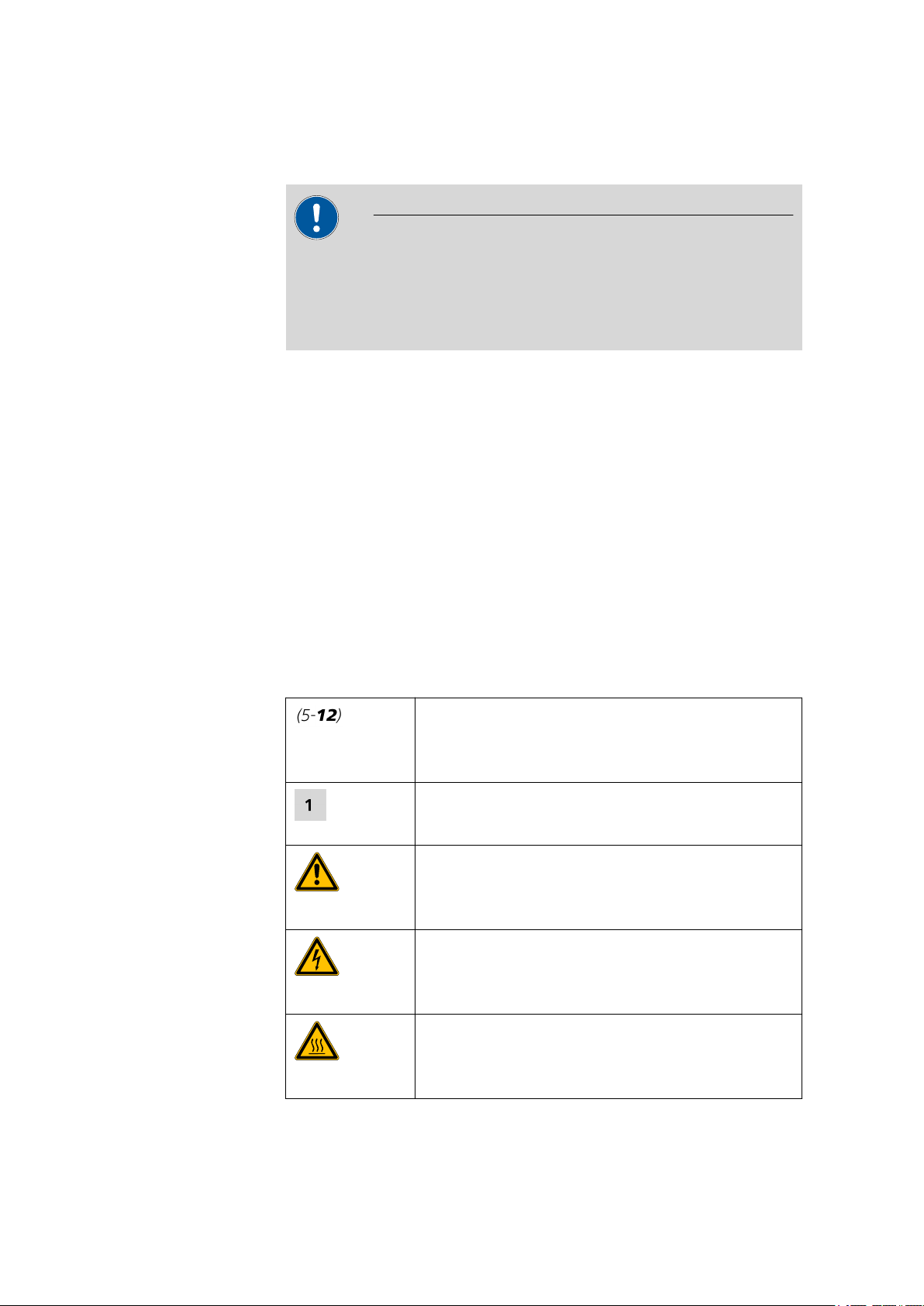
1.3.2 Symbols and conventions
The following symbols and styles are used in this documentation:
Cross-reference to figure legend
The first number refers to the figure number, the
second to the instrument part in the figure.
Instruction step
Carry out these steps in the sequence shown.
Warning
This symbol draws attention to a possible life hazard
or risk of injury.
Warning
This symbol draws attention to a possible hazard due
to electrical current.
Warning
This symbol draws attention to a possible hazard due
to heat or hot instrument parts.
■■■■■■■■
2
887 Professional UV/VIS Detector
Page 11
■■■■■■■■■■■■■■■■■■■■■■
1.4 Safety instructions
1.4.1 General notes on safety
Warning
This instrument may only be operated in accordance with the specifications in this documentation.
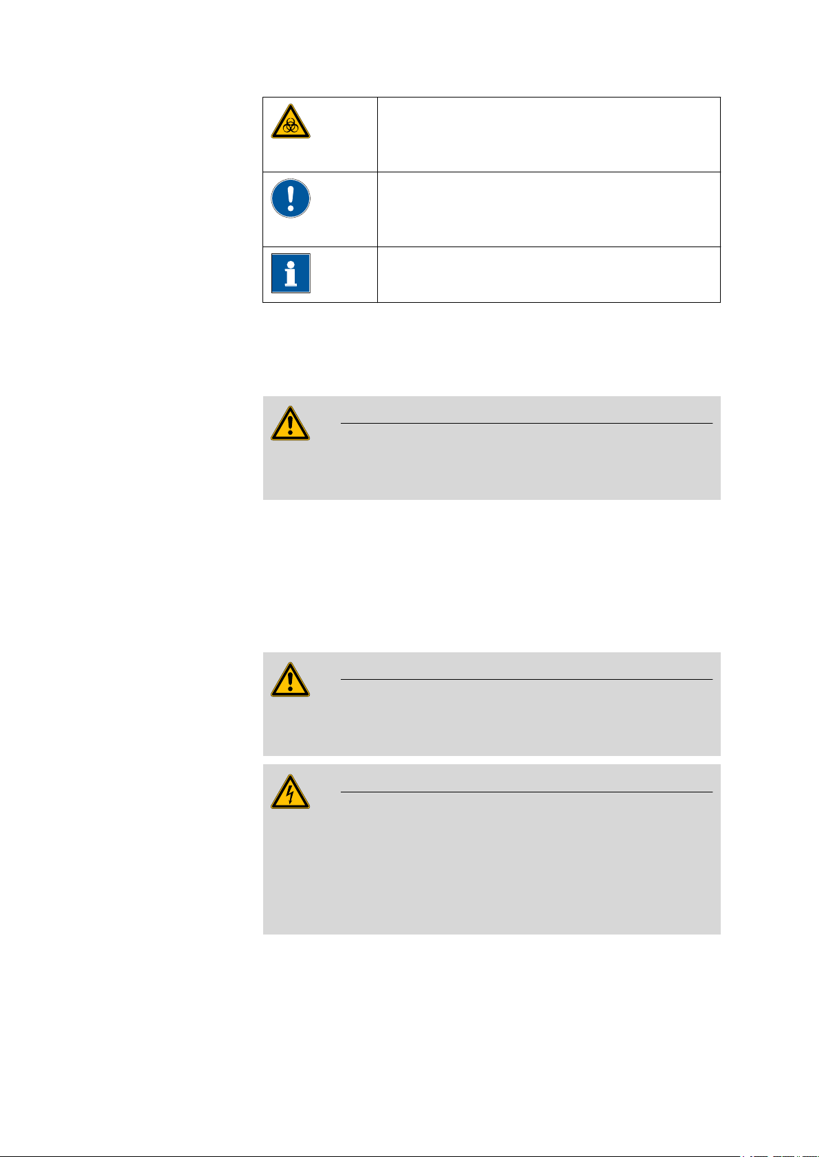
1 Introduction
Warning
This symbol draws attention to a possible biological
hazard.
Caution
This symbol draws attention to a possible damage of
instruments or instrument parts.
Note
This symbol marks additional information and tips.
This instrument has left the factory in a flawless state in terms of technical
safety. To maintain this state and ensure non-hazardous operation of the
instrument, the following instructions must be observed carefully.
1.4.2 Electrical safety
The electrical safety when working with the instrument is ensured as part
of the international standard IEC 61010.
Only personnel qualified by Metrohm are authorized to carry out service
work on electronic components.
Never open the housing of the instrument. The instrument could be
damaged by this. There is also a risk of serious injury if live components
are touched.
There are no parts inside the housing which can be serviced or replaced
by the user.
Warning
Warning
887 Professional UV/VIS Detector
■■■■■■■■
3
Page 12
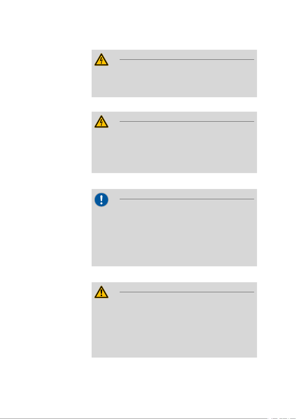
1.4 Safety instructions
■■■■■■■■■■■■■■■■■■■■■■
Mains voltage
Warning
An incorrect mains voltage can damage the instrument.
Only operate this instrument with a mains voltage specified for it (see
rear panel of the instrument).
Protection against electrostatic charges
Warning
Electronic components are sensitive to electrostatic charges and can be
destroyed by discharges.
Always pull the mains cable out of the mains connection socket before
connecting or disconnecting electrical appliances on the rear panel of
the instrument.
1.4.3 Tubing and capillary connections
Caution
Leaks in tubing and capillary connections are a safety risk. Tighten all
connections well by hand. Avoid applying excessive force to tubing
connections. Damaged tubing ends lead to leakage. Appropriate tools
can be used to loosen connections.
Check the connections regularly for leakage. If the instrument is used
mainly in unattended operation, then weekly inspections are mandatory.
1.4.4 Flammable solvents and chemicals
Warning
All relevant safety measures are to be observed when working with
flammable solvents and chemicals.
■ Set up the instrument in a well-ventilated location (e.g. laboratory
flue).
■ Keep all sources of flame far from the workplace.
■ Clean up spilled fluids and solids immediately.
■ Follow the safety instructions of the chemical manufacturer.
■■■■■■■■
4
887 Professional UV/VIS Detector
Page 13

■■■■■■■■■■■■■■■■■■■■■■
1.4.5 Recycling and disposal
This product is covered by European Directive 2002/96/EC, WEEE – Waste
from Electrical and Electronic Equipment.
The correct disposal of your old equipment will help to prevent negative
effects on the environment and public health.
More details about the disposal of your old equipment can be obtained
from your local authorities, from waste disposal companies or from your
local dealer.
1 Introduction
887 Professional UV/VIS Detector
■■■■■■■■
5
Page 14
2.1 Front
1
2
1
8
2
3
9 10
11
12413
5
7
6
2 Overview of the instrument
2.1 Front
■■■■■■■■■■■■■■■■■■■■■■
Figure 1 Front
Detector block
1
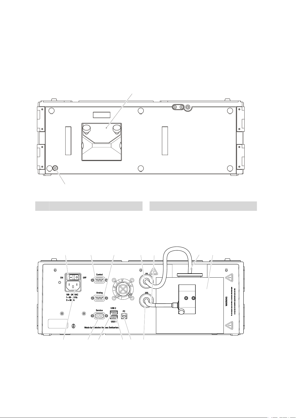
2.2 Rear
Standby indicator
2
Figure 2 Rear
■■■■■■■■
6
887 Professional UV/VIS Detector
Page 15

■■■■■■■■■■■■■■■■■■■■■■
2 Overview of the instrument
Mains switch
1
For switching the instrument on and off.
I = On
O = Off
Analog connection socket
3
Output for analog signals.
VIS lamp connection cable
5
Lamp cooling element
7
Service connection socket
9
Connection for service.
USB 1 connection socket
11
For connecting additional USB instruments.
VIS connection socket
13
For connecting the cable of the VIS lamp.
Control connection socket
2
Not Used.
UV connection socket
4
For connecting the cable of the UV lamp.
UV lamp connection cable
6
Mains connection socket
8
For connecting the mains cable.
USB 2 connection socket
10
For connecting additional USB instruments.
PC connection socket
12
For connecting the USB cable to the PC.
887 Professional UV/VIS Detector
■■■■■■■■
7
Page 16

3.1 Setting up the instrument
3 Installation
3.1 Setting up the instrument
3.1.1 Packaging
The instrument is supplied in highly protective special packaging together
with the separately packed accessories. Keep this packaging, as only this
ensures safe transportation of the instrument.
3.1.2 Checks
Immediately after receipt, check whether the shipment has arrived complete and without damage by comparing it with the delivery note.
3.1.3 Location
The instrument has been developed for operation indoors and may not be
used in explosive environments.
■■■■■■■■■■■■■■■■■■■■■■
Place the instrument in a location of the laboratory which is suitable for
operation, free of vibrations, protected from corrosive atmosphere, and
contamination by chemicals.
The instrument should be protected against excessive temperature fluctuations and direct sunlight.
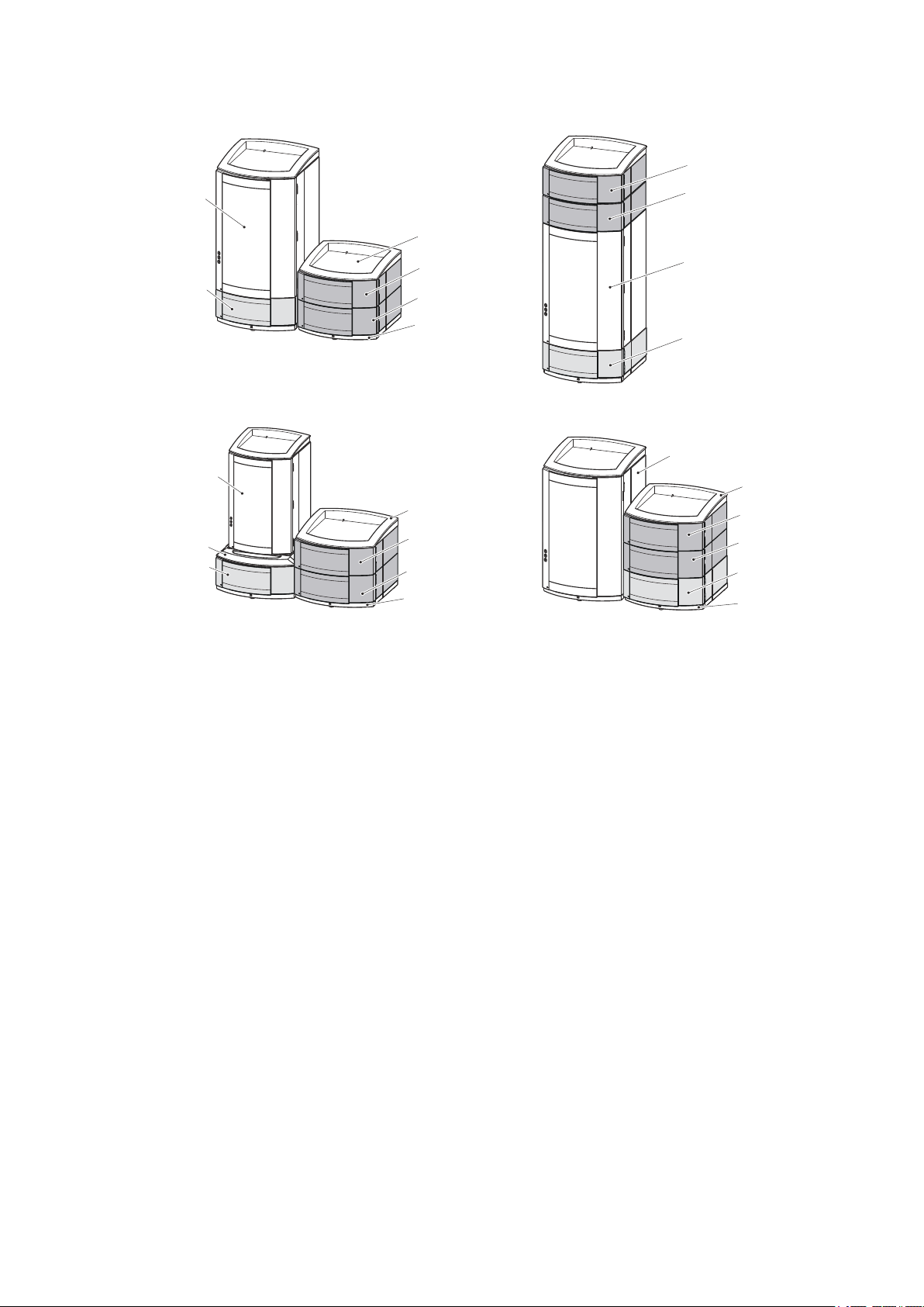
3.2 Proposed setup
The 887 Professional UV/VIS Detector can be used as a detector with the
instruments of the 850 Professional IC, the 881 Compact IC pro, and the
882 Compact IC plus family. For many applications with photometric
detection, a post column reaction with the 886 Professional Thermostat /
Reactor (2.886.0110) is required. To build such a system, you will need a
887 Professional UV/VIS Detector and the following instruments:
■ any 850 Professional IC instrument, or
any 881 Compact IC pro instrument, or
882 Compact IC plus
■ the 886 Professional Thermostat / Reactor
■ optionally: a 872 Extension Module for sample preparation
■ optionally, if the PCR reagent is pumped with a high pressure pump: a
Metrosep BP 1 Guard/2.0 (6.1015.100) backpressure column.
■■■■■■■■
8
An IC system with photometric detection and post column reaction can
be set up in in various combinations (see Figure 3, page 9).
887 Professional UV/VIS Detector
Page 17
■■■■■■■■■■■■■■■■■■■■■■
2.887.0010
2.886.0110
2.850.xxxx
2.872.xxxx
2.850.xxxx
2.872.xxxx
2.887.0010
2.886.0110
6.2061.100
6.2061.110
2.850.xxxx
2.881.xxxx
2.882.xxxx
2.887.0010
2.886.0110
2.872.xxxx
6.2061.110
6.2061.100
2.881.xxx
2.882.xxx
6.2061.120
2.872.xxxx
6.2061.100
2.887.0010
2.886.0110
6.2061.110
3 Installation
887 Professional UV/VIS Detector
Figure 3 Proposed setup
Note for proposed setup
If you want to place the instruments in two stacks, we recommend you
protect the instruments of the second stack and also order the following
accessories:
■ 6.2061.100 Bottle holder (ProfIC)
■ 6.2061.110 Base tray with sensor for Professional IC systems
If you want to stack a 881 Compact IC pro or an 882 Compact IC plus
instrument with a 887 Professional UV/VIS Detector, the 886 Professional
Thermostat / Reactor and/or a 872 Extension Module, you will require the
6.2061.120 System Connector to adapt the different support surfaces.
■■■■■■■■
9
Page 18

3.3 Mounting base tray and bottle holder (optional)
■■■■■■■■■■■■■■■■■■■■■■
3.3 Mounting base tray and bottle holder (optional)
The 6.2061.110 base tray and 6.2061.100 bottle holder protect IC instruments from dust, dirt and leaking fluids. If more than one instrument of
the Professional IC family is used, these can be set up in one or more
stacks. We recommend that a bottle holder and a base tray be mounted
on/below each stack of instruments.
Bottle holder and base tray must be removed or mounted every time one
of the following instruments is mounted on or under an 850 Professional
IC instrument:
■ One or more 872 Extension Module.
■ An 886 Professional Thermostat / Reactor.
■ An 887 Professional UV/VIS Detector.
■ or another instrument of the same support surface.
3.3.1 Removing / mounting the base tray
The base tray must be removed, in case you want to place another instrument under the IC instrument. Proceed as follows:
■■■■■■■■
10
887 Professional UV/VIS Detector
Page 19

■■■■■■■■■■■■■■■■■■■■■■
1
2
3
3 Installation
Removing the base tray
Before you can remove the base tray, the following preconditions must be
met:
■ The instrument is switched off.
■ The bottle holder is cleared.
■ All connections at the rear of the instrument are disconnected.
■ There are no loose parts in the instrument.
To remove the base tray, you need the 6.2621.100 hexagon key 3 mm.
Tilt the instrument sideways and lay it down flat.
1
Loosen the cylinder screws with the 3 mm hexagon key and remove
2
them and their washers.
Remove base tray.
3
The base tray must always be mounted under the lowermost instrument
of the stack. Proceed as follows:
Mounting the base tray
Before you can mount the base tray, the following preconditions must be
met:
■ The instrument is switched off.
■ The bottle holder is cleared.
■ All connections at the rear of the instrument are disconnected.
■ There are no loose parts in the instrument.
■ The instrument is lying on it side, and the bottom surface is visible.
887 Professional UV/VIS Detector
To mount the base tray, you need the 3 mm hexagon key (6.2621.100).
■■■■■■■■
11
Page 20

3.3 Mounting base tray and bottle holder (optional)
1
3
2
Attach the base tray so that the openings in the base tray match
1
exactly the screw threads in the bottom of the instrument.
Slide the four washers onto the four cylinder screws, insert the
2
screws and tighten them with the 3 mm hexagon key.
Set the instrument up on the base tray.
3
■■■■■■■■■■■■■■■■■■■■■■
Stack other instruments in the required order. Mount the 6.2061.100 bottle holder onto the topmost instrument (see "Mounting the bottle
holder", page 13).
3.3.2 Removing / mounting the bottle holder
The bottle holder must be removed in case you want to mount another
instrument on top of the IC instrument. Proceed as follows:
Removing the bottle holder
Before you can remove the bottle holder, the following preconditions
must be met:
■ The instrument is switched off.
■ The bottle holder is cleared.
■ Drainage tubing is disconnected from the drainage tubing connection
of the bottle holder.
To remove the bottle holder, you need a 3 mm hexagon key
(6.2621.100).
■■■■■■■■
12
887 Professional UV/VIS Detector
Page 21

■■■■■■■■■■■■■■■■■■■■■■
1
2 3
Remove the two covering stoppers.
1
Loosen the two cylinder screws with the 3 mm hexagon key and
2
remove them.
Remove the bottle holder.
3
3 Installation
Stack other instruments in the required order. Mount the 6.2061.100 bottle holder onto the topmost instrument (see "Mounting the bottle
holder", page 13).
Proceed as follows:
Mounting the bottle holder
Before you can mount the bottle holder, the following preconditions must
be met:
■ The instrument is switched off.
To mount the bottle holder, you need a 6.2621.100 hexagon key 3 mm.
887 Professional UV/VIS Detector
■■■■■■■■
13
Page 22

3.3 Mounting base tray and bottle holder (optional)
1
2 3
Attach the bottle holder onto the topmost instrument so that the
1
openings in the bottle holder exactly match the screw threads on the
top surface of the instrument.
Insert the two cylinder screws and tighten them with the 3 mm hexa-
2
gon key.
Insert covering stoppers .
3
■■■■■■■■■■■■■■■■■■■■■■
After having attached the bottle holder, all connections which were
undone at the beginning of the process, must be reconnected. Proceed as
follows:
Restoring the loosened connections
Connect the USB cable.
1
Connect the MSB cable.
2
Plug in the mains cable.
3
Reconnect drainage tubings (see manual of the IC instrument).
4
Possibly, a longer section of silicone tubing 6.186.020 must be cut to
fit and mounted (see also the manual for the IC instrument).
If one of the instruments in the stack is equipped with a leak sensor
5
connection socket, connect the leak sensor (see manual of the IC
instrument).
■■■■■■■■
14
887 Professional UV/VIS Detector
Page 23

■■■■■■■■■■■■■■■■■■■■■■
4
1
2 3
3.4 Capillary connections in the IC system
This chapter contains general information concerning the capillary connections in the IC instruments and systems.
Generally speaking, capillary connections between two components of an
IC system are made up of one connection capillary and two pressure
screws with which the capillary is connected to the respective components.
Pressure screws
3 Installation
Figure 4 Connection of capillaries with pressure screws
PEEK pressure screw (6.2744.014)
1
Use on the injection valve.
PEEK pressure screw, short
3
(6.2744.070)
For use on the high pressure pump, the
purge valve, the inline filter, the pulsation
absorber, the guard column and the separation column.
In order to keep the dead volume as low as possible, capillary connections should generally be as short as possible.
For an improved overview, capillary and tubing connections can be
bundled with the 6.1815.010 spiral band.
Note
Note
Connection capillary
2
PEEK pressure screw, long
4
(6.2744.090)
Use on special components. Is not used on
all instruments.
887 Professional UV/VIS Detector
■■■■■■■■
15
Page 24

3.4 Capillary connections in the IC system
Connection capillaries
PEEK capillaries and PTFE capillaries are used in the IC system.
■■■■■■■■■■■■■■■■■■■■■■
PEEK capillaries (polyetheretherketone)
PTFE capillaries (polytetrafluoroethylene)
PEEK capillaries are temperature-resistant up to 100°C, stable under pressure up to 400 bar, flexible, chemically inert and exhibit an extremely
smooth surface. They can be readily cut down to the desired length with
the 6.2621.080 capillary cutter.
Usage:
■ PEEK capillaries (6.1831.010) with an internal diameter of 0.25 mm for
the entire high pressure range.
■ PEEK capillaries (6.1831.030) with an internal diameter of 0.75 mm for
sample handling in the ultra trace range.
PTFE capillaries are transparent and enable visual tracing of the liquids to
be pumped. They are chemically inert, flexible and temperature-resistant
up to 80°C.
Usage:
PTFE capillaries (6.1803.0x0) are used for the low pressure range.
■ PTFE capillaries with internal diameter of 0.5 mm for sample handling.
■ PTFE capillaries with internal diameter of 0.97 mm for sample handling
as well as for rinsing solutions (they do not have to be in the scope of
delivery of the instrument).
Capillary connections
In order to achieve optimum analysis results, capillary connections in an IC
system must be absolutely tight and free of dead volume. Dead volume
occurs if two capillary ends connected to each other do not fit exactly,
thus allowing liquid to escape. There are two possible reasons for this:
■ The capillaries do not have exactly cut edges.
■ The two capillary ends do not completely meet.
One prerequisite for dead volume free capillary connection is, that both
capillary ends are cut exactly plane. Therefore we recommend only to cut
PEEK capillaries with the capillary cutter (6.2621.080).
Creating dead volume free capillary connections
To create dead volume free capillary connections, proceed as follows:
Slide the pressure screw over the capillary. Ensure that the capillary
1
protrudes 1–2 mm from the tip of the pressure screw.
■■■■■■■■
16
887 Professional UV/VIS Detector
Page 25

■■■■■■■■■■■■■■■■■■■■■■
1
2
3
3
4
3 Installation
Plug the capillary all the way into the connection or coupling until
2
the stop.
Only then start turning the pressure screw, while keeping the capil-
3
lary pressed in space.
Colored sleeves for PEEK capillaries
The enclosed set of varicolored sleeves for PEEK capillaries (6.2251.000)
serves to easily differentiate the various flows of liquid in the system
through color coding. Each capillary leading a given liquid (e. g. eluent)
can be highlighted with sleeves of the same color.
To highlight a capillary, proceed as follows:
Slide a sleeve of a selected color over a capillary an move it to an
1
easily visible position.
If the capillary heats up, the sleeve shrinks and adapts to the form of
the capillary.
3.5 Installing the flow-through cell
Figure 5 Cell block
Cell holder
1
Holder for the flow-through cell.
Knurled screws
3
Covering plate
2
Protects the cell holder form contamination
if no cell is installed.
Cylinder screw
4
For correct alignment of the flow-through
cell
887 Professional UV/VIS Detector
■■■■■■■■
17
Page 26

3.5 Installing the flow-through cell
1
2
3
4
■■■■■■■■■■■■■■■■■■■■■■
Installing the flow-through cell
Loosen knurled screws (5-3) and remove.
1
Remove covering plate (5-2).
2
Insert the flow-through cell (6.2839.130) aligning the opening at the
3
top right corner to the cylinder screw (5-4) on the cell block.
Tighten knurled screws again.
4
Note
In order to fix the flow-through cell in the correct position, both
knurled screws must be tightened symmetrically and with constant
force.
Any tilting, twisting or canting of the flow-through cell influences
the light incidence and thus the measuring results.
■■■■■■■■
18
887 Professional UV/VIS Detector
Page 27

■■■■■■■■■■■■■■■■■■■■■■
2
1
3
3.6 Connecting the flow-through cell
To connect the capillaries to the flow-through cell, proceed as follows:
Connecting the capillaries
1
Connecting detector input
■ Unscrew the pressure screw form the detector inlet IN.
■ Slide the pressure screw over the detector inlet capillary such that
a small part of the capillary is visible at the top.
■ Screw the detector inlet capillary to the detector inlet with the
pressure screw.
3 Installation
Detector inlet capillary
1
PEEK capillary (6.1831.100)
Pressure screw
3
Figure 6 Connecting detector input
Detector inlet
2
Labeled with IN.
2
Connecting detector output
■ Unscrew the pressure screw form the detector outlet OUT.
■ Slide the pressure screw over the detector inlet capillary such that
a small part of the capillary is visible at the top.
■ Screw the detector outlet capillary to the detector outlet with the
pressure screw.
887 Professional UV/VIS Detector
■■■■■■■■
19
Page 28

3.7 Connecting the instrument
3
4
1
2
■■■■■■■■■■■■■■■■■■■■■■
Figure 7 Connecting detector output
Detector inlet capillary
1
Detector outlet
3
Labeled with OUT.
Detector outlet capillary
2
PEEK capillary (6.1831.100)
Pressure screw
4
3.7 Connecting the instrument
3.7.1 Connecting the instrument to the PC
Note
The instrument must be switched off when connecting the PC.
1
Connecting the USB cable
Connect the PC connection socket of the instrument to a USB connector of the computer via the 6.2151.020 USB cable.
3.7.2 Connecting the instrument to mains supply
Warning
The power supply unit must not get wet. Protect it against the direct
effect of liquids.
Mains cable
Which mains cable is supplied depends on the location:
■ 6.2122.020 with plug SEV 12 (Switzerland, …)
■■■■■■■■
20
887 Professional UV/VIS Detector
Page 29

■■■■■■■■■■■■■■■■■■■■■■
3 Installation
■ 6.2122.040 with plug CEE(7), VII (Germany, …)
■ 6.2122.070 with plug NEMA 5-15 (USA, …)
The mains cable is three-core and provided with a plug with grounding. If
another plug has to be mounted, the yellow/green conductor (IEC standard) must be connected to the protective ground (protection class I).
1
Connecting the mains cable
■ Plug the mains cable into the mains connection socket .
■ Connect the mains cable to the mains supply.
2
Switching the instrument on and off
Switch the instrument on and off with the mains switch.
887 Professional UV/VIS Detector
■■■■■■■■
21
Page 30

4 Start-up
■■■■■■■■■■■■■■■■■■■■■■
The 887 Professional UV/VIS Detector is set up together wit other instruments, e.g. an 850 Professional IC and the 886 Professional Thermostat/
Reactor.
Putting the 887 Professional UV/VIS Detector into operation
Start MagIC Net.
1
Switch the 887 Professional UV/VIS Detector on.
2
The 887 Professional UV/VIS Detector is recognized automatically by
MagIC Net.
Evaluating the intensity spectrum
Before you can evaluate the intensity of the lamps, the following preconditions must be met:
■ The lenses and the flow path of the flow-through cell must be clean.
1
Rinsing the flow-through cell with ultrapure water
Rinse the flow-through cell with ultrapure water at a flow of 0.5
mL/min.
Ensure that no air bubbles remain in the flow-through cell.
2
Evaluating the intensity of the lamps
In MagIC Net™, adjust the following settings:
■ Go to program part Manual.
■ Click on the symbol of the 887 UV/VIS Detector.
■ On the UV lamp tab, switch on the UV Lamp.
■ On the VIS lamp tab, switch on the VIS lamp.
■ On the Detector tab, select the Intensity spectrum.
First click on [Reset baseline] and then click on [View].
■■■■■■■■
22
The lamps intensity range is monitored an a new spectrum is recorded.
If the intensity spectrum looks similar to the spectrum in Figure 8, then the
lamp is correctly adjusted.
887 Professional UV/VIS Detector
Page 31

■■■■■■■■■■■■■■■■■■■■■■
4 Start-up
Figure 8 Intensity spectrum ok
If the intensity spectrum is cut off like the one in figure 9, then the lamp
settings must be adjusted (see Chapter 6.5, page 30).
Figure 9 Intensity spectrum too high
887 Professional UV/VIS Detector
■■■■■■■■
23
Page 32

5 Operation
■■■■■■■■■■■■■■■■■■■■■■
The instrument is operated via MagIC Net™ software only. Additional
information on operating MagIC Net™ can be found in the document
"Tutorial for MagIC Net™" or in the online help.
■■■■■■■■
24
887 Professional UV/VIS Detector
Page 33

■■■■■■■■■■■■■■■■■■■■■■
6 Handling and maintenance
6.1 General notes
6.1.1 Care
Warning
The instrument housing must not be opened by untrained personnel.
The instrument requires appropriate care. Excess contamination of the
instrument may result in functional disruptions and a reduction in the service life of the sturdy mechanics and electronics.
Caution
6 Handling and maintenance
Although this is prevented to a great extent by design measures, the
mains plug should be unplugged immediately if aggressive media has
penetrated the inside of the instrument, so as to avoid serious damage
to the instrument electronics. In such cases, the Metrohm Service must
be informed.
Spillages of chemicals and solvents should be cleaned up immediately. In
particular, the plug connections on the rear panel of the instrument (especially the mains plug) should be protected from contamination.
6.1.2 Maintenance by Metrohm Service
Maintenance of the instrument is best carried out as part of an annual
service, which is performed by specialist personnel from Metrohm. If
working frequently with caustic and corrosive chemicals, a shorter maintenance interval is recommended. The Metrohm service department offers
every form of technical advice for maintenance and service of all Metrohm
instruments.
6.1.3 Operation
Caution
887 Professional UV/VIS Detector
In order to avoid disturbing temperature influences, the entire system
including the eluent bottle must be protected against direct sunlight.
■■■■■■■■
25
Page 34

6.2 Door
6.1.4 Shutting down
If the instrument is not used for a longer period, the whole IC system
(except the columns) must be rinsed salt free with methanol/ultrapure
water (1:4), in order to prevent eluent salts and reagents from forming
crystals which may cause subsequent damage.
Rinsing salt free the IC system
To rinse the system, proceed as follows:
Remove the separation column from the eluent path. Connect the
1
connection capillaries directly with each other using a coupling
(6.2744.040).
Rinse the IC system with methanol/ultrapure water (1:4) for 15
2
minutes.
Rinse with eluent for at least 15 minutes at starting up again and before
connecting the guard column and separation column.
■■■■■■■■■■■■■■■■■■■■■■
6.2 Door
Caution
The door is made of PMMA (polymethylmetacrylate). It must never be
cleaned with abrasive media or solvents.
Caution
Never hold the instrument at the door when lifting or moving.
■■■■■■■■
26
887 Professional UV/VIS Detector
Page 35

■■■■■■■■■■■■■■■■■■■■■■
0
2000
HOURS
1
2
3
4
5
6.3 Replacing the UV lamp
After a certain burning time, the radiation of the UV lamp starts to
decrease, which can be noticed by an increased noise on the baseline.
Check the effective burning time on the operating hours counter fixed to
the cable of the lamp. This counter measures the effective hours of operation and displays them on a scale.
Figure 10 Operating hours counter
The UV lamp must be replaced if the noise on the baseline becomes too
strong or when the lamp does not ignite.
6 Handling and maintenance
Lamp cooling element
1
VIS lamp
3
Halogen lamp (6.2804.100)
Fastening ring
5
For UV lamp.
887 Professional UV/VIS Detector
Figure 11 Lamp module
VIS lamp holder
2
UV lamp
4
Deuterium-Lamp (6.2804.060) with operating hours counter.
To replace the UV lamp, proceed as follows:
■■■■■■■■
27
Page 36

6.3 Replacing the UV lamp
1
2
3
■■■■■■■■■■■■■■■■■■■■■■
Removing old UV lamp
Warning
After longer operation, the UV lamp becomes hot!
Risk of burns!
Allow the lamp to cool down, before you begin.
Switch off the instrument, before replacing the lamp.
1
Disconnecting the UV lamp
Loosen the retaining ring of the UV lamp plug and pull the plug out
of the UV connection socket.
2
Loosening the fastening ring
Loosen and remove the fastening ring of the UV lamp.
3
Removing UV lamp
Carefully remove the old UV lamp from its housing.
■■■■■■■■
28
887 Professional UV/VIS Detector
Page 37

■■■■■■■■■■■■■■■■■■■■■■
1
2
3
4
3
2
1
6 Handling and maintenance
Figure 12 Lamp module – without UV lamp
Lamp cooling element
1
VIS lamp
3
VIS lamp holder
2
Opening
4
For UV lamp.
Inserting new UV lamp
Caution
Avoid touching the lamp surface!
Residues diminish light transmission. In addition, they can burn into the
glass and permanently damage the lamp.
Clean the lamps surface with alcohol, if it is stained, before reinserting
it.
1
Inserting the UV lamp
Inset the new UV lamp (6.2804.060) into the opening for the UV
887 Professional UV/VIS Detector
lamp on the cooling element.
■■■■■■■■
29
Page 38

6.4 Replacing the VIS Lamp
Align the groove on the lamp socket with the bolt in the opening for
the UV lamp.
2
Fastening UV lamp
Slide the fastening ring over the cable of the UV Lamp and screw it
to the lamp cooling element.
3
Connecting the UV lamp
Plug in the plug of the UV Lamp into the connection socket UV of
the instrument and secure it with the fastening ring.
6.4 Replacing the VIS Lamp
Note
A description on how to replace the VIS lamp (6.2804.100) can be
found on the leaflet supplied with the VIS-lamp.
■■■■■■■■■■■■■■■■■■■■■■
6.5 Adjusting the lamp settings
The lamp settings are set correctly at delivery.
Caution
The lamp settings must not be adjusted except in the following cases:
■ After first start up, if the the check of the intensity spectrum shows a
cut-off (see Chapter 4, page 22).
■ After having exchanged the UV lamp (see Chapter 6.3, page 27) or
the VIS lamp (see Chapter 6.4, page 30), if the check of the intensity
spectrum shows a cut-off (see Chapter 4, page 22).
Before each adjustment of the lamp values, it is mandatory to check the
intensity spectrum. The lamp settings may only be adjusted if the intensity
spectrum is cut off at the top.
Adjusting the lamp settings
Before you can adjust the lamp settings, all the following preconditions
must be unconditionally met:
■■■■■■■■
30
■ The UV lamp is burning for at least 30 minutes.
■ The flow-through cell is clean.
887 Professional UV/VIS Detector
Page 39

■■■■■■■■■■■■■■■■■■■■■■
6 Handling and maintenance
■ The flow-through cell is rinsed with ultrapure water.
■ The flow-through cell is free of air bubbles.
■ The intensity spectrum has been checked and shows a cut-off (see
Chapter 4, page 22).
1
Starting automatic lamp setting
■ In MagIC Net™, go to the program part Configuration and
select the 887 UV/VIS Detector from the device table.
■ Click Edit ▶ Properties... to open the properties window.
■ On the Detector tab, click on [Settings..] to open the detector
settings.
■ In the detector settings, click on [Adjust automatically] to start
the automatic lamp adjustment.
The lamp settings are optimized based on a built in algorithm. This
algorithm calculates and sets the optimized values for Integration
duration and VIS intensity level. After the automatic adjustment,
a new intensity spectrum is displayed.
2
Saving the lamp settings
■ Evaluate the new intensity spectrum and click on [OK] to com-
plete the lamp adjustments.
The adjusted values are transferred to the instrument. The dialog
window is closed.
6.6 Cleaning the flow-through cell
Depending on the application, hardly visible deposits may form on the lenses, which leads to higher absorption and thus increasing noise on the
baseline.
If the baseline is very noisy and the problem is not caused by other parts
of the system, the flow-through cell must be cleaned.
For the cleaning of the flow-through cell, we recommend a three step
process:
1. Rinse the flow-through cell with methanol.
2. Rinsing the flow-through cell with another solvent.
3. Dismantling and cleaning the flow-through cell manually.
Always start the cleaning process with step 1. If this does not solve the
problem, perform step 2. Perform step 3 only, if the deposits are persistent.
887 Professional UV/VIS Detector
■■■■■■■■
31
Page 40

6.6 Cleaning the flow-through cell
■■■■■■■■■■■■■■■■■■■■■■
Rinsing the flow-through cell with methanol
Disconnect the inlet capillary from the IC system.
1
Connect the inlet capillary to a high pressure pump or a peristaltic
2
pump and rinse the flow-through cell as follows – ensure that the
maximum pressure of 5 MPa is not exceeded:
■ first, rinse with ultrapure water to avoid precipitation,
■ then, rinse several minutes with methanol, to dissolve the depos-
its, and
■ finally, rinse another 15 minutes with ultrapure water, to wash
away the dissolved deposits.
Observe the baseline during the last rinsing step.
3
If the baseline remains flat, the flow-through cell is clean.
If the noise persists, rinse the flow-through cell once again with
another solvent (see "Rinsing the flow-through cell with another sol-
vent", page 32).
Rinsing the flow-through cell with another solvent
A solvent made up of a 1:2 mixture of acetic acid and isopropanol has
shown good results. Depending on the application, other solvents may
also prove efficient.
Preconditions:
■ Rinsing with methanol was inefficient.
■ The inlet capillary is connected to a high pressure pump or a peristaltic
pump.
Rinse the flow-through cell as follows – ensure that the maximum
1
pressure of 5MPa is not exceeded:
■ first, rinse with ultrapure water to avoid precipitation,
■ then, rinse several minutes with the selected solvent to dissolve
the deposits, and
■ finally, rinse another 15 minutes with ultrapure water to wash
away the dissolved deposits.
Observe the baseline during the last rinsing step.
2
■■■■■■■■
32
If the baseline remains flat, the flow-through cell is clean.
887 Professional UV/VIS Detector
Page 41

■■■■■■■■■■■■■■■■■■■■■■
5
4
3
1
4
3
1
2
6
6 Handling and maintenance
If the noise persists, the flow-through cell must be dismantled and
cleaned manually (see "Dismantling and cleaning the flow-through
cell", page 33).
Dismantling and cleaning the flow-through cell
Note
Ex works, the retaining screws are tightened with a torque wrench. This
guarantees a pressure stability up to 5MPa (50bar).
Once the flow-through cell has been opened and closed again, this
maximum pressure stability can no longer be guaranteed.
Preconditions:
■ Rinsing the flow-through cell with solvent was inefficient.
Required tools:
■ To open the measuring cell, you need a slotted screwdriver size 5.
■ Seals from seal set 6.2764.000
1
Removing the flow-through cell
■ Disconnect inlet capillary and outlet capillary,
■ Loosen the knurled screws and remove them,
■ Remove the flow-through cell from the cell holder.
Figure 13 Flow-through cell – parts
887 Professional UV/VIS Detector
■■■■■■■■
33
Page 42

6.6 Cleaning the flow-through cell
■■■■■■■■■■■■■■■■■■■■■■
Retaining screw
1
Lens
3
Measuring cell – opening
5
Outer seal
2
Inner seal
4
Cell holder
6
2
Removing the lens
■ Loosen the retaining screw (13-1) with a slotted screwdriver size
5 and remove it.
Remove the seal from the inside of the retaining screw (13-2).
■ Carefully remove the lens (13-3) and the inner seal (13-4) from
the measuring cell.
■ Put the lens onto a white paper, this allows you to see possible
deposits.
3
Cleaning the lens
■ Clean the lens with ultrapure water, methanol or another suitable
solvent (depending on the application) and wipe with a lint-free
cloth.
■ Rinse again with ultrapure water and dry with a lint-free cloth.
4
Re-inserting the lens
■ Insert a new inner seal (13-4) into the measuring cell, make sure
that it lies flat and centered in the recess of the measuring cell.
■ Insert the lens (13-3) with its flat side in into the measuring cell,
make sure that it lies flat an centered in the recess of the measuring cell.
■ Insert an new outer seal (13-2) into the retaining screw.
■ Insert the retaining screw (13-1) and tighten it with a slotted
screwdriver size 5.
5
Cleaning the second lens
Repeat steps 2 – 4 at the opposite side of the cell holder.
6
Re-inserting the flow-through cell
Follow steps 3 – 4 of "Installing the flow-through cell", page 18.
■■■■■■■■
34
887 Professional UV/VIS Detector
Page 43

■■■■■■■■■■■■■■■■■■■■■■
6 Handling and maintenance
6.7 Quality Management and validation with Metrohm
Quality Management
Metrohm offers you comprehensive support in implementing quality management measures for instruments and software. Further information on
this can be found in the brochure «Quality Management with
Metrohm» available from your local Metrohm agent.
Validation
Please contact your local Metrohm agent for support in validating instruments and software. Here you can also obtain validation documentation
to provide help for carrying out the Installation Qualification (IQ) and
the Operational Qualification (OQ). IQ and OQ are also offered as a
service by the Metrohm agents. In addition, various application bulletins
are also available on the subject, which also contain Standard Operat-
ing Procedures (SOP) for testing analytical measuring instruments for
reproducibility and correctness.
Maintenance
Electronic and mechanical functional groups in Metrohm instruments can
and should be checked as part of regular maintenance by specialist personnel from Metrohm. Please ask your local Metrohm agent regarding the
precise terms and conditions involved in concluding a corresponding
maintenance agreement.
Note
You can find information on the subjects of quality management, validation and maintenance as well as an overview of the documents currently available at www.metrohm.com/com/ under Support.
887 Professional UV/VIS Detector
■■■■■■■■
35
Page 44

7.1 Problems and their solutions
7 Troubleshooting
7.1 Problems and their solutions
Problem Cause Remedy
■■■■■■■■■■■■■■■■■■■■■■
Marked drop in
pressure
Drift of the baseline
Very noisy baseline
Leak in the system.
Leak in flow-through cell.
Thermal equilibrium not yet
attained.
Leak in the system.
Flow-through cell – lens
deposits.
Flow-through cell – air
bubbles.
UV lamp – radiation too
weak.
Check all capillary connections and seal leaks,
if necessary (see Chapter 3.4, page 15).
Check connections and seal leak if necessary.
Wait until constant temperature is reached in
the system.
Check all capillary connections and seal leaks,
if necessary (see Chapter 3.4, page 15).
Cleaning the flow-through cell (see Chapter
6.6, page 31).
■ Cleaning the flow-through cell (see Chap-
ter 6.6, page 31).
■ Ensure that the PEEK capillary (6.1831.100)
is connected to the cell outlet.
■ Use eluent degasser.
Replace UV lamp (see Chapter 6.3, page 27).
No measuring signal
Extreme spread of
the peaks in the
chromatogram.
Splitting (dual
peaks)
Lamp does not
ignite.
■■■■■■■■
36
Eluent – absorption too
strong.
Wavelength inappropriate.
Lamp not burning.
Capillary connections –
dead volume in the system.
Lamp defective.
Change the eluent.
Change wavelength setting in MagIC Net.
Replace UV lamp (see Chapter 6.3, page 27).
Check connections (see Chapter 3.4, page 15)
(use PEEK capillaries with an internal diameter
of 0.25 mm between the injection valve and
detector).
Replace UV lamp (see Chapter 6.3, page 27).
887 Professional UV/VIS Detector
Page 45

■■■■■■■■■■■■■■■■■■■■■■
8 Technical specifications
8.1 Reference conditions
The technical specifications listed in this chapter refer to the following reference conditions:
8 Technical specifications
Ambient temperature
Instrument status
+25 °C (± 3 °C)
> 30 min in operation with both lamps switched on.
8.2 UV/VIS detector
Measuring range
Absorbtion
Number of
channels
Resolution
Noise
Drift
at reference
conditions
Wavelength range
wavelength
λ
range
Wavelength
bunching
Accuracy absolute
Stability
Optical resolution
Δλ
–2.0…+2.0 AU
8 measuring channels, 4 of them readable in analog mode
2.5 x 10⁻⁷ AU
2.5 x 10⁻⁵ AU (at data rate 1/s)
5 x 10⁻⁴ AU/h
190…900 nm
1…limit nm (max. 101)
limit is 2 times the maximum number nm between the wavelength of
the corresponding channel and the nearest wavelength border. Δλ is
always odd, since symmetrical around the wavelength of the corresponding channel including the mean value.
± 3 nm
± 1 nm (over temperature range)
5 nm (at 254 nm)
Measuring interval
Data rate for
each channel
887 Professional UV/VIS Detector
0.5…50 Samples/sec
■■■■■■■■
37
Page 46

8.3 Lamps
1
2
3
4
5
67
89
0V
0V
0V
0V
0V
Analog output
Voltage range
Resolution
Noise
Output impedance
Offset error
Plug
Control input
Input voltage
range
Impedance
Function
■■■■■■■■■■■■■■■■■■■■■■
–1.0…+1.0 V
30 µV
< 30 µV
50Ω (continuous short circuit fixed)
± 1.5 mV
1 DSUB plug 9-pin (female)
0…5 V (5 V-Logical- or switching contact control possible.)
22 kΩ (permanent resistance up to 50 V. Secured against ESD.)
Start, Zero, 2x Reserve
Caution: If input "reserve 2" is active at the time the instrument is
switched on, the instrument enters long-term test mode, which
switches through all elements following a time schedule and cannot be
terminated, not even by power failure. Can only be operated by service
software or RS-232 commands.
8.3 Lamps
UV lamp
Type
Power consumption
Lifetime
VIS lamp
Type
Power consumption
Lifetime
■■■■■■■■
38
D2 (Deuterium)
approx. 20…30 W
ca. 1000 h
Halogen
approx. 5 W
approx. 10000 h
887 Professional UV/VIS Detector
Page 47

■■■■■■■■■■■■■■■■■■■■■■
8.4 Ambient conditions
Operation
Ambient temperature
Humidity
Storage
Ambient temperature
Transport
Ambient temperature
+5…+45 °C
20…80 % relative humidity
–20…+70 °C
–40…+70 °C
8.5 Housing
8 Technical specifications
Dimensions
Width
Height
Depth
Material of base
tray, housing and
bottle holder
Operating elements
Indicators
On/Off switch
370 mm
131 mm
495 mm
Polyurethane hard foam (PUR) with flame retardation for fire class
UL94V0, CFC-free, coated
LED for power display
On the rear of the instrument
887 Professional UV/VIS Detector
■■■■■■■■
39
Page 48

8.6 Mains connection
8.6 Mains connection
■■■■■■■■■■■■■■■■■■■■■■
Required voltage
Required fre-
100…240 V (±10%)
50…60 Hz
quency
Power consump-
105 VA
tion
8.7 Safety specification
Design / Test
■ EN/IEC/UL 61010-1
■ CSA-C22.2 No. 61010-1
■ Degree of protection IP40
■ Protection class I
8.8 Electromagnetic compatibility (EMC)
Emission
■ EN/IEC 61326-1
■ EN 55011 / CISPR 11
■ EN/IEC 61000-3-2
■ EN/IEC 61000-3-3
Immunity
■ EN/IEC 61326-1
■ EN/IEC 61000-4-2
■ EN/IEC 61000-4-3
■ EN/IEC 61000-4-4
■ EN/IEC 61000-4-5
■ EN/IEC 61000-4-6
■ EN/IEC 61000-4-11
■ EN/IEC 61000-4-14
■■■■■■■■
40
887 Professional UV/VIS Detector
Page 49

■■■■■■■■■■■■■■■■■■■■■■
9 Conformity and warranty
9.1 Declaration of Conformity
This is to certify the conformity to the standard specifications for electrical
appliances and accessories, as well as to the standard specifications for
security and to system validation issued by the manufacturing company.
9 Conformity and warranty
Name of commodity
Electromagnetic
compatibility
Safety specifications
887 Professional UV/VIS Detector
The 887 Professional UV/VIS Detector is an instrument for the photometric determination of light absorbing substances in the UV/VIS range.
This instrument has been built and has undergone final type testing
according to the standards:
Emission: EN/IEC 61326-1: 2006,
EN 55011 / CISPR 11: 2007,
EN/IEC 61000-3-2: 2006,
EN/IEC 61000-3-3: 2005
Immunity: EN/IEC 61326-1: 2006, EN/IEC 61000-4-2: 2001,
EN/IEC 61000-4-3: 2006,
EN/IEC 61000-4-4: 2004,
EN/IEC 61000-4-5: 2006,
EN/IEC 61000-4-6: 2007,
EN/IEC 61000-4-11: 2004,
EN/IEC 61000-4-14: 2004
EN/IEC 61010-1: 2001, UL 61010-1: 2004,
CSA-C22.2 No. 61010-1: 2004, protection class I
Manufacturer
887 Professional UV/VIS Detector
This instrument meets the requirements of the CE mark as contained in
the EU directives 2006/95/EC (LVD), 2004/108/EC (EMC). It fulfils the following specifications:
EN 61326-1 Electrical equipment for measurement, control
and laboratory use – EMC requirements
EN 61010-1 Safety requirements for electrical equipment for
measurement, control and laboratory use
Metrohm Ltd., CH-9101 Herisau/Switzerland
■■■■■■■■
41
Page 50

9.2 Quality Management Principles
■■■■■■■■■■■■■■■■■■■■■■
Metrohm Ltd. is holder of the SQS certificate ISO 9001:2000 Quality management system for development, production and sales of instruments
and accessories for ion analysis.
Herisau, 05 January 2010
D. Strohm
Vice President, Head of R&D
9.2 Quality Management Principles
Metrohm Ltd. holds the ISO 9001:2000 Certificate, registration number
10872-02, issued by SQS (Swiss Association for Quality and Management
Systems). Internal and external audits are carried out periodically to assure
that the standards defined by Metrohm’s QM Manual are maintained.
The steps involved in the design, manufacture and servicing of instruments
are fully documented and the resulting reports are archived for ten years.
The development of software for PCs and instruments is also duly documented and the documents and source codes are archived. Both remain
the possession of Metrohm. A non-disclosure agreement may be asked to
be provided by those requiring access to them.
The implementation of the ISO 9001:2000 quality management system is
described in Metrohm’s QM Manual, which comprises detailed instructions on the following fields of activity:
Instrument development
The organization of the instrument design, its planning and the intermediate controls are fully documented and traceable. Laboratory testing
accompanies all phases of instrument development.
A. Dellenbach
Head of Quality Management
■■■■■■■■
42
Software development
Software development occurs in terms of the software life cycle. Tests are
performed to detect programming errors and to assess the program’s
functionality in a laboratory environment.
Components
All components used in the Metrohm instruments have to satisfy the quality standards that are defined and implemented for our products. Suppliers of components are audited by Metrohm as the need arises.
887 Professional UV/VIS Detector
Page 51

■■■■■■■■■■■■■■■■■■■■■■
Manufacture
The measures put into practice in the production of our instruments guarantee a constant quality standard. Production planning and manufacturing
procedures, maintenance of production means and testing of components, intermediate and finished products are prescribed.
Customer support and service
Customer support involves all phases of instrument acquisition and use by
the customer, i.e. consulting to define the adequate equipment for the
analytical problem at hand, delivery of the equipment, user manuals, training, after-sales service and processing of customer complaints. The
Metrohm service organization is equipped to support customers in implementing standards such as GLP, GMP, ISO 900X, in performing Operational Qualification and Performance Verification of the system components or in carrying out the System Validation for the quantitative determination of a substance in a given matrix.
9.3 Warranty (guarantee)
9 Conformity and warranty
Metrohm guarantees that the deliveries and services it provides are free
from material, design or manufacturing errors. The warranty period is 36
months from the day of delivery; for day and night operation it is 18
months. The warranty remains valid on condition that the service is provided by an authorized Metrohm service organization.
Glass breakage is excluded from the warranty for electrodes and other
glassware. The warranty for the accuracy corresponds to the technical
specifications given in this manual. For components from third parties that
make up a considerable part of our instrument, the manufacturer's warranty provisions apply. Warranty claims cannot be pursued if the Customer
has not complied with the obligations to make payment on time.
During the warranty period Metrohm undertakes, at its own choice, to
either repair at its own premises, free of charge, any instruments that can
be shown to be faulty or to replace them. Transport costs are to the Customer's account.
Faults arising from circumstances that are not the responsibility of
Metrohm, such as improper storage or improper use, etc. are expressly
excluded from the warranty.
887 Professional UV/VIS Detector
■■■■■■■■
43
Page 52

10.1 Scope of delivery
10 Accessories
Note
Subject to change without notice.
10.1 Scope of delivery
2.887.0010 887 Professional UV/VIS Detector
Qty. Order no. Description
1 1.887.0010 887 Professional UV/VIS Detector
1 6.2122.0x0 Mains cable with C13 line socket
IEC-60320-C13
■■■■■■■■■■■■■■■■■■■■■■
Cable plug according to customer requirements.
Switzerland: Type SEV 12
6.2122.020
Germany, …: Type CEE(7), VII
6.2122.040
USA, …: Type NEMA/ASA
6.2122.070
2 6.1831.100 PEEK capillary 0.25 mm i.D. / 1 m
Material: PEEK
Outer diameter (inches): 1/16
Inner diameter (mm): 0.25
Length (m): 1
■■■■■■■■
44
887 Professional UV/VIS Detector
Page 53

■■■■■■■■■■■■■■■■■■■■■■
Qty. Order no. Description
1 6.2151.020 Cable USB A - USB B / 1.8 m
USB connecting cable
Length (m): 1.8
1 6.2744.070 Pressure screw short
Short version. With UNF 10/32 connection. 5 pieces. For the connection of PEEK capillaries
Material: PEEK
Length (mm): 21
10 Accessories
1 6.2839.130 Flow cell 10 mm to UV/VIS instruments
PEEK flow cell
1 8.887.3001EN Declaration of conformity 887 Professional
UV/VIS Detector (English)
1 8.887.8003EN Manual 887 Professional UV/VIS Detector
(English)
887 Professional UV/VIS Detector
■■■■■■■■
45
Page 54

10.2 Optional accessories
10.2 Optional accessories
2.887.0010 887 Professional UV/VIS Detector
Order no. Description
6.2061.100 Flask holder (ProfIC)
Flask holder for Professional IC instruments
6.2061.110 Base tray with sensor for Professional IC systems
■■■■■■■■■■■■■■■■■■■■■■
6.2061.120 System Connector
Connects an IC module with the footprint of a Professional IC with a Compact
IC
6.2764.000 Replacement seals to 62839130
Set of seals for Flow cell 10 mm to UV/VIS instruments
■■■■■■■■
46
887 Professional UV/VIS Detector
Page 55

■■■■■■■■■■■■■■■■■■■■■■
Order no. Description
6.2804.100 Halogen lamp (VIS) for UV/VIS instruments
Replacement bulb for the visible range
6.2804.060 Deuterium lamp (UV) for UV/VIS instruments
Replacement bulb for the UV range
6.5333.000 IQ/OQ Kit for IC
10 Accessories
The IQ/OQ Kit contains all parts and standard solutions required for IQ/OQ in ion
chromatography.
6.6059.021 MagIC Net™ 2.x Multi: 1 additional license
1 additional license
6.6059.022 MagIC Net™ 2.x Multi: 5 additional licenses
5 additional licenses
6.6059.023 MagIC Net™ 2.x Multi: 10 additional licenses
10 additional licenses
6.6059.222 MagIC Net™ 2.2 Professional CD : 1 license
Professional PC program for controlling intelligent Professional IC systems, Compact IC systems and their peripherals such as various Autosamplers, 800 Dosino,
771 Compact Interface, etc. The software permits control, data acquisition, evaluation and monitoring as well as report generation of ion chromatographic
analyses. Graphics user interface for routine operations, extensive database programs, method development, configuration and manual system control; very
flexible user administration, efficient database operations, extensive data export
functions, individually configurable report generator, control and monitoring of
all system components and the chromatography results. MagIC Net™ Professional complies fully with FDA Regulation 21 CFR Part 11 as well as GLP. Dialog
887 Professional UV/VIS Detector
■■■■■■■■
47
Page 56

10.2 Optional accessories
Order no. Description
languages: German, English, French, Spanish, Chinese, Korean, Japanese, et. al.
1 license.
6.6059.223 MagIC Net™ 2.2 Multi CD: 3 licenses
Professional PC program for controlling intelligent Professional IC systems, Compact IC systems and their peripherals such as various Autosamplers, 800 Dosino,
771 Compact Interface, etc. The software permits control, data acquisition, evaluation and monitoring as well as report generation of ion chromatographic
analyses. Graphics user interface for routine operations, extensive database programs, method development, configuration and manual system control; very
flexible user administration, efficient database operations, extensive data export
functions, individually configurable report generator, control and monitoring of
all system components and the chromatography results. MagIC Net™ Multi
complies fully with FDA Regulation 21 CFR Part 11 as well as GLP. Dialog languages: German, English, French, Spanish, Chinese, Korean, Japanese, et. al. Client Server version with 3 licenses.
■■■■■■■■■■■■■■■■■■■■■■
■■■■■■■■
48
887 Professional UV/VIS Detector
Page 57

■■■■■■■■■■■■■■■■■■■■■■
Index
Index
A
Accessories
Optional ............................. 46
Ambient conditions .................. 39
B
Base tray
Mounting ........................... 11
Removing ........................... 11
Bottle holder
Mounting ........................... 13
Removing ........................... 12
C
Capillaries
Installation ......................... 15
Cleaning
Flow-through cell ............... 31
Connections
Installation ......................... 15
Connector
Mains ................................. 40
D
Design
Safety specification ............. 40
Dimensions .............................. 39
Door ........................................ 26
E
Electromagnetic compatibility ... 40
Electrostatic charge .................... 4
EMC ......................................... 40
Emission ................................... 40
F
flow-through cell ...................... 17
Installing ............................. 18
Flow-through cell
Cleaning ............................. 31
Connecting ........................ 19
Frequency ................................ 40
G
GLP .......................................... 35
Guarantee ................................ 43
H
Housing ................................... 39
Humidity .................................. 39
I
Immunity .................................. 40
Installation
Connections ....................... 15
Instrument
Connecting ........................ 20
L
Lamp
Adjust settings .................... 30
Lamp settings
Adjust ................................ 30
M
Mains cable .............................. 20
Mains connection ......... 20, 21, 40
Mains voltage ............................. 4
Material ................................... 39
P
PC connector ............................ 20
Power consumption ................. 40
Pressure screws
Connection ........................ 15
Protection class ........................ 40
Q
Quality Management ................ 35
R
Reference conditions ................ 37
Regeneration ............................ 25
S
Safety instructions ...................... 3
Safety specification ................... 40
Screws
Connection ........................ 15
Seal .......................................... 34
Service ................................. 3, 25
Service Agreement ................... 35
Shutting down ......................... 26
Standards ................................. 40
Storage .................................... 39
Switching on ............................ 21
T
Technical specifications
Reference conditions .......... 37
Temperature ............................. 39
Test
Safety specification ............. 40
Transport ................................. 39
Tubings
Installation ......................... 15
U
UV lamp
Replacing ........................... 27
V
Validation ................................. 35
VIS lamp
Replacing ........................... 30
Voltage .................................... 40
W
Warranty .................................. 43
887 Professional UV/VIS Detector
■■■■■■■■
49
 Loading...