

Page 1
886 Professional Thermostat/Reactor
Manual
8.886.8002EN
Page 2

Page 3

Metrohm AG
CH-9100 Herisau
Switzerland
Phone +41 71 353 85 85
Fax +41 71 353 89 01
info@metrohm.com
www.metrohm.com
886 Professional Thermostat/Reactor
2.886.0110 / 2.866.0210
Manual
8.886.8002EN 11.2011 zst
Page 4

Teachware
Metrohm AG
CH-9100 Herisau
teachware@metrohm.com
This documentation is protected by copyright. All rights reserved.
Although all the information given in this documentation has been
checked with great care, errors cannot be entirely excluded. Should you
notice any mistakes please send us your comments using the address
given above.
Documentation in additional languages can be found on
http://products.metrohm.com under Literature/Technical documenta-
tion.
Page 5

■■■■■■■■■■■■■■■■■■■■■■
Table of contents
1 Introduction 1
1.1 Instrument description ......................................................... 1
1.2 Intended use ......................................................................... 2
1.3 About the documentation ................................................... 2
1.4 Symbols and conventions .................................................... 3
1.5 Safety instructions ................................................................ 4
1.5.1 General notes on safety ........................................................... 4
1.5.2 Electrical safety ........................................................................ 4
1.5.3 Tubing and capillary connections ............................................. 5
1.5.4 Flammable solvents and chemicals ........................................... 5
1.5.5 Recycling and disposal ............................................................. 5
2 Overview of the instrument 7
Table of contents
2.1 Front ...................................................................................... 7
2.2 Rear ........................................................................................ 8
2.3 Accessories for 2.886.0110 Professional Reactor ............. 9
2.4 Accessories for 2.886.0210 Professional Thermostat ....... 9
3 Installation 10
3.1 Setting up the instrument .................................................. 10
3.1.1 Packaging .............................................................................. 10
3.1.2 Checks .................................................................................. 10
3.1.3 Location ................................................................................ 10
3.2 Proposed setup ................................................................... 10
3.2.1 2.886.0110 Professional Reactor ........................................... 10
3.2.2 2.886.0210 Professional Thermostat ...................................... 11
3.3 Mounting base tray and bottle holder (optional) ............ 12
3.3.1 Removing / mounting the base tray ....................................... 12
3.3.2 Removing / mounting the bottle holder ................................. 14
3.4 Capillary connections in the IC system ............................. 17
3.5 Installations on the rear of the instrument ...................... 19
3.5.1 Connecting the leak sensor .................................................... 19
3.6 Capillary and cable feed-throughs .................................... 20
3.7 Opening / closing oven door ............................................. 21
3.8 Installing accessories .......................................................... 22
3.8.1 2.886.0110 Professional Reactor ........................................... 22
3.8.2 2.886.0210 Professional Thermostat ...................................... 29
886 Professional Thermostat (2.886.0110) / 886 Professional Reactor (2.896.0210)
■■■■■■■■
III
Page 6

Table of contents
■■■■■■■■■■■■■■■■■■■■■■
3.9 Connecting the instrument ................................................ 35
3.9.1 Connecting the instrument to the PC ..................................... 35
3.9.2 Connecting the instrument to mains supply ........................... 35
4 Start-up 36
5 Operation 37
6 Handling and maintenance 38
6.1 General notes ...................................................................... 38
6.1.1 Care ...................................................................................... 38
6.1.2 Maintenance by Metrohm Service .......................................... 38
6.1.3 Operation .............................................................................. 38
6.1.4 Shutting down ...................................................................... 39
6.2 Door ..................................................................................... 39
7 Quality Management and validation with Metrohm 40
8 Troubleshooting 41
8.1 Problems and their solutions ............................................. 41
9 Technical specifications 42
9.1 Reference conditions .......................................................... 42
9.2 Instrument ........................................................................... 42
9.3 Leak sensor ......................................................................... 42
9.4 Ambient conditions ............................................................ 42
9.5 Housing ............................................................................... 43
9.6 Reactor / Column thermostat ............................................ 43
9.7 Mains connection ............................................................... 44
9.8 Interfaces ............................................................................. 44
9.9 Safety specification ............................................................ 45
9.10 Electromagnetic compatibility (EMC) ................................ 45
9.11 Weight ................................................................................. 45
10 Warranty (guarantee) 46
11 Accessories 47
■■■■■■■■
IV
11.1 Scope of delivery ................................................................ 47
11.1.1 2.886.0110 Professional Reactor ........................................... 47
11.1.2 2.886.0210 Professional Thermostat ...................................... 50
11.2 Optional accessories ........................................................... 52
11.2.1 2.886.0110 Professional Reactor ........................................... 52
11.2.2 2.886.0210 Professional Thermostat ...................................... 55
886 Professional Thermostat (2.886.0110) / 886 Professional Reactor (2.896.0210)
Page 7

■■■■■■■■■■■■■■■■■■■■■■
Index 58
Table of contents
886 Professional Thermostat (2.886.0110) / 886 Professional Reactor (2.896.0210)
■■■■■■■■
V
Page 8

Table of figures
Table of figures
Figure 1 Front ................................................................................................. 7
Figure 2 Rear .................................................................................................. 8
Figure 3 6.2845.100 Reactor plate .................................................................. 9
Figure 4 6.2845.600 Column plate ................................................................. 9
Figure 5 Proposed Setup – Professional Reactor ........................................... 11
Figure 6 Proposed setup – Professional Thermostat ....................................... 12
Figure 7 Connection of capillaries with pressure screws ................................ 17
Figure 8 Connecting the leak sensor ............................................................ 20
Figure 9 Capillary feed-throughs – oven ........................................................ 20
Figure 10 Capillary feed-throughs – instrument ............................................... 21
Figure 11 Front – open ................................................................................... 22
Figure 12 Feeding capillaries into the oven – reactor ....................................... 24
Figure 13 Reactor plate – capillaries connected ............................................... 24
Figure 14 Feeding capillaries into the oven – thermostat ................................. 30
Figure 15 Connecting the columns ................................................................. 31
■■■■■■■■■■■■■■■■■■■■■■
■■■■■■■■
VI
886 Professional Thermostat (2.886.0110) / 886 Professional Reactor (2.896.0210)
Page 9

■■■■■■■■■■■■■■■■■■■■■■
1 Introduction
1.1 Instrument description
The 886 Professional Thermostat / Reactor is an instrument of the
Metrohm Professional line of instruments, which was conceived to be
used for two different functions.
The main function of the 886 Professional Thermostat / Reactor is detection preparation in an IC system with photometric detection. In IC systems
with photometric detection, a post-column derivatization (PCR) is required
for most applications. An IC system with photometric detection consists of
an 850 Professional IC instrument, the 886 Professional Thermostat /
Reactor, and the 887 Professional UV/VIS Detector. Additionally, 872
extension modules can be used to transfer reagent solutions and/or for
sample preparation.
1 Introduction
The second function of the 886 Professional Thermostat / Reactor is that
of a column thermostat. A 872 Extension Module – IC Module together
with an 886 Professional Thermostat / Reactor provide all the functions of
an IC instrument. By adding a suitable detector, an isocratic analytical system can be built without a dedicated IC instrument.
The 886 Professional Thermostat / Reactor is available in two model versions each with different set of accessories, to support each function:
■ 2.886.0110 Professiopost columnnal Reactor
For the use as a pre-column or post-column reactor. 886 Professional
Thermostat / Reactor with accessory set 6.2845.100 consisting of a
reactor plate with one reactor. For sophisticated applications, the reactor plate can be equipped with up to four reactors.
■ 2.886.0210 Professional Thermostat
For the use as a column thermostat: 886 Professional Thermostat /
Reactor with accessories set 6.2845.600 consisting of a column plate
with a fitted column block for two separation columns and a preheating capillary.
These accessories sets can be inserted into the the oven of the 886 Professional Thermostat / Reactor, which can be heated up to 150 °C as a maximum.
The oven of the 886 Professional Thermostat / Reactor can be heated up
to maximum 150 °C if it is empty. With the accessories for the Professional Reactor (6.2845.100) inserted, the maximum temperature is 120 °C;
with the accessories for the Professional Thermostat (6.2845.600) inserted, 80 °C.
886 Professional Thermostat (2.886.0110) / 886 Professional Reactor (2.896.0210)
■■■■■■■■
1
Page 10

1.2 Intended use
The 886 Professional Thermostat / Reactor is operated with MagIC Net
software. It is connected via a USB cable to a PC on which MagIC Net is
installed. The software automatically recognizes the instrument and
checks its functional readiness. MagIC Net controls and monitors the
instrument, and documents heating power and reagent flow rates in a
database.
Additional information on operating the software can be found in the
document "Tutorial for MagIC Net" or in the online help.
1.2 Intended use
The main function of the 886 Professional Thermostat / Reactor is postcolumn derivatization (PCR). In the process, chemicals are brought to a
reaction in a heated atmosphere. It is also possible to perform pre-column
reactions.
This instrument is suitable for processing chemicals and flammable samples. The usage of the 886 Professional Thermostat / Reactor therefore
requires that the user has basic knowledge and experience in the handling
of toxic and caustic substances. Knowledge with respect to the application of the fire prevention measures prescribed for laboratories is also
mandatory.
■■■■■■■■■■■■■■■■■■■■■■
1.3 About the documentation
This manual describes both model versions of the 886 Professional Thermostat / Reactor. Chapters which are valid for both model versions are not
especially marked. Chapters, however, which are only valid for one of the
model versions are marked in the title with the number and name of the
corresponding model version (e.g. "Installing the 2.886.0110 Professional
Reactor" or "Installing the 2.886.0210 Professional Thermostat").
Caution
Please read through this documentation carefully before putting the
instrument into operation. The documentation contains information
and warnings which the user must follow in order to ensure safe operation of the instrument.
■■■■■■■■
2
886 Professional Thermostat (2.886.0110) / 886 Professional Reactor (2.896.0210)
Page 11
■■■■■■■■■■■■■■■■■■■■■■
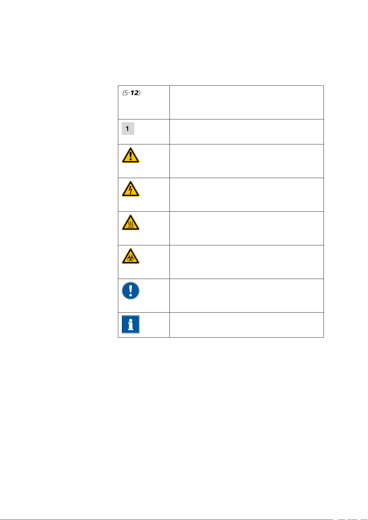
1.4 Symbols and conventions
The following symbols and styles are used in this documentation:
Cross-reference to figure legend
The first number refers to the figure number, the
second to the instrument part in the figure.
Instruction step
Carry out these steps in the sequence shown.
Warning
This symbol draws attention to a possible life hazard
or risk of injury.
Warning
This symbol draws attention to a possible hazard due
to electrical current.
1 Introduction
Warning
This symbol draws attention to a possible hazard due
to heat or hot instrument parts.
Warning
This symbol draws attention to a possible biological
hazard.
Caution
This symbol draws attention to a possible damage of
instruments or instrument parts.
Note
This symbol marks additional information and tips.
886 Professional Thermostat (2.886.0110) / 886 Professional Reactor (2.896.0210)
■■■■■■■■
3
Page 12
1.5 Safety instructions
1.5 Safety instructions
1.5.1 General notes on safety
Warning
This instrument may only be operated in accordance with the specifications in this documentation.
This instrument has left the factory in a flawless state in terms of technical
safety. To maintain this state and ensure non-hazardous operation of the
instrument, the following instructions must be observed carefully.
1.5.2 Electrical safety
The electrical safety when working with the instrument is ensured as part
of the international standard IEC 61010.
Warning
■■■■■■■■■■■■■■■■■■■■■■
Only personnel qualified by Metrohm are authorized to carry out service
work on electronic components.
Warning
Never open the housing of the instrument. The instrument could be
damaged by this. There is also a risk of serious injury if live components
are touched.
There are no parts inside the housing which can be serviced or replaced
by the user.
Mains voltage
Warning
An incorrect mains voltage can damage the instrument.
Only operate this instrument with a mains voltage specified for it (see
rear panel of the instrument).
■■■■■■■■
4
886 Professional Thermostat (2.886.0110) / 886 Professional Reactor (2.896.0210)
Page 13
■■■■■■■■■■■■■■■■■■■■■■
Protection against electrostatic charges
Warning
Electronic components are sensitive to electrostatic charges and can be
destroyed by discharges.
Always pull the mains cable out of the mains connection socket before
connecting or disconnecting electrical appliances on the rear panel of
the instrument.
1.5.3 Tubing and capillary connections
Caution
Leaks in tubing and capillary connections are a safety risk. Tighten all
connections well by hand. Avoid applying excessive force to tubing
connections. Damaged tubing ends lead to leakage. Appropriate tools
can be used to loosen connections.
1 Introduction
Check the connections regularly for leakage. If the instrument is used
mainly in unattended operation, then weekly inspections are mandatory.
1.5.4 Flammable solvents and chemicals
Warning
All relevant safety measures are to be observed when working with
flammable solvents and chemicals.
■ Set up the instrument in a well-ventilated location (e.g. laboratory
flue).
■ Keep all sources of flame far from the workplace.
■ Clean up spilled fluids and solids immediately.
■ Follow the safety instructions of the chemical manufacturer.
1.5.5 Recycling and disposal
This product is covered by European Directive 2002/96/EC, WEEE – Waste
from Electrical and Electronic Equipment.
The correct disposal of your old equipment will help to prevent negative
effects on the environment and public health.
886 Professional Thermostat (2.886.0110) / 886 Professional Reactor (2.896.0210)
■■■■■■■■
5
Page 14

1.5 Safety instructions
■■■■■■■■■■■■■■■■■■■■■■
More details about the disposal of your old equipment can be obtained
from your local authorities, from waste disposal companies or from your
local dealer.
■■■■■■■■
6
886 Professional Thermostat (2.886.0110) / 886 Professional Reactor (2.896.0210)
Page 15
■■■■■■■■■■■■■■■■■■■■■■
1 2
3
2
1
2 Overview of the instrument
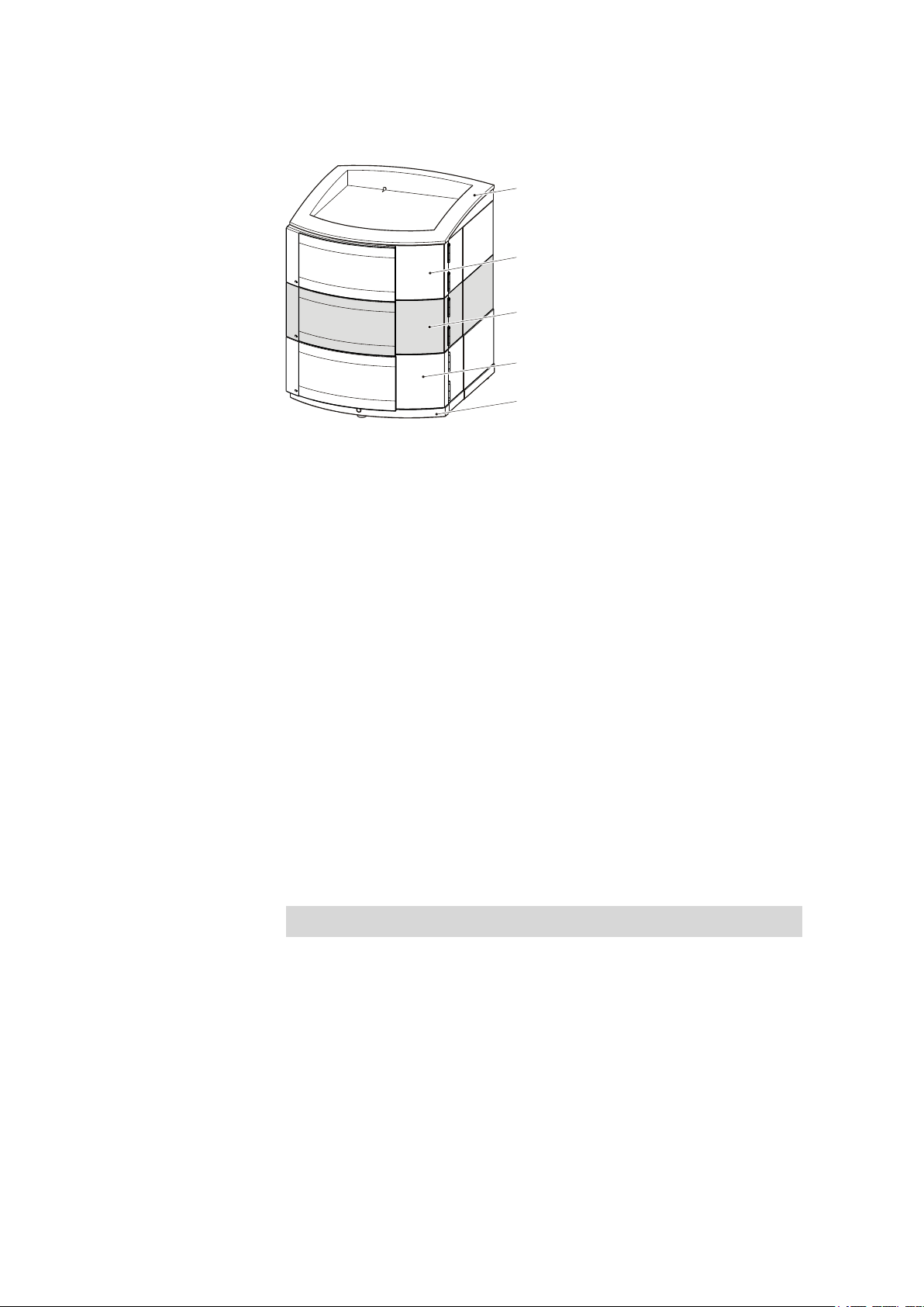
2.1 Front
2 Overview of the instrument
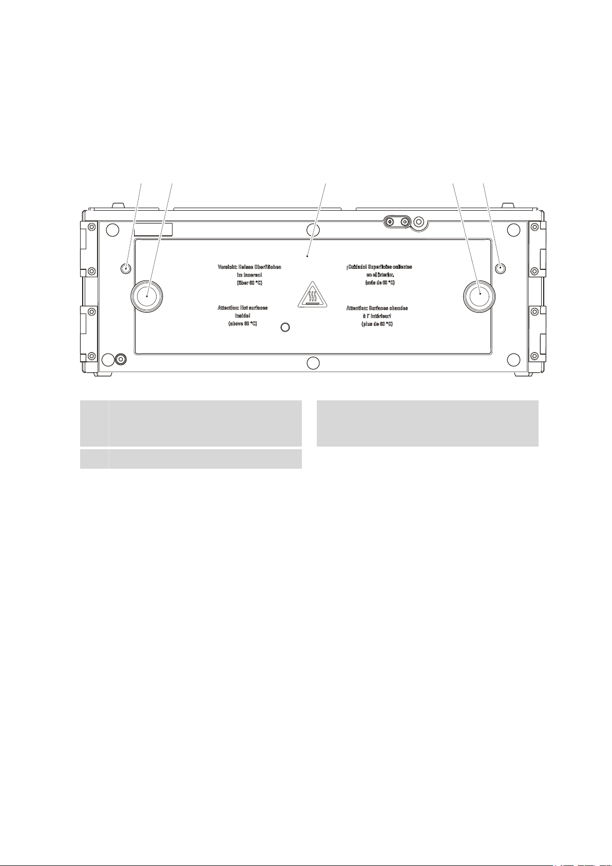
Figure 1 Front
1
3
Capillary feed-throughs
For feeding through the capillaries into the
oven.
Oven door
Knurled screws
2
For opening and closing the oven door.
886 Professional Thermostat (2.886.0110) / 886 Professional Reactor (2.896.0210)
■■■■■■■■
7
Page 16
2.2 Rear
1
2
3
4
5
6
7
8
2.2 Rear
■■■■■■■■■■■■■■■■■■■■■■
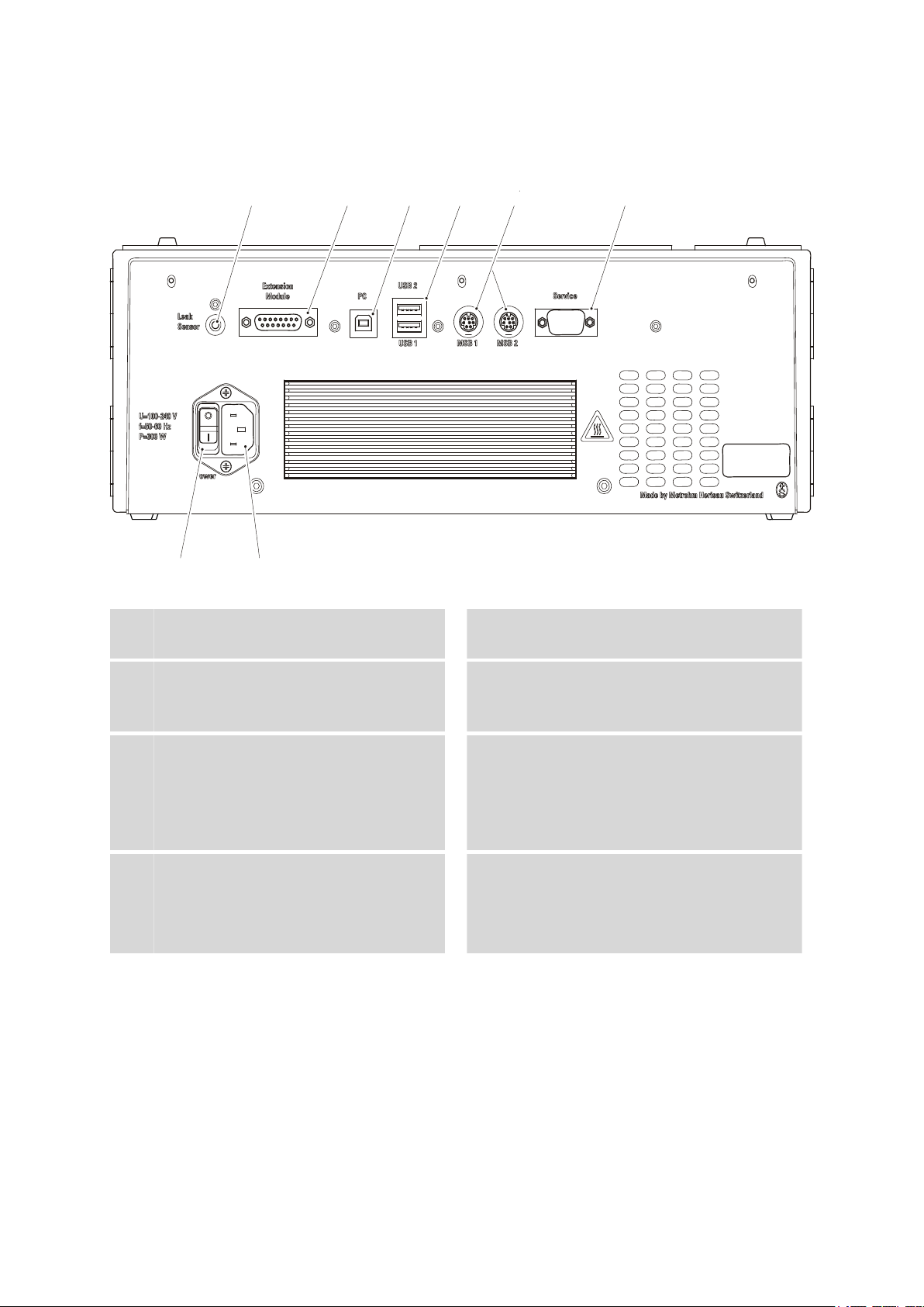
Figure 2 Rear
Leak sensor connection socket
1
For connecting the leak sensor.
PC connection socket
3
For connecting the instrument to the computer with the USB cable 6.2151.020.
MSB connection sockets
5
2 MSB connection sockets (labeled with
MSB 1 and MSB 2) for connecting MSB devices.
MSB = Metrohm Serial Bus
Mains switch
7
For switching the instrument on and off.
I = On
O = Off
Extension Module connection socket
2
To connect an extension module.
USB connection sockets
4
2 USB connection sockets (labeled with USB
1 and USB 2).
Service connection socket
6
Connector for service.
Mains connection socket
8
For plugging in the mains cable.
■■■■■■■■
8
886 Professional Thermostat (2.886.0110) / 886 Professional Reactor (2.896.0210)
Page 17
■■■■■■■■■■■■■■■■■■■■■■
4
3
1
2
1
2
3
4
6
6
5
7
2 Overview of the instrument
2.3 Accessories for 2.886.0110 Professional Reactor
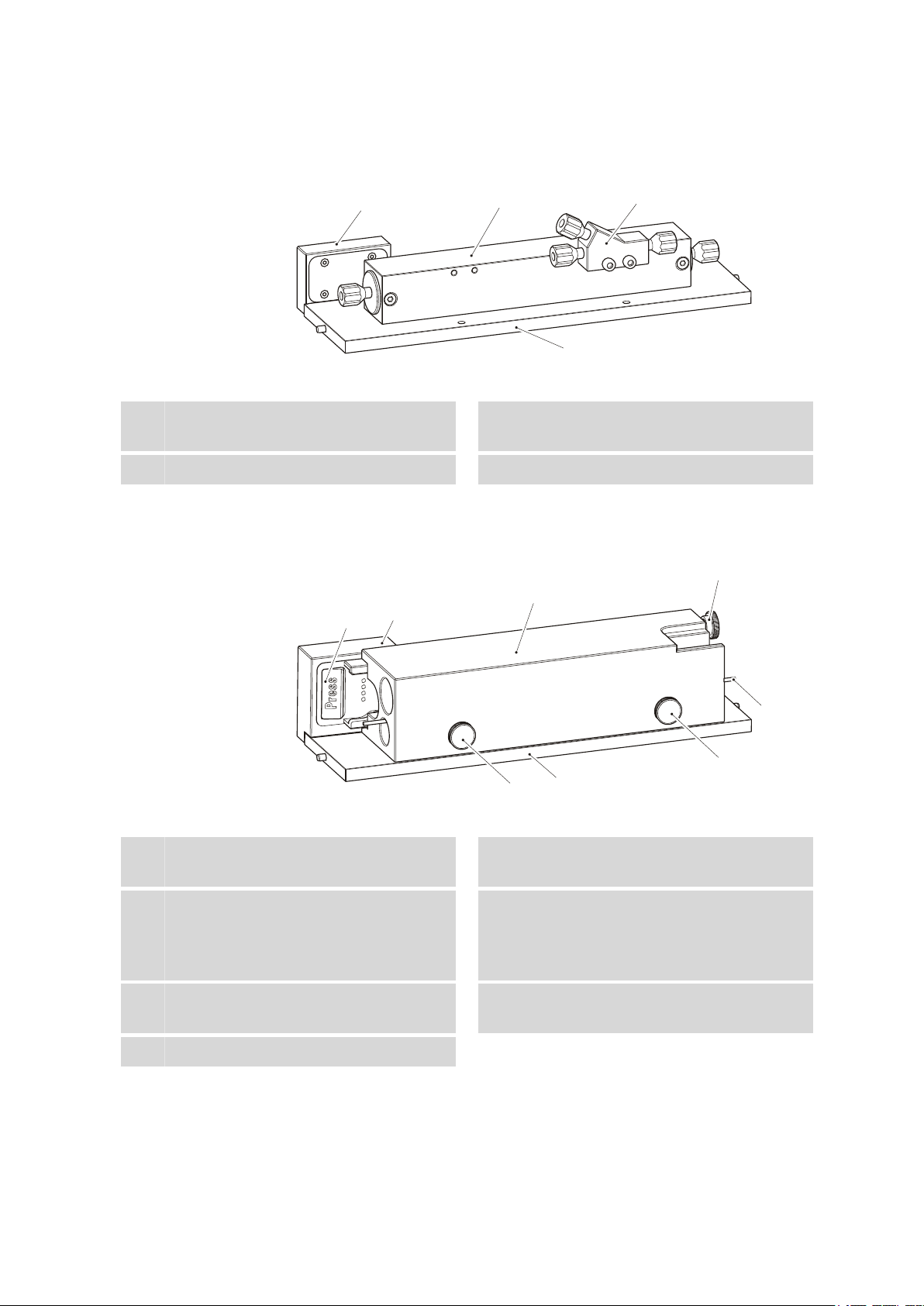
Figure 3 6.2845.100 Reactor plate
Heating plate
1
Reactor (6.2845.200)
3
Contact block
2
Connection between reactor plate and 886.
Y connector (6.2744.330)
4
2.4 Accessories for 2.886.0210 Professional Thermostat
Figure 4 6.2845.600 Column plate
Heating plate
1
Column holder
2
With column recognition chip.
Contact block
3
Connection between column plate and 886.
Knurled screw
5
For fixing the column.
Preheating capillary
7
Column block
4
With bore holes for maximum two columns
of 150 mm length and a preheating capillary.
Knurled screw
6
For fixing the preheating capillary.
886 Professional Thermostat (2.886.0110) / 886 Professional Reactor (2.896.0210)
■■■■■■■■
9
Page 18

3.1 Setting up the instrument
3 Installation
3.1 Setting up the instrument
3.1.1 Packaging
The instrument is supplied in highly protective special packaging together
with the separately packed accessories. Keep this packaging, as only this
ensures safe transportation of the instrument.
3.1.2 Checks
Immediately after receipt, check whether the shipment has arrived complete and without damage by comparing it with the delivery note.
3.1.3 Location
The instrument has been developed for operation indoors and may not be
used in explosive environments.
■■■■■■■■■■■■■■■■■■■■■■
Place the instrument in a location of the laboratory which is suitable for
operation, free of vibrations, protected from corrosive atmosphere, and
contamination by chemicals.
The instrument should be protected against excessive temperature fluctuations and direct sunlight.
3.2 Proposed setup
3.2.1 2.886.0110 Professional Reactor
An IC system with photometric detection and pre-column or post-column
derivatization consists of the 886 Professional Thermostat / Reactor and:
■ any 850 Professional IC instrument, or
any 881 Compact IC pro instrument, or
any 882 Compact IC plus instrument
■ the 887 Professional UV/VIS Detector
■ optionally: an 872 Extension Module for transporting the reagent solu-
tion
■ optionally, if the reagent is pumped with a high pressure pump: a Met-
rosep BP 1 Guard/2.0 backpressure column (6.1015.100)
■■■■■■■■
10
An IC system with photometric detection and pre-column or post-column
derivatization can be set up in in various combinations.
886 Professional Thermostat (2.886.0110) / 886 Professional Reactor (2.896.0210)
Page 19
■■■■■■■■■■■■■■■■■■■■■■
2.887.0010
2.886.0110
2.850.xxxx
2.872.xxxx
2.850.xxxx
2.872.xxxx
2.887.0010
2.886.0110
6.2061.100
6.2061.110
2.850.xxxx
2.881.xxxx
2.882.xxxx
2.887.0010
2.886.0110
2.872.xxxx
6.2061.110
6.2061.100
2.881.xxx
2.882.xxx
6.2061.120
2.872.xxxx
6.2061.100
2.887.0010
2.886.0110
6.2061.110
3 Installation
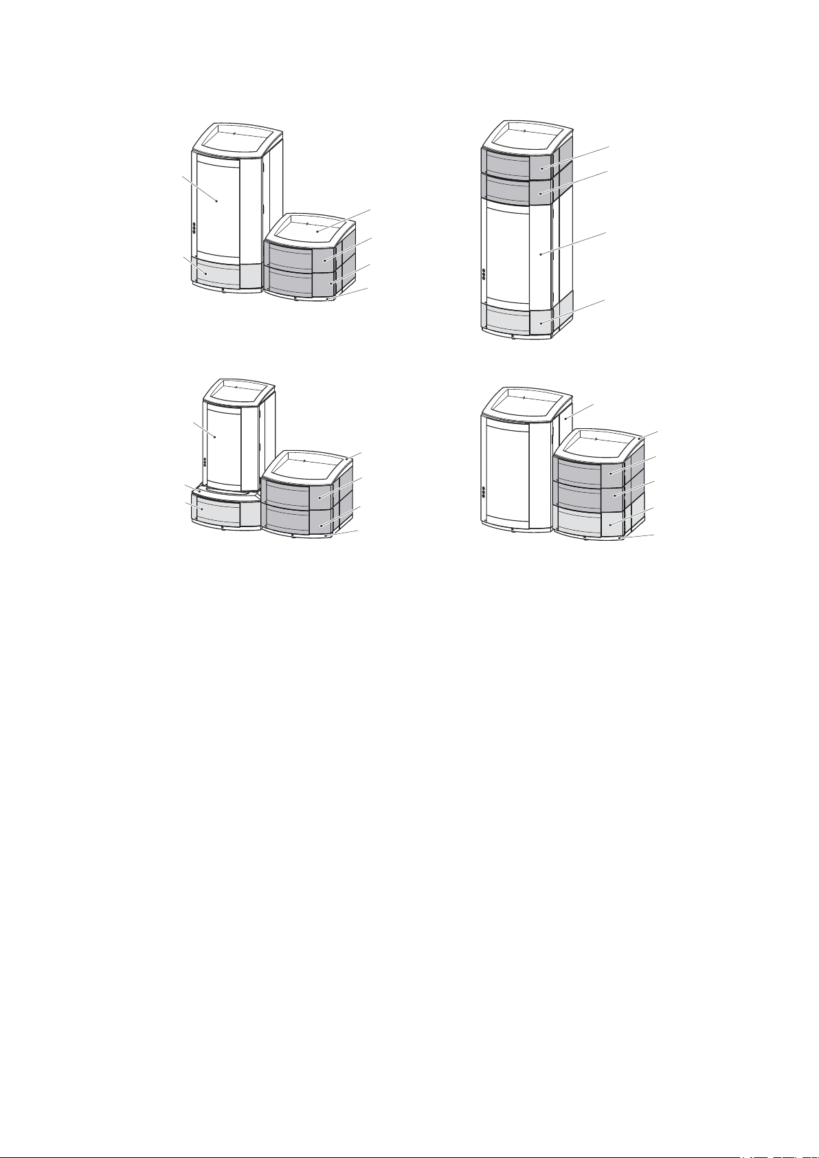
Figure 5 Proposed Setup – Professional Reactor
Note for proposed setup
If you want to set up the instruments in two stacks, we recommend you
protect the instruments of the second stack and also order the following
accessories:
■ 6.2061.100 Bottle holder (ProfIC)
■ 6.2061.110 Base tray with sensor for Professional IC systems
If you want to stack a 881 Compact IC pro or an 882 Compact IC plus
instrument with a 886 Professional Thermostat / Reactor, the 887 Professional UV/VIS Detector and/or a 872 Extension Module, you will require
the 6.2061.120 System Connector to adapt the different support surfaces.
3.2.2 2.886.0210 Professional Thermostat
In order to build an isocratic IC analysis system without a dedicated IC
instrument (850, 881, 882), you will require the 886 Professional Thermostat / Reactor and the following instruments:
■ a 2.872.0030 Extension Module – IC Module
■ any detector (e.g. the 2.887.0010 Professional UV/VIS Detector)
■ optionally an additional 872 Extension Module for sample preparation
886 Professional Thermostat (2.886.0110) / 886 Professional Reactor (2.896.0210)
■■■■■■■■
11
Page 20
3.3 Mounting base tray and bottle holder (optional)
6.2061.110
2.872.0030
2.886.0210
2.887.0010
6.2061.100
■■■■■■■■■■■■■■■■■■■■■■
For an isocratic IC analysis system with photometric detection (without
dedicated IC instrument) we recommend the following set up:
Figure 6 Proposed setup – Professional Thermostat
3.3 Mounting base tray and bottle holder (optional)
The 6.2061.110 base tray and 6.2061.100 bottle holder protect IC instruments from dust, dirt and leaking fluids. If more than one instrument of
the Professional IC family is used, these can be set up in one or more
stacks. We recommend that a bottle holder and a base tray be mounted
on/below each stack of instruments.
Bottle holder and base tray must be removed or mounted every time one
of the following instruments is mounted on or under an 850 Professional
IC instrument:
■ One or more 872 Extension Module.
■ An 886 Professional Thermostat / Reactor.
■ An 887 Professional UV/VIS Detector.
■ or another instrument of the same support surface.
3.3.1 Removing / mounting the base tray
The base tray must be removed, in case you want to place another instrument under the IC instrument. Proceed as follows:
Removing the base tray
Before you can remove the base tray, the following preconditions must be
met:
■■■■■■■■
12
■ The instrument is switched off.
■ The bottle holder is cleared.
■ All connections at the rear of the instrument are disconnected.
■ There are no loose parts in the instrument.
886 Professional Thermostat (2.886.0110) / 886 Professional Reactor (2.896.0210)
Page 21

■■■■■■■■■■■■■■■■■■■■■■
1
2
3
3 Installation
To remove the base tray, you need the 6.2621.100 hexagon key 3 mm.
Tilt the instrument sideways and lay it down flat.
1
Loosen the cylinder screws with the 3 mm hexagon key and remove
2
them and their washers.
Remove base tray.
3
The base tray must always be mounted under the lowermost instrument
of the stack. Proceed as follows:
Mounting the base tray
Before you can mount the base tray, the following preconditions must be
met:
■ The instrument is switched off.
■ The bottle holder is cleared.
■ All connections at the rear of the instrument are disconnected.
■ There are no loose parts in the instrument.
■ The instrument is lying on it side, and the bottom surface is visible.
To mount the base tray, you need the 3 mm hexagon key (6.2621.100).
886 Professional Thermostat (2.886.0110) / 886 Professional Reactor (2.896.0210)
■■■■■■■■
13
Page 22

3.3 Mounting base tray and bottle holder (optional)
1
3
2
Attach the base tray so that the openings in the base tray match
1
exactly the screw threads in the bottom of the instrument.
Slide the four washers onto the four cylinder screws, insert the
2
screws and tighten them with the 3 mm hexagon key.
Set the instrument up on the base tray.
3
■■■■■■■■■■■■■■■■■■■■■■
Stack other instruments in the required order. Mount the 6.2061.100 bottle holder onto the topmost instrument (see "Mounting the bottle
holder", page 15).
3.3.2 Removing / mounting the bottle holder
The bottle holder must be removed in case you want to mount another
instrument on top of the IC instrument. Proceed as follows:
Removing the bottle holder
Before you can remove the bottle holder, the following preconditions
must be met:
■ The instrument is switched off.
■ The bottle holder is cleared.
■ Drainage tubing is disconnected from the drainage tubing connection
of the bottle holder.
To remove the bottle holder, you need a 3 mm hexagon key
(6.2621.100).
■■■■■■■■
14
886 Professional Thermostat (2.886.0110) / 886 Professional Reactor (2.896.0210)
Page 23

■■■■■■■■■■■■■■■■■■■■■■
1
2 3
Remove the two covering stoppers.
1
Loosen the two cylinder screws with the 3 mm hexagon key and
2
remove them.
Remove the bottle holder.
3
3 Installation
Stack other instruments in the required order. Mount the 6.2061.100 bottle holder onto the topmost instrument (see "Mounting the bottle
holder", page 15).
Proceed as follows:
Mounting the bottle holder
Before you can mount the bottle holder, the following preconditions must
be met:
■ The instrument is switched off.
To mount the bottle holder, you need a 6.2621.100 hexagon key 3 mm.
886 Professional Thermostat (2.886.0110) / 886 Professional Reactor (2.896.0210)
■■■■■■■■
15
Page 24

3.3 Mounting base tray and bottle holder (optional)
1
2 3
Attach the bottle holder onto the topmost instrument so that the
1
openings in the bottle holder exactly match the screw threads on the
top surface of the instrument.
Insert the two cylinder screws and tighten them with the 3 mm hexa-
2
gon key.
Insert covering stoppers .
3
■■■■■■■■■■■■■■■■■■■■■■
After having attached the bottle holder, all connections which were
undone at the beginning of the process, must be reconnected. Proceed as
follows:
Restoring the loosened connections
Connect the USB cable.
1
Connect the MSB cable.
2
Plug in the mains cable.
3
Reconnect drainage tubings (see manual of the IC instrument).
4
Possibly, a longer section of silicone tubing 6.186.020 must be cut to
fit and mounted (see also the manual for the IC instrument).
If one of the instruments in the stack is equipped with a leak sensor
5
connection socket, connect the leak sensor (see manual of the IC
instrument).
■■■■■■■■
16
886 Professional Thermostat (2.886.0110) / 886 Professional Reactor (2.896.0210)
Page 25

■■■■■■■■■■■■■■■■■■■■■■
4
1
2 3
3.4 Capillary connections in the IC system
This chapter contains general information concerning the capillary connections in the IC instruments and systems.
Generally speaking, capillary connections between two components of an
IC system are made up of one connection capillary and two pressure
screws with which the capillary is connected to the respective components.
Pressure screws
3 Installation
Figure 7 Connection of capillaries with pressure screws
PEEK pressure screw (6.2744.014)
1
Use on the injection valve.
PEEK pressure screw, short
3
(6.2744.070)
For use on the high pressure pump, the
purge valve, the inline filter, the pulsation
absorber, the guard column and the separation column.
In order to keep the dead volume as low as possible, capillary connections should generally be as short as possible.
For an improved overview, capillary and tubing connections can be
bundled with the 6.1815.010 spiral band.
Note
Note
Connection capillary
2
PEEK pressure screw, long
4
(6.2744.090)
Use on special components. Is not used on
all instruments.
886 Professional Thermostat (2.886.0110) / 886 Professional Reactor (2.896.0210)
■■■■■■■■
17
Page 26

3.4 Capillary connections in the IC system
Connection capillaries
PEEK capillaries and PTFE capillaries are used in the IC system.
■■■■■■■■■■■■■■■■■■■■■■
PEEK capillaries (polyetheretherketone)
PTFE capillaries (polytetrafluoroethylene)
PEEK capillaries are temperature-resistant up to 100°C, stable under pressure up to 400 bar, flexible, chemically inert and exhibit an extremely
smooth surface. They can be readily cut down to the desired length with
the 6.2621.080 capillary cutter.
Usage:
■ PEEK capillaries (6.1831.010) with an internal diameter of 0.25 mm for
the entire high pressure range.
■ PEEK capillaries (6.1831.030) with an internal diameter of 0.75 mm for
sample handling in the ultra trace range.
PTFE capillaries are transparent and enable visual tracing of the liquids to
be pumped. They are chemically inert, flexible and temperature-resistant
up to 80°C.
Usage:
PTFE capillaries (6.1803.0x0) are used for the low pressure range.
■ PTFE capillaries with internal diameter of 0.5 mm for sample handling.
■ PTFE capillaries with internal diameter of 0.97 mm for sample handling
as well as for rinsing solutions (they do not have to be in the scope of
delivery of the instrument).
Capillary connections
In order to achieve optimum analysis results, capillary connections in an IC
system must be absolutely tight and free of dead volume. Dead volume
occurs if two capillary ends connected to each other do not fit exactly,
thus allowing liquid to escape. There are two possible reasons for this:
■ The capillaries do not have exactly cut edges.
■ The two capillary ends do not completely meet.
One prerequisite for dead volume free capillary connection is, that both
capillary ends are cut exactly plane. Therefore we recommend only to cut
PEEK capillaries with the capillary cutter (6.2621.080).
Creating dead volume free capillary connections
To create dead volume free capillary connections, proceed as follows:
Slide the pressure screw over the capillary. Ensure that the capillary
1
protrudes 1–2 mm from the tip of the pressure screw.
■■■■■■■■
18
886 Professional Thermostat (2.886.0110) / 886 Professional Reactor (2.896.0210)
Page 27

■■■■■■■■■■■■■■■■■■■■■■
3 Installation
Plug the capillary all the way into the connection or coupling until
2
the stop.
Only then start turning the pressure screw, while keeping the capil-
3
lary pressed in space.
Colored sleeves for PEEK capillaries
The enclosed set of varicolored sleeves for PEEK capillaries (6.2251.000)
serves to easily differentiate the various flows of liquid in the system
through color coding. Each capillary leading a given liquid (e. g. eluent)
can be highlighted with sleeves of the same color.
To highlight a capillary, proceed as follows:
Slide a sleeve of a selected color over a capillary an move it to an
1
easily visible position.
If the capillary heats up, the sleeve shrinks and adapts to the form of
the capillary.
3.5 Installations on the rear of the instrument
3.5.1 Connecting the leak sensor
The leak sensor detects escaping liquid which collects in the base tray of
the instrument.
To activate the leak sensor, the leak sensor connector plug (8-2) must be
connected, the instrument switched on and the leak sensor switched to
active in the software.
Connecting the leak sensor
■ Pull the cable of the leak sensor (8-3) out of the rear of the base
1
tray.
■ Plug the leak sensor connector plug (8-2) into the leak sensor
connection socket (8-1) on the rear of the instrument.
886 Professional Thermostat (2.886.0110) / 886 Professional Reactor (2.896.0210)
■■■■■■■■
19
Page 28

3.6 Capillary and cable feed-throughs
1
2
3
Figure 8 Connecting the leak sensor
■■■■■■■■■■■■■■■■■■■■■■
Leak sensor connection socket
1
Is labeled with "Leak Sensor".
Leak sensor connection cable
3
Is firmly mounted on the rear of the instrument.
Leak sensor connector plug
2
3.6 Capillary and cable feed-throughs
Several openings have been integrated for feeding through capillaries and
cables. To feed through capillaries into the oven, two openings are provided, one each left and right of the oven door. Up to five capillaries can be
fed into the oven through each of the two capillary feed-throughs.
■■■■■■■■
20
Figure 9 Capillary feed-throughs – oven
To guide capillaries to or away from the instrument or to guide them
between two instruments, use the capillary feed-throughs on top or at the
886 Professional Thermostat (2.886.0110) / 886 Professional Reactor (2.896.0210)
Page 29

■■■■■■■■■■■■■■■■■■■■■■
3 Installation
bottom of the instrument. These are designed to guide capillaries
between two instruments or between instrument an base plate or instrument an bottle holder.
Figure 10 Capillary feed-throughs – instrument
3.7 Opening / closing oven door
The heatable interior of the 886 Professional Thermostat / Reactor is
closed with a well isolating oven door. In order to insert the required
accessories into the oven, the oven door must be opened. Proceed as follows:
Opening the oven door
Warning
Surfaces inside of the oven and the oven door can be hotter than 60
°C.
Risk of burns!
Let the oven cool down after use and open oven door carefully. Place
oven door on a fire resistant surface.
Loosen the knurled screws on both sides of the oven door, and care-
1
fully remove oven door.
Place oven door on a fire resistant surface.
2
886 Professional Thermostat (2.886.0110) / 886 Professional Reactor (2.896.0210)
■■■■■■■■
21
Page 30

3.8 Installing accessories
1
2
3
■■■■■■■■■■■■■■■■■■■■■■
Figure 11 Front – open
Oven door
1
Heating plate
3
2
Before the determination can be started, the oven door must be tightly
closed. Proceed as follows:
Closing oven door
Place oven door onto opening. Make sure that no capillaries are
1
pinched.
Tighten both knurled screws at the front of the oven by hand.
2
3.8 Installing accessories
3.8.1 2.886.0110 Professional Reactor
Equipped with the 6.2845.100 reactor plate, the 886 Professional Thermostat / Reactor provides the functionality of a pre- or post-column reactor.
Oven interior
■■■■■■■■
22
The easiest way to connect capillaries is outside the oven.
All capillaries must be fed into or out of the oven through the capillary
feed-throughs at the right and left side of the oven door (see Figure 9,
page 20).
If you have placed the 886 Professional Thermostat / Reactor under or
next to the IC instrument, proceed as follows:
1. Feeding capillaries into the oven
886 Professional Thermostat (2.886.0110) / 886 Professional Reactor (2.896.0210)
Page 31

■■■■■■■■■■■■■■■■■■■■■■
3 Installation
2. Connect capillaries to the reactor
3. Insert reactor plate
Start with "Feeding capillaries into the oven", page 24.
If you have placed the 886 Professional Thermostat / Reactor on top of
the IC instrument, proceed as follows:
1. Connect capillaries to the reactor
2. Insert reactor plate
3. Guide capillaries out of the oven
Start with "Connect the capillaries", page 24
To deliver the reagent, you need either an additional high pressure pump
or an additional peristaltic pump. If you deliver the reagent with a high
pressure pump, you must install the 6.1015.100 Metrosep BP 1 Guard/2.0
backpressure column between the reactor and the pulsation absorber.
Note
In order to keep the dead volume as low as possible, make sure that
capillary connections are as short as possible.
Always shorten capillaries with the 6.2621.080 capillary cutter to obtain
flawless level cut capillary ends.
886 Professional Thermostat (2.886.0110) / 886 Professional Reactor (2.896.0210)
■■■■■■■■
23
Page 32

3.8 Installing accessories
1
2
3
1
5
2
3
4
■■■■■■■■■■■■■■■■■■■■■■
Feeding capillaries into the oven
Figure 12 Feeding capillaries into the oven – reactor
Reactor inlet capillary
1
Reactor outlet capillary
3
Reagent inlet capillary
2
1
Feed capillaries into the oven
■ Guide the reactor inlet capillary, the reagent inlet capillary (section
of 6.1831.100), and the reactor outlet capillary through the two
capillary feed-throughs on the right and left side of the oven door
(see Figure 9, page 20) into the oven.
Connect the capillaries
Figure 13 Reactor plate – capillaries connected
Reactor inlet capillary
1
■■■■■■■■
24
886 Professional Thermostat (2.886.0110) / 886 Professional Reactor (2.896.0210)
Connection capillary
2
Section of PEEK capillary (6.1831.100).
Page 33

■■■■■■■■■■■■■■■■■■■■■■
3 Installation
Reactor outlet capillary
3
Section of PEEK capillary (6.1831.100) or the
PTFE capillary (6.1803.150)
Backpressure column
5
*
Metrosep BP 1 Guard/2.0 (6.1015.100)
*
In bromate determination with the tri-iodide method, the tri-iodide is
partially absorbed by the PEEK capillary, which leads to peak widening and
a lower detection limit. Therefore, for this application, we recommend to
use the PTFE capillary (6.1803.150).
To connect the capillaries, you need the following accessories:
■ the long PEEK capillary (6.1831.100)
■ the capillary cutter (6.2621.080)
■ If the reagent is delivered via high pressure pump: the backpressure
column 6.1015.100 Metrosep BP 1 Guard/2.0
1
Connect the reactor inlet capillary
■ Attach the column outlet capillary (13-1) to one of the two Y con-
■ Connect the Y connector output and reactor input with a short
2
Connect the reagent inlet capillary
■ For reagent delivery, attach a section of the 6.1831.100 PEEK
■ Attach the backpressure column (13-5) at he other end.
■ Attach another section of the 6.1831.100 PEEK capillary to the
3
Connect the reactor outlet capillary
Reagent inlet capillary
4
Section of PEEK capillary (6.1831.100)
nector inlets.
section of the 6.1831.100 PEEK capillary (13-2).
capillary to the second Y connector inlet.
other end of the backpressure column (13-4).
■ Attach a section of the 6.1831.100 PEEK capillary (13-3) at the
reactor output.
Inserting the reactor plate (6.2845.100)
To insert the reactor plate, you need the 6.2621.140 hexagon key 2.5
mm.
886 Professional Thermostat (2.886.0110) / 886 Professional Reactor (2.896.0210)
■■■■■■■■
25
Page 34

3.8 Installing accessories
1 2
3
4
■■■■■■■■■■■■■■■■■■■■■■
1
Lowering the latches
Loosen the outer screws of both latches with the 6.2621.140 2.5
mm hexagon key turning them counterclockwise.
The latches open and unblock the insertion rails of the heating plate.
2
Insert reactor plate
■ Insert the reactor plate into the oven by fitting the two bolts at
the sides of the reaction plate into the insertion rails of the heating plate.
■ Slide the reactor plate into the oven as far as it will go. Take care
not to jam or pinch the capillaries.
3
Lift the latches
Tighten the outer screws of both latches with the 6.2621.140 hexagon key 2.5 mm turning them clockwise.
The latches lift and fix the column holder on the heating plate.
4
Connect the capillaries to the system
In case the free capillary ends are not yet guided through the capillary feed-throughs, guide them out of the oven.
■ Connect the loose end of the reactor inlet capillary (13-1) with
the outlet of the separation column.
■■■■■■■■
26
886 Professional Thermostat (2.886.0110) / 886 Professional Reactor (2.896.0210)
Page 35

■■■■■■■■■■■■■■■■■■■■■■
3 Installation
■ Connect the loose end of the reactor outlet capillary (13-3) with
the detector inlet.
■ Connect the loose end of the reagent inlet capillary (13-4) with
either
– an unused high pressure pump (recommended), and make
sure that the 6.1015.100 Metrosep BP 1 Guard/2.0 backpressure column is installed between the reactor and the
pulsation absorber,
or
– an unused peristaltic pump.
The reaction capillary inside the reactor is 2 m long and has a volume of
393 µL. This is sufficient for most applications. Should an application
require a longer reaction time, or if the 886 Professional Thermostat /
Reactor is used in a two channel IC system, the reactor plate can be
equipped wit additional reactors (6.2845.200). A maximum of four reactors can be mounted on the reactor plate.
To mount additional reactors, proceed as follows:
886 Professional Thermostat (2.886.0110) / 886 Professional Reactor (2.896.0210)
■■■■■■■■
27
Page 36

3.8 Installing accessories
1
6.2845.200
6.2845.200
2
6.2845.200
6.2845.200
6.2845.200
6.2845.200
3
6.2845.200
6.2845.200
6.2845.200
6.2845.200
4
6.2845.200
6.2845.200
6.2845.200
6.2845.200
■■■■■■■■■■■■■■■■■■■■■■
Optional: attaching additional reactors
To attach additional reactors, you need the following accessories:
■ 6.2845.200 Reactor complete
■ 6.2621.140 hexagon key 2.5 mm
1
Attach two reactors
The originally mounted reactor is attached to the reactor plate with
four screws turned in from the bottom of the plate.
■ Remove the four screws using the 2.5 mm hexagon key.
■ Reattach the reactor at the far end of the reactor plate.
■ Attach a second reactor from the 6.2845.200 accessory set at the
front end of the reactor plate using the the included screws and
the 2.5 mm hexagon key.
2
Attach additional reactors
■ Place two additional reactors on top of the other two.
3
Fasten the reactors
■ Fasten each reactor on both sides to the reactor below using the
included clips.
■■■■■■■■
28
886 Professional Thermostat (2.886.0110) / 886 Professional Reactor (2.896.0210)
Page 37

■■■■■■■■■■■■■■■■■■■■■■
4
Mount the Y connector
6.2744.330 Y connectors are used to add the reagent. These are
supplied with each 6.2845.200 reactor. You can attach several Y
connectors to the reactor block.
■ Attach the Y connectors to the reactors using the included
screws.
3.8.2 2.886.0210 Professional Thermostat
Equipped with the 6.2845.600 column holder, the 886 Professional Thermostat / Reactor provides the functionality of a column thermostat.
The easiest way to connect capillaries is outside the oven.
All capillaries must be fed into or out of the oven through the capillary
feed-throughs at the right and left side of the oven door.
If you have placed the 886 Professional Thermostat / Reactor under or
next to the IC instrument, proceed as follows:
3 Installation
1. Feeding capillaries into the oven
2. Connect the capillaries with the columns
3. Insert column holder
Start with "Feeding capillaries into the oven", page 24.
If you have placed the 886 Professional Thermostat / Reactor on top of
the IC instrument, proceed as follows:
1. Connect the capillaries with the columns
2. Insert column plate
3. Guide capillaries out of the oven
Start with "Connect the capillaries", page .24
Note
In order to keep the dead volume as low as possible, make sure that
capillary connections are as short as possible.
Always shorten capillaries with the 6.2621.080 capillary cutter to obtain
flawless level cut capillary ends.
886 Professional Thermostat (2.886.0110) / 886 Professional Reactor (2.896.0210)
■■■■■■■■
29
Page 38

3.8 Installing accessories
1
2
■■■■■■■■■■■■■■■■■■■■■■
Feeding capillaries into the oven
Figure 14 Feeding capillaries into the oven – thermostat
Column inlet capillary
1
Column outlet capillary
2
1
Feed capillaries into the oven
■ Guide the column inlet capillary and the column outlet capillary
through the two capillary feed-throughs at the left and right side
of the oven door.
The column holder can hold two columns with a maximum length of 150
mm. If one of the columns is an iColumn, the system ensures that the
oven is not heated up higher than the standard operating temperature of
the column. You can also use columns without chip, in this case you have
to set the maximum oven temperature manually.
The second bore hole of the column block can also hold additional columns and/or guard columns with a total length of 150 mm. For applications requiring a 250 mm column, you can combine a 150 mm iColumn
with a second 100 mm column and an on column guard column. The following figure illustrates how the preheating capillary and the columns are
connected.
■■■■■■■■
30
886 Professional Thermostat (2.886.0110) / 886 Professional Reactor (2.896.0210)
Page 39

■■■■■■■■■■■■■■■■■■■■■■
1
2
3
4
5
3 Installation
Figure 15 Connecting the columns
Main column
1
iColumn clicked into the column holder.
Maximum length: 150 mm.
Preheating capillary
3
Part of accessories set 6.2845.600.
Capillary
5
Connection between main column and
detector.
Connecting and inserting columns
To install the columns, you need:
■ main column: an intelligent separation column (iColumn) of maximum
150 mm length (e.g. Metrosep A Supp 15 -150/4.0)
■ auxiliary column: a guard column compatible with the main column
(e.g. Metrosep A Supp 15 S-Guard/4.0) or
a second column compatible with the main column (e.g. Metrosep A
Supp 15 - 100/4.0) with an on column guard column (Metrosep A
Supp 15 Guard/4.0)
■ sections of the included capillary 6.1831.100
■ the capillary cutter (6.2621.080)
Auxiliary column
2
Either a second column (of 100 mm length)
with on column guard system or guard column only.
Capillary
4
Connection between main column and auxiliary column.
886 Professional Thermostat (2.886.0110) / 886 Professional Reactor (2.896.0210)
■■■■■■■■
31
Page 40

3.8 Installing accessories
1
2
3
4
5 6
■■■■■■■■■■■■■■■■■■■■■■
1
Insert main column
■ Slide the main column into the rear bore hole of the column
block.
■ Click the head of the column into the column holder at the con-
tact block.
2
Connect auxiliary column
■ Connect the input of the main column with the output of the
guard column. Use the connection capillary included with the
guard column.
■■■■■■■■
32
886 Professional Thermostat (2.886.0110) / 886 Professional Reactor (2.896.0210)
Page 41

■■■■■■■■■■■■■■■■■■■■■■
3 Installation
■ If you want to use a second column with on column guard col-
umn, use a section of the 6.1831.100 capillary to connect the
two columns.
3
Insert additional column
■ Slide the auxiliary column into the upper bore hole of the column
block.
4
Connect preheating capillary
The preheating capillary (15-3) is inserted in the lower bore hole of
the column block and secured from sliding out with two knurled
screws situated at the front of the column block.
■ Before connecting the preheating capillary, loosen these knurled
screws and pull the preheating capillary out of the bore hole.
■ Connect the preheating capillary and the input of the auxiliary col-
umn.
5
Insert preheating capillary
■ Slide the preheating capillary back into its bore hole.
■ Secure it from sliding out by fastening the two knurled screws.
6
Connect column outlet capillary
■ Attach a section of the 6.1831.100 capillary (15-5) to the outlet
of the column.
Inserting the column plate
To insert the column plate, you need the 6.2621.140 hexagon key 2.5
mm.
886 Professional Thermostat (2.886.0110) / 886 Professional Reactor (2.896.0210)
■■■■■■■■
33
Page 42

3.8 Installing accessories
1
2
3
4
■■■■■■■■■■■■■■■■■■■■■■
1
Lower the latches
Loosen the outer screws of both latches with the 6.2621.140 hexagon key 2.5 mm turning them counterclockwise.
The latches open and unlock the insertion rails of the heating plate.
2
Insert the column plate
■ Insert the column plate into the oven by fitting the two bolts at
the sides of the column plate into the insertion rails of the heating
plate.
■ Slide the column plate into the oven as far as it will go. Take care
not to jam or pinch the capillaries.
3
Lift the latches
Tighten the outer screws of both latches with the 6.2621.140 hexagon key 2.5 mm turning them clockwise.
The latches lift and fix the column holder on the heating plate.
4
Connect the capillaries to the system
In case the free capillary ends are not yet guided through the capillary feed-throughs, guide them out of the oven.
■ Connect the free end of the preheating capillary with the injection
valve.
■■■■■■■■
34
886 Professional Thermostat (2.886.0110) / 886 Professional Reactor (2.896.0210)
Page 43

■■■■■■■■■■■■■■■■■■■■■■
■ Connect the free end of the column outlet capillary with the
detector.
3.9 Connecting the instrument
3.9.1 Connecting the instrument to the PC
Note
The instrument must be switched off when connecting the PC.
1
Connecting the USB cable
Connect the PC connection socket of the instrument to a USB connector of the computer via the 6.2151.020 USB cable.
3.9.2 Connecting the instrument to mains supply
3 Installation
Warning
The power supply unit must not get wet. Protect it against the direct
effect of liquids.
Mains cable
Which mains cable is supplied depends on the location:
■ 6.2122.020 with plug SEV 12 (Switzerland, …)
■ 6.2122.040 with plug CEE(7), VII (Germany, …)
■ 6.2122.070 with plug NEMA 5-15 (USA, …)
The mains cable is three-core and provided with a plug with grounding. If
another plug has to be mounted, the yellow/green conductor (IEC standard) must be connected to the protective ground (protection class I).
1
Connecting the mains cable
■ Plug the mains cable into the mains connection socket .
■ Connect the mains cable to the mains supply.
2
Switching the instrument on and off
Switch the instrument on and off with the mains switch .
886 Professional Thermostat (2.886.0110) / 886 Professional Reactor (2.896.0210)
■■■■■■■■
35
Page 44

4 Start-up
■■■■■■■■■■■■■■■■■■■■■■
The 886 Professional Thermostat / Reactor is set up together wit other
instruments, e.g. an 850 Professional IC and the 887 Professional UV/VIS
Detector.
Putting the 886 Professional Thermostat / Reactor into
operation
Start MagIC Net.
1
Connect the 886 Professional Thermostat / Reactor to PC and switch
2
on.
The 886 Professional Thermostat / Reactor is recognized automatically by MagIC Net.
■■■■■■■■
36
886 Professional Thermostat (2.886.0110) / 886 Professional Reactor (2.896.0210)
Page 45

■■■■■■■■■■■■■■■■■■■■■■
5 Operation
5 Operation
The instrument is operated via MagIC Net software only. Additional information on operating MagIC Net can be found in the document "Tutorial
for MagIC Net" or in the online help.
886 Professional Thermostat (2.886.0110) / 886 Professional Reactor (2.896.0210)
■■■■■■■■
37
Page 46

6.1 General notes
6 Handling and maintenance
6.1 General notes
6.1.1 Care
Warning
The instrument housing must not be opened by untrained personnel.
The instrument requires appropriate care. Excess contamination of the
instrument may result in functional disruptions and a reduction in the service life of the sturdy mechanics and electronics.
Caution
■■■■■■■■■■■■■■■■■■■■■■
Although this is prevented to a great extent by design measures, the
mains plug should be unplugged immediately if aggressive media has
penetrated the inside of the instrument, so as to avoid serious damage
to the instrument electronics. In such cases, the Metrohm Service must
be informed.
Spillages of chemicals and solvents should be cleaned up immediately. In
particular, the plug connections on the rear panel of the instrument (especially the mains plug) should be protected from contamination.
6.1.2 Maintenance by Metrohm Service
Maintenance of the instrument is best carried out as part of an annual
service, which is performed by specialist personnel from Metrohm. If
working frequently with caustic and corrosive chemicals, a shorter maintenance interval is recommended. The Metrohm service department offers
every form of technical advice for maintenance and service of all Metrohm
instruments.
6.1.3 Operation
Caution
■■■■■■■■
38
In order to avoid disturbing temperature influences, the entire system
including the eluent bottle must be protected against direct sunlight.
886 Professional Thermostat (2.886.0110) / 886 Professional Reactor (2.896.0210)
Page 47

■■■■■■■■■■■■■■■■■■■■■■
6.1.4 Shutting down
If the instrument is not used for a longer period, the whole IC system
(except the columns) must be rinsed salt free with methanol/ultrapure
water (1:4), in order to prevent eluent salts and reagents from forming
crystals which may cause subsequent damage.
Rinsing salt free the IC system
To rinse the system, proceed as follows:
Remove the separation column from the eluent path. Connect the
1
connection capillaries directly with each other using a coupling
(6.2744.040).
Rinse the IC system with methanol/ultrapure water (1:4) for 15
2
minutes.
Rinse with eluent for at least 15 minutes at starting up again and before
connecting the guard column and separation column.
6 Handling and maintenance
6.2 Door
Caution
The door is made of PMMA (polymethylmetacrylate). It must never be
cleaned with abrasive media or solvents.
Caution
Never hold the instrument at the door when lifting or moving.
886 Professional Thermostat (2.886.0110) / 886 Professional Reactor (2.896.0210)
■■■■■■■■
39
Page 48

■■■■■■■■■■■■■■■■■■■■■■
7 Quality Management and validation with
Metrohm
Quality Management
Metrohm offers you comprehensive support in implementing quality management measures for instruments and software. Further information on
this can be found in the brochure «Quality Management with
Metrohm» available from your local Metrohm agent.
Validation
Please contact your local Metrohm agent for support in validating instruments and software. Here you can also obtain validation documentation
to provide help for carrying out the Installation Qualification (IQ) and
the Operational Qualification (OQ). IQ and OQ are also offered as a
service by the Metrohm agents. In addition, various application bulletins
are also available on the subject, which also contain Standard Operat-
ing Procedures (SOP) for testing analytical measuring instruments for
reproducibility and correctness.
Maintenance
Electronic and mechanical functional groups in Metrohm instruments can
and should be checked as part of regular maintenance by specialist personnel from Metrohm. Please ask your local Metrohm agent regarding the
precise terms and conditions involved in concluding a corresponding
maintenance agreement.
Note
You can find information on the subjects of quality management, validation and maintenance as well as an overview of the documents currently available at www.metrohm.com/com/ under Support.
■■■■■■■■
40
886 Professional Thermostat (2.886.0110) / 886 Professional Reactor (2.896.0210)
Page 49

■■■■■■■■■■■■■■■■■■■■■■
8 Troubleshooting
8.1 Problems and their solutions
Problem Cause Remedy
8 Troubleshooting
Marked drop in
pressure
Drift of the baseline
Extreme spread of
the peaks in the
chromatogram.
Splitting (dual
peaks)
Leak in the system.
Thermal equilibrium not yet
attained.
Leak in the system.
Capillary connections –
dead volume in the system.
Check all capillary connections and seal leaks,
if necessary (see Chapter 3.4, page 17).
Condition instrument with the column heater
switched on.
Check all capillary connections and seal leaks,
if necessary (see Chapter 3.4, page 17).
Check connections (see Chapter 3.4, page 17)
(use PEEK capillaries with an internal diameter
of 0.25 mm between the injection valve and
detector).
886 Professional Thermostat (2.886.0110) / 886 Professional Reactor (2.896.0210)
■■■■■■■■
41
Page 50

9.1 Reference conditions
9 Technical specifications
9.1 Reference conditions
The technical specifications listed in this chapter refer to the following reference conditions:
■■■■■■■■■■■■■■■■■■■■■■
Ambient temperature
Instrument status
+25 °C (±3 °C)
> 40 min in operation
9.2 Instrument
IC system
Intelligent components
Connections for
external components
Metal free system for heating intelligent reactors and columns.
iColumns, iReactors, Dosinos
■ up to three extension modules for reagent delivery etc.
■ up to two Dosinos
■ Analog data output (optional)
9.3 Leak sensor
Type
Electronic, no calibration necessary
9.4 Ambient conditions
Operation
Storage
Transport
■■■■■■■■
42
Ambient temperature
Humidity
Ambient temperature
Ambient temperature
+5…+45 °C
20…80 % relative humidity
–20…+70 °C
–40…+70 °C
886 Professional Thermostat (2.886.0110) / 886 Professional Reactor (2.896.0210)
Page 51

■■■■■■■■■■■■■■■■■■■■■■
9.5 Housing
Dimensions
Width
Height
Depth
9 Technical specifications
365 mm
131 mm
380 mm
Material of base
tray, housing and
covering plate
Operating elements
Indicators
On/Off switch
Polyurethane hard foam (PUR) with flame retardation
LED for power display
On the rear of the instrument
9.6 Reactor / Column thermostat
Number of reactors
Number of columns
Adjustable temperature range
Stability
Reproducibility
up to 4
up to 2
0 °C…+150 °C, adjustable in steps of 0.1 °C
less than 0.05 °C deviation
better than ± 0.2 °C
Temperature
accuracy
Heating up time
Maximum pressure
Reactor
Heating type
safety shutdown
Function
Maximum temperature
886 Professional Thermostat (2.886.0110) / 886 Professional Reactor (2.896.0210)
< 1 °C (typical)
< 10 Min. from 20 °C to 40 °C
2 MPa
Resistor type thermostat for intelligent reactors and intelligent separation columns
Automatic switch off when maximum temperature is exceeded
nominal 169 °C, response time: immediately
■■■■■■■■
43
Page 52

9.7 Mains connection
9.7 Mains connection
■■■■■■■■■■■■■■■■■■■■■■
Required voltage
Required fre-
100…240 V ± 10 % (auto-sensing)
50…60 Hz ± 3 (auto-sensing)
quency
Power consumption
Power supply unit
40 W input power (typical anion analysis)
15 W input power at standby (idle)
■ Up to 300 W maximum, electronically monitored
■ internal fuse 3.15 A
9.8 Interfaces
USB
Input
Output
MSB
Number
column recognition
1 USB Upstream, type B (connection to PC).
2 USB Downstream, type A
2 MSB MiniDin 8-pol female
for iDosino, Stirrers, Remote, etc.
for an intelligent reactor or an intelligent column
Leak sensor
Further connections
Extension module
Analog Output
(optional)
Service
1 jack plug
1 DSUB 15-pin (female)
1 DSUB 15-pin (female)
1 DSUB 15-pin high density (female)
■■■■■■■■
44
886 Professional Thermostat (2.886.0110) / 886 Professional Reactor (2.896.0210)
Page 53

■■■■■■■■■■■■■■■■■■■■■■
9.9 Safety specification
9 Technical specifications
Design / Test
■ EN/IEC 61010-1
■ UL 61010-1
■ CSA-C22.2 No. 61010-1
■ Protection class I
9.10 Electromagnetic compatibility (EMC)
Emission
Immunity
■ EN/IEC 61326-1
■ EN/IEC 61000-6-3
■ EN 55011 / CISPR 11
■ EN/IEC 61000-3-2
■ EN/IEC 61000-3-3
■ EN/IEC 61326-1
■ EN/IEC 61000-6-2
■ EN/IEC 61000-4-2
■ EN/IEC 61000-4-3
■ EN/IEC 61000-4-4
■ EN/IEC 61000-4-5
■ EN/IEC 61000-4-6
■ EN/IEC 61000-4-8
■ EN/IEC 61000-4-11
■ EN/IEC 61000-4-14
■ NAMUR
9.11 Weight
1.886.0010
886 Professional Thermostat (2.886.0110) / 886 Professional Reactor (2.896.0210)
7.7 kg (without accessories)
■■■■■■■■
45
Page 54

10 Warranty (guarantee)
Metrohm guarantees that the deliveries and services it provides are free
from material, design or manufacturing errors. The warranty period is 36
months from the day of delivery; for day and night operation it is 18
months. The warranty remains valid on condition that the service is provided by an authorized Metrohm service organization.
Glass breakage is excluded from the warranty for electrodes and other
glassware. The warranty for the accuracy corresponds to the technical
specifications given in this manual. For components from third parties that
make up a considerable part of our instrument, the manufacturer's warranty provisions apply. Warranty claims cannot be pursued if the Customer
has not complied with the obligations to make payment on time.
During the warranty period Metrohm undertakes, at its own choice, to
either repair at its own premises, free of charge, any instruments that can
be shown to be faulty or to replace them. Transport costs are to the Customer's account.
■■■■■■■■■■■■■■■■■■■■■■
Faults arising from circumstances that are not the responsibility of
Metrohm, such as improper storage or improper use, etc. are expressly
excluded from the warranty.
■■■■■■■■
46
886 Professional Thermostat (2.886.0110) / 886 Professional Reactor (2.896.0210)
Page 55

■■■■■■■■■■■■■■■■■■■■■■
11 Accessories
Note
Subject to change without notice.
11.1 Scope of delivery
11.1.1 2.886.0110 Professional Reactor
2.886.0110 886 Professional Reactor
Qty. Order no. Description
1 1.886.0010 886 Professional Thermostat / Reactor
11 Accessories
1 6.2122.0x0 Mains cable with C13 line socket
IEC-60320-C13
Cable plug according to customer requirements.
Switzerland: Type SEV 12
6.2122.020
Germany, …: Type CEE(7), VII
6.2122.040
USA, …: Type NEMA/ASA
6.2122.070
1 6.1015.100 Metrosep BP 1 Guard/2.0
Backpressure column for the Professional Reactor
886 Professional Thermostat (2.886.0110) / 886 Professional Reactor (2.896.0210)
■■■■■■■■
47
Page 56

11.1 Scope of delivery
Qty. Order no. Description
1 6.1803.150 PTFE capillary i.d. 0.25 mm / 1 m
2 6.1831.100 PEEK capillary 0.25 mm i.d. / 1 m
Material: PEEK
Outer diameter (inches): 1/16
Inner diameter (mm): 0.25
Length (m): 1
■■■■■■■■■■■■■■■■■■■■■■
1 6.2151.020 Cable USB A - USB B / 1.8 m
USB connecting cable
Length (m): 1.8
1 6.2621.100 Hexagon key 3 mm
Hexagon key 3 mm. For IC sample changer
Length (mm): 73
■■■■■■■■
48
886 Professional Thermostat (2.886.0110) / 886 Professional Reactor (2.896.0210)
Page 57

■■■■■■■■■■■■■■■■■■■■■■
Qty. Order no. Description
1 6.2621.140 Hexagon key 2.5 mm
1 6.2744.010 Pressure screw 5x
With UNF 10/32 connector. For connecting PEEK capillaries
Material: PEEK
Length (mm): 26
11 Accessories
1 6.2744.014 Pressure screw 2x
With UNF 10/32 connector. For connecting PEEK capillaries
Material: PEEK
Length (mm): 26
1 6.2845.100 Reactor plate complete to Professional
Reactor
Intelligent reactor plate with reactor for PCR applications.
886 Professional Thermostat (2.886.0110) / 886 Professional Reactor (2.896.0210)
■■■■■■■■
49
Page 58

11.1 Scope of delivery
11.1.2 2.886.0210 Professional Thermostat
2.886.0210 886 Professional Thermostat
Qty. Order no. Description
1 1.886.0010 886 Professional Thermostat / Reactor
1 6.2122.0x0 Mains cable with C13 line socket
IEC-60320-C13
Cable plug according to customer requirements.
Switzerland: Type SEV 12
6.2122.020
Germany, …: Type CEE(7), VII
6.2122.040
USA, …: Type NEMA/ASA
6.2122.070
1 6.1831.100 PEEK capillary 0.25 mm i.d. / 1 m
Material: PEEK
Outer diameter (inches): 1/16
Inner diameter (mm): 0.25
Length (m): 1
■■■■■■■■■■■■■■■■■■■■■■
■■■■■■■■
50
1 6.2151.020 Cable USB A - USB B / 1.8 m
USB connecting cable
Length (m): 1.8
886 Professional Thermostat (2.886.0110) / 886 Professional Reactor (2.896.0210)
Page 59

■■■■■■■■■■■■■■■■■■■■■■
Qty. Order no. Description
1 6.2621.100 Hexagon key 3 mm
Hexagon key 3 mm. For IC sample changer
Length (mm): 73
1 6.2621.140 Hexagon key 2.5 mm
11 Accessories
1 6.2744.040 2 x UNF 10/32 coupling
For connecting 1/16 in. capillaries. For IC instruments
Material: PEEK
Length (mm): 24
1 6.2744.070 Pressure screw short
Short version. With UNF 10/32 connector. 5 pieces. For connecting
PEEK capillaries
Material: PEEK
Length (mm): 21
886 Professional Thermostat (2.886.0110) / 886 Professional Reactor (2.896.0210)
■■■■■■■■
51
Page 60

11.2 Optional accessories
Qty. Order no. Description
1 6.2845.600 Column holder complete to Professional
Thermostat
Intelligent column holder for the Professional Thermostat
11.2 Optional accessories
11.2.1 2.886.0110 Professional Reactor
2.886.0110 886 Professional Reactor
Order no. Description
6.1602.200 Bottle attachment 2 x M6, 1 x M8 to 6.1608.120
Bottle attachment for PP eluent bottle.
■■■■■■■■■■■■■■■■■■■■■■
6.1608.120 PP eluent bottle, 2 L
Eluent bottle for applications where glass should be avoided.
6.1836.020 Preheating capillary with core, 1.44 m
Preheating capillary to Professional Reactor / Thermostat
■■■■■■■■
52
886 Professional Thermostat (2.886.0110) / 886 Professional Reactor (2.896.0210)
Page 61

■■■■■■■■■■■■■■■■■■■■■■
Order no. Description
6.2061.100 Bottle holder (ProfIC)
Bottle holder for Professional IC instruments
6.2061.110 Base tray with sensor for Professional IC systems
6.2061.120 System Connector
Connects an IC module with the footprint of a Professional IC with a Compact
IC
11 Accessories
6.2744.330 Y-Connector 3 x UNF 10/32
6.2845.110 Reactor plate HT complete to Professional Reactor
Reactor plate with reactor for PCR applications at high temperatures (> 120 °C).
6.2845.200 Reactor complete to 6.2845.100
Spare reactor for the reactor plate
886 Professional Thermostat (2.886.0110) / 886 Professional Reactor (2.896.0210)
■■■■■■■■
53
Page 62

11.2 Optional accessories
Order no. Description
6.2845.600 Column holder complete to Professional Thermostat
Intelligent column holder for the Professional Thermostat
6.5333.000 IQ/OQ Kit for IC
The IQ/OQ Kit for IC contains all parts and standard solutions required for IQ/OQ
in ion chromatography.
6.6059.021 MagIC Net™ 2.x Multi: 1 additional license
1 additional license
6.6059.022 MagIC Net™ 2.x Multi: 5 additional licenses
5 additional licenses
■■■■■■■■■■■■■■■■■■■■■■
6.6059.023 MagIC Net™ 2.x Multi: 10 additional licenses
10 additional licenses
6.6059.232 MagIC Net™ 2.3 Professional CD 1 license
Professional PC program for controlling intelligent Professional IC systems, Compact IC instruments and their peripherals such as various Autosamplers, 800
Dosino, 771 Compact Interface, etc. The software permits control, data acquisition, evaluation and monitoring as well as report generation of ion chromatographic analyses. Graphical user interface for routine operations, extensive database programs, method development, configuration and manual system control; very flexible user administration, efficient database operations, extensive
data export functions, individually configurable report generator, control and
monitoring of all system components and the chromatography results.
MagIC Net™ Professional complies fully with FDA Regulation 21 CFR Part 11 as
well as GLP. Dialog languages: German, English, French, Spanish, Chinese,
Korean, Japanese, et. al. 1 license.
■■■■■■■■
54
886 Professional Thermostat (2.886.0110) / 886 Professional Reactor (2.896.0210)
Page 63

■■■■■■■■■■■■■■■■■■■■■■
11.2.2 2.886.0210 Professional Thermostat
2.886.0210 886 Professional Thermostat
Order no. Description
6.1015.100 Metrosep BP 1 Guard/2.0
Backpressure column for the Professional Reactor
6.1602.200 Bottle attachment 2 x M6, 1 x M8 to 6.1608.120
Bottle attachment for PP eluent bottle.
11 Accessories
6.1608.120 PP eluent bottle, 2 L
Eluent bottle for applications where glass should be avoided.
6.2061.100 Bottle holder (ProfIC)
Bottle holder for Professional IC instruments
886 Professional Thermostat (2.886.0110) / 886 Professional Reactor (2.896.0210)
■■■■■■■■
55
Page 64

11.2 Optional accessories
Order no. Description
6.2061.110 Base tray with sensor for Professional IC systems
6.2061.120 System Connector
Connects an IC module with the footprint of a Professional IC with a Compact
IC
■■■■■■■■■■■■■■■■■■■■■■
6.2744.330 Y-Connector 3 x UNF 10/32
6.2845.100 Reactor plate complete to Professional Reactor
Intelligent reactor plate with reactor for PCR applications.
6.2845.110 Reactor plate HT complete to Professional Reactor
Reactor plate with reactor for PCR applications at high temperatures (> 120 °C).
6.2845.200 Reactor complete to 6.2845.100
Spare reactor for the reactor plate
6.5333.000 IQ/OQ Kit for IC
The IQ/OQ Kit contains all parts and standard solutions required for IQ/OQ in ion
chromatography.
■■■■■■■■
56
886 Professional Thermostat (2.886.0110) / 886 Professional Reactor (2.896.0210)
Page 65

■■■■■■■■■■■■■■■■■■■■■■
Order no. Description
6.6059.021 MagIC Net™ 2.x Multi: 1 additional license
1 additional license
6.6059.022 MagIC Net™ 2.x Multi: 5 additional licenses
5 additional licenses
6.6059.023 MagIC Net™ 2.x Multi: 10 additional licenses
10 additional licenses
6.6059.232 MagIC Net™ 2.3 Professional CD : 1 license
Professional PC program for controlling intelligent Professional IC systems, Compact IC systems and their peripherals such as various Autosamplers, 800 Dosino,
771 Compact Interface, etc. The software permits control, data acquisition, evaluation and monitoring as well as report generation of ion chromatographic
analyses. Graphics user interface for routine operations, extensive database programs, method development, configuration and manual system control; very
flexible user administration, efficient database operations, extensive data export
functions, individually configurable report generator, control and monitoring of
all system components and the chromatography results. MagIC Net™ Professional complies fully with FDA Regulation 21 CFR Part 11 as well as GLP. Dialog
languages: German, English, French, Spanish, Chinese, Korean, Japanese, et. al.
1 license.
11 Accessories
886 Professional Thermostat (2.886.0110) / 886 Professional Reactor (2.896.0210)
■■■■■■■■
57
Page 66

Index
Index
■■■■■■■■■■■■■■■■■■■■■■
A
Ambient conditions .................. 42
B
Base tray
Mounting ........................... 13
Removing ........................... 12
Bottle holder
Mounting ........................... 15
Removing ........................... 14
C
Cable feed-throughs ................. 20
Capillaries
Installation ......................... 17
Capillary feed-throughs ............ 20
Connections
Installation ......................... 17
Connector
Mains ................................. 44
D
Design
Safety specification ............. 45
Dimensions .............................. 43
Door ........................................ 39
E
Electromagnetic compatibility ... 45
Electrostatic charge .................... 5
EMC ......................................... 45
Emission ................................... 45
F
Feed-throughs
Capillaries ........................... 20
Frequency ................................ 44
G
GLP .......................................... 40
Guarantee ................................ 46
H
Housing ................................... 43
Humidity .................................. 42
I
Immunity .................................. 45
Installation
Connections ....................... 17
Leak sensor ........................ 19
Instrument
Connecting ........................ 35
Interface
MSB ................................... 44
USB .................................... 44
Interfaces ................................. 44
Further connections ............ 44
L
Leak sensor
Installation ......................... 19
Technical specifications ....... 42
M
Mains cable .............................. 35
Mains connection ............... 35, 44
Mains voltage ............................. 4
Material ................................... 43
MSB ......................................... 44
P
PC connector ............................ 35
Power consumption ................. 44
Power supply unit ..................... 44
Pressure screws
Connection ........................ 17
Protection class ........................ 45
Q
Quality Management ................ 40
R
Reference conditions ................ 42
Regeneration ............................ 38
S
Safety instructions ...................... 4
Safety specification ................... 45
Screws
Connection ........................ 17
Service ................................. 4, 38
Service Agreement ................... 40
Shutting down ......................... 39
Standards ................................. 45
Storage .................................... 42
Switching on ............................ 35
T
Technical specifications
Interfaces ........................... 44
Leak sensor ........................ 42
Reference conditions .......... 42
Temperature ............................. 42
Test
Safety specification ............. 45
Transport ................................. 42
Tubings
Installation ......................... 17
U
USB .......................................... 44
V
Validation ................................. 40
Voltage .................................... 44
W
Warranty .................................. 46
■■■■■■■■
58
886 Professional Thermostat (2.886.0110) / 886 Professional Reactor (2.896.0210)
 Loading...