

Page 1
885 Compact Oven SC
Manual
8.885.8002EN
Page 2

Page 3

Metrohm AG
CH-9101 Herisau
Switzerland
Phone +41 71 353 85 85
Fax +41 71 353 89 01
info@metrohm.com
www.metrohm.com
885 Compact Oven SC
Manual
8.885.8002EN 05.2011 dm
Page 4

Teachware
Metrohm AG
CH-9101 Herisau
teachware@metrohm.com
This documentation is protected by copyright. All rights reserved.
Although all the information given in this documentation has been
checked with great care, errors cannot be entirely excluded. Should you
notice any mistakes please send us your comments using the address
given above.
Documentation in additional languages can be found on
http://products.metrohm.com under Literature/Technical documenta-
tion.
Page 5

■■■■■■■■■■■■■■■■■■■■■■
Table of contents
1 Introduction 1
1.1 Instrument description ......................................................... 1
1.1.1 Instrument components .......................................................... 1
1.1.2 Intended use ........................................................................... 2
1.2 About the documentation ................................................... 2
1.2.1 Symbols and conventions ........................................................ 2
1.3 Safety instructions ................................................................ 3
1.3.1 General notes on safety ........................................................... 3
1.3.2 Electrical safety ........................................................................ 3
1.3.3 Tubing and capillary connections ............................................. 4
1.3.4 Personnel safety ...................................................................... 5
1.3.5 Flammable solvents and chemicals ........................................... 6
1.3.6 Recycling and disposal ............................................................. 6
2 Overview of the instrument 7
Table of contents
3 Installation 9
3.1 Setting up the instrument .................................................... 9
3.1.1 Packaging ................................................................................ 9
3.1.2 Checks .................................................................................... 9
3.1.3 Location .................................................................................. 9
3.2 Mounting the stand plate .................................................... 9
3.3 Removing the safety shield ............................................... 10
3.4 Mounting the needles ........................................................ 11
3.5 Assembling the drying flasks ............................................ 13
3.6 Mounting the heating tubing ............................................ 15
3.7 Mounting the safety shield ................................................ 16
3.8 Mounting the dust filter .................................................... 17
3.9 Assembling the air/nitrogen connector ............................ 18
3.10 Inserting the heating tube into the KF titration cell ....... 19
3.11 Remote connections ........................................................... 21
3.11.1 Remote cable ........................................................................ 21
3.11.2 Example systems .................................................................... 21
885 Compact Oven SC
3.12 Connecting a keyboard, printer and other USB devi-
ces ........................................................................................ 23
3.13 Connecting the mains cable .............................................. 25
■■■■■■■■
III
Page 6

Table of contents
■■■■■■■■■■■■■■■■■■■■■■
4 Automation sequence 26
4.1 Execution sequences .......................................................... 26
4.2 Oven heating ....................................................................... 27
5 Operation 28
5.1 Switching the instrument on and off ............................... 28
5.2 Fundamentals of operation ............................................... 28
5.2.1 The keypad ............................................................................ 28
5.2.2 Structure of the dialog windows ............................................ 29
5.2.3 Navigating in the dialog ......................................................... 29
5.2.4 Entering text and numbers ..................................................... 29
5.3 Methods .............................................................................. 30
5.3.1 Creating a new method ......................................................... 30
5.3.2 Saving a method ................................................................... 31
5.3.3 Loading a method ................................................................. 32
5.3.4 Exporting a method ............................................................... 33
5.4 Performing a sample series ............................................... 34
5.4.1 Starting the sample series ...................................................... 34
5.4.2 Pausing a sample series and continuing ................................. 35
5.5 Printing a report manually ................................................. 36
5.6 Manual control ................................................................... 37
5.6.1 Rotating the sample rack ....................................................... 37
5.6.2 Moving the lift ....................................................................... 38
5.6.3 Switching the oven on/off ..................................................... 39
5.6.4 Entering the oven temperature .............................................. 39
5.6.5 Switching the gas flow on/off ................................................ 39
5.6.6 Entering the flow rate ............................................................ 40
6 System settings 41
6.1 Basic settings ...................................................................... 41
6.2 File management ................................................................ 44
6.3 Oven settings (heater) ........................................................ 45
6.4 Lift settings (Lift) ................................................................ 46
6.5 Configuring external devices ............................................. 47
6.6 Instrument diagnosis .......................................................... 49
6.6.1 Loading program versions and language files ......................... 49
6.6.2 Diagnosis functions ............................................................... 50
7 Parameters 51
■■■■■■■■
IV
7.1 Automation ......................................................................... 51
7.2 Reports ................................................................................ 53
885 Compact Oven SC
Page 7

■■■■■■■■■■■■■■■■■■■■■■
8 Carrying out a determination 54
9 Handling and maintenance 58
10 Appendix 60
Table of contents
8.1 Conditioning the system .................................................... 54
8.1.1 Preparing the KF titration cell ................................................. 54
8.1.2 Preparing the 885 Compact Oven SC ..................................... 55
9.1 General ................................................................................ 58
9.2 Quality Management and validation with Metrohm ....... 58
10.1 Practical notes .................................................................... 60
10.2 Remote interface ................................................................ 61
10.2.1 Pin assignment of the remote interface .................................. 61
10.2.2 Status diagram of the remote interface .................................. 62
10.3 System initialization ........................................................... 62
10.4 Literature ............................................................................. 64
11 Troubleshooting 65
11.1 885 Compact Oven SC ........................................................ 65
12 Technical specifications 66
12.1 Lift ........................................................................................ 66
12.2 Turntable ............................................................................. 66
12.3 Oven ..................................................................................... 66
12.4 Gas flow .............................................................................. 67
12.5 Outlet heater ....................................................................... 67
12.6 Interfaces and connectors ................................................. 67
12.7 Mains connection ............................................................... 67
12.8 Reference conditions .......................................................... 67
12.9 Safety specifications ........................................................... 68
12.10 Electromagnetic compatibility (EMC) ................................ 68
12.11 Ambient temperature ......................................................... 68
12.12 Dimensions .......................................................................... 69
13 Conformity and warranty 70
885 Compact Oven SC
13.1 Declaration of Conformity ................................................. 70
13.2 Warranty (guarantee) ......................................................... 71
13.3 Quality Management Principles ........................................ 72
■■■■■■■■
V
Page 8

Table of contents
■■■■■■■■■■■■■■■■■■■■■■
14 Accessories 74
14.1 Scope of delivery 2.885.0010 ............................................ 74
14.2 Optional accessories ........................................................... 80
Index 82
■■■■■■■■
VI
885 Compact Oven SC
Page 9

■■■■■■■■■■■■■■■■■■■■■■
Table of figures
Figure 1 Mounting the stand plate ................................................................ 10
Figure 2 Removing the coverings .................................................................. 10
Figure 3 Mounting the needles ..................................................................... 12
Figure 4 Connecting the tubing to the gas outlet .......................................... 13
Figure 5 Preparing the drying flasks ............................................................... 13
Figure 6 Mounting drying flasks and tubings ................................................. 14
Figure 7 Mounting the heating tubing .......................................................... 15
Figure 8 Connecting the heating tubing ........................................................ 16
Figure 9 Mounting the coverings .................................................................. 17
Figure 10 Mounting the dust filter .................................................................. 18
Figure 11 External gas supply connection ........................................................ 18
Figure 12 Coulometric KF titration cell ............................................................ 19
Figure 13 Volumetric KF titration cell .............................................................. 20
Figure 14 Remote connection 885 Compact Oven SC - Coulometer or 7xx KF
Titrino ............................................................................................. 22
Figure 15 Remote connection 885 Compact Oven SC - Remote Box - 851/852
Titrando .......................................................................................... 22
Figure 16 Connecting USB devices .................................................................. 23
Figure 17 Connecting the USB stick ................................................................ 24
Figure 18 Connecting the 6.2147.000 USB keyboard with USB stick and
printer ............................................................................................. 25
Figure 19 Connecting the mains cable ............................................................ 25
Figure 20 Keypad 885 Compact Oven SC ........................................................ 28
Figure 21 Directory structure on the USB stick ................................................. 44
Figure 22 Pin assignment of remote socket and plug ...................................... 61
Figure 23 Remote status diagram .................................................................... 62
Table of figures
885 Compact Oven SC
■■■■■■■■
VII
Page 10

Page 11

■■■■■■■■■■■■■■■■■■■■■■
1 Introduction
1.1 Instrument description
The 885 Compact Oven SC is used whenever the heating up of a sample
and/or the thermal expulsion of moisture in solids or liquids is required. In
combination with a coulometric or volumetric KF titrator, the 885 Compact Oven SC is the ideal analysis system for water determination in samples that contain disruptive components or from which moisture can be
removed only with difficulty.
One of its decisive advantages is the reduction of sample preparation to a
minimum. Thanks to the use of hermetically sealed sample vessels ("headspace vials"), the filling of the samples can be accomplished directly onsite. The PTFE-coated septa guarantee a constant, non-falsified water content, even after prolonged holding times.
1 Introduction
Thanks to the combination of a sample changer with an oven module,
automated processing of several samples in a single sample series is possible. This ensures that only the smallest possible amount of work is
required.
The sample heated in the oven module releases its moisture in the form of
water vapor, which is conveyed into a measuring cell with the aid of a gas
flow. An air pump is installed for the purpose of generating the gas flow.
An inlet valve is available for nitrogen or other inert gases. The determination of the moisture can be accomplished in the measuring cell either coulometrically or volumetrically according to Karl Fischer.
1.1.1 Instrument components
The 885 Compact Oven SC has the following components:
■ Turntable
Permanently mounted sample rack with 17 positions for sample vials
and 1 position for a conditioning vessel.
■ Lift with working head
Working head with needle adapter and tubing for the gas flow.
■ Oven
Oven module made of aluminum with software-operated temperature
control for heating the sample vessel.
■ Fan
Propeller fan for cooling the oven module.
■ Inlet valve
Valve for switching over the source of the gas flow.
885 Compact Oven SC
■■■■■■■■
1
Page 12
1.2 About the documentation
■ Air pump
■ Outlet heater
■ Operating unit
1.1.2 Intended use
The 885 Compact Oven SC is designed for usage as an auxiliary device for
automated sample preparation in analytical laboratories. Its main area of
application is moisture determination according to Karl Fischer (coulometric or volumetric). The 885 Compact Oven SC enables the application of
thermal gas extraction technology.
This instrument is suitable for processing chemicals and flammable samples. The usage of the 885 Compact Oven SC therefore requires that the
user has basic knowledge and experience in the handling of toxic and
caustic substances. Knowledge with respect to the application of the fire
prevention measures prescribed for laboratories is also mandatory.
■■■■■■■■■■■■■■■■■■■■■■
Pump for generating the gas flow.
Heating tubing for preventing the condensation of moisture.
Monochrome LCD display and keyboard.
1.2 About the documentation
Caution
Please read through this documentation carefully before putting the
instrument into operation. The documentation contains information
and warnings which the user must follow in order to ensure safe operation of the instrument.
1.2.1 Symbols and conventions
The following symbols and styles are used in this documentation:
Cross-reference to figure legend
The first number refers to the figure number, the
second to the instrument part in the figure.
Instruction step
Carry out these steps in the sequence shown.
Method Dialog text, parameter in the software
■■■■■■■■
2
File ▶ New
Menu or menu item
[Next] Button or key
885 Compact Oven SC
Page 13
■■■■■■■■■■■■■■■■■■■■■■
1 Introduction
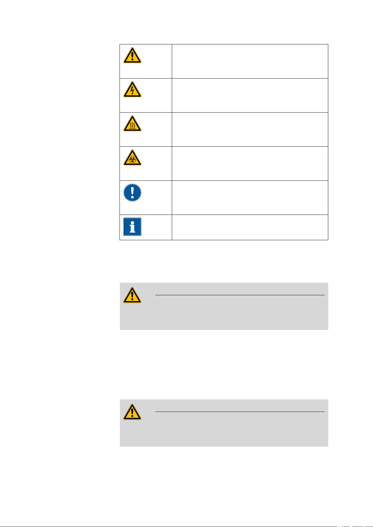
Warning
This symbol draws attention to a possible life hazard
or risk of injury.
Warning
This symbol draws attention to a possible hazard due
to electrical current.
Warning
This symbol draws attention to a possible hazard due
to heat or hot instrument parts.
Warning
This symbol draws attention to a possible biological
hazard.
Caution
This symbol draws attention to a possible damage of
instruments or instrument parts.
1.3 Safety instructions
1.3.1 General notes on safety
Warning
This instrument may only be operated in accordance with the specifications in this documentation.
This instrument has left the factory in a flawless state in terms of technical
safety. To maintain this state and ensure non-hazardous operation of the
instrument, the following instructions must be observed carefully.
1.3.2 Electrical safety
The electrical safety when working with the instrument is ensured as part
of the international standard IEC 61010.
Note
This symbol marks additional information and tips.
885 Compact Oven SC
Warning
Only personnel qualified by Metrohm are authorized to carry out service
work on electronic components.
■■■■■■■■
3
Page 14
1.3 Safety instructions
■■■■■■■■■■■■■■■■■■■■■■
Warning
Never open the housing of the instrument. The instrument could be
damaged by this. There is also a risk of serious injury if live components
are touched.
There are no parts inside the housing which can be serviced or replaced
by the user.
Mains voltage
Warning
An incorrect mains voltage can damage the instrument.
Only operate this instrument with a mains voltage specified for it (see
rear panel of the instrument).
Protection against electrostatic charges
Warning
Electronic components are sensitive to electrostatic charges and can be
destroyed by discharges.
Always pull the mains cable out of the mains connection socket before
connecting or disconnecting electrical appliances on the rear panel of
the instrument.
1.3.3 Tubing and capillary connections
Caution
Leaks in tubing and capillary connections are a safety risk. Tighten all
connections well by hand. Avoid applying excessive force to tubing
connections. Damaged tubing ends lead to leakage. Appropriate tools
can be used to loosen connections.
Check the connections regularly for leakage. If the instrument is used
mainly in unattended operation, then weekly inspections are mandatory.
■■■■■■■■
4
885 Compact Oven SC
Page 15

■■■■■■■■■■■■■■■■■■■■■■
1.3.4 Personnel safety
Wear protective goggles and working clothes suitable for laboratory
work while operating the 885 Compact Oven SC. It is also advisable to
wear gloves when caustic liquids are used or in situations where glass
vessels could break.
The oven module can exhibit temperatures of up to 250 °C. Sample
vessels and components of the sample rack can also become so hot
(<60 °C), that the skin could suffer burns in the event of contact.
Never touch the rack, sample vessels or oven when the heating is
turned on. Be aware of the current value on the temperature display.
1 Introduction
Warning
Warning
Wear working gloves.
Do not fail to switch off the device before attempting to clean it and
wait until the oven has cooled down.
Warning
Always install the safety shield supplied with the equipment before
using the instrument for the first time. Pre-installed safety shields are
not allowed to be removed.
The 885 Compact Oven SC may not be operated without a safety
shield!
Warning
Personnel are not permitted to reach into the working area of the
instrument while operations are running!
A considerable risk of injury exists for the user.
885 Compact Oven SC
■■■■■■■■
5
Page 16
1.3 Safety instructions
Warning
In the event of a possible jamming of a drive, the mains plug must be
pulled out of the socket immediately. Do not attempt to free jammed
sample vessels or other parts while the instrument is switched on. A
jamming can only be cleared when the instrument is in a voltage-free
status; this action generally involves a considerable risk of injury.
Warning
The 885 Compact Oven SC is not suitable for usage in biochemical,
biological or medical environments in its basic equipment version.
Appropriate protective measures must be implemented in the event
that potentially infectious samples or reagents are being processed.
1.3.5 Flammable solvents and chemicals
■■■■■■■■■■■■■■■■■■■■■■
Warning
All relevant safety measures are to be observed when working with
flammable solvents and chemicals.
■ Set up the instrument in a well-ventilated location.
■ Keep all sources of flame far from the workplace.
■ Clean up spilled liquids and solids immediately.
■ Follow the safety instructions of the chemical manufacturer.
1.3.6 Recycling and disposal
This product is covered by European Directive 2002/96/EC, WEEE – Waste
from Electrical and Electronic Equipment.
The correct disposal of your old equipment will help to prevent negative
effects on the environment and public health.
More details about the disposal of your old equipment can be obtained
from your local authorities, from waste disposal companies or from your
local dealer.
■■■■■■■■
6
885 Compact Oven SC
Page 17
■■■■■■■■■■■■■■■■■■■■■■
1
2
3
4
5
6
7
8
9
10
11
12
13
14
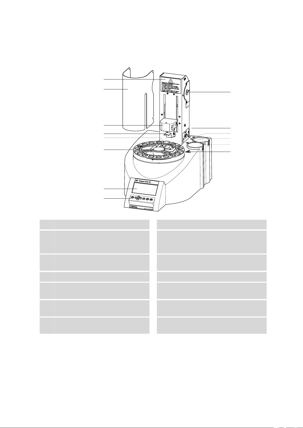
2 Overview of the instrument
2 Overview of the instrument
Warning instruction
1
Lift with distributor
3
Conditioning position
5
For a conditioning vial.
Display
7
Air pump inlet
9
With 6.2724.010 dust filter.
Gas outlet
11
For the tubing for testing. With M6 thread.
Recesses in the housing
13
For the drying flasks.
Safety shield (6.2751.170)
2
Deflector sheet
4
For deflecting the vial while the lift is traveling upwards.
Sample rack
6
For 17 samples.
Keypad
8
Instruction sign
10
Displays the tubing of the drying flasks.
Gas connections
12
For the drying flasks. With M6 thread.
Warning symbol
14
Warns against hot surfaces.
885 Compact Oven SC
■■■■■■■■
7
Page 18
■■■■■■■■■■■■■■■■■■■■■■
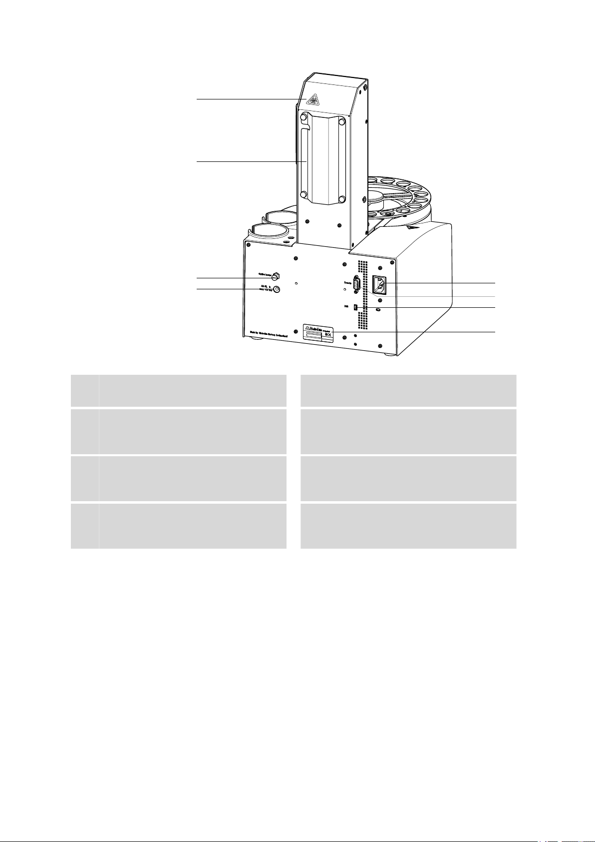
1
2
3
4
5
6
7
8
Warning symbol
1
See page 5
Outlet heater connection
3
For the heating tubing.
Mains connection socket
5
USB (OTG) connector
7
For connecting printers, USB sticks, USB
hubs, etc.
Tubing and cable cover
2
Air/nitrogen connector
4
With M6 inner thread. Inlet for external gassing.
Remote connector
6
For connecting instruments with a remote
interface. D-Sub, 9-pin.
Type plate
8
Contains specifications concerning mains
voltage and serial number.
■■■■■■■■
8
885 Compact Oven SC
Page 19

■■■■■■■■■■■■■■■■■■■■■■
3 Installation
3.1 Setting up the instrument
3.1.1 Packaging
The instrument is supplied in highly protective special packaging together
with the separately packed accessories. Keep this packaging, as only this
ensures safe transportation of the instrument.
3.1.2 Checks
Immediately after receipt, check whether the shipment has arrived complete and without damage by comparing it with the delivery note.
3.1.3 Location
The instrument has been developed for operation indoors and may not be
used in explosive environments.
3 Installation
Place the instrument in a location of the laboratory which is suitable for
operation, free of vibrations, protected from corrosive atmosphere, and
contamination by chemicals.
The instrument should be protected against excessive temperature fluctuations and direct sunlight.
3.2 Mounting the stand plate
The titration cell must be fitted as close to the device as possible. Two
stand plates (6.2001.050 and 6.2001.060) with support rods are available
for this purpose, each of which is supplied with a KF titrator.
885 Compact Oven SC
■■■■■■■■
9
Page 20

3.3 Removing the safety shield
1
2
3
6.2001.060 6.2001.050
6.2016.030
1
1
2
■■■■■■■■■■■■■■■■■■■■■■
Figure 1 Mounting the stand plate
Proceed as follows:
Screw the stand plate to the base of the 885 Compact Oven SC with
1
the screws provided, see figure.
Guide the large cylinder screw into the opening of the stand plate
2
from the bottom.
Screw the 6.2016.030 support rod tight on the cylinder screw. Fas-
3
ten in place with a hexagon key.
3.3 Removing the safety shield
Figure 2 Removing the coverings
■■■■■■■■
10
885 Compact Oven SC
Page 21

■■■■■■■■■■■■■■■■■■■■■■
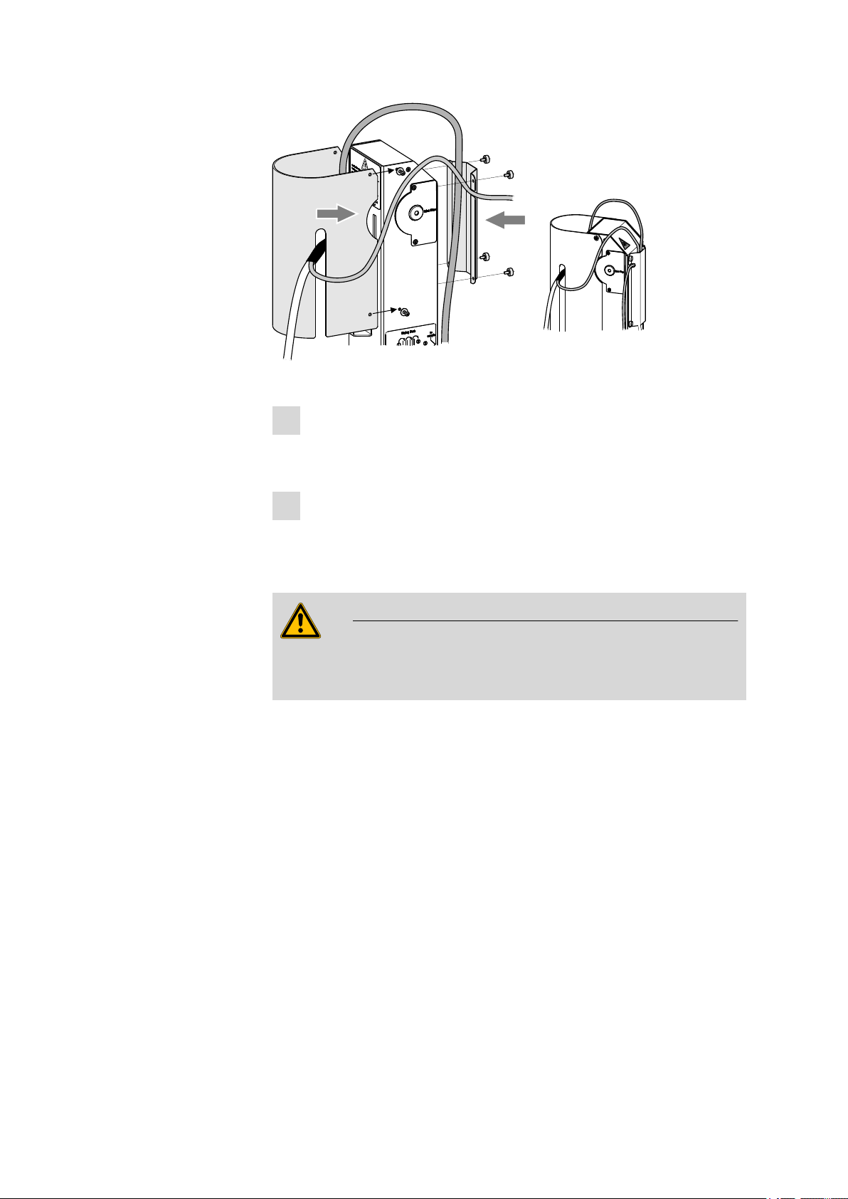
If you remove the safety shield before, the installation of the accessories is
easier to carry out. Proceed as follows:
Loosen the hexagon screws on the sides of the tower and remove
1
the safety shield.
Loosen the knurled screws on the rear of the tower and remove the
2
cable cover.
Do not forget to refasten the safety shields after the installation of the
accessories.
3.4 Mounting the needles
The length of the needle holder defines how deeply the piercing needle
penetrates the sample vessel.
If there is a danger that the heated sample could clog the needle, then
use the 6.2049.050 needle holder which is 73 mm in length. In this
case the piercing needle penetrates the sample vessel only slightly deeper
than the exhaust air needle and has no contact with the sample itself.
3 Installation
Caution
Movement with the needle holder 6.2049.050 may not extend more
deeply than up to Lift position 78 mm.
The 6.2049.040 needle holder, which is 58 mm in length, ensures that
the needle penetrates the liquid or powdery sample. The carrier gas can
flow through the sample and effect an efficient expulsion of the moisture
it contains. The 6.2049.040 needle holder can be ordered from Metrohm
if required.
885 Compact Oven SC
■■■■■■■■
11
Page 22
3.4 Mounting the needles
1
4
2
3
6.1805.060
6.2049.050
6.2816.080
6.2816.070
■■■■■■■■■■■■■■■■■■■■■■
Figure 3 Mounting the needles
Mount the needles as follows:
Screw the 6.2049.050 needle holder into the distributor on the
1
guide head.
Screw the 6.2816.080 exhaust air needle onto the Luer connec-
2
tor of the needle holder.
Carefully guide the 6.2816.070 piercing needle into the opening
3
of the distributor from above and allow it to drop down.
■■■■■■■■
12
Note
Take care to ensure that the white PTFE seal is positioned securely
on the needle.
Screw the 6.1805.060 FEP tubing by hand onto the opening of
4
the distributor.
Tightly screw the other end of the tubing to the gas outlet opening
5
(labeled with to sample) next to the tower, see figure.
885 Compact Oven SC
Page 23
■■■■■■■■■■■■■■■■■■■■■■
1
2
3
6.1608.050
6.1821.040
6.1602.145
6.2811.000
Figure 4 Connecting the tubing to the gas outlet
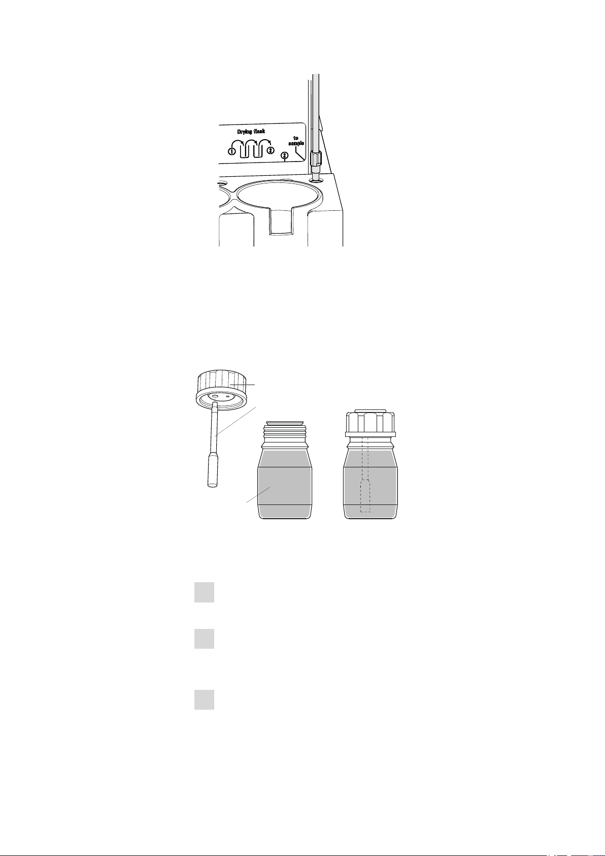
3.5 Assembling the drying flasks
Two drying flasks with desiccant are integrated into the gas flow in order
to dry the gas that is conveyed. Dust (e.g. from the desiccant) must be
prevented from finding its way into the sample vessel.
3 Installation
885 Compact Oven SC
Figure 5 Preparing the drying flasks
Prepare both drying flasks as follows:
Fill both 6.1608.050 drying flasks with 6.2811.000 molecular
1
sieve.
Screw one 6.1821.040 filter tube into each of the 6.1602.145
2
drying flask covers from below. Tighten the filter tubes well by
hand.
Screw the two drying flask covers with the filter tubes onto the dry-
3
ing flasks. Tighten the covers well by hand.
■■■■■■■■
13
Page 24
3.5 Assembling the drying flasks
1
2
2
3
3
4
1
6.1805.080
6.1805.080
6.1805.010
■■■■■■■■■■■■■■■■■■■■■■
Note
If drying flask covers or filter tubes are not sufficiently tightly
screwed on, then this will prevent a precise, regular gas flow. The
error message "Flow rate error" will appear as a rule when there
are leaks in the threaded connections.
■■■■■■■■
14
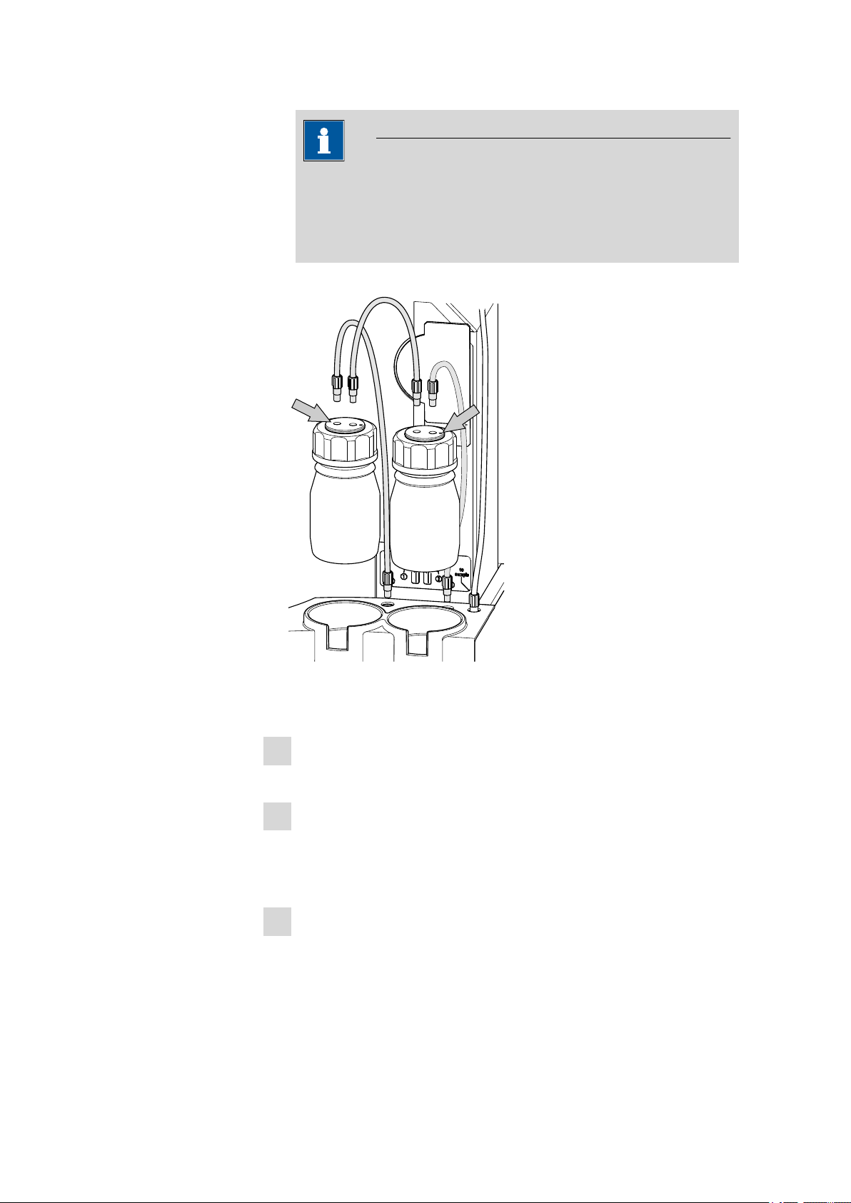
Figure 6 Mounting drying flasks and tubings
Mount the FEP tubings as follows:
Insert the two drying flasks that have been prepared into the holders,
1
see figure.
Screw one 6.1805.080 FEP tubing (25 cm in length) to the gas outlet
2
(at the rear on the left, labeled 1). Screw the other tubing end on the
front drying flask to the M6 connector without point marking (see
left-hand arrow).
Screw the second 6.1805.080 FEP tubing (25 cm in length) to the
3
gas inlet (at the rear on the right, labeled 2). Screw the other tubing
end on the rear drying flask to the M6 connector with point marking
(see right-hand arrow).
885 Compact Oven SC
Page 25
■■■■■■■■■■■■■■■■■■■■■■
6.2043.005
6.1830.030
3 Installation
Screw the 6.1805.010 FEP tubing (13 cm in length) tightly onto the
4
remaining M6 connectors of the drying flasks.
The figure Drying flask on the right-hand side of the instrument displays the diagram for the tubing.
Note
Tighten the screw connections well by hand.
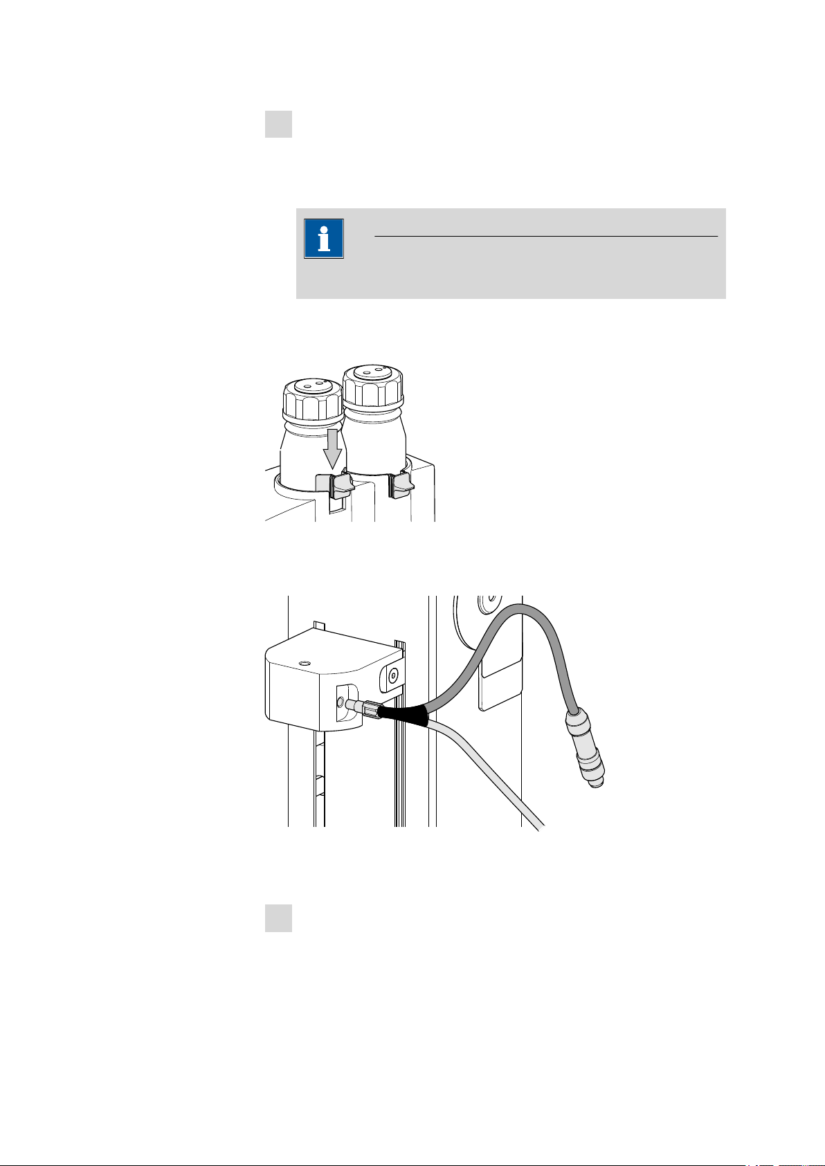
You can fasten the drying flasks with the 6.2043.005 holding clamps, see
figure.
3.6 Mounting the heating tubing
Figure 7 Mounting the heating tubing
Proceed as follows:
Screw the M6 connector of the 6.1830.030 heating tubing into
1
the side opening of the distributor on the guide head.
885 Compact Oven SC
■■■■■■■■
15
Page 26
3.7 Mounting the safety shield
■■■■■■■■■■■■■■■■■■■■■■
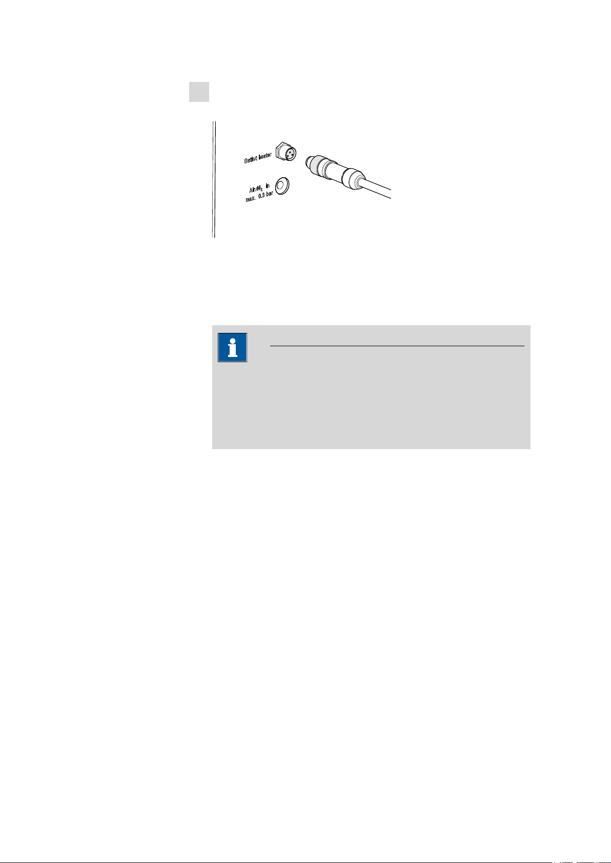
Connect the heating tubing cable to the Outlet heater connector
2
on the rear of the instrument.
Figure 8 Connecting the heating tubing
Rotate the plug in such a way that the three contact pins match the
alignment of the corresponding openings on the socket. Press the
plug against the socket and rotate the front knurled screw in a clockwise direction.
Note
The heating jacket of the heating tubing is heated up to approx.
40…50 °C as soon as the instrument is switched on. This prevents
the condensation of moisture in the tubing when this is expelled
from the sample and transferred with the aid of a carrier gas into a
KF titration cell.
3.7 Mounting the safety shield
Now you can remount the safety shield. Proceed as follows:
■■■■■■■■
16
885 Compact Oven SC
Page 27
■■■■■■■■■■■■■■■■■■■■■■
1
1
2
2
Figure 9 Mounting the coverings
Fasten the safety shield with the four hexagon screws to the sides of
1
the tower. The heating tubing and its connection cable must be guided through the slot of the cover.
Fasten the cable cover with the four knurled screws to the rear side
2
of the tower. The gas supply tubing must be guided underneath the
cover. The connection cable of the heating tubing must be guided
through the lateral recess of the cover, see figure.
3 Installation
Warning
The 885 Compact Oven SC may not be operated without a safety
shield!
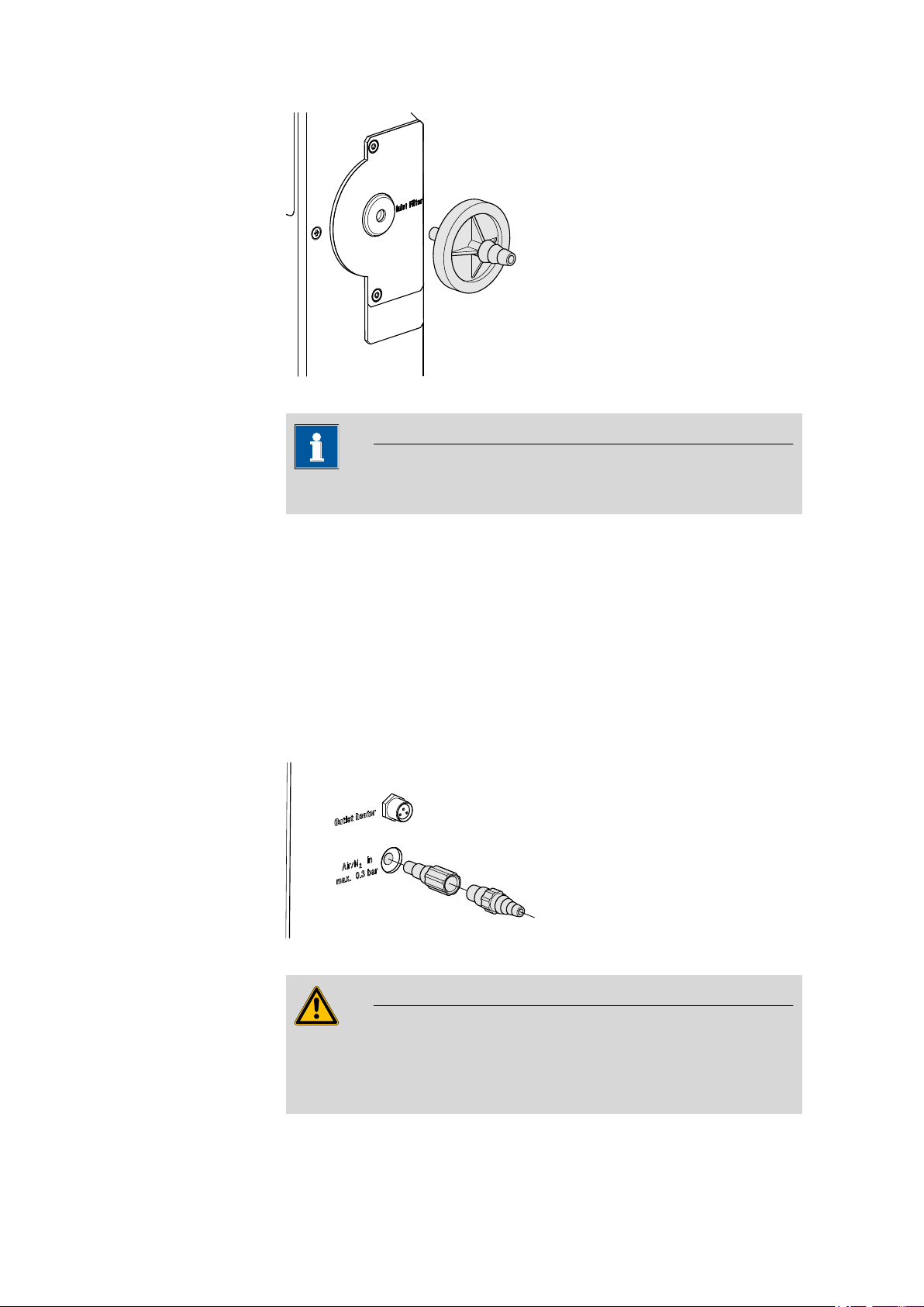
3.8 Mounting the dust filter
The built-in air pump must be protected against dust. A 6.2724.010
dust filter must be placed on the air inlet (Inlet filter) on the right-hand
side of the housing for this reason.
885 Compact Oven SC
■■■■■■■■
17
Page 28
3.9 Assembling the air/nitrogen connector
6.2724.010
6.1808.050
6.1808.040
Figure 10 Mounting the dust filter
The dust filter should be replaced once a year.
■■■■■■■■■■■■■■■■■■■■■■
Note
3.9 Assembling the air/nitrogen connector
If compressed air, nitrogen or another gas is to be used for transferring
the expelled moisture, then a separate connector is available on the rear
of the instrument.
A tubing with M6 thread can be connected directly to the connector Air/
N2 in. Enclosed with the instrument is the 6.1808.040 M6/M8 tubing
adapter for a tubing with an M8 thread. The 6.1808.050 M8/tubing
olive can also be put in place in order to connect a simple tubing.
Figure 11 External gas supply connection
Warning
■■■■■■■■
18
If gas is supplied from a pressure line or a pressure vessel, then it is
imperative that a pressure reduction valve be placed upstream. The gas
pressure may not exceed a maximum overpressure level of 0.3 bar.
885 Compact Oven SC
Page 29

■■■■■■■■■■■■■■■■■■■■■■
6.1830.030
6.1446.170
1
2
3
3 Installation
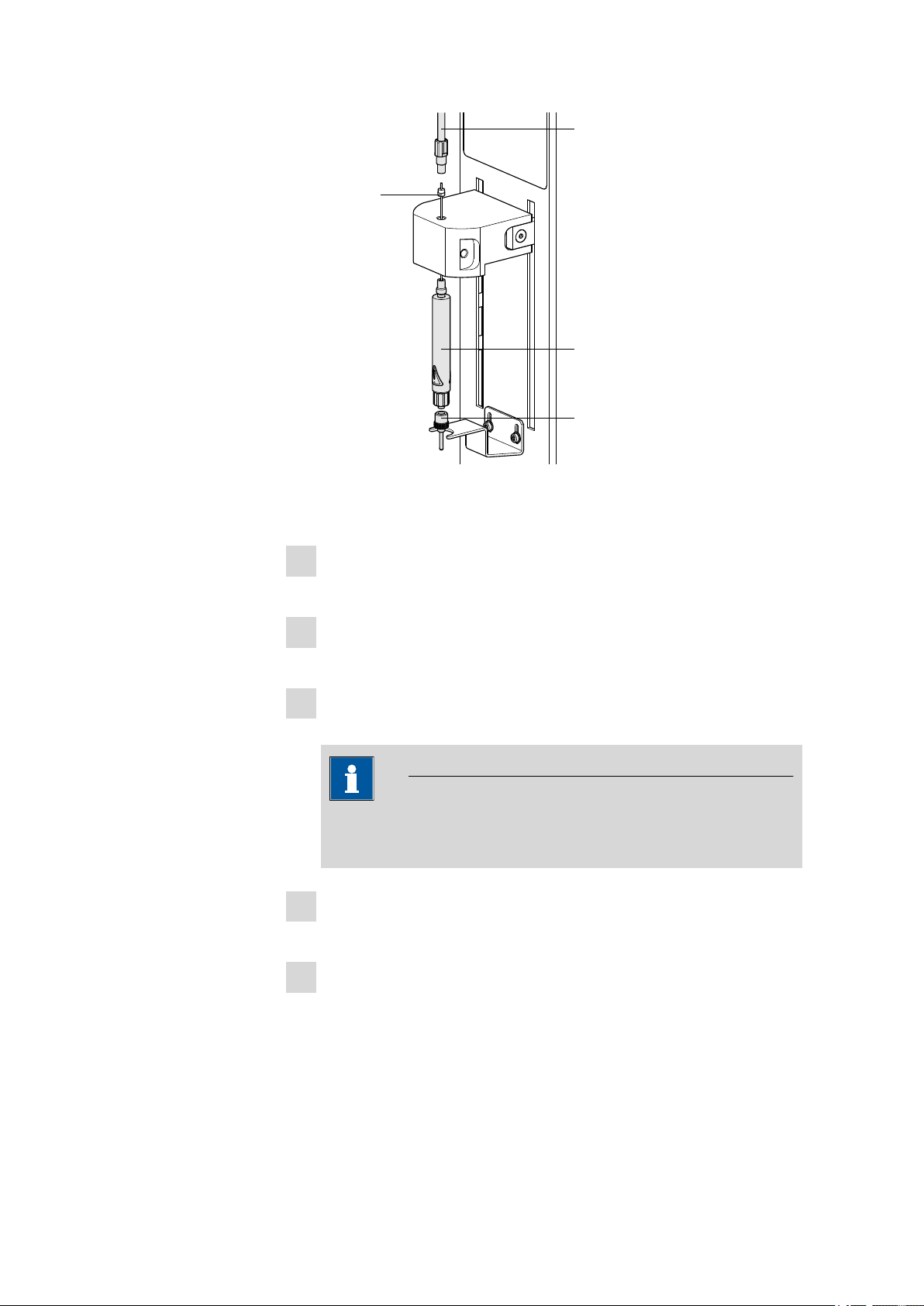
3.10 Inserting the heating tube into the KF titration cell
The 885 Compact Oven SC can be used in combination with a KF coulometer or a volumetric KF titrator. The mounting of the tip of the heating
tube is accomplished in different ways for the respective KF titration cells.
Coulometric KF titration cell
■ Remove the protective cover from the tip of the heating tube and the
E.3010.032 O-ring.
■ Disassemble the accompanying 6.1446.170 heating tube stopper
into three parts.
885 Compact Oven SC
Figure 12 Coulometric KF titration cell
Proceed as follows:
Guide the upper part of the heating tube stopper over the tip of the
1
6.1830.030 heating tube as shown in the illustration.
Guide the O-ring of the heating tube stopper over the heating tube.
2
Guide the lower part of the heating tube stopper over the heating
3
tube and screw the three parts together (not too tightly).
Insert the stopper with the tip of the heating tube into one of the
4
two SGJ openings of the KF titration cell
■■■■■■■■
19
Page 30

3.10 Inserting the heating tube into the KF titration cell
6.1830.030
E.3010.032
6.2730.020
1
2
3
Shift the tip vertically in such a way that the outlet opening of the
5
tubing is immersed as deeply as possible. The tip must not however
be permitted to get in the way of the stirring bar in the KF titration
cell. Afterwards give the heating tube stopper its final tightening.
Volumetric KF titration cell
■ Remove the protective cover from the tip of the heating tube and the
E.3010.032 O-ring. The latter you will still need.
■ A 6.2730.020 septum stopper is enclosed with every KF titrator
made by Metrohm. Disassemble this septum stopper into three parts
and remove the septum. It will not be required.
■■■■■■■■■■■■■■■■■■■■■■
■■■■■■■■
20
Figure 13 Volumetric KF titration cell
Proceed as follows:
1
2
3
4
Guide the upper part of the septum stopper over the tip of the
6.1830.030 heating tube as shown in the illustration.
Guide the E.3010.032 O-ring over the heating tube.
This O-ring is also part of the 6.1244.040 set of seals that is enclosed
with each KF titrator. It cannot be reordered individually.
Guide the lower part of the septum stopper over the heating tube
and screw the three parts together (not too tightly).
Insert the stopper with the tip of the heating tube into the front
opening of the KF titration cell
885 Compact Oven SC
Page 31

■■■■■■■■■■■■■■■■■■■■■■
Shift the height of the tip of the heating tube vertically in such a way
5
that the outlet opening of the tubing is immersed as deeply as possible. The tip must not however be permitted to get in the way of the
stirring bar in the KF titration cell. Afterwards give the septum stopper its final tightening.
3.11 Remote connections
The 885 Compact Oven SC can be used as a control device for a simple
automation system with a large variety of different instruments. Even
older Metrohm instruments can thus be integrated into an automated
analysis system.
3.11.1 Remote cable
The following connecting cable can be used with the 885 Compact Oven
SC:
3 Installation
6.2141.340 (9-pin/
25-pin)
■ For connections with a 756/831 coulometer, a 7xx Titrino or a Titrando
by means of a Remote Box 6.2148.010.
The cable transmits start and stop signals from the 885 Compact Oven SC
to the connected titrator and status signals (Cond OK, EOD) from the titrator to the 885 Compact Oven SC.
3.11.2 Example systems
The following illustrations show typical automation systems with different
instrument combinations.
885 — 756/831 Coulometer/7xx Titrino
The standard combination for water determinations with a 7xx Coulometer or a 7xx KF Titrino.
885 Compact Oven SC
■■■■■■■■
21
Page 32

3.11 Remote connections
6.2141.340
885 Compact Oven SC
756/831 Coulometer
6.2148.010
Remote Box
851/852 Titrando
885 Compact Oven SC
Touch Control
6.2141.340
■■■■■■■■■■■■■■■■■■■■■■
Figure 14 Remote connection 885 Compact Oven SC - Coulometer or
7xx KF Titrino
The titrator is operated in the KFC or KF mode. The sample series is started
on the 885 Compact Oven SC
885 — 851 Titrando
The standard combination for water determinations with a Titrando and a
Touch Control.
■■■■■■■■
22
Figure 15 Remote connection 885 Compact Oven SC - Remote Box -
851/852 Titrando
The Titrando is operated in KFC mode. The sample series is started on the
885 Compact Oven SC.
885 Compact Oven SC
Page 33

■■■■■■■■■■■■■■■■■■■■■■
6.2151.100
3 Installation
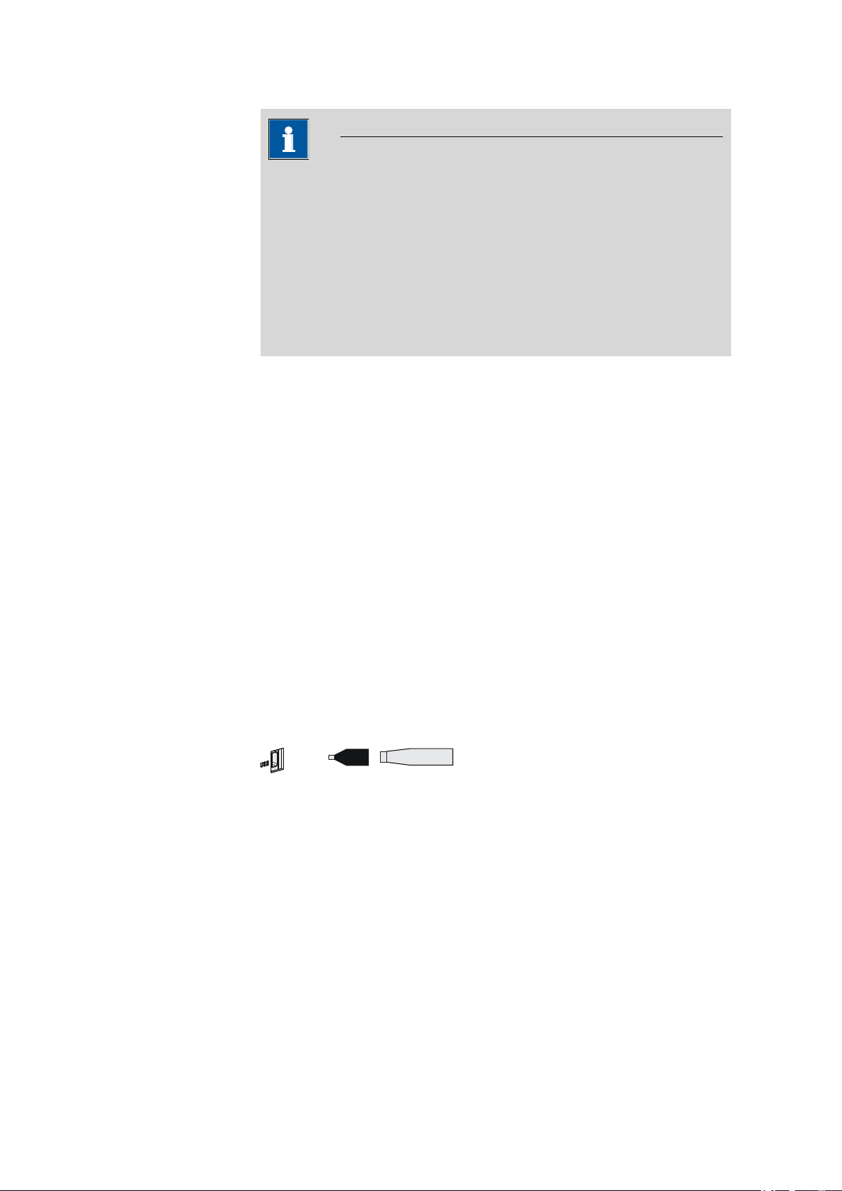
3.12 Connecting a keyboard, printer and other USB devices
The 885 Compact Oven SC has a USB (OTG) connector. Use the provided
6.2151.100 adapter USB MINI (OTG) - USB A for connecting USB devices
as e.g. printers, keyboards or USB sticks, see the following figure.
Figure 16 Connecting USB devices
Caution
Switch the instrument off before connecting or disconnecting a USB
device or a USB stick.
The 885 Compact Oven SC can only recognize the device immediately
after switching on.
The following devices can be operated directly on the USB connector
with the 6.2151.100 adapter:
■ USB sticks (for the backup or storing of methods)
■ 6.2147.000 numerical USB keypad
■ USB hub (with or without an own power supply)
The 6.2147.000 numerical USB keypad serves for comfortable numerical input and for navigating in the dialog. In addition, it provides two USB
connectors. Connect additional USB devices to the keypad.
885 Compact Oven SC
■■■■■■■■
23
Page 34
3.12 Connecting a keyboard, printer and other USB devices
USB MINI (OTG)-USB
USB stick
6.2151.100
Note
Most of the USB devices need a so-called hub in order to work correctly.
A USB hub is a distributor to which several USB devices can be connected. USB hubs are available in specialty stores in a number of different
models.
The USB (OTG) connector of the 885 Compact Oven SC has no such
hub. The 6.2147.000 numerical USB keypad has a USB hub and two
USB connectors.
The following devices can only be connected to a 6.2147.000
numerical keypad or to a USB hub:
■ Printer (with USB connector, use the 6.2151.020 connecting cable)
■ Barcode reader (with USB cable)
■ Mouse (PC mouse with USB cable, for navigating in the dialog)
■■■■■■■■■■■■■■■■■■■■■■
The following devices can only be connected to a USB hub:
■ PC keyboard (with USB cable, for the comfortable input of letters and
numbers)
■ Keypad with numerical keypad (with USB cable)
If you wish to connect several different instruments without own
power supply, then you must possibly use a USB hub with own power
supply (self powered). The USB (OTG) connector of the 885 Compact
Oven SC is not designed for supplying power to several devices with elevated electricity requirements.
Examples:
Figure 17 Connecting the USB stick
■■■■■■■■
24
885 Compact Oven SC
Page 35

■■■■■■■■■■■■■■■■■■■■■■
USB MINI (OTG)-USB
USB stick
Keypad
6.2147.000
6.2151.100
Printer
Figure 18 Connecting the 6.2147.000 USB keyboard with USB stick and
printer
3.13 Connecting the mains cable
Warning
This instrument must not be operated except with the mains voltage
specified for it (see rear of the instrument).
3 Installation
Protect the connection sockets against moisture.
Figure 19 Connecting the mains cable
885 Compact Oven SC
■■■■■■■■
25
Page 36

4.1 Execution sequences
4 Automation sequence
4.1 Execution sequences
This automation sequence is comprised of three sequences:
■ Start sequence
■ Sample sequence
■ End sequence
These sequences cannot be modified. However, the parameters which are
decisive for a determination can be set in order to match specific methods
(see Chapter 7.1, page 51).
Start sequence
This command sequence is run one time after the method has been started. It is used for conditioning the entire system.
■■■■■■■■■■■■■■■■■■■■■■
The oven is heated to the set temperature. The tubing system is rinsed
with the carrier gas until all moisture has been expelled. The moisture is
titrated in the titration cell.
The titrator is connected with the 885 Compact Oven SC by means of a
remote cable. The latter starts the conditioning on the titrator through a
control line in the remote cable. Once the titration cell is conditioned, the
titrator switches a signal line to active. This signal line is monitored by the
885 Compact Oven SC.
The following steps are carried out in sequence:
■ Move to the conditioning beaker
■ Lower lift, pierce vial
■ Switch on the gas flow
■ Start conditioning at the titrator
■ Heat the oven to the temperature set
■ Wait while conditioning
The signal line Cond OK must be active for 60 s.
Sample sequence
This command sequence is executed for every sample (or blank). It is
repeated for each sample.
■■■■■■■■
26
The total number of samples (or repetitions) and the rack position of the
first sample (or blank) are entered when the method is started.
The following steps are carried out in sequence:
■ Scan the Cond OK signal of the titrator
■ Switch off the gas flow
885 Compact Oven SC
Page 37

■■■■■■■■■■■■■■■■■■■■■■
4 Automation sequence
■ Move to the sample beaker
■ Lower lift, pierce vial, move vial into oven
■ Switch on the gas flow
■ Start the titration at the titrator
■ Record temperature and gas flow, wait for end of titration (EOD sig-
nal)
■ Print out the report (optional)
■ Switch off the gas flow
■ Move to the conditioning beaker
■ Lower lift, pierce vial
■ Switch on the gas flow
■ Wait while conditioning
The signal line Cond OK must be active for 60 s.
End sequence
This command sequence is run one time after the last sample sequence.
The parameter End of series can be used to control a slightly variant
behavior.
The following steps are carried out in sequence:
■ Switch off the gas flow
■ Move to the conditioning beaker, do not lower the lift
■ Stop titrator (only with End of series = Stop)
The titrator is not stopped with End of series = Conditioning, i.e.
the titration cell continues to be conditioned.
■ Switch off the oven heating
4.2 Oven heating
The target temperature of the oven is established as quickly as possible
with a high-performance heater and controlled by a reliable regulator. The
oven temperature is continuously corrected and maintained as precisely as
possible at the set value.
The display always shows the oven temperature, not the temperature
of the sample in the vessel. This can deviate from the oven temperature
by several °C, because the flowing carrier gas cools the sample.
Note
885 Compact Oven SC
The heating is switched on automatically when the device is switched on.
The oven will be heated to the temperature defined in the currently loaded method (see page 51).
■■■■■■■■
27
Page 38

5.1 Switching the instrument on and off
5 Operation
5.1 Switching the instrument on and off
Switching on the instrument
Proceed as follows:
■ Press the red [STOP] key.
1
The instrument is initialized and a system test performed. This
process takes some time.
The main dialog is displayed:
Switching off the instrument
The instrument is switched off with the [STOP] key. The fact that the key
needs to be pressed down for an extended time prevents accidental
switch off.
■■■■■■■■■■■■■■■■■■■■■■
Proceed as follows:
■ Keep the red [STOP] key pressed down for at least 3 s.
1
A progress bar is displayed. If the key is released during this time,
then the instrument will not be switched off.
5.2 Fundamentals of operation
5.2.1 The keypad
Figure 20 Keypad 885 Compact Oven SC
BACK Apply the input and exit the dialog.
⇧ ⇩ Move the selection bar either up or down by one
line at a time. Select the character to be entered
in the text editor.
■■■■■■■■
28
885 Compact Oven SC
Page 39

■■■■■■■■■■■■■■■■■■■■■■
⇦ ⇨ Select the character to be entered in the text and
number editor. Select the individual functions in
the function bar.
OK Confirm the selection.
STOP Stop an ongoing method run or a manual func-
tion. Switch the instrument on/off.
START Start a method run.
5.2.2 Structure of the dialog windows
The current dialog title is displayed on the left-hand side of the title line.
The current status of the system is displayed in the upper right-hand corner:
ready The instrument is in normal status.
busy A method has been started.
hold A method has been paused.
Some dialogs have a so-called function bar on the bottom line. The functions contained therein can be selected with the arrow keys [⇦] or [⇨]
and executed with [OK].
5 Operation
5.2.3 Navigating in the dialog
The selection bar is displayed in inverted style. Use the arrow keys [⇧] and
[⇩] to move the selection bar upward or downward one line at a time. If
a dialog text is marked with ">", then additional settings are available in
a subordinate dialog. Use [OK] to access this dialog.
Example: System settings
Use the [BACK] key to return to the next higher level.
5.2.4 Entering text and numbers
In the editing dialog for text or numerical input you can select the individual characters with the arrow keys. Use [OK] to apply the character in the
input field. The following functions are available:
885 Compact Oven SC
■■■■■■■■
29
Page 40

5.3 Methods
■■■■■■■■■■■■■■■■■■■■■■
Editing function Description
Accept
Cancel
Clear
[BACK]
The modification is applied and the editing dialog
is exited.
The editing dialog is exited without applying the
modification.
The content of the input field is deleted completely.
The character left of the cursor is deleted (backspace).
Text editor only
The cursor within the input field is shifted to the
left by one character each time that [OK] is
pressed.
Text editor only
The cursor within the input field is shifted to the
right by one character each time that [OK] is
pressed.
The modification is applied and the editing dialog
is exited.
The [BACK] key has the same function as Accept.
5.3 Methods
The 885 Compact Oven SC operates with a specified procedural method.
Various settings can be parameterized individually in the procedural
method, depending on application. An optimized method run can be
saved as a reusable method.
5.3.1 Creating a new method
Proceed as follows to create a new method:
1
Open the method table
■ In the main dialog, select Method and press [OK].
The method table opens:
■■■■■■■■
30
885 Compact Oven SC
Page 41

■■■■■■■■■■■■■■■■■■■■■■
2
Load an empty method template
■ Use the arrow keys to select New and press [OK].
The method template is now loaded and is displayed in the main dialog under Method.
If a new method has been created, then the individual parameters can be
modified under Menu ▶ Parameters.
5.3.2 Saving a method
If you modify method parameters, then you can save these as your own
method. A maximum of 100 methods can be saved.
5 Operation
To save a method, proceed as follows:
1
Open the method table
■ In the main dialog, select Method and press [OK].
The method table opens:
885 Compact Oven SC
■■■■■■■■
31
Page 42

5.3 Methods
■■■■■■■■■■■■■■■■■■■■■■
2
Modify/apply the method name
■ In the function bar, select Store and press [OK].
A method name will be suggested for new methods. If the
method has already been saved once, then the method name will
be displayed:
Apply the name:
■ Press [BACK].
The method will be saved and the method table is displayed.
Enter a new name:
■ Press [OK].
The text editor opens.
■ Enter a method name (max. 12 characters) and apply with
Accept or [BACK].
■ Press [BACK].
The method will be saved and the method table is displayed.
5.3.3 Loading a method
To load a method, proceed as follows:
1
Open the method table
■ In the main dialog, select Method and press [OK].
The method table with the stored methods opens:
■■■■■■■■
32
2
Select a method
■ Select the desired method.
885 Compact Oven SC
Page 43
■■■■■■■■■■■■■■■■■■■■■■
3
Load the method
■ In the function bar, select Load and press [OK].
The method is now loaded and is displayed in the main dialog under
Method.
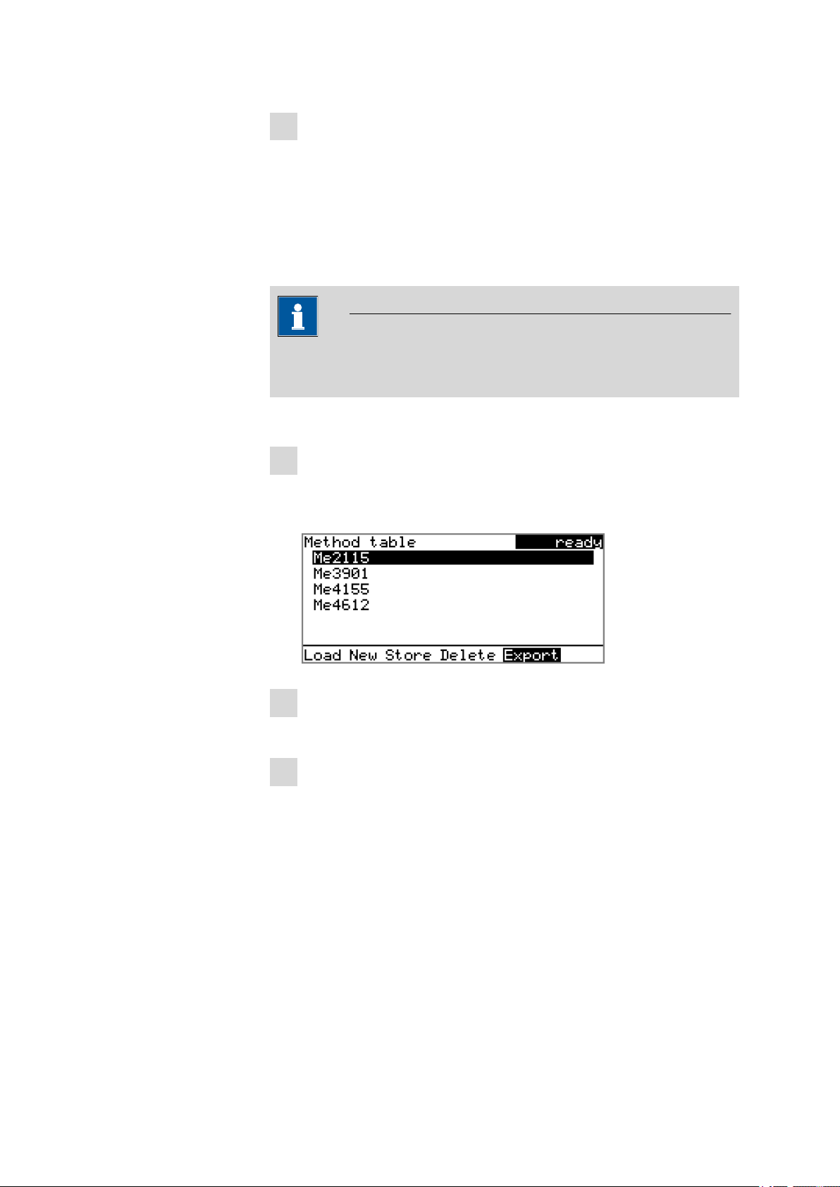
5.3.4 Exporting a method
The methods can be exported on a connected USB stick.
This function is possible only if a USB stick is connected as an external
storage medium.
To export a method, proceed as follows:
1
Open the method table
■ In the main dialog, select Method and press [OK].
5 Operation
Note
The method table with the stored methods opens:
2
Select a method
■ Select the desired method.
3
Export the method
■ In the function bar, select Export and press [OK].
The method is being exported. The directory structure on the USB
stick is listed in chapter 6.2, page 44.
885 Compact Oven SC
■■■■■■■■
33
Page 44

5.4 Performing a sample series
5.4 Performing a sample series
Blanks should always be at the first sample position so that the blank values determined are available with every sample processing.
5.4.1 Starting the sample series
Starting a sample series
A suitable method must be loaded before a sample series is started (see
Chapter 5.3.3, page 32). The necessary parameters ) can then be modi-
fied.
1
Define the sample series
Press the [START] key.
You can now enter the quantity and the first rack position of the
samples to be processed.
2
Enter the number of samples
■ Select Number of samples and press [OK].
■ Enter the number of samples including the blanks.
■ Close the input dialog with [BACK] or Accept.
■■■■■■■■■■■■■■■■■■■■■■
Note
Take care to ensure that the number of samples matches the number of sample data entered in the titrator.
3
Enter the rack position of the first sample
■ Select Next sample pos. and press [OK].
■ Enter the starting position of the sample series.
■ Close the input dialog with [BACK] or Accept.
The value for the number of samples remains saved for the next sample series. The position of the first sample is increased with each
method run.
You can still cancel the start of the sample series at this time with
[BACK] or [STOP].
4
Close the sample series dialog
Close the dialog with the [BACK] key.
■■■■■■■■
34
885 Compact Oven SC
Page 45

■■■■■■■■■■■■■■■■■■■■■■
Stopping a sample series
A sample series can be canceled at any time.
Press the [STOP] key.
1
The method run is stopped. The sample series cannot be resumed.
5.4.2 Pausing a sample series and continuing
Pausing a sample series
A method run of the 885 Compact Oven SC can be paused and then continued again. The connected instruments are however not paused.
Note
Interruption of the method run is not possible during the execution of
commands during which the 885 Compact Oven SC waits for a signal
from the connected titrator. This is the case during the conditioning of
the titration cell and the execution of the KF titration.
5 Operation
A function bar with the entry "Hold" is displayed during the run of a sample series in the so-called "Live" dialog.
Press the [OK] key.
1
The method run is paused. However, currently running movements
of the sample rack or the lift will be finished.
Instead of the "Hold" function, "Continue" is displayed in the function bar.
Continuing sample series
If a method run is paused, then the "Hold" status is displayed in the title
bar, see previous figure. The sequence can be continued with the "Con-
tinue" function.
In the "Hold" status, a method run can be stopped completely, and with
it the entire sample series, by pressing the [STOP] key.
Press the [OK] key.
1
As is also the case at the start of a sample series, a request dialog
appears here in which the number of samples to be processed can
885 Compact Oven SC
■■■■■■■■
35
Page 46

5.5 Printing a report manually
still be changed. It is thus possible to shorten a sample series or to
extend it, without stopping it.
Press the [OK] key and enter the number of samples that still need to
2
be processed. The current sample must be taken into account.
Press the [START] key.
3
The sample series continues.
5.5 Printing a report manually
■■■■■■■■■■■■■■■■■■■■■■
Menu ▶ Print reports
To print a report manually, proceed as follows:
1
Open the main menu
■ In the main dialog, select Menu and press [OK].
2
Open the print dialog
■ Select the menu item Print reports and press [OK].
The dialog window with the available reports opens:
■■■■■■■■
36
885 Compact Oven SC
Page 47

■■■■■■■■■■■■■■■■■■■■■■
5 Operation
3
Select a report
■ Select the desired report and press [OK].
The report is being printed out.
The following reports can be printed out manually:
Results Result report with temperatures and gas flows
etc.
Parameters Report with all method parameters of the loaded
method.
System System report with system settings, solution list,
external devices, etc.
PC/LIMS Machine-readable report with all of the data for
a determination. This report can be saved as a
TXT file on a connected USB stick or sent to a
terminal program or to a LIMS via an RS-232
interface. The definition is made in the system
settings (see "PC/LIMS report", page 47).
Report as in
method
5.6 Manual control
Menu ▶ Manual control
The following functions are available in the manual control:
■ Rotating the sample rack (Rack position)
■ Moving the lift (Lift position)
■ Switching the oven on/off (Oven)
■ Setting the temperature (Temperature)
■ Switching the gas flow on/off (Gas flow)
■ Setting the flow rate (Flow rate)
The available subfunctions are listed for each function in the function bar.
5.6.1 Rotating the sample rack
The reports that are defined in the method will
be printed out.
885 Compact Oven SC
■■■■■■■■
37
Page 48

5.6 Manual control
■■■■■■■■■■■■■■■■■■■■■■
If the Rack position line is selected, then the arrow keys [⇨] and [⇦] can
be used to select one of the following functions, which can then be run
by pressing [OK]:
Next The lift is moved upward and the next-higher
rack position is placed in front of the lift.
If the [OK] key remains pressed, the rack automatically moves to the next position.
Previous The lift is moved upward and the next-lower
rack position is placed in front of the lift.
If the [OK] key remains pressed, the rack automatically moves to the next position.
Reset The rack is initialized. The lift is moved upward
and the sample rack is rotated to the starting
position. At the same time, the starting position
(Next sample pos.) is reset to 1 for the start of
the next sample series.
The rack position display is always updated as soon as the rack is in the
new position.
5.6.2 Moving the lift
If the Lift position line is selected, then the lift can be moved to the position suggested in the function bar by pressing [OK]. Only two positions
are possible:
Work pos. The working height. It can be set under
Shift pos. The rotating height. The lift moves all the way to
The current lift position is displayed. The respective other possible position
is offered in the function bar.
Menu ▶ System ▶ Lift .
the top.
■■■■■■■■
38
885 Compact Oven SC
Page 49

■■■■■■■■■■■■■■■■■■■■■■
5.6.3 Switching the oven on/off
If the line Oven is selected, then oven heating can be switched off and on
again with the [OK] key.
5.6.4 Entering the oven temperature
5 Operation
If the line Temperature is selected, then a temperature value can be
entered with [OK].
Temperature
Setpoint value for the oven heating.
Range
Default value
50 ... 250 °C (Increment: 1)
100 °C
5.6.5 Switching the gas flow on/off
If the line Gas flow is selected, then the gas flow can be switched on and
off again with the [OK] key.
The question of whether the installed pump or the valve for the gas supply
connection (Air/N2 in) is switched on depends on whether, under Param-
eters (method-specific), the Gas supply is set to pump or valve.
885 Compact Oven SC
■■■■■■■■
39
Page 50

5.6 Manual control
5.6.6 Entering the flow rate
If the line Gas flow is selected, then a value for the flow rate of the gas
can be entered with [OK].
Gas flow
Default value for the gas flow.
■■■■■■■■■■■■■■■■■■■■■■
Range
Default value
10 ... 150 mL/min (Increment: 1)
50 mL/min
■■■■■■■■
40
885 Compact Oven SC
Page 51

■■■■■■■■■■■■■■■■■■■■■■
6 System settings
6.1 Basic settings
Menu ▶ System ▶ Settings
This chapter contains a description of general instrument settings.
User name
A user name can be entered here for the report. This parameter will only
be printed if a user has been defined.
6 System settings
Instrument name
Serial number
Program version
Time
Input
Default value
An instrument name can be entered here for the report. This parameter
will only be printed if a designation has been defined.
Input
Default value
Serial number of the instrument. This is printed as a component of the
instrument identification in the report header.
Version number of the instrument software. This is printed as a component of the instrument identification in the report header.
Current time. Only valid numbers can be entered.
Format: hh:mm:ss
max. 12 characters
empty
max. 10 characters
empty
Date
Language
885 Compact Oven SC
Current date. Only valid numbers can be entered.
Format: YYYY:MM:DD
Setting the dialog language. In addition to English one further language
can be selected.
■■■■■■■■
41
Page 52

6.1 Basic settings
Dialog type
■■■■■■■■■■■■■■■■■■■■■■
Note
A second language must be installed in advance in order to be able to
select it here. The installation may only be carried out by competent
personnel.
The user dialog can be limited for routine operations. One can operate
normally with methods in the limited dialog. However, no settings can be
made or methods deleted.
The resetting of the dialog does not take effect until the main menu is exited.
The limitation of the dialog has the following effects:
■ The menu items System and Parameters are not shown in the main
menu.
■ Methods can only be loaded, but not deleted, exported or created.
Note
If the limited dialog is activated for routine operations, then the expert
dialog cannot be switched on during running operations. To change
the dialog type, the 885 Compact Oven SC must be switched off and
then back on again. The expert dialog can be forced at the time the
instrument is started. Then it is possible to enter whatever settings one
wishes, e.g. the changing of the dialog type. If the instrument is
switched off again without changing the dialog type, then the routine
dialog will remain activated.
Forcing the expert dialog:
■ Switch on the instrument.
■ Wait for the display of the instrument logo with the lettering easy,
safe, precise.
■ Press the [STOP] key once again and hold it down while also briefly
pressing the [BACK] key.
■ Release both keys once again.
Selection
Default value
Expert | Routine
Expert
■■■■■■■■
42
Expert
Complete dialog.
Routine
Limited dialog for routine operations.
885 Compact Oven SC
Page 53

■■■■■■■■■■■■■■■■■■■■■■
Contrast
6 System settings
The contrast of the display can be adjusted with the arrow keys [⇦] and
[⇨].
■ [⇦]: the contrast will be decreased by one step each time the key is
pressed.
■ [⇨]: the contrast will be increased by one step each time the key is
pressed.
Beep
Range
Default value
150 ... 240
212
Note
Alternatively, the contrast can also be modified in the following manner:
Keep the red [STOP] key pressed down. As soon as the progress bar
appears, also press the arrow key [⇩] or [⇧] repeatedly.
This method will however cause the contrast to be modified by several
steps.
If this parameter is activated, then a short beep will be heard in the following cases:
■ When a key is pressed.
■ At the end of the determination.
Selection
Default value
on | off
on
885 Compact Oven SC
■■■■■■■■
43
Page 54

6.2 File management
6.2 File management
Menu ▶ System ▶ File management
Note
This menu item is visible only when a USB stick has been connected as
an external storage medium.
Methods can be imported and deleted from a USB stick in this dialog.
Only methods located in the Files directory are displayed in the list (see
"Directory structure on the USB stick", page 44).
A backup can be made of the system (all data and settings). Similarly, an
existing backup can be reloaded.
Import
Import the selected method.
■■■■■■■■■■■■■■■■■■■■■■
Delete
Backup
Restore
Delete the selected method.
Create a backup of all data and settings on the USB stick.
Note
Only one backup can be created on the same USB stick.
If a backup has already been stored on the stick, then it will be overwritten when this function is carried out again.
Load the backup from a connected USB stick.
Directory structure on the USB stick
A directory with the instrument number is generated on the USB stick. The
structure within the directory appears as follows:
■■■■■■■■
44
Figure 21 Directory structure on the USB stick
885 Compact Oven SC
Page 55

■■■■■■■■■■■■■■■■■■■■■■
Backup All of the files of the backup are stored in this
Files Exported methods will be stored in this directory.
pc_lims_report PC/LIMS reports are stored in this directory as
6.3 Oven settings (heater)
Menu ▶ System ▶ Heater
6 System settings
directory. The directory will be created the first
time a backup is created.
The directory will be created the first time a
method is exported.
Only methods being located in this directory can
be imported.
TXT files. The directory will be created the first
time a PC/LIMS report is printed out.
Max. temperature
Temperature correction
Serial number
Maximum oven temperature. This setting can be used to limit the input
range for the oven temperature.
Range
Default value
50 ... 250 °C (Increment: 1)
100 °C
The default value for the temperature control of the oven can be influenced with this correction value. A temperature difference between the
oven module and the sample in the vessel can thus be brought into line as
needed.
Range
Default value
-10 ... 10 °C (Increment: 1)
0 °C
The determination of the necessary temperature correction can be accomplished with a special oven insert and should be performed by a service
technician. Contact your responsible Metrohm supplier.
Serial number of the oven module. It cannot be modified.
885 Compact Oven SC
■■■■■■■■
45
Page 56

6.4 Lift settings (Lift)
Program version
Version number of the oven modules' firmware. It cannot be modified.
6.4 Lift settings (Lift)
Menu ▶ System ▶ Lift
Work position
The working height of the lift (sample position) can be set to the desired
value. This is accomplished by means of the direct operation of the lift. In
order to set this lift height, the sample rack must first be moved to a random sample position (not the conditioning position).
■■■■■■■■■■■■■■■■■■■■■■
Conditioning position
Three functions can be selected from the function bar with [⇦] and [⇨]
and then executed by pressing [OK]:
■ Work pos. moves the lift to the current working height.
■ Up moves the lift 6 mm upward.
■ Down moves the lift 6 mm downward.
When this dialog page is exited, the respective current lift position will be
applied as Work position.
Note
Recommended settings:
With 6.2049.050 needle holder: 78 mm (do not move lower)
With 6.2049.040 needle holder: 96 mm
Range
Default value
0 ... 96 mm (Increment: 6)
78 mm
The working height of the lift (at the conditioning position) can be set to
the desired value. This is accomplished by means of the direct operation of
the lift. In order to set this lift height, the sample rack must first be moved
with manual operation to the conditioning position of the rack.
■■■■■■■■
46
885 Compact Oven SC
Page 57

■■■■■■■■■■■■■■■■■■■■■■
6 System settings
Three functions can be selected from the function bar with [⇦] and [⇨]
and then executed by pressing [OK]:
■ Cond. pos. moves the lift to the current working height.
■ Up moves the lift 6 mm upward.
■ Down moves the lift 6 mm downward.
When this dialog page is exited, the respective current lift position will be
applied as Cond. pos..
Range
Default value
0 ... 96 mm (Increment: 6)
36 mm
6.5 Configuring external devices
Menu ▶ System ▶ External devices
PC/LIMS report
Specification of the memory location for the PC/LIMS report. The PC/LIMS
report is a machine-readable report with all of the data important for a
determination. It can be saved as follows:
■ as a TXT file on a USB stick.
■ to a LIMS via an RS-232 interface. The 6.2148.030 RS-232/USB Box is
required for this purpose.
Selection
Default value
COM2
The report is sent via the serial COM2 interface. The interface parameters set in the dialog COM2 settings are used (see "Editing the COM2
settings", page 48).
COM2 | USB Stick
USB Stick
Printer
885 Compact Oven SC
USB Stick
The report will be saved as a TXT file on the USB stick in the folder
pc_lims_report.
If a printer is connected, then the printer type needs to be defined here in
order for the reports to be printed out correctly.
The printers that have the designation ESC-POS are so-called POS printers
(point-of-sale printers), i.e. they print on continuous paper.
Selection
Citizen (ESC-POS) | Custom (ESC-POS) | Epson |
Epson (ESC-POS) | HP DeskJet | HP LaserJet |
Seiko (ESC-POS)
Default value
HP DeskJet
■■■■■■■■
47
Page 58

6.5 Configuring external devices
Keyboard layout
■■■■■■■■■■■■■■■■■■■■■■
A commercially available USB keyboard can be connected to make it easier to enter text and numbers. Specify the country-specific keyboard layout
here.
Baud rate
Data bits
Selection
English US | French FR | German CH | German
DE | Spanish ES
Default value
English US
Editing the COM2 settings
Menu ▶ System ▶ External devices ▶ COM2 settings
Under COM2 settings, the interface parameters for devices connected to
the RS-232/2 connector of the RS-232/USB Box are set (e.g. PC). These
settings are necessary, e.g. for the dispatching of a PC/LIMS report to a
PC.
Transfer rate in characters per second.
Selection
1200 | 2400 | 4800 | 9600 | 19200 | 38400 |
57600 | 115200
Default value
9600
Number of data bits.
Stop bits
Parity
Handshake
Selection
Default value
7 | 8
8
Number of stop bits.
Selection
Default value
1 | 2
1
Type of parity testing.
Selection
Default value
even | none | odd
none
Type of data transfer protocol.
Selection
Default value
hardware | software | none
hardware
■■■■■■■■
48
885 Compact Oven SC
Page 59

■■■■■■■■■■■■■■■■■■■■■■
Note
In case of communication problems, try the software handshake (software).
6.6 Instrument diagnosis
6.6.1 Loading program versions and language files
Menu ▶ System ▶ Diagnosis
New program versions or language files can be loaded from a USB stick.
The corresponding file must be saved on the USB stick in a directory with
the instrument number (e.g. 848 or 863).
You can distinguish between language files and program files by noting
how the file name is constructed.
Program files
They are instrument-specific. The file name has the following structure:
6 System settings
5XXXyyyy.bin where
XXX =
yyyy =
Instrument type (e.g. 848 for the 848 Titrino plus)
Program version
Language files
They can be recognized by means of the two-digit language code in the
file name. A language file contains the dialog texts for various instrument
types. It is not instrument-specific. The file name has the following structure:
5848xxxxYY.bin where
xxxx =
YY =
Version number
Language, e.g. DE (German), FR (French), ES (Spanish)
Loading a file
Proceed as follows:
1
Connect the USB stick
■ Plug in the USB stick with the 6.2151.100 adapter (USB MINI
(OTG) - USB A) at the USB connector on the instrument.
■ Switch on the instrument.
885 Compact Oven SC
■■■■■■■■
49
Page 60

6.6 Instrument diagnosis
■■■■■■■■■■■■■■■■■■■■■■
2
Open the update dialog
■ Under Menu ▶ System ▶ Diagnosis, select the menu item
Software update.
■ Press [OK].
3
Open the file selection
■ Press [OK].
The selection list with the program and language files available on
the USB stick is opened.
4
Select the file
■ Select the required file with the arrow keys.
■ Press [OK].
5
Start the update
■ Press [START].
The update process is started, it runs automatically. At the end of the
process, the instrument is automatically switched off and then back
on again. No user intervention is required.
6.6.2 Diagnosis functions
Electronic and mechanical functional groups in Metrohm instruments can
and should be checked as part of regular maintenance by specialist personnel from Metrohm. Please ask your local Metrohm agent regarding the
precise terms and conditions involved in concluding a corresponding
maintenance agreement.
■■■■■■■■
50
885 Compact Oven SC
Page 61

■■■■■■■■■■■■■■■■■■■■■■
7 Parameters
Menu ▶ Parameters
7.1 Automation
Temperature
Default value for the oven temperature.
7 Parameters
Flow rate
Gas supply
Gas type
Range
Default value
Default value for the gas flow.
Range
Default value
Selection of the gas supply.
Selection
Default value
pump
Built-in air pump.
valve
Inlet valve for inert gas.
Selection of the gas.
50 ... 250 °C (Increment: 1)
100 °C
10 ... 150 mL/min (Increment: 1)
50 mL/min
pump | valve
pump
Measuring factor
885 Compact Oven SC
Selection
Default value
other
If other is selected, then a measuring factor for the gas that is used
must be specified. The measuring factor is used for the correct measurement of the flow rate.
Measuring factor for measuring the flow rate of the gas. This setting is
only possible if other is selected as the gas. The corresponding measuring
factor is automatically applied for air and nitrogen.
air | nitrogen | other
air
■■■■■■■■
51
Page 62

7.1 Automation
End of series
■■■■■■■■■■■■■■■■■■■■■■
Only when 'Gas type' = 'other'.
Range
Default value
0.001 ... 2.000 (Increment: 0.001)
1.000
Table 1 Measuring factors of different gases
Gas type Measuring
factor
Argon 0.950
Helium 0.300
Oxygen 1.000
Air 1.000
Nitrogen 1.000
Behavior of the instrument at the end of the sample series.
Conditioning timeout
Selection
Default value
Stop | Conditioning
Stop
Stop
After the last sample, the entire system is conditioned one more time.
Afterwards, the needle is moved out of the conditioning vessel. The
gas flow and the oven heating are switched off. The titrator is stopped.
Conditioning
After the last sample, the entire system is conditioned one more time.
Afterwards, the needle is moved out of the conditioning vessel. The
gas flow and the oven heating are switched off. The titrator is kept in
conditioned status.
This setting determines the maximum waiting time for conditioning. If no
stable conditioning signal is obtained from the titrator during this waiting
time for a total duration of 60 s, then an error message will be displayed,
after which the sample series will be stopped.
Range
Default value
2 ... 120 min (Increment: 1)
30 min
■■■■■■■■
52
885 Compact Oven SC
Page 63

■■■■■■■■■■■■■■■■■■■■■■
7.2 Reports
Results
7 Parameters
Menu ▶ Parameters ▶ Reports
The reports that will be printed out automatically in connection with a
determination are defined under Reports.
The result report contains information concerning oven temperature and
gas flow during the determination.
Parameters
PC/LIMS
Selection
Default value
on | off
off
All of the parameters of the current method are printed out with the parameter report.
Selection
Default value
on | off
off
The PC/LIMS report is a machine-readable report with all of the data
important for a determination. The PC/LIMS report can be saved as a TXT
file on a USB storage medium or sent via an RS-232 interface to a LIMS.
The output location is defined in the system settings (see "PC/LIMS
report", page 47).
The file name of the TXT file is constructed as follows: PC_LIMS_Report-
ID1-YYYYMMDD-hhmmss.txt.
Selection
Default value
on | off
off
885 Compact Oven SC
■■■■■■■■
53
Page 64

8.1 Conditioning the system
8 Carrying out a determination
Moisture determinations according to the oven method require the conditioning of the entire tubing system and of the KF titration cell before a
determination can be carried out. Because the sample vials and the septum seals may contain small amounts of moisture, three to five blank
value determinations must be carried out with sealed, empty vessels.
Solid or liquid samples are weighed in into sample vials, which are then
sealed. We recommend that the 6.2420.007 sample vials be used with
the 6.1448.067 septum seals (with screw cap). The silicone septum of the
aluminum cap is resistant to temperatures of up to 250 °C and has proven
itself to be exceptionally reliable.
8.1 Conditioning the system
The entire system must be conditioned prior to use, i. e. it must be absolutely water-free. The oven must be heated to the desired working temperature for this purpose. The needle must be inserted into a sealed sample vessel (conditioning vessel) in order to flush the entire tubing system
with the carrier gas. The gas supply is thus connected with the heating
tubing. This can all take place automatically in a normal method run.
■■■■■■■■■■■■■■■■■■■■■■
8.1.1 Preparing the KF titration cell
Filling the KF titration cell
The KF titration cell must remain filled with conditioned working medium
when not in use. The working medium must be replaced from time to
time, even though the sample is not transferred into the working medium
using the oven method.
Prepare the KF titration cell as follows:
Fill the KF titration cell with working medium. We recommend
1
approximately 150 mL of working medium when using a coulometer
cell and approximately 35 mL with a volumetric KF titration cell. The
shaft of the heating tubing must, however, not be immersed.
Align the tip of the heating tubing against the vessel wall.
2
Switch on the stirrer. Set the stirring rate to high.
3
■■■■■■■■
54
885 Compact Oven SC
Page 65

■■■■■■■■■■■■■■■■■■■■■■
8 Carrying out a determination
It is advantageous for air bubbles to be stirred into the working
medium and forcefully broken up in the process. The air in the KF
titration cell must also be dried.
Creating a sample table at the titrator
Create a sample table on the KF titrator. For each blank, insert a line
1
which calls up a method for the determination of a blank.
You will find the necessary settings for the method in the KF titrator
manual.
Note
It is imperative that an Extraction time of at least 300 seconds
be set in the titration method for a determination using the oven
method.
The 885 Compact Oven SC is not equipped with a serial connection (RS232). Therefore, on the coulometer, switch the setting
Oven: to no under PARAM ▶ Preselect.
Deactivate the autostart function of the titrator.
2
8.1.2 Preparing the 885 Compact Oven SC
Selecting a method
Proceed as follows:
Switch on the instrument.
1
Use the arrow keys to select the line Method and press [OK].
2
Select the desired method and press [OK] again.
3
Inserting the conditioning vessel
Seal an empty sample vessel tightly with a septum seal.
1
Place the sealed vessel at the position Cond. Pos on the rack.
2
885 Compact Oven SC
■■■■■■■■
55
Page 66

8.1 Conditioning the system
■■■■■■■■■■■■■■■■■■■■■■
Preparing blanks
Seal 3 to 5 empty sample vessels tightly with a septum seal.
1
Place the blanks on the first positions on the rack.
2
Preparing samples
Weigh in the samples into empty sample vessels and seal the vessels
1
tightly with a septum seal.
Place the sealed sample vessels on the rack in suitable sequence
2
(after the blanks).
Enter the sample IDs and the sample sizes of the samples in the cor-
3
rect sequence in the sample table of the titrator. Specify the titration
method for the samples in each line.
Starting the method
Press the [START] key on the 885 Compact Oven SC.
1
The sample rack is rotated. The lift moves downwards and the needle
pierces the septum of the conditioning vessel.
The gas flow is switched on automatically.
The titrator is started by the 885 Compact Oven SC with an electrical
signal. The conditioning of the titration cell begins.
Note
The carrier gas should emerge from the tip of the heating tubing into
the working medium as tiny bubbles and be spun there forcefully. Modify the stirring rate if necessary. The tip of the tubing should be
immersed until it reaches the bottom of the KF titration cell and be
rotated against the vessel wall.
Swivel the KF titration cell now and again in order to remove the last
traces of moisture.
■■■■■■■■
56
If the required oven temperature has not yet been reached, then waiting
continues until this is the case. Afterwards, the 885 Compact Oven SC
885 Compact Oven SC
Page 67

■■■■■■■■■■■■■■■■■■■■■■
8 Carrying out a determination
waits for a Cond OK signal from the titrator. If this signal remains stable
for 60 s, then the sequence is resumed with the actual determination.
885 Compact Oven SC
■■■■■■■■
57
Page 68

9.1 General
9 Handling and maintenance
9.1 General
The 885 Compact Oven SC requires appropriate care. Excess contamination of the instrument may result in malfunctions and a reduction in the
service life of the sturdy mechanics and electronics of the instrument.
Severe contamination can also have an influence on the measured results.
Regular cleaning of exposed parts can prevent this to a large extent.
Spilled chemicals and solvents must be removed immediately. Above all,
the plug connections (in particular the mains connection socket) should be
protected from contamination.
Check all tubing connections regularly for leakage.
■■■■■■■■■■■■■■■■■■■■■■
9.2 Quality Management and validation with Metrohm
Quality Management
Metrohm offers you comprehensive support in implementing quality management measures for instruments and software. Further information on
this can be found in the brochure «Quality Management with
Metrohm» available from your local Metrohm agent.
Validation
Please contact your local Metrohm agent for support in validating instruments and software. Here you can also obtain validation documentation
to provide help for carrying out the Installation Qualification (IQ) and
the Operational Qualification (OQ). IQ and OQ are also offered as a
service by the Metrohm agents. In addition, various application bulletins
are also available on the subject, which also contain Standard Operat-
ing Procedures (SOP) for testing analytical measuring instruments for
reproducibility and correctness.
Maintenance
Electronic and mechanical functional groups in Metrohm instruments can
and should be checked as part of regular maintenance by specialist personnel from Metrohm. Please ask your local Metrohm agent regarding the
precise terms and conditions involved in concluding a corresponding
maintenance agreement.
■■■■■■■■
58
885 Compact Oven SC
Page 69

■■■■■■■■■■■■■■■■■■■■■■
9 Handling and maintenance
Note
You can find information on the subjects of quality management, validation and maintenance as well as an overview of the documents currently available at www.metrohm.com/com/ under Support.
885 Compact Oven SC
■■■■■■■■
59
Page 70

10.1 Practical notes
10 Appendix
10.1 Practical notes
Carrier gas selection
If the hot sample is sensitive to air or oxygen (decomposition) and releases
substances that disrupt the KF reaction, then nitrogen (N2) should be used
as the carrier gas.
Temperature setting
The temperature selected should be as high as the sample allows (high
temperature = shorter analysis time). The sample may not however
decompose. It must not release any oxidizable substances, only water.
The displayed temperature refers to the temperature in the heating block
and not to the sample temperature. Depending on the size of the vial
used, the gas flow and the temperature setting, the actual temperature of
the sample can deviate up to 10 %.
■■■■■■■■■■■■■■■■■■■■■■
Gas flow
If the needle is inserted into the sample vessel until it stops, then the gas
flow moves through the sample and then through the outlet needle into
the titration vessel where the moisture is titrated. If the needle is not permitted to immerse into the sample, then a longer needle holder can be
used, see the chapter "Optional accessories".
The gas flow should be kept as low as possible. Particularly in the case of
very moist samples, care must be taken to ensure that excessively large
quantities of water are not released too quickly into the titration vessel. In
addition, there is the danger of condensate formation in the heating tubing. The working medium in the cell must be able to absorb the moisture
that is expelled without delay. Normally, a flow rate of 40…60 mL/min is
optimal.
Extraction time
An extraction time of a minimum of 5 minutes should be set on the titrator in order to prevent the titration from being stopped before the sample
has released its water.
Conditioning the system
The system must be conditioned with an empty, sealed sample vial (conditioning vessel) before a determination is made.
■■■■■■■■
60
885 Compact Oven SC
Page 71

■■■■■■■■■■■■■■■■■■■■■■
1
5
6
9
5
1
9
6
+5 V
t
p
10.2 Remote interface
10.2.1 Pin assignment of the remote interface
Figure 22 Pin assignment of remote socket and plug
The above figure of the pin assignment applies for all Metrohm instruments with 9-pin D-Sub remote connectors.
Table 2 Inputs and outputs of the remote interface
Pin No. Assignment Function
1 Output 0 Sample Ready
10 Appendix
2 Output 1 Temperature ok
3 Output 2 Flow on
4 Output 3
5 Output 4 Error
6 0 volt (GND)
7 +5 volts
8 Input 0 Continue
9 Input 1 Cond ok
Inputs
approx. 5 kΩ Pull-up
tp> 100 ms
active = low, inactive = high
885 Compact Oven SC
■■■■■■■■
61
Page 72

10.3 System initialization
t
p
[START]
Output 0
Output 1
Output 2
Output 3
Output 4
Sample ready
Temp ok
Flow on
Error/Stop
Continue
CondOK
Input 0
Input 1
StartSeq EndSeqSampleSeq
■■■■■■■■■■■■■■■■■■■■■■
Outputs
Open Collector
tp> 200 ms
active = low, inactive = high
IC = 20 mA, V
CEO
+5 V: maximum load = 20 mA
10.2.2 Status diagram of the remote interface
Figure 23 Remote status diagram
10.3 System initialization
= 40 V
■■■■■■■■
62
In very rare instances, it could happen that a faulty file system (e.g.
because of a program crash) will lead to an impairment of program functioning. The internal file system needs to be initialized in such cases.
Caution
All user data (methods, solutions, etc.) are deleted if a system initialization is carried out. Afterwards, the instrument will have the factory settings again.
We recommend creating a backup copy of the system at regular intervals in order to avoid data losses.
After a system initialization the program versions and language files do
not have to be reloaded. Only the selection of the dialog language may
have to be reset in the system settings.
885 Compact Oven SC
Page 73

■■■■■■■■■■■■■■■■■■■■■■
Proceed as follows for system initialization:
1
Switch off the instrument
■ Keep the red [STOP] key pressed down for at least 3 s.
A progress bar is displayed. If the key is released during this time,
then the instrument will not be switched off.
2
Switch on the instrument
■ Keep the red [STOP] key pressed down for approx. 10 s.
The dialog for confirmation of the initialization is displayed for 8 s.
The initialization must be confirmed during this time.
10 Appendix
3
Confirm the initialization
Note
If the query is not confirmed within 8 s, then the procedure will be
interrupted.
■ Press [BACK] twice.
Initialization is started. The process takes approximately 80 s. The
instrument will be automatically restarted after successful initialization.
885 Compact Oven SC
■■■■■■■■
63
Page 74

10.4 Literature
10.4 Literature
■ E. Scholz, Hydranal
■ P. Bruttel, R. Schlink, Water determination by Karl Fischer Titration
■■■■■■■■■■■■■■■■■■■■■■
®
-Manual, Riedel-de Haën, 1996
Monograph, Metrohm, 2006, Order no. 8.026.5013
■■■■■■■■
64
885 Compact Oven SC
Page 75

■■■■■■■■■■■■■■■■■■■■■■
11 Troubleshooting
11.1 885 Compact Oven SC
Problem Cause Remedy
11 Troubleshooting
The drift is very high
during conditioning.
The titration time is
too long.
The results are
spread widely.
Molecular sieve of drying
flasks and/or the titration
cell exhausted.
The titration cell is leaking.
The sample is non-homogenous.
Moisture not fully expelled.
Tubing connections leaking.
Molecular sieve of drying
flasks exhausted.
Condensate in the heating
tubing.
Replace the molecular sieve.
Check seals. If necessary, replace.
Pulverize the sample or homogenize it before
weighing in.
Select more stringent switch-off criteria on the
KF titrator: lower stop drift, higher switch-off
delay time.
Inspect tubing and replace as necessary.
Replace the molecular sieve.
■ Dry the tubing.
■ Reduce the gas flow.
■ Perhaps lower the oven temperature.
Selected gas flow is
not achieved.
885 Compact Oven SC
Gas flow too high.
The sample is non-homogenous
The system is leaking.
Pressure from external gas
supply either too low or
too high.
Pump defective.
Reduce the gas flow.
Pulverize the sample or homogenize it before
weighing in.
Check all tubing connections and drying flasks
for leaks.
Adjust the gas pressure (max. 0.3 bar).
Contact a service technician.
■■■■■■■■
65
Page 76

12.1 Lift
12 Technical specifications
12.1 Lift
■■■■■■■■■■■■■■■■■■■■■■
Stroke path
Maximum load
Lift rate
96 mm
5 N
15 mm/s (typical)
12.2 Turntable
Rack positions
Maximum load
Shift rate
18
17 N
13 degrees/s (typical)
12.3 Oven
Temperature
range
Precision
Correction range
Heating cartridge
performance
50…250 °C
±3 °C
-10…+10 °C
165 W typical
Depending on mains voltage
Heating rate
Cooling rate
■■■■■■■■
66
Typically 15 °C/min (at 80…180 °C, 230 V)
Dependent on temperature, mains voltage, sample amount and vessel
dimensions
Typically 9 °C/min (at 180…80 °C)
Dependent on temperature, sample amount and vessel dimensions
885 Compact Oven SC
Page 77

■■■■■■■■■■■■■■■■■■■■■■
12.4 Gas flow
12 Technical specifications
Flow range
10…150 mL/min
Under normal conditions
12.5 Outlet heater
Socket connection
Typical tubing
temperature
U = 16 ±1 V
I ≤ 0.8 A
approx. 50 °C
12.6 Interfaces and connectors
USB (OTG) connector
Remote connector
For connecting USB devices.
For connecting instruments with a remote interface.
12.7 Mains connection
Voltage
100…120 / 220…240 V
Frequency
Power consumption
Fuse
50 / 60 Hz
200 W
2.0 ATH
12.8 Reference conditions
Ambient temperature
Mains voltage
Relative humidity
Instrument status
Validity
+25 °C (±3 °C)
230 V
≤ 60 %
> 30 min into operation
After adjustment
885 Compact Oven SC
■■■■■■■■
67
Page 78

12.9 Safety specifications
12.9 Safety specifications
■■■■■■■■■■■■■■■■■■■■■■
Design and testing
According to EN/IEC 61010-1, UL 61010-1, CSA-C22.2 No. 61010-1,
EN/IEC 61010-2-010, EN/IEC 61010-2-081, protection class Ⅰ
Safety instructions
This document contains safety instructions which have to be followed
by the user in order to ensure safe operation of the instrument.
12.10 Electromagnetic compatibility (EMC)
Emission
Immunity
Standards fulfilled:
■ EN/IEC 61326-1
■ EN/IEC 61000-6-3
■ EN 55011 / CISPR 11
■ EN/IEC 61000-3-2
■ EN/IEC 61000-3-3
Standards fulfilled:
■ EN/IEC 61326-1
■ EN/IEC 61000-6-2
■ EN/IEC 61000-4-2
■ EN/IEC 61000-4-3
■ EN/IEC 61000-4-4
■ EN/IEC 61000-4-5
■ EN/IEC 61000-4-6
■ EN/IEC 61000-4-11
■ EN/IEC 61000-4-14
■ EN/IEC 61000-4-28
■ NAMUR
12.11 Ambient temperature
Nominal function
range
Storage
Transport
■■■■■■■■
68
5…45 °C
Humidity < 80 %
–20…70 °C
–40…70 °C
885 Compact Oven SC
Page 79

■■■■■■■■■■■■■■■■■■■■■■
12.12 Dimensions
12 Technical specifications
Width
Height
Depth
Weight
Material
Housing
0.28 m
0.45 m
0.44 m
12.03 kg (without accessories)
Upper part: PU
Rack, lift, base, rear side: metal, surface-treated
885 Compact Oven SC
■■■■■■■■
69
Page 80

13.1 Declaration of Conformity
13 Conformity and warranty
13.1 Declaration of Conformity
This is to certify the conformity to the standard specifications for electrical
appliances and accessories, as well as to the standard specifications for
security and to system validation issued by the manufacturing company.
■■■■■■■■■■■■■■■■■■■■■■
Name of commodity
Electromagnetic
compatibility
885 Compact Oven SC
Sample changer with oven for automated processing of small sample
series in analytical laboratories.
This instrument has been built and has undergone final type testing
according to the standards:
Emission: EN/IEC 61326-1: 2006, EN/IEC 61000-6-3: 2006,
EN 55011 / CISPR 11: 2007,
EN/IEC 61000-3-2: 2006,
EN/IEC 61000-3-3: 2005
Immunity: EN/IEC 61326-1: 2006, EN/IEC 61000-6-2: 2005,
EN/IEC 61000-4-2: 2001,
EN/IEC 61000-4-3: 2006,
EN/IEC 61000-4-4: 2004,
EN/IEC 61000-4-5: 2006,
EN/IEC 61000-4-6: 2007,
EN/IEC 61000-4-11: 2004,
EN/IEC 61000-4-14: 2004,
EN/IEC 61000-4-28: 2004, NAMUR: 2004
Safety specifications
■■■■■■■■
70
EN/IEC 61010-1: 2001, UL 61010-1: 2004,
CSA-C22.2 No. 61010-1: 2004, EN/IEC 61010-2-010: 2003,
EN/IEC 61010-2-081: 2003, protection class I
This instrument meets the requirements of the CE mark as contained in
the EU directives 2006/95/EC (LVD), 2004/108/EC (EMC). It fulfils the following specifications:
EN 61326-1 Electrical equipment for measurement, control
and laboratory use – EMC requirements
EN 61010-1 Safety requirements for electrical equipment for
measurement, control and laboratory use
885 Compact Oven SC
Page 81

■■■■■■■■■■■■■■■■■■■■■■
13 Conformity and warranty
EN 61010-2-010 Particular requirements for laboratory equipment
for the heating of materials
EN 61010-2-081 Particular requirements for automatic and semi-
automatic laboratory equipment for analysis and
other purposes
Manufacturer
Metrohm Ltd., CH-9101 Herisau/Switzerland
Metrohm Ltd. is holder of the SQS certificate ISO 9001:2000 Quality management system for development, production and sales of instruments
and accessories for ion analysis.
Herisau, 26 November 2009
D. Strohm
Vice President, Head of R&D
13.2 Warranty (guarantee)
Metrohm guarantees that the deliveries and services it provides are free
from material, design or manufacturing errors. The warranty period is 36
months from the day of delivery; for day and night operation it is 18
months. The warranty remains valid on condition that the service is provided by an authorized Metrohm service organization.
A. Dellenbach
Head of Quality Management
885 Compact Oven SC
Glass breakage is excluded from the warranty for electrodes and other
glassware. The warranty for the accuracy corresponds to the technical
specifications given in this manual. For components from third parties that
make up a considerable part of our instrument, the manufacturer's warranty provisions apply. Warranty claims cannot be pursued if the Customer
has not complied with the obligations to make payment on time.
During the warranty period Metrohm undertakes, at its own choice, to
either repair at its own premises, free of charge, any instruments that can
be shown to be faulty or to replace them. Transport costs are to the Customer's account.
Faults arising from circumstances that are not the responsibility of
Metrohm, such as improper storage or improper use, etc. are expressly
excluded from the warranty.
■■■■■■■■
71
Page 82

13.3 Quality Management Principles
13.3 Quality Management Principles
Metrohm Ltd. holds the ISO 9001:2000 Certificate, registration number
10872-02, issued by SQS (Swiss Association for Quality and Management
Systems). Internal and external audits are carried out periodically to assure
that the standards defined by Metrohm’s QM Manual are maintained.
The steps involved in the design, manufacture and servicing of instruments
are fully documented and the resulting reports are archived for ten years.
The development of software for PCs and instruments is also duly documented and the documents and source codes are archived. Both remain
the possession of Metrohm. A non-disclosure agreement may be asked to
be provided by those requiring access to them.
The implementation of the ISO 9001:2000 quality management system is
described in Metrohm’s QM Manual, which comprises detailed instructions on the following fields of activity:
Instrument development
The organization of the instrument design, its planning and the intermediate controls are fully documented and traceable. Laboratory testing
accompanies all phases of instrument development.
■■■■■■■■■■■■■■■■■■■■■■
Software development
Software development occurs in terms of the software life cycle. Tests are
performed to detect programming errors and to assess the program’s
functionality in a laboratory environment.
Components
All components used in the Metrohm instruments have to satisfy the quality standards that are defined and implemented for our products. Suppliers of components are audited by Metrohm as the need arises.
Manufacture
The measures put into practice in the production of our instruments guarantee a constant quality standard. Production planning and manufacturing
procedures, maintenance of production means and testing of components, intermediate and finished products are prescribed.
Customer support and service
Customer support involves all phases of instrument acquisition and use by
the customer, i.e. consulting to define the adequate equipment for the
analytical problem at hand, delivery of the equipment, user manuals, training, after-sales service and processing of customer complaints. The
Metrohm service organization is equipped to support customers in implementing standards such as GLP, GMP, ISO 900X, in performing Opera-
■■■■■■■■
72
885 Compact Oven SC
Page 83

■■■■■■■■■■■■■■■■■■■■■■
13 Conformity and warranty
tional Qualification and Performance Verification of the system components or in carrying out the System Validation for the quantitative determination of a substance in a given matrix.
885 Compact Oven SC
■■■■■■■■
73
Page 84

14.1 Scope of delivery 2.885.0010
14 Accessories
Note
Subject to change without notice.
14.1 Scope of delivery 2.885.0010
Qty. Order no. Description
1 1.885.0010 885 Compact Oven SC
1 6.1446.170 Heating tube stopper
for coulometric KF vessels in connection with heatable tubing connection
Material: PP
Height (mm): 34
Outer diameter (mm): 13
■■■■■■■■■■■■■■■■■■■■■■
1 6.1448.067 Screw cap with septum
For sample vial 6.2420.007. 100 pieces.
2 6.1602.145 Drying flask cover
Screw cap with GL45 thread for 6.1608.050 Drying bottle.
■■■■■■■■
74
885 Compact Oven SC
Page 85

■■■■■■■■■■■■■■■■■■■■■■
Qty. Order no. Description
2 6.1608.050 Drying bottle / 100 mL / GL 45
Material: Clear glass
Height (mm): 100
Outer diameter (mm): 56
Volume (mL): 100
1 6.1805.010 FEP tubing / M6 / 13 cm
With light and kink protection.
Material: FEP
Inner diameter (mm): 2
Length (mm): 130
14 Accessories
1 6.1805.060 FEP tubing / M6 / 60 cm
With light and kink protection
Material: FEP
Inner diameter (mm): 2
Length (mm): 600
885 Compact Oven SC
■■■■■■■■
75
Page 86

14.1 Scope of delivery 2.885.0010
Qty. Order no. Description
2 6.1805.080 FEP tubing / M6 / 25 cm
With light and kink protection.
Material: FEP
Inner diameter (mm): 2
Length (mm): 250
1 6.1808.040 Thread adapter M6 outer / M8 inner
Outer thread M6, inner thread M8.
Material: PTCFE
■■■■■■■■■■■■■■■■■■■■■■
1 6.1808.050 Tubing adapter olive / M8 outer
1 M8 outer thread and 1 tubing olive. E.g. for thermostat jacket of
exchange units and stability measuring instruments.
Material: PVDF
Length (mm): 31.5
■■■■■■■■
76
885 Compact Oven SC
Page 87

■■■■■■■■■■■■■■■■■■■■■■
Qty. Order no. Description
2 6.1821.040 Filter tube
Filter tube for 6.1608.050 Drying bottle. For Rancimats and Karl
Fischer ovens.
Length (mm): 112
1 6.1830.030 Heatable outlet tubing
Heatable outlet tubing for 860 KF Thermoprep.
14 Accessories
2 6.2043.005 Holding clip for bottles
Holding clip for reagent bottle of Exchange Units
1 6.2049.050 Needle holder with Luer-lock
Length (mm): 73
885 Compact Oven SC
■■■■■■■■
77
Page 88

14.1 Scope of delivery 2.885.0010
Qty. Order no. Description
1 6.2151.100 Adapter USB MINI (OTG) - USB A
For connecting USB instruments.
1 6.2420.007 Screw cap vial
Suitable for screw cap 6.1448.067. 100 pieces.
1 6.2621.140 Hexagon key 2.5 mm
■■■■■■■■■■■■■■■■■■■■■■
1 6.2724.010 Dust filter
Dust filter for Rancimats and Karl Fischer ovens.
Outer diameter (mm): 44
Length (mm): 53
1 6.2739.000 Wrench
For tightening connectors
Length (mm): 68
■■■■■■■■
78
885 Compact Oven SC
Page 89

■■■■■■■■■■■■■■■■■■■■■■
Qty. Order no. Description
1 6.2811.000 Molecular sieve
Molecular sieve. Bottle containing 250 g. Pore size: 0.3 nm. Without
moisture indicator. For Rancimats and Karl Fischer instruments.
1 6.2816.070 Injection needle
Used with KF Thermoprep.
Material: Stainless steel (AISI 304)
14 Accessories
1 6.2816.080 Outlet needle
Used with KF Thermoprep and Oven Sample Processor.
Material: Stainless steel (AISI 304)
1 6.2122.0x0 Mains cable with C13 line socket
IEC-60320-C13
Cable plug according to customer requirements.
Switzerland: Type SEV 12
6.2122.020
Germany, …: Type CEE(7), VII
6.2122.040
USA, …: Type NEMA/ASA
6.2122.070
1 8.885.8001EN 885 Compact Oven SC Manual
885 Compact Oven SC
■■■■■■■■
79
Page 90

14.2 Optional accessories
14.2 Optional accessories
Order no. Description
2.756.0110 756 KF Coulometer including diaphragmless generator electrode
KF Coulometer with titration cell without diaphragm and integrated printer for
water determination right down to trace levels. The 756 KF Coulometer has
established itself for the determination of very small amounts of water. Thanks
to its reliability, backlit graphical display, multilingual dialog and easy operation,
the 756 KF Coulometer has become standard equipment in many laboratories.
The clear display provides information about the relevant titration parameters
and gives an unmistakable presentation of the course of titration in the form of
a curve showing µg water against time. Recommended measuring range: 10
µg...200 mg absolute water
Dimensions in mm (W/H/D): 145/ 194/ 307
2.831.0110 831 KF Coulometer with diaphragmless generator
electrode
■■■■■■■■■■■■■■■■■■■■■■
Economical KF Coulometer with diaphragmless titration cell for water determination right down to trace levels. The KF Coulometer has established itself for
the determination of very small amounts of water. Thanks to its reliability, backlit graphical display, multilingual dialog and easy operation, the 756 KF Coulometer has become standard equipment in many laboratories. The clear display
provides information about the relevant titration parameters and gives an
unmistakable presentation of the course of titration in the form of a curve
showing µg water against time. Recommended measuring range: 10 µg...200
mg absolute water
Dimensions in mm (W/H/D): 145/ 169/ 307
2.851.0120 851 Titrando with diaphragmless generator electrode
and Touch Control operating unit
Coulometer including generator electrode without diaphragm and Touch Control. The coulometric Karl Fischer Titration is the method of choice for low level
water determinations (10 μg … 10 mg absolute water content) in liquid, solid
and gaseous samples. As it is an absolute method a titer determination is not
necessary. With the 851 Titrando coulometric titrations are carried out straightforwardly and quickly. Recommended measuring range: 10 µg...200 mg absolute water
■■■■■■■■
80
885 Compact Oven SC
Page 91

■■■■■■■■■■■■■■■■■■■■■■
Order no. Description
2.852.0160 852 Titrando with diaphragm-less generator cell and
Touch Control operating unit
Coulometer including generator electrode without diaphragm, complete volumetric titration cell and Touch Control. The coulometric Karl Fischer Titration is
the method of choice for low level water determinations (10 μg … 10 mg absolute water content) in liquid, solid and gaseous samples. As it is an absolute
method a titer determination is not necessary. Recommended measuring range
coulometry: 10 µg...200 mg absolute water With the 852 Titrando coulometric
as well as volumetric Karl Fischer titrations are carried out straightforwardly and
quickly.
2.890.0110 890 Titrando with Touch Control
High-end titrator with built-in buret drive for volumetric Karl Fischer titrations.
With four MSB connections, one measuring interface and USB connection.
Including Touch Control, 803 Titration Stand and exchange unit 10 mL.
14 Accessories
6.1448.077 Septum
For screw cap 6.1448.067. 100 pieces.
6.2141.340 Remote cable 885 - Remote Box MSB
Remote cable for the connection of a 885 Compact Oven Sample Changer to
Remote Box MSB (6.2148.010).
6.2148.010 Remote Box MSB
Additional remote interface for the connection of devices that can be controlled
via remote lines. With permanently attached cable.
885 Compact Oven SC
■■■■■■■■
81
Page 92

Index
Index
■■■■■■■■■■■■■■■■■■■■■■
A
Adapter
Connect ............................. 23
Assemble
Drying flasks ....................... 13
B
Backup ..................................... 44
C
Cable cover
Remove .............................. 10
Carrier gas ................................ 60
Conditioning ............................ 54
Conditioning position ........... 7, 46
Conditioning vessel .................. 55
Connector
Air/nitrogen .................... 8, 18
Outlet heater ........................ 8
Contrast ................................... 43
Coulometer .............................. 21
D
Diagnosis ................................. 50
Dialog language
Load ................................... 49
Dialog type ............................... 42
Directory structure .................... 44
Drying flask ........................ 13, 15
Heater
Settings .............................. 45
Temperature correction ............ 45
Dust filter ............................. 7, 17
E
Electrostatic charge .................... 4
End of series ............................. 52
Exhaust air needle .................... 12
Expert dialog ............................ 42
Extraction time ......................... 60
F
Flow rate .................................. 51
Flow rate error ......................... 14
G
Gas flow ............................ 40, 60
Gas outlet .................................. 7
Gas supply ............................... 51
Gas type ................................... 51
GLP .......................................... 58
Guarantee ................................ 71
H
Heating tube ............................ 19
Heating tubing ......................... 15
I
Initialization .............................. 62
Inlet
Air pump .............................. 7
Inlet filter ................................. 17
Instrument
Switch off ........................... 28
Switch on ........................... 28
Instrument diagnosis ................ 49
K
Keyboard
Connect ............................. 23
Keyboard layout ....................... 48
KF titration cell ................... 19, 54
Coulometric ....................... 19
Volumetric ......................... 20
L
Language ................................. 41
Language file
Load ................................... 49
Lift
Move ................................. 38
Settings .............................. 46
M
Mains cable .............................. 25
Mains connection ..................... 25
Mains voltage ............................. 4
Maintenance ............................ 58
Measuring factor ...................... 52
Method .................................... 30
Create ................................ 30
Delete ................................ 44
Export ................................ 33
Import ................................ 44
Load ................................... 32
Save ................................... 31
Molecular sieve ........................ 13
Mount
Dust filter ........................... 17
Heating tubing ................... 15
Tubings .............................. 14
Mounting
KF titration cell ................... 19
N
Navigating ................................ 29
Needle holder ........................... 12
Next sample pos. ...................... 34
Number of samples ............ 34, 36
Numerical input ........................ 29
O
Operation
General .............................. 28
Outlet heater ............................ 16
Oven temperature ........ 39, 45, 51
P
Parameters ............................... 51
PC/LIMS report ......................... 47
Piercing needle ......................... 12
Pin assignment ......................... 61
Print ......................................... 36
Printer ...................................... 47
Connect ............................. 23
Program version
Update ............................... 49
Pump ....................................... 51
Q
Quality Management ................ 58
R
Remote
Cable ................................. 21
Connection ........................ 21
Connector ............................ 8
Interface ............................. 61
Pin assignment ................... 61
Status diagram ................... 62
Remote Box .............................. 22
Report
Print manually .................... 36
Reports .................................... 53
Routine dialog .......................... 42
S
Safety instructions ...................... 3
Safety shield
Mount ................................ 16
■■■■■■■■
82
885 Compact Oven SC
Page 93

■■■■■■■■■■■■■■■■■■■■■■
Index
Remove .............................. 10
Sample rack
Rotate ................................ 37
Sample series
Cancel ................................ 35
Continue ............................ 35
Pause ................................. 35
Perform .............................. 34
Prolong .............................. 36
Shorten .............................. 36
Start ................................... 34
Stop ................................... 35
Serial number ............................. 8
Service ....................................... 3
Service Agreement ................... 58
Stand plate ................................. 9
Switch off ................................ 28
Switch on ................................. 28
System initialization .................. 62
T
Temperature .......... 39, 45, 51, 60
Text input ................................. 29
Titrando ................................... 22
Titrino ...................................... 21
Tubings .................................... 14
U
Update ..................................... 49
USB (OTG)
Connector ............................ 8
USB device
Adapter .............................. 23
Connect ............................. 23
User name ................................ 41
V
Validation ................................. 58
Valve ........................................ 51
W
Warranty .................................. 71
Working height ........................ 46
Work position .......................... 46
885 Compact Oven SC
■■■■■■■■
83
 Loading...