

Page 1
875 KF Gas Analyzer
Manual
8.875.8001EN
Page 2

Page 3

Metrohm AG
CH-9100 Herisau
Switzerland
Phone +41 71 353 85 85
Fax +41 71 353 89 01
info@metrohm.com
www.metrohm.com
875 KF Gas Analyzer
8.875.8001EN
Manual
12.2012 fpe
Page 4

Teachware
Metrohm AG
CH-9100 Herisau
teachware@metrohm.com
This documentation is protected by copyright. All rights reserved.
Although all the information given in this documentation has been
checked with great care, errors cannot be entirely excluded. Should you
notice any mistakes please send us your comments using the address
given above.
Documentation in additional languages can be found on
http://documents.metrohm.com.
Page 5

■■■■■■■■■■■■■■■■■■■■■■
Table of contents
1 Introduction 1
1.1 Instrument description ......................................................... 1
1.2 System description ............................................................... 1
1.3 System specification ............................................................. 2
1.4 About the documentation ................................................... 3
1.4.1 Symbols and conventions ........................................................ 3
1.5 Safety instructions ................................................................ 4
1.5.1 General notes on safety ........................................................... 4
1.5.2 Electrical safety ........................................................................ 5
1.5.3 Flammable solvents and chemicals ........................................... 6
1.5.4 Recycling and disposal ............................................................. 6
2 Overview of the instrument 7
Table of contents
2.1 Instruments ........................................................................... 7
2.2 Piping diagram ...................................................................... 7
2.3 I/O controller ......................................................................... 8
3 Installation 10
3.1 Setting up the instrument .................................................. 10
3.1.1 Packaging .............................................................................. 10
3.1.2 Checks .................................................................................. 10
3.1.3 Location ................................................................................ 10
3.2 General ................................................................................ 11
3.3 Power connection ............................................................... 11
3.4 Connecting control lines .................................................... 12
3.5 Connecting the PC and the operating unit ....................... 13
3.6 Windows passwords .......................................................... 13
3.7 Gas connections .................................................................. 13
3.8 Drying cartridge for nitrogen ............................................ 14
3.9 851 Titrando ....................................................................... 14
3.10 Shutting down .................................................................... 14
4 Operation 15
4.1 Arrangement of the gas-carrying system ......................... 15
4.2 Methods .............................................................................. 17
4.2.1 Sequence of the "Sample measurement" method .................. 18
■■■■■■■■
III
Page 6

Table of contents
■■■■■■■■■■■■■■■■■■■■■■
4.2.2 Working steps for carrying out a measurement ...................... 20
4.2.3 Explanations regarding the shape of the gas flow and titra-
tion curves ............................................................................. 22
4.2.4 Method "Reference measurement" ........................................ 23
4.2.5 Changing the gas type ........................................................... 23
4.2.6 Calibrating a new gas type .................................................... 24
4.2.7 Automatic addition of methanol, automatic reagent replace-
ment (optional accessories) .................................................... 31
4.2.8 Rinsing with solvent (optional accessories) ............................. 31
4.3 QUICKSTOP module ........................................................... 32
5 Operation and maintenance 33
5.1 General notes ...................................................................... 33
5.1.1 Care ...................................................................................... 33
5.1.2 Maintenance by Metrohm Service .......................................... 34
5.2 Quality Management and validation with Metrohm ....... 34
6 Troubleshooting 36
7 Technical specifications 38
7.1 Temperature ranges ........................................................... 38
7.2 Pressure ranges .................................................................. 38
7.3 Supply voltage .................................................................... 38
7.4 Safety specifications ........................................................... 38
7.5 Electromagnetic compatibility (EMC) ................................ 39
7.6 Dimensions .......................................................................... 39
7.7 Weight ................................................................................. 39
8 Conformity and warranty 40
8.1 Quality Management Principles ........................................ 40
8.2 Warranty (Guarantee) ........................................................ 41
9 Accessories 43
9.1 Scope of delivery ................................................................ 43
9.2 Spare parts for the basic unit ............................................ 44
9.3 Spare parts for the base plate ........................................... 44
■■■■■■■■
IV
9.4 Spare parts for integrating the 851 Titrando .................. 45
9.5 Spare parts for the 851 Titrando ...................................... 45
9.6 Optional accessories ........................................................... 45
Index 47
Page 7

■■■■■■■■■■■■■■■■■■■■■■
Table of figures
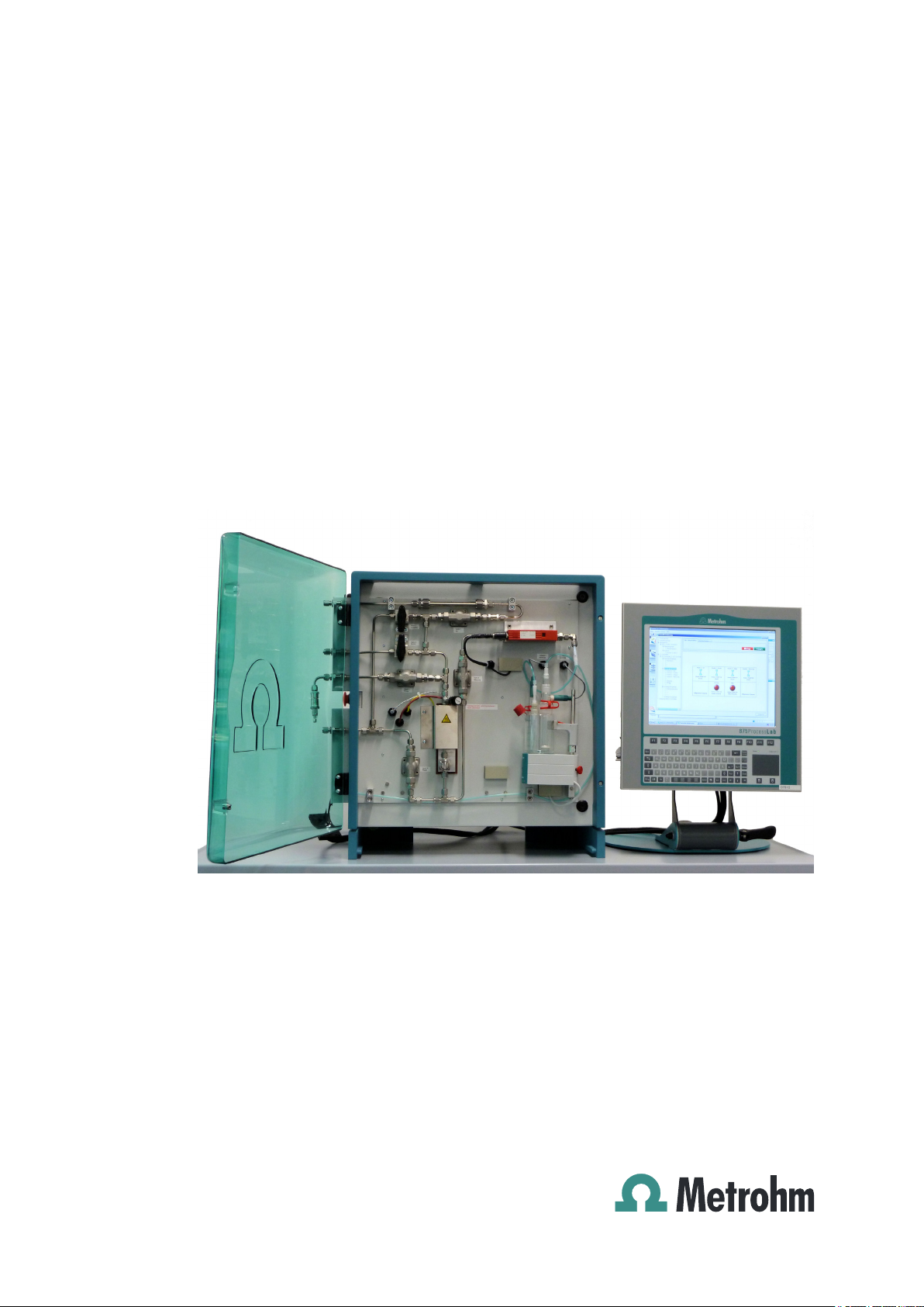
Figure 1 Operating unit and analysis module ................................................... 7
Figure 2 Schematic arrangement of the system ............................................... 7
Figure 3 I/O controller ................................................................................... 12
Figure 4 Schematic arrangement of the system ............................................. 16
Figure 5 Sample vessel connector ................................................................. 17
Figure 6 Schematic representation of the gas flows during an analysis .......... 20
Figure 7 Formula for calculating the extraction time ...................................... 22
Figure 8 Typical shape of the gas flow curve and drift curve .......................... 23
Figure 9 Systematic procedure for identifying the cause of drift rises ............. 37
Table of figures
■■■■■■■■
V
Page 8

Page 9

■■■■■■■■■■■■■■■■■■■■■■
1 Introduction
1.1 Instrument description
The 875 KF Gas Analyzer is a robust, modularly designed analysis system
based on tiamo™ for routine analysis at a site.
The system described on the following pages has been devised for the
coulometric water content determination according to Karl Fischer in
gases and allows the analysis of both liquefied gases and permanent
gases. This method is also suitable for very low water contents.
The system comprises an operating unit and an analysis module. The analysis module is equipped with a base plate to convey the gas and with a
water content determination cell as well as internally with an 851 Titrando
in order to carry out all required analysis steps fully automatically. For this
process, an amount of gas defined by the user is precisely measured with
the flow meter and fed to the connected coulometer cell. Sample residue
and water that might be present in the piping system are rinsed with dry
nitrogen. The water is absorbed by the coulometric reagent and determined there by way of Karl Fischer titration. In coulometry, the iodine
required for titration is produced by anodic oxidation, and the water content is subsequently determined. For the determination of liquefied gases,
the samples are first vaporized in a controlled manner and then conveyed
to sample determination.
1 Introduction
Please also refer to the manuals and the documentation regarding the
individual components (851 Titrando, mass flow controller, individual
components) in addition to this documentation of the KF Gas Analyzer.
1.2 System description
■ Robust analysis system with high-quality components for routine analy-
sis tailored to the requirements of users.
■ Gas-carrying system separate from the electronics and the power sup-
ply.
■ The base plate with the system components is mounted behind a
hood.
■ The base plate comprises all components of gas conveyance and prep-
aration as well as the coulometer cell.
■ The base plate's gas system is pressure-tested.
■ Nitrogen feed line with drying cartridge for predrying and check valve.
■ Sample input filter preventing particles from entering the gas system.
■ Deaeration bypass for pressure release during gas change.
■■■■■■■■
1
Page 10

1.3 System specification
■ Integrated, adjustable vaporizer for liquefied gases.
■ Heated oil filter with stainless steel filter element for analyzing used
refrigerants with chiller oil contents.
■ Rinsing connector for removing oil residue.
■ Precise gas measurement with mass flow controller (MFC).
■ Automated analysis process thanks to the use of solenoid valves.
■ Predefined analysis method with a prerinsing, gas feed and postrinsing
phase.
■ Coulometric procedure for direct water content determination.
■ Industrial PC and TFT panel (available as an option).
■ All components except for the TFT panel are contained in one housing.
■ Flexible control, user-friendly method creation and management and
extensive data management using the tiamo™ software. The operation of tiamo™ is described in the online help. Complete integration
and control of all system components via the software.
1.3 System specification
■ The system must be operated in a fume cupboard.
■ Maximum sample input pressure: 40 bar.
■ Maximum vaporization temperature: 80 °C.
■ Nitrogen is required as auxiliary gas. The molecular sieve is used for
predrying in the 875 KF Gas Analyzer. The input pressure must correspond to the vapor pressure of the samples.
■ Gas connectors for nitrogen, rinsing medium, high-pressure waste gas:
6 mm Swagelok ferrule screw connector.
■ Sample gas connector: 1/16'' or 6 mm Swagelok ferrule screw connec-
tor.
■ Gas type: The system is suitable for the liquefied gases and permanent
gases listed below. The gas system must be rinsed with nitrogen after
each measurement. Additional gases may be approved on request and
after testing.
– Propane, propene, butane, butene, butadiene, LPG, natural gas
– Dimethyl ether, ethylene oxide
– Chlorinated hydrocarbons: methyl chloride, ethyl chloride, vinyl
chloride
– Refrigerants: various chlorofluorocarbon (CFC), hydrofluorocar-
bon (HFC) and chlorinated hydrocarbon (CHC) compounds.
Fresh and used refrigerants with chiller oil contents.
■ Safety specification: degree of protection IP54.
■■■■■■■■■■■■■■■■■■■■■■
■■■■■■■■
2
Page 11
■■■■■■■■■■■■■■■■■■■■■■
NOTE
The materials of the components used have been carefully selected in
accordance with the aforementioned gases. According to the current
state of technology and the material manufacturers' resistance lists,
these materials are resistant to the aforementioned gases.
However, a general guarantee is impossible to give, as we cannot predict how the gas mixtures will behave in the system and we do not
know the concentration, degree of purity and aggregate state of the
various gases that flow through the system.
1.4 About the documentation
CAUTION
1 Introduction
Please read through this documentation carefully before putting the
instrument into operation. The documentation contains information
and warnings which the user must follow in order to ensure safe operation of the instrument.
1.4.1 Symbols and conventions
The following symbols and formatting may appear in this documentation:
Method Dialog text, parameter in the software
File ▶ New Menu or menu item
[Next] Button or key
Cross-reference to figure legend
The first number refers to the figure number, the second to the instrument part in the figure.
Instruction step
Carry out these steps in the sequence shown.
Warning
This symbol draws attention to a possible life hazard
or risk of injury.
■■■■■■■■
3
Page 12
1.5 Safety instructions
■■■■■■■■■■■■■■■■■■■■■■
Warning
This symbol draws attention to a possible hazard due
to electrical current.
Warning
This symbol draws attention to a possible hazard due
to heat or hot instrument parts.
Warning
This symbol draws attention to a possible biological
hazard.
Caution
This symbol draws attention to a possible damage of
instruments or instrument parts.
Note
This symbol marks additional information and tips.
1.5 Safety instructions
1.5.1 General notes on safety
WARNING
This instrument may only be operated in accordance with the specifications in this documentation.
The present system is suitable for processing gases and liquefied gases. In
addition, hazardous substances are used in the wet end. Usage therefore
requires the user to have basic knowledge and experience in handling liquefied gases, gases and pressurized media. Knowledge with respect to the
application of the fire prevention measures prescribed for laboratories is
also mandatory. The system may be operated only by trained staff. The
operator must be trained both with regard to these operating instructions
and the customer's laboratory rules and regulations.
This instrument has left the factory in a flawless state in terms of technical
safety. To maintain this state and ensure non-hazardous operation of the
instrument, the following instructions must be observed carefully.
■■■■■■■■
4
Page 13
■■■■■■■■■■■■■■■■■■■■■■
1 Introduction
NOTE
Check all connections of the system for leakage at regular intervals and
particularly after having made any modifications.
WARNING
The gas system is under pressure. It contains both pressurized gases
and liquefied gases.
Before the sample vessel can be changed, the pressure must be
released in the piping system and the latter may need to be rinsed with
nitrogen.
Observe the applicable regulations.
WARNING
The oven used for vaporizing the liquefied gases and the oil filter downstream of the oven may exhibit a temperature of up to 70 °C. Avoid
direct skin contact. Wear heat-insulating gloves, if necessary.
Clean the oil filter and rinse the piping carrying gas through the oven
only with the instrument switched off and while it is cold.
1.5.2 Electrical safety
The electrical safety when working with the instrument is ensured as part
of the international standard IEC 61010.
Only personnel qualified by Metrohm are authorized to carry out service
work on electronic components.
Never open the housing of the instrument. The instrument could be
damaged by this. There is also a risk of serious injury if live components
are touched.
WARNING
WARNING
There are no parts inside the housing which can be serviced or replaced
by the user.
■■■■■■■■
5
Page 14
1.5 Safety instructions
■■■■■■■■■■■■■■■■■■■■■■
Mains voltage
WARNING
An incorrect mains voltage can damage the instrument.
Only operate this instrument with a mains voltage specified for it (see
rear panel of the instrument).
Protection against electrostatic charges
WARNING
Electronic components are sensitive to electrostatic charges and can be
destroyed by discharges.
Do not fail to pull the mains cable out of the mains connection socket
before you set up or disconnect electrical plug connections at the rear
of the instrument.
1.5.3 Flammable solvents and chemicals
WARNING
All relevant safety measures are to be observed when working with
flammable solvents and chemicals.
■ The instrument must be set up in a fume cupboard.
■ Keep all sources of flame far from the workplace.
■ Clean up spilled liquids and solids immediately.
■ Follow the safety instructions of the chemical manufacturer.
1.5.4 Recycling and disposal
This product is covered by European Directive 2002/96/EC, WEEE – Waste
from Electrical and Electronic Equipment.
The correct disposal of your old equipment will help to prevent negative
effects on the environment and public health.
More details about the disposal of your old equipment can be obtained
from your local authorities, from waste disposal companies or from your
local dealer.
■■■■■■■■
6
Page 15
■■■■■■■■■■■■■■■■■■■■■■
2 Overview of the instrument
2.1 Instruments
Figure 1 Operating unit and analysis module
2 Overview of the instrument
2.2 Piping diagram
A
Nitrogen
Figure 2
Schematic arrangement of the system
Rinsing with solvent
B
■■■■■■■■
7
Page 16

2.3 I/O controller
■■■■■■■■■■■■■■■■■■■■■■
Sample
C
To the coulometer cell
E
Drying cartridge (nitrogen)
1
Valve 1 (nitrogen)
3
Mass flow controller
5
Valve 2 (sample)
7
Sample input filter
9
Vaporizer
11
Oil filter, heated
13
2.3 I/O controller
Digital inputs
Table 1
Digital inputs
Waste gas
D
Stopcock 1 (deaeration)
2
Check valve
4
Stopcock 2 (rinsing with solvent)
6
Valve 4 (measurement)
8
Precision control valve (vaporizer regu-
10
lator)
Valve 3 (waste gas)
12
Terminal Function Port Port description
KL1104-1-1 E1 DigIn_1_1_1 QUICKSTOP
KL1104-1-2 +24 V
KL1104-1-3 GND
KL1104-1-4 E3 DigIn_1_1_3
KL1104-1-5 E2 DigIn_1_1_2
KL1104-1-6 +24 V
KL1104-1-7 GND
KL1104-1-8 E4 DigIn_1_1_4
Digital outputs and relay outputs
Table 2
Digital outputs and relay outputs
Terminal Function Port Port description
KL2424-2-1 A1 DigOut_1_2_1 Valve1 - N2
KL2424-2-2 GND
KL2424-2-3 GND
KL2424-2-4 A3 DigOut_1_2_3 Valve 3 - waste gas
■■■■■■■■
8
Page 17

■■■■■■■■■■■■■■■■■■■■■■
2 Overview of the instrument
Terminal Function Port Port description
KL2424-2-5 A2 DigOut_1_2_2 Valve 2 - sample
KL2424-2-6 GND
KL2424-2-7 GND
KL2424-2-8 A4 DigOut_1_2_4 Valve 4 - measure-
ment
Protective ground
conductor terminal, 4-
Earth Terminals 1 - 4 Earth for each of the
4 valves
pin
KL2424-3-1 A1 DigOut_1_3_1 -
KL2424-3-2 GND
KL2424-3-3 GND
KL2424-3-4 A3 DigOut_1_3_3 MFC
KL2424-3-5 A2 DigOut_1_3_2 Heater
KL2424-3-6 GND
KL2424-3-7 GND
KL2424-3-8 A4 DigOut_1_3_4 -
Analog inputs
Table 3
Analog inputs
Terminal Function Port Port description
KL3204-4-1 +I1 AnIn_1_4_1 Oven temperature
KL2424-4-2
KL2424-4-3 +I3 AnIn_1_4_3 -
KL2424-4-4 GND
KL2424-4-5 +I2 AnIn_1_4_2 -
KL2424-4-6 GND
KL2424-4-7 +I4 AnIn_1_4_4 -
KL2424-1-8 GND
■■■■■■■■
9
Page 18

3.1 Setting up the instrument
3 Installation
3.1 Setting up the instrument
3.1.1 Packaging
The instrument is supplied in highly protective special packaging together
with the separately packed accessories. Keep this packaging, as only this
ensures safe transportation of the instrument.
3.1.2 Checks
Immediately after receipt, check whether the shipment has arrived complete and without damage by comparing it with the delivery note.
3.1.3 Location
The instrument has been developed for operation indoors and may not be
used in explosive environments.
■■■■■■■■■■■■■■■■■■■■■■
Place the instrument in a location of the laboratory which is suitable for
operation and free of vibrations and which provides protection against
corrosive atmosphere and contamination by chemicals to the greatest
extent possible.
The instrument should be protected against excessive temperature fluctuations and direct sunlight.
The 875 KF Gas Analyzer must be set up at a location of the laboratory
equipped with a fume cupboard.
The operating unit is set up next to the analysis module.
■■■■■■■■
10
Page 19

■■■■■■■■■■■■■■■■■■■■■■
3.2 General
The 875 KF Gas Analyzer is delivered in a largely preconfigured state.
As a rule, the installation steps described in the individual manuals have
been carried out prior to delivery.
Additional notes are described in the subchapters below.
Fill the nitrogen drying cartridge with molecular sieve.
Establish the gas connections for nitrogen and, if required, for rinsing
medium with 6 mm Swagelok ferrule screw connectors.
Establish the gas connection for the sample with 1/16'' Swagelok ferrule
screw connector.
Connect the high-pressure waste gas and the waste gas of the coulometer cell to the extraction system.
3.3 Power connection
3 Installation
WARNING
The on-site supply voltage has to match the voltage specified on the
875 KF Gas Analyzer's housing.
The instrument is set to either 110 V or 230 V at the power supply unit.
The 875 KF Gas Analyzer and the operating unit are both connected to a
socket with the preinstalled power feeder.
WARNING
Electrical connections may only be made by authorized specialist personnel.
■■■■■■■■
11
Page 20

3.4 Connecting control lines
1 2 3
3.4 Connecting control lines
WARNING
Always disconnect the instrument from the supply voltage.
Only shielded cables may be used for digital outputs, digital inputs, analog
outputs and analog inputs.
The cable shielding must be connected to the grounding terminal.
The lines are connected directly to the I/O controller (see Chapter 2.3,
page 8).
In order to open the contact springs, insert a 2.5 x 0.4 mm screw driver
vertically into the rectangular actuation opening and press towards the
LED.
A prefabricated cable has to be connected to the computer's network
card directly if the 875 KF Gas Analyzer is being integrated into a LAN.
■■■■■■■■■■■■■■■■■■■■■■
■■■■■■■■
12
Analog output terminals
1
Digital input terminals
3
Figure 3
I/O controller
Digital output terminals
2
Page 21

■■■■■■■■■■■■■■■■■■■■■■
3.5 Connecting the PC and the operating unit
The operating unit is connected directly to the industrial PC at the labeled
locations.
The cable entry plate is screwed onto the 875 KF Gas Analyzer's housing.
3.6 Windows passwords
User Password Group
Gas Analyzer User
Administrator ADMINISTRATOR Administrator
Metrohm ******* Administrator
3.7 Gas connections
3 Installation
WARNING
Lines must be laid in such a way that they cannot be pulled out.
Nitrogen, sample, high-pressure waste gas
The connection between sample vessel and the Gas Analyzer's sample
input must be as short as possible, have as little dead volume as possible,
be absolutely tight and consist of suitable material. Observe the notes in
the enclosed assembly instructions from Swagelok on connecting the
Swagelok ferrule screw connectors.
Waste gas lines
The waste gas lines must be routed to the exhaust air system with no
counterpressure.
■■■■■■■■
13
Page 22

3.8 Drying cartridge for nitrogen
3.8 Drying cartridge for nitrogen
Depending on the residual water content of the nitrogen, the cartridge is
to be filled with dried molecular sieve.
Secure the filling in place with a glass wool plug on both sides. In addition, insert a sieve disk (enclosed in the delivery as an accessory) on the
output side (right).
3.9 851 Titrando
NOTE
For installation and preparation, refer to the manual of the 851
Titrando.
Both electrodes (indicator electrode and generator electrode) are protected from being pushed out with an SGJ clip.
■■■■■■■■■■■■■■■■■■■■■■
Given the gas flow, only the adsorber tube with enlarged bore supplied is
to be used (see Chapter 9.5, page 45).
The adsorber tube and the stopper of the gas infeed tip are not secured in
order to prevent an uncontrolled pressure rise.
3.10 Shutting down
If the system is shut down for an extended period of time, then the entire
gas system (gas flow to the coulometer, waste gas, rinsing and bypass
piping) has to be rinsed with nitrogen ("Shut down system" method) and
the coulometer cell has to be cleared of reagent and rinsed with dry methanol or ethanol. The cell can then be stored in a dry place.
■■■■■■■■
14
Page 23

■■■■■■■■■■■■■■■■■■■■■■
4 Operation
4.1 Arrangement of the gas-carrying system
The valve arrangement mounted on the front plate of the 875 KF Gas
Analyzer permits a safe and complete transfer of the sample and the
water contained in it into the coulometric titration cell. The diagram (see
Figure 4, page 16) shows the schematic arrangement of the gas-carrying system.
The sample is introduced into the apparatus via valve 2 (4-7) and vaporized at the precision control valve (regulator). The heating block (4-11)
compensates the heat that is lost in the system due to the enthalpy of
vaporization and thus prevents the water to be analyzed from condensing
or cooling.
The gas-carrying components are automatically rinsed with nitrogen that
is predried in a drying cartridge (4-1) via valve 1 (4-3) before and after the
sample is introduced. This nitrogen rinsing completely removes sample gas
from the piping, so that no errors resulting from dead volumes can occur.
Furthermore, rinsing with inert gas ensures that the water load on seals
and internal metal surfaces in the apparatus is equal before and after sample introduction. Memory effects can be ruled out in this way.
4 Operation
The sample amount is metered with a mass flow controller (4-5), which
records the amount of gas flowing in and regulates the volumetric flow.
During the introduction of liquefied gases, no pressure may build up
downstream of the precision control valve, as this would entail the risk of
sample condensing upstream of and within the mass flow controller and
possibly interfere with the flow control and damage the instrument. For
this reason, the precision control valve should be adjusted in such a way
that the setpoint value for the mass flow controller is not achieved. As an
additional safety, the system is equipped with a control that closes the
sample input valve if the gas flow exceeds a threshold value defined as
common variable.
When a new sample is connected, the feed line is first prerinsed with sample via valve 3 (4-12). This is necessary because, initially, the connection
fittings of gas bottles generally release water into the passing sample and
the results of the first measurement without sample rinsing are generally
higher. At the end of the measurement, the user can release the pressure
from the sample infeed via stopcock 1 (4-2) in a controlled manner. The
infeed line is then no longer under pressure when the gas container is disconnected.
■■■■■■■■
15
Page 24

4.1 Arrangement of the gas-carrying system
If samples contain nonvolatile parts, such as oil contaminations, then
these parts are held back by the filter element (4-13). Contamination of
the mass flow controller is thus excluded.
A thermally conductive connection exists between the oil filter and the
heating block, which significantly increases the filter temperature. The
retarding effect of oils on water is reduced in this way. The filters and the
vaporizer are cleaned by rinsing the lines with a suitable solvent via stopcock 2 (4-6). The corresponding dosing device forms part of the optional
scope of delivery of the 875 KF Gas Analyzer.
■■■■■■■■■■■■■■■■■■■■■■
■■■■■■■■
16
Nitrogen
A
Sample
C
To the coulometer cell
E
Drying cartridge (nitrogen)
1
Valve 1 (nitrogen)
3
Mass flow controller
5
Valve 2 (sample)
7
Sample input filter
9
Figure 4 Schematic arrangement of the system
Rinsing with solvent
B
Waste gas
D
Stopcock 1 (deaeration)
2
Check valve
4
Stopcock 2 (rinsing with solvent)
6
Valve 4 (measurement)
8
Precision control valve (vaporizer regu-
10
lator)
Page 25
■■■■■■■■■■■■■■■■■■■■■■
4 Operation
Vaporizer
11
Oil filter, heated
13
Figure 5 Sample vessel connector
Liquid phase
A
Stopcock
1
4.2 Methods
Valve 3 (waste gas)
12
Gas phase
B
Sample input to 875 KF Gas Analyzer
2
WARNING
The gas system is under pressure. It contains both pressurized gas and
liquefied gas.
The prescribed analysis procedure may not be modified. Users must
have detailed knowledge of the gas conveyance in order to use the
manual operation. Uncontrolled operation of the valves may result in a
sudden vaporization of the liquefied gas or in pressure surges.
NOTE
The correct position of the precision control valve has a decisive effect
on the precision of the analysis. The exact position has to be determined for each gas type.
As standard, the 875 KF Gas Analyzer is delivered with the following
methods (control programs of the tiamo™ software):
■ Sample measurement
■ Reference measurement
■ Precision control valve setting
■ Gas calibration_liquefied gas
■■■■■■■■
17
Page 26

4.2 Methods
■ Gas calibration_gas
■ Shut down system
■ Drift diagnosis
■ System preparation
■■■■■■■■■■■■■■■■■■■■■■
The following methods form part of the optional scope of delivery:
■ Rinsing with solvent
■ Reagent replacement
■ Addition of methanol
NOTE
Please note:
The tiamo™ method can only be run if the Flow program has been
started.
4.2.1 Sequence of the "Sample measurement" method
The water content determination of the samples is controlled by the Sample measurement method, which basically consists of three steps:
■ Prerinsing the line route with nitrogen
■ Feeding in the sample
■ Postrinsing with nitrogen
The method is designed in such a way that the pressure prevailing in the
area before the regulator (line volume between precision control, nitrogen
and sample valve) is released during the change from prerinsing to sample
introduction and from sample introduction to postrinsing. In this way, a
mixing of nitrogen and sample that could result in faulty measurements is
prevented. The entire sequence is shown in (see Table 4, page 18).
The flow diagrams of the analysis are visualized in figure 6. Some partial
steps are only run through if the corresponding scans are set to "yes" in
the sample table. The dosing device for methanol addition and reagent
replacement as well as for the automated rinsing with solvent is an
optional equipment of the 875 KF Gas Analyzer.
Table 4
Gas conveyance and valve control during the analysis
Partial step Condition Opened valves Stop condition
Prerinsing with sample
Method variable "first
sample measure-
Sample valve
Waste gas valve
90 seconds expired
ment?" is set to "yes"
■■■■■■■■
18
Page 27

■■■■■■■■■■■■■■■■■■■■■■
Partial step Condition Opened valves Stop condition
4 Operation
Draining of the sample that flowed into
the area upstream of
Method variable "first
sample measurement?" is set to "yes"
Waste gas valve 60 seconds expired
the regulator
Rinsing out the waste
gas line with nitrogen
Method variable "first
sample measure-
Nitrogen valve
Waste gas valve
ment?" is set to "yes"
Prerinsing with nitrogen
Pressure release nitro-
None Nitrogen valve
Measurement valve
None Measurement valve 20 seconds expired
gen
Sample introduction None Sample input valve
Measurement valve
Pressure release sam-
None Measurement valve Gas flow falls below
ple
45 seconds expired
Status message from
the coulometer "Conditioning OK", but at
least 60 seconds
Value entered for
minimum sample
amount (mg) in the
method variable is
achieved
30 mL/min for more
than 6 seconds
Postrinsing with nitrogen
Relieving the sample
infeed
None Nitrogen valve
Measurement valve
Method variable "disconnect gas container
Sample valve
Stopcock 1
after measurement?"
is set to "yes"
Stop criteria of the
coulometric KF titration are met (extraction time and relative
drift)
■■■■■■■■
19
Page 28
4.2 Methods
■■■■■■■■■■■■■■■■■■■■■■
Figure 6 Schematic representation of the gas flows during an analysis
Red marking = sample flow Green marking = nitrogen
Prerinsing with sample
1
Prerinsing and postrinsing with nitro-
3
gen
Relieving the sample infeed
5
Rinsing out the waste gas line with
2
nitrogen
Sample introduction
4
Rinsing the feed line with nitrogen
6
4.2.2 Working steps for carrying out a measurement
Load the sample table Standard sample table gas measurement in
the run window of your tiamo™ workplace under Determination
series ▶ Sample table ▶ Load. This sample table is preset in such a way
that you can make the entries that are relevant for you. The input window
opens by double-clicking in the first line of the table template.
■■■■■■■■
20
Page 29

■■■■■■■■■■■■■■■■■■■■■■
4 Operation
Gas type
Designation of a sample (substance or substance mixture), such as butadiene or propane, selected from the drop-down bar. The gas type is linked
to the calibration factor that is stored under the same name as common
variable.
Sample number
Sample ID used to identify your sample. The designation may be changed.
It is also possible to assign further sample identifications. These must be
created in the method and in the sample table.
Minimum sample amount
Valve 2 closes after the amount of sample entered in this field has been
fed in.
Sample infeed is only completed after the sample contained in the area
upstream of the regulator has flowed out.
Recommended range: approx. 1,000 to 2,500 mg, depending on the
water content.
First sample measurement?
(yes/no)
Enter yes here in the case of the first measurement after a gas bottle has
been connected. In this case, the feed line is rinsed with sample first.
Disconnect gas container after measurement?
(yes/no)
Enter yes here if you would like to disconnect the gas bottle after the
measurement. The pressure is then released from the feed line via valve 1
in a controlled manner after the analysis and the feed line is subsequently
rinsed with nitrogen.
■■■■■■■■
21
Page 30

4.2 Methods
■■■■■■■■■■■■■■■■■■■■■■
4.2.3 Explanations regarding the shape of the gas flow and titration curves
The analysis procedure described in (see Chapter 4.2.1, page 18) results in
a characteristic shape of the gas flow and titration curves. The sample
infeed phase concludes with the gas flow dropping to a value close to
zero. The titration rate (drift) follows this drop with a delay of
approx. 10 seconds. If the gas flow is below a threshold value defined as
common variable for 6 seconds, then the nitrogen valve opens and postrinsing commences.
The amount of water detected in the postrinsing phase increases if the
samples contain nonvolatile components that remain in the vaporizer and
the oil filter. The distribution of the liquid and the gas phase balances out
during the infeed phase, so that, at the end of the infeed phase, a part of
the water contained in the sample is still present in the instrument's piping. Postrinsing serves to remove the retained water. Hydrophilic, nonvolatile sample components, such as glycol ester oils used in the refrigerant
industry, for instance, therefore lead to a flattening of the drift curve during the infeed phase and as a result to an extension of the analysis time.
As a general rule, the minimum titration time (extraction time) has to
extend beyond the beginning of the postrinsing phase, as the titration
would otherwise be finished in the "trough" between infeed and postrinsing. The control program uses the following formula to calculate the
extraction time:
Figure 7
Extraction time
te
value in mg/min saved under CV.mean
v
mass flow
The default value of the time for postrinsing common variable is
3 minutes. If a sample requires a longer postrinsing phase, then the value
must be increased accordingly.
Formula for calculating the extraction time
Minimum sample amount in mg
m
Value in sec entered under CV.time for
tn
postrinsing
■■■■■■■■
22
Page 31

■■■■■■■■■■■■■■■■■■■■■■
0
200
400
600
800
1,000
1,200
0.0 0.5 1.0 1.5 2.0 2.5 3.0 3.5 4.0
0
5
10
15
20
25
30
35
40
Gas flow [mL/min]
Time (min)
Drift [mL/min]
Start of post-rinsing
with nitrogen
Drift [mL/min]
Gas flow [mg/min - mL/min]
4 Operation
Figure 8 Typical shape of the gas flow curve and drift curve
Gas type
Propene
Minimum sample amount
0.5 g
4.2.4 Method "Reference measurement"
The trueness of the analysis can be checked by measuring water-spiked
reference gases using the Reference measurement method.
Control gases with certified water contents are commercially available.
The Reference measurement method relies on the nitrogen calibration
of the mass flow controller integrated in the instrument; i.e., it only delivers correct values if nitrogen is used as reference gas. The procedure for
reference measurement is the same as the one applied for sample mea-
surement. The result is indicated as a recovery rate in percent.
4.2.5 Changing the gas type
If the measurement of a new sample coincides with a change of the gas
type, then the flow rate of the precision control valve has to be adjusted
to the current sample using the Precision control valve setting
method. This method sets the setpoint value at the MFC to the maximum
value of 5 L/min and graphically displays the current flow by utilizing the
internal nitrogen calibration. In order to prevent a pressure rise in the area
after the regulator, the precision control valve has to be set in such a way
that its vaporization rate is lower than 5 L/min and the setpoint value is
not reached at the MFC. After the start of the method, follow the instructions of the text messages and adjust the precision control valve so that
the gas flow is within the required limits (definition by common variable).
Sample amount
1.25 g
Vaporization temperature
70 °C
■■■■■■■■
23
Page 32

4.2 Methods
NOTE
Please note:
This method does not use the calibration factor that is assigned to this
gas type. The mass flow displayed during the subsequent analysis may
therefore considerably deviate from the value that was set when the
precision control valve was adjusted.
4.2.6 Calibrating a new gas type
At the factory, the mass flow controller is calibrated to nitrogen. If the
instrument is to be operated with a different gas, then the flow value has
to be corrected by an appropriate factor. These correction factors are
determined gravimetrically by letting larger amounts of gas flow through
the MFC and monitoring the weight reduction of the gas container. The
quotient of the gas volume indicated and the weight difference is the correction factor. This factor is in the range between 0.5 and 1.5 mL for most
liquefied gases. The correction factors have to be individually determined
for each flow controller using the Gas calibration method. This method
saves the correction factor in the tiamo™ configuration as common variable. In order to achieve a sufficient level of accuracy, the sample weight
difference should have at least three significant places. The balance used
therefore has to offer a corresponding resolution and maximum weight in
accordance with the gas bottle size. For the determination of the calibration factor, the gas container has to be connected to the 875 KF Gas Analyzer with the flexible plastic capillary (OD 1/16'') enclosed in the scope of
delivery, as steel capillaries transmit vibrations to the balance.
■■■■■■■■■■■■■■■■■■■■■■
■■■■■■■■
24
Samples should be taken from the gas phase Gas calibration_gas rather
than the liquid phase of the gas container Gas calibration_liquefied
gas for calibrations, because the flow pattern is much more uniform if
vaporization does not take place in the 875 KF Gas Analyzer. The Gas cal-
ibration_liquefied gas method is only to be used if a water content
determination is to be done for the same gas container after calibration.
The procedure to determine the calibration factor is described below step
by step using butadiene as an example:
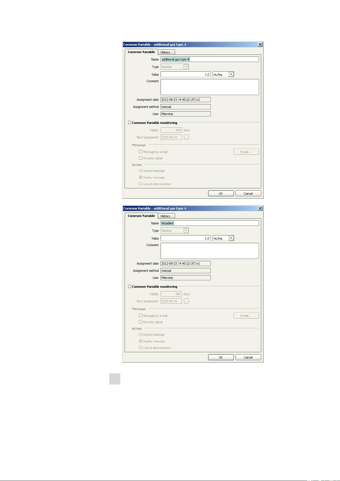
You can find the correction factors for the gases you have used so
1
far in the Common Variable subwindow in the tiamo™ configuration. Templates with the designation "additional gas type x" (x = 1 to
9) are stored for adding further gases. The common variables can be
rendered editable via Edit ▶ Properties. Replace the blank variable
additional gas type x with the lowest number x by the term butadiene.
Page 33
■■■■■■■■■■■■■■■■■■■■■■
4 Operation
Enter the name of your gas type also in the additional gas type x
2
text template under Tools ▶ Text templates ▶ Text templates
for ID in the workplace of tiamo™.
■■■■■■■■
25
Page 34

4.2 Methods
■■■■■■■■■■■■■■■■■■■■■■
Open the Gas calibration_liquefied gas method under
3
File ▶ Open in the Methods part of tiamoTM. The method consists
of tracks that run from the top to the bottom. Each track is labeled
with a letter. The individual commands are numbered consecutively
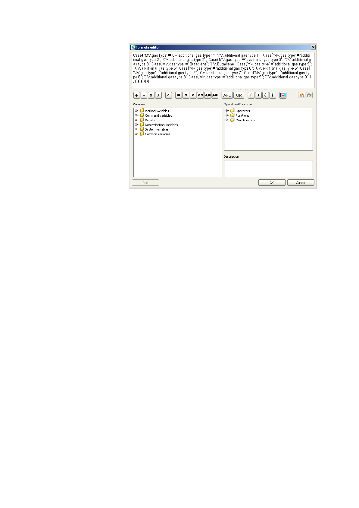
from the top to the bottom. Search the R4 call command in the exit
track. Double-click on the command to edit it. Overwrite the first line
saying additional gas type by editing the line via the properties.
Click on the ÷ symbol to open the formula editor. Replace the term
additional gas type x in inverted commas with butadiene.
■■■■■■■■
26
Page 35

■■■■■■■■■■■■■■■■■■■■■■
4 Operation
Edit the CALC command of the track to which the previously modi-
4
fied call command refers (in the example above, the track name was
K additional gas type 4). Double-clicking in the calculation line opens
a subwindow for the result properties. Click on the Options tab,
select butadiene as common variable and then save the method with
File ▶ Save.
■■■■■■■■
27
Page 36

4.2 Methods
■■■■■■■■■■■■■■■■■■■■■■
■■■■■■■■
28
Page 37

■■■■■■■■■■■■■■■■■■■■■■
Now load the Gas calibration_liquefied gas method in the sam-
5
ple table of your tiamo™ workplace. Select the designation of the
gas type that was newly added and enter a target value for the sample gas volume (recommended range: approx. 20 L). This is the value
that is displayed with the internal nitrogen calibration and not the
actual gas volume of your sample. This value should be approx. 1.5
times the gas amount (in grams) which you want to convey through
the instrument.
4 Operation
Tare the balance and start the method. After the target value has
6
been reached, a prompt appears in which you have to enter the
weight difference after gas infeed. The prefix does not matter for
this.
■■■■■■■■
29
Page 38

4.2 Methods
■■■■■■■■■■■■■■■■■■■■■■
Check whether a valid value is entered under the corresponding
7
common variable in the configuration.
Load the Sample measurement method in the tiamo™ Methods
8
part with File ▶ Open and double-click on the A6 calculation command to open it.
Edit the line A7 checking gas volume via the properties and open
9
the formula editor by clicking on the ÷ symbol. An if-then query (nested CASE function) then opens; in this query the additional gas type x
that you have replaced with butadiene is listed twice in a row.
Replace the term additional gas type x with butadiene also here and
save the method using File ▶ Save. You can now select your new
gas type for the subsequent analyses, and the method automatically
uses the appropriate correction factor for the calculations.
■■■■■■■■
30
Page 39
■■■■■■■■■■■■■■■■■■■■■■
4 Operation
4.2.7 Automatic addition of methanol, automatic reagent replacement (optional accessories)
The anolyte in the coulometer cell consists mainly of methanol, which is
removed to a considerable extent by the sample gas and the rinsing gas.
The fill level of the measuring solution therefore decreases by approx.
8 mL per hour under normal operating conditions. In order to avoid malfunctions and faulty measurements, the missing methanol must be added
regularly. This can be done manually with a syringe. Alternatively, the KF
Gas Analyzer can be equipped with a dosing device to add methanol cyclically that is part of the optional scope of delivery. The rate at which the fill
level decreases depends on the composition and temperature of the anolyte. The fill level can be increased if necessary using the
Addition of methanol method. The Reagent replacement method is
used for a complete exchange of anolyte.
4.2.8 Rinsing with solvent (optional accessories)
If liquefied gases contain nonvolatile components, these components precipitate in the piping of the KF Gas Analyzer. This is particularly the case
for used refrigerants, which are usually contaminated with compressor
oils. To prevent the sensitivity of the mass flow controller's sensors being
compromised by such substances, an oil filter made of sintered stainless
steel is located beneath the vaporizer. However, an infeed of larger
amounts of oil results in a measurable retardation of the water in the piping and additionally increases the flow resistance of the oil filter, as its
pores are covered by the oil. If samples contaminated with oil are to be
measured, the system has to be rinsed with a suitable solvent from time to
time.
■■■■■■■■
31
Page 40

4.3 QUICKSTOP module
The rinsing medium has to fulfill the following requirements:
■ It has to be a suitable solvent for the nonvolatile residues.
■ It has to exhibit a low boiling point, as it can be removed from the pip-
ing only by nitrogen rinsing.
Petroleum ether with a boiling range between 40 °C and 60 °C is recommended for oil contaminations. The rinsing medium is dosed with a dosing device that is optionally available. The system can be cleaned with the
Rinsing with solvent method. The precision control valve must be
entirely open during rinsing. For the subsequent sample measurements,
the precision control valve has to be adjusted to the corresponding sample
again using the Precision control valve setting method.
4.3 QUICKSTOP module
The red button on the left side of the housing resets all modules that are
connected to the I/O controller to their default state (this usually means
switched off), e.g., heater, valves and potential-free signal contacts.
■■■■■■■■■■■■■■■■■■■■■■
The button locks in place and has to be pushed again to unlock.
Dosinos, stirrers and other devices that are connected directly to the 851
Titrando are not affected. They must be stopped directly in the software.
If an automatic analysis is running, then the quickstop module input can
be queried in this tiamo™ method. Thus, the devices connected to the
851 Titrando can also be stopped in this method.
■■■■■■■■
32
Page 41

■■■■■■■■■■■■■■■■■■■■■■
5 Operation and maintenance
5.1 General notes
5.1.1 Care
WARNING
Appropriate personal safety measures must be taken for any work during which hazardous substances may be released (e.g., removing connection piping, disassembling or modifying the gas-carrying system).
Examples of these safety measures include wearing personal protective
equipment in accordance with the laboratory regulations: protective
glasses, gloves and clothing.
Rinse with nitrogen and release the pressure from the system prior to
carrying out work on the gas system.
5 Operation and maintenance
The 875 KF Gas Analyzer requires appropriate care. Excess contamination
of the instrument may result in functional disruptions and a reduction in
the lifetime of the otherwise sturdy mechanics and electronics.
Spilled chemicals and solvents should be removed immediately. Above all,
the plug connectors on the rear of the instrument (in particular the power
socket) should be protected from contamination.
CAUTION
Although this is largely prevented by design measures, the power plug
should be unplugged immediately if aggressive media have penetrated
the inside of the instrument, so as to avoid serious damage to the
instrument electronics. In such cases, Metrohm Service must be
informed.
The molecular sieve of the predrying cartridge must be exchanged at regular intervals (in accordance with the residual water content of the nitrogen used).
Please refer to the 851 Titrando manual for information on maintenance
and care of the coulometer cell.
A careful visual inspection of the gas-carrying system and the wet end has
to be performed before an analysis series is started (e.g., status of the
coulometer cell, gas connections and exhaust lines, leak-tightness). Check
all connections of the system for leakage at regular intervals and particu-
■■■■■■■■
33
Page 42

5.2 Quality Management and validation with Metrohm
larly after having made any modifications. If leakage is detected, this has
to be eliminated immediately so as to prevent instrument damages.
If the necessity to clean the oil filter should arise periodically as a result of
analyzing liquefied gases with nonvolatile components, the rinsing with
solvent (see Chapter 4.2.8, page 31) option is particularly recommended.
Given the automated rinsing, no mechanical work is required on the gascarrying system. The risk of leakage is thus eliminated. If the filter is
cleaned manually, the system's tightness should be checked again after
the filter is built in, like after any changes to the gas system.
NOTE
The nitrogen inlet's check valve, which is a safety feature in case of an
operating error, must be subjected to a functional check at least once a
year. It has to be checked whether an additional check valve is required
for the nitrogen supply.
5.1.2 Maintenance by Metrohm Service
Maintenance of the 875 KF Gas Analyzer is best carried out as part of an
annual service, which is performed by specialist personnel of the Metrohm
company. If you are frequently working with caustic and corrosive chemicals, we recommend a shorter maintenance interval.
■■■■■■■■■■■■■■■■■■■■■■
Metrohm Service offers every form of technical advice for maintenance
and service of all Metrohm instruments.
5.2 Quality Management and validation with Metrohm
Quality Management
Metrohm offers you comprehensive support in implementing quality management measures for instruments and software. Further information on
this can be found in the brochure «Quality Management with
Metrohm» available from your local Metrohm agent.
Validation
Please contact your local Metrohm agent for support in validating instruments and software. Here you can also obtain validation documentation
to provide help for carrying out the Installation Qualification (IQ) and
the Operational Qualification (OQ). IQ and OQ are also offered as a
service by the Metrohm agents. In addition, various application bulletins
are also available on the subject, which also contain Standard Operat-
ing Procedures (SOP) for testing analytical measuring instruments for
reproducibility and correctness.
■■■■■■■■
34
Page 43

■■■■■■■■■■■■■■■■■■■■■■
5 Operation and maintenance
Maintenance
Electronic and mechanical functional groups in Metrohm instruments can
and should be checked as part of regular maintenance by specialist personnel from Metrohm. Please ask your local Metrohm agent regarding the
precise terms and conditions involved in concluding a corresponding
maintenance agreement.
NOTE
You can find information on the subjects of quality management, validation and maintenance as well as an overview of the documents currently available at www.metrohm.com/com/ under Support.
■■■■■■■■
35
Page 44

6 Troubleshooting
A low and constant drift is a prerequisite for correct and precise water
content determination in the trace range. In the case of a carrier gasflooded coulometric titration cell, this drift consists of the measuring cell's
own basic drift (cell drift) and the water contained in the carrier gas.
Therefore, to the extent possible, the nitrogen used for prerinsing and
postrinsing must be water-free. Molecular sieve is capable of reducing the
residual water content to approx. 1 to 2 µg/L, which is sufficient for the
operation of the 875 KF Gas Analyzer. If the water concentration of the
inert gas used for rinsing is higher, then the gas has to be dried with
molecular sieve. A molecular sieve cartridge is located on the front plate
of the Gas Analyzer before valve 1. With 15 mL, however, its capacity is
rather limited, and therefore the cartridge only serves as a safety measure.
In an equilibrated state, the cell drift lies in a range between 1 and
3 µg/min. If a volumetric stream of 1 L/min of nitrogen that has been
dried through the molecular sieve is set for the titration cell, the cell drift
increases to approx. 2 to 4 µg/min.
■■■■■■■■■■■■■■■■■■■■■■
A drift rise is attributable either to an increase in cell drift or an increased
water infeed via the carrier gas (see Table 5, page 36).
The carrier gas' share in the total drift can be determined with the Drift
diagnosis method. This share should not exceed 2 µg/min.
Table 5
Cause Remedy
Cell drift rise due to the infeed of
reactive matrix components
Cell drift rise due to the accumulation of water and H2S in the catholyte
Water concentration rise in the
rinsing gas due to exhaustion of
the molecular sieve
Retardation of the water due to
accumulation in the vaporizer and
the oil filter
Possible causes for a drift rise
Exchange the anolyte
Exchange the catholyte
Check the nitrogen quality,
exchange the molecular sieve cartridge
Rinse the gas-carrying system with
solvent
■■■■■■■■
36
Page 45
■■■■■■■■■■■■■■■■■■■■■■
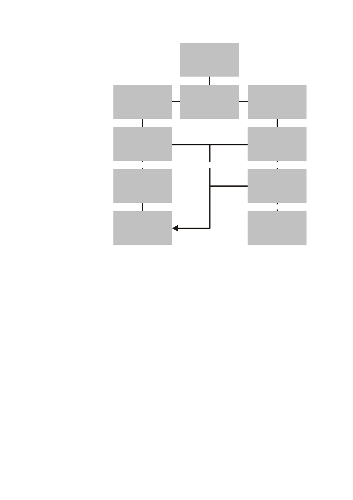
yesno no
no
Drift > 6 µg/min
Drift diagnosis
method
→
Drift rise as a result of
rinsing > 3 µg/min
Exchange
catholyte
Dryness level of
rinsing gas?
Replace molecular
sieve cartridge
Drift < 6 µg/min? Drift < 6 µg/min?
Rinse gas-
carrying system
Exchange
anolyte
Contact Metrohm
Service
End
6 Troubleshooting
Figure 9 Systematic procedure for identifying the cause of drift rises
■■■■■■■■
37
Page 46

7.1 Temperature ranges
7 Technical specifications
7.1 Temperature ranges
■■■■■■■■■■■■■■■■■■■■■■
Vaporization oven
and oil filter
maximum 80 °C
7.2 Pressure ranges
Input pressure
maximum 40 bar
7.3 Supply voltage
Nominal voltage
range
Frequency 50 or 60 Hz
Power consumption
Fuse 10 ATH (slow-acting)
110 V or 230 V, adjustable at the power supply unit
maximum 2,200 W
7.4 Safety specifications
This instrument fulfills the following electrical safety requirements:
CE marking in accordance with the EU directives:
■ 2006/95/EC (Low Voltage Directive, LVD)
■ 2004/108/EC (EMC Directive, EMC)
Design and testing According to EN/IEC/UL 61010-1, CSA-C22.2 No. 61010-1, protection
class I.
Safety instructions This document contains safety instructions which have to be followed
by the user in order to ensure safe operation of the instrument.
■■■■■■■■
38
Page 47

■■■■■■■■■■■■■■■■■■■■■■
7.5 Electromagnetic compatibility (EMC)
Emission Standards fulfilled:
■ EN/IEC 61326-1
■ EN 55022 / CISPR 22
■ EN/IEC 61000-3-2
■ EN/IEC 61000-3-3
Immunity Standards fulfilled:
■ EN/IEC 61326-1
■ EN/IEC 61000-4-2
■ EN/IEC 61000-4-3
■ EN/IEC 61000-4-4
■ EN/IEC 61000-4-5
■ EN/IEC 61000-4-6
■ EN/IEC 61000-4-11
■ EN/IEC 61000-4-14
7 Technical specifications
7.6 Dimensions
Analysis module
Width 670 mm
Height 600 mm
Depth 470 mm
Operating unit Values in brackets with pedestal.
Width 440 mm (550 mm)
Height 433 mm (433 mm)
Depth 95 mm (450 mm)
7.7 Weight
Analysis module
Operating unit 21.7 kg
56.0 kg
■■■■■■■■
39
Page 48

8.1 Quality Management Principles
8 Conformity and warranty
8.1 Quality Management Principles
Metrohm Ltd. holds the ISO 9001:2000 Certificate, registration number
10872-02, issued by SQS (Swiss Association for Quality and Management
Systems). Internal and external audits are carried out periodically to assure
that the standards defined by Metrohm’s QM Manual are maintained.
The steps involved in the design, manufacture and servicing of instruments
are fully documented and the resulting reports are archived for ten years.
The development of software for PCs and instruments is also duly documented and the documents and source codes are archived. Both remain
the possession of Metrohm. A non-disclosure agreement may be asked to
be provided by those requiring access to them.
The implementation of the ISO 9001:2000 quality management system is
described in Metrohm’s QM Manual, which comprises detailed instructions on the following fields of activity:
■■■■■■■■■■■■■■■■■■■■■■
Instrument development
The organization of the instrument design, its planning and the intermediate controls are fully documented and traceable. Laboratory testing
accompanies all phases of instrument development.
Software development
Software development occurs in terms of the software life cycle. Tests are
performed to detect programming errors and to assess the program’s
functionality in a laboratory environment.
Components
All components used in the Metrohm instruments have to satisfy the quality standards that are defined and implemented for our products. Suppliers of components are audited by Metrohm as the need arises.
Manufacture
The measures put into practice in the production of our instruments guarantee a constant quality standard. Production planning and manufacturing
procedures, maintenance of production means and testing of components, intermediate and finished products are prescribed.
Customer support and service
Customer support involves all phases of instrument acquisition and use by
the customer, i.e. consulting to define the adequate equipment for the
analytical problem at hand, delivery of the equipment, user manuals, train-
■■■■■■■■
40
Page 49

■■■■■■■■■■■■■■■■■■■■■■
ing, after-sales service and processing of customer complaints. The
Metrohm service organization is equipped to support customers in implementing standards such as GLP, GMP, ISO 900X, in performing Operational Qualification and Performance Verification of the system components or in carrying out the System Validation for the quantitative determination of a substance in a given matrix.
8.2 Warranty (Guarantee)
Metrohm guarantees that the deliveries and services it provides are free of
errors in materials, design or manufacturing.
The general warranty period is 36 months (exclusions below) from the
date of delivery or 18 months in the event of continuous operation. The
warranty remains valid on the condition that the servicing is provided by a
Service Organization authorized by Metrohm at defined intervals and with
a defined scope.
The warranty period for anion suppressors is 120 months from the date of
delivery or 60 months in the event of continuous operation.
8 Conformity and warranty
The warranty period for IC separation columns is 90 days after start-up.
For third-party components that are recognizable as such, the manufacturer's warranty regulations apply.
Consumables and materials with limited storage life and glass breakage in
the case of electrodes or other glass parts are excluded from the warranty.
Warranty claims cannot be asserted if the customer has failed to meet his
payment obligations according to schedule.
During the warranty period, Metrohm undertakes either to replace free of
charge or to credit the purchaser for any assemblies or components that
can be shown to be faulty. Any transport or customs fees that may apply
are the ordering party’s responsibility.
The precondition for this is that the ordering party must use the Return
Material Authorization (RMA) to report the faulty part, along with specification of the article number, the article designation, an adequate error
description, the delivery date and (if applicable) the serial number or the
chip data, respectively. In addition, the ordering party undertakes to store
the faulty part for at least 24 months in accordance with current storage
directives (in compliance with ESD guidelines) and to hold it in readiness
for onsite inspection or for return shipment to Metrohm. Metrohm
reserves the right to invoice the ordering party for these articles, including
retroactively, in the event of noncompliance with these pre-conditions.
The original warranty periods for the original part apply to parts that are
replaced or repaired under the above-referenced warranties (no extension
of the warranty period).
■■■■■■■■
41
Page 50

8.2 Warranty (Guarantee)
■■■■■■■■■■■■■■■■■■■■■■
Deficiencies arising from circumstances that are not the responsibility of
Metrohm, such as improper storage or improper use, etc., are expressly
excluded from the warranty.
Metrohm also offers a 120-month spare parts availability guarantee and a
60-month PC software support warranty, calculated from the date on
which the product is withdrawn from the market. The content of this warranty is the ability of the customer to obtain functioning spare parts or
appropriate software support at market prices during the time of the warranty period.
If Metrohm AG is unable to meet this obligation due to circumstances
beyond the control of Metrohm AG, then the ordering party shall be
offered alternative solutions at preferential conditions.
■■■■■■■■
42
Page 51

■■■■■■■■■■■■■■■■■■■■■■
9 Accessories
NOTE
Accessories and spare parts for the 875 KF Gas Analyzer are exclusively
available from Metrohm Germany.
NOTE
Subject to change without notice.
9.1 Scope of delivery
9 Accessories
NOTE
After receiving the instrument, check the shipment to ensure that it is
complete.
Qty.
Order no. Description
851 Titrando and coulometer cell
Please refer to the 851 Titrando manual for standard accessories.
Accessories 875 KF Gas Analyzer analysis module
Qty.
1 m 6.1803.040 PTFE capillary tubing 1/16'', 0.5 mm ID
Order no. Description
2 ZPLGA01010 Sieve disks for drying cartridge
1 ZPLGA01000 Connection set, consisting of:
The following articles form part of this set.
1 m ZPLGA01020 Tube 1/16" * 0.0147"
1 ZPLGA01030 Reduction nozzle from 6 mm to 1/16"
3 ZPLGA01040 Ferrule set 1/16"
■■■■■■■■
43
Page 52

9.2 Spare parts for the basic unit
Qty. Order no. Description
3 ZPLGA01050 Union nut 1/16"
1 ZPLGA01060 Filter element 15 µm
9.2 Spare parts for the basic unit
Qty. Order no. Description
6.7202.002 875 KF Gas Analyzer I/O CONTROLLER
Please indicate the firmware version when ordering.
6.7202.100 875 KF Gas Analyzer digital input 4 DI 24 V
DC
6.7202.200 875 KF Gas Analyzer digital output 4 DO 24
V DC
6.7202.300 875 KF Gas Analyzer analog input 4 AI
Pt100
■■■■■■■■■■■■■■■■■■■■■■
6.7201.100 875 KF Gas Analyzer power supply unit 24
V 10 A
SITOP Power 230 V - 24 V DC 362850 direct current supply.
ZPL6500010 875 KF Gas Analyzer power supply unit 24
V 5 A
SITOP Power 230 V - 24 V DC 362850 direct current supply.
9.3 Spare parts for the base plate
Qty.
Order no. Description
ZPLGA10100 Base plate, complete (pressure-tested)
Base plate, consisting of predrying cartridge, check valve, solenoid
valves, ball valves, input filter, precision control valve, vaporizer with
filter unit, MFC and stainless steel gas system.
ZPLGA10310 Solenoid valve
ZPLGA60020 Precision control valve
■■■■■■■■
44
ZPLGA60010 Ball valve
ZPLGA66020 Seal 1/4"
Page 53
■■■■■■■■■■■■■■■■■■■■■■
Qty. Order no. Description
ZPLGA10210 MFC (Mass Flow Controller)
ZPLGA10420 Heating cartridge
ZPLGA10440 Bimetal switch
ZPLGA10430 Resistance thermometer
9.4 Spare parts for integrating the 851 Titrando
9 Accessories
Qty.
Order no. Description
6.1820.020 M6-M10 screw connector
6.1808.020 Tubing olive with M6
6.1805.090 M6 FEP tubing connection, 31 cm
6.1805.120 M6 FEP tubing connection, 100 cm
9.5 Spare parts for the 851 Titrando
Refer to the 851 Titrando manual.
Qty.
Order no. Description
ZPLGA10700 Adsorber tube coulometer cell with large
bore
9.6 Optional accessories
For automatically replacing the Coulomat reagent and adding methanol
for continuous operation.
Qty.
Order no. Description
2.800.0100 Dosino 800
8.5617.000 Reagent replacement and methanol dosing
For rinsing with solvent in the presence of nonvolatile components.
■■■■■■■■
45
Page 54

9.6 Optional accessories
Qty. Order no. Description
2.800.0100 Dosino 800
8.5617.001 Rinsing with solvent
■■■■■■■■■■■■■■■■■■■■■■
■■■■■■■■
46
Page 55

■■■■■■■■■■■■■■■■■■■■■■
Index
Index
A
Arrangement ............................ 16
C
Calibration ................................ 24
Care ......................................... 33
Control lines
Connect ............................. 12
D
Design ...................................... 15
Documentation .......................... 3
E
Electrical connection ................. 11
Electrodes ................................ 14
Electrostatic charge .................... 6
Emission ................................... 39
Extraction time ......................... 22
F
Fume cupboard .................... 6, 10
G
Gas flow ................................... 20
GLP .......................................... 34
Guarantee ................................ 41
H
High-pressure waste gas ........... 13
I
Immunity .................................. 39
Input pressure ............................ 2
L
Laboratory location .................. 10
Liquefied gases ....................... 1, 2
M
Mains voltage ............................. 6
Mass flow controller ................... 2
Metrohm Service ...................... 34
Molecular sieve ........ 2, 11, 14, 33
N
Nitrogen ................................... 13
P
Password .................................. 13
Permanent gases .................... 1, 2
Power connection .................... 11
Pressure range .......................... 38
Protective equipment ............... 33
Q
Quality Management ................ 34
S
Safety instructions .................. 4, 6
Safety specification ................... 38
Sample ............................... 13, 18
Sample measurement ............... 18
Sample table ............................ 20
Sequence ................................. 18
Service ....................................... 5
Service Agreement ................... 34
Shutting down ......................... 14
Supply voltage .................... 11, 38
T
Temperature range ................... 38
V
Validation ................................. 34
Vaporization temperature ........... 2
W
Warranty .................................. 41
Waste gas lines ........................ 13
Water content determination
Karl Fischer ........................... 1
Working steps .......................... 20
■■■■■■■■
47
 Loading...