

Page 1

CH-9101 Herisau/Switzerland
E-Mail
www.metrohm.com
info@metrohm.ch
789 Robotic Sample Processor XL
778 Sample Processor
Program version 5.789.0020+
and 5.778.0020+
Instructions for Use
8.789.1063 03.2007 / dm
Page 2

Teachware
Metrohm AG
Oberdorfstr. 68
CH-9100 Herisau
These instructions are protected by copyright. All rights reserved.
Although all the information given in these instructions has been checked with great
care, errors cannot be entirely excluded. Should you notice any mistakes please inform the author at the address given above.
© Metrohm AG 2007
Printed in Switzerland
II Metrohm Sample Processor
Page 3

Table of Contents
1 Introduction 1
1.1 Instrument description ....................................................................1
1.1.1 Field of application of the Metrohm Sample Processors........................1
1.1.2 Instrument versions..................................................................................3
1.2 Sample Processors as part of a system ........................................5
1.3 Information about these Instructions for Use................................6
1.3.1 Please note ..............................................................................................6
1.3.2 Additional documents..............................................................................6
1.3.3 Notation and pictograms.........................................................................6
1.4 Parts and controls ...........................................................................7
1.4.1 Overall view..............................................................................................7
1.4.2 Rear view..................................................................................................8
1.5 Connections.....................................................................................9
1.5.1 Sensors of the Sample Processor...........................................................9
1.6 Accessories .................................................................................. 11
1.7 The keypad.................................................................................... 13
1.7.1 The display.............................................................................................14
1.7.2 The keys.................................................................................................15
1.8 Safety information ........................................................................ 23
1.8.1 General: .................................................................................................23
1.8.2 Electrical safety ......................................................................................23
1.8.3 Personal protection................................................................................24
2 Installation 25
2.1 Installation flow chart................................................................... 25
2.2 Instrument setup........................................................................... 26
2.2.1 Setup......................................................................................................26
2.2.2 Mains connection...................................................................................26
2.2.3 Connecting the keypad .........................................................................27
2.2.4 Mounting a 786 Swing Head .................................................................27
2.2.5 Mounting the robotic arm ......................................................................28
2.2.6 Connecting pumps ................................................................................29
2.2.7 Connecting dosing devices and stirrers................................................30
2.3 Data transmission connections ................................................... 31
2.3.1 Remote connections..............................................................................31
2.3.2 Serial connections (RS232) ...................................................................37
2.3.3 Connecting a printer ..............................................................................38
2.4 Connecting up accessories ......................................................... 40
Metrohm Sample Processor III
Page 4

2.4.1 Connecting rinsing and aspiration equipment......................................40
2.4.2 Attaching the tubing ..............................................................................41
2.4.3 Installing the titration accessories .........................................................42
2.4.4 Assembling pipetting accessories ........................................................44
2.4.5 Installing a double-hollow needle..........................................................45
2.4.6 Spray nozzles ........................................................................................45
2.4.7 Magnetic stirrer......................................................................................46
2.4.8 Mounting the stand support ..................................................................46
2.4.9 Installing the collection trough...............................................................47
2.4.10 Sample racks.........................................................................................47
2.4.11 Mounting the safety shield ....................................................................48
2.5 Start-up.......................................................................................... 49
3 Operation 51
3.1 Operating principles..................................................................... 51
3.1.1 Display ...................................................................................................51
3.1.2 Instrument dialog...................................................................................52
3.1.3 Data input ..............................................................................................54
3.1.4 Text input ...............................................................................................55
3.2 Configuration ................................................................................ 57
3.2.1 Miscellaneous........................................................................................57
3.2.2 Tower settings .......................................................................................59
3.2.3 Rack definitions .....................................................................................61
3.2.4 Dosing units...........................................................................................64
3.2.5 RS232 settings.......................................................................................65
3.3 Composition of a method............................................................. 66
3.3.1 Run sequences and method parameters .............................................66
3.3.2 Sample Processor settings ...................................................................68
3.3.3 Stirrer settings........................................................................................69
3.3.4 Dosing device settings ..........................................................................70
3.3.5 Behavior during timeout ........................................................................71
3.3.6 Manual stop settings .............................................................................72
3.4 Commands.................................................................................... 74
3.4.1 Sample Processor commands..............................................................74
3.4.2 Switching components..........................................................................77
3.4.3 Dosing device control............................................................................78
3.4.4 Communication commands..................................................................80
3.4.5 Auxiliary commands ..............................................................................84
3.5 Managing methods....................................................................... 87
3.5.1 User-defined methods...........................................................................87
3.5.2 POWERUP method................................................................................88
3.6 Run control ................................................................................... 89
3.7 Sample racks ................................................................................ 90
IV Metrohm Sample Processor
Page 5

3.7.1 Metrohm standard sample racks ..........................................................90
3.7.2 Magnet codes........................................................................................91
3.7.3 Rack data...............................................................................................92
3.8 Dosing and liquid handling.......................................................... 95
3.8.1 Dosimats and Dosinos ..........................................................................95
3.8.2 Liquid handling functions ................................................................... 100
3.8.3 The DOS command............................................................................ 101
3.8.4 Pictograms.......................................................................................... 101
3.8.5 Liquid handling functions in detail...................................................... 102
3.8.6 Pipetting equipment............................................................................ 105
3.8.7 Pipetting procedure ............................................................................ 105
3.8.8 Preparing the Dosing unit................................................................... 106
3.8.9 Pipetting .............................................................................................. 106
3.9 The Remote interface ................................................................. 109
3.9.1 Output lines......................................................................................... 109
3.9.2 Input lines............................................................................................ 109
3.9.3 SCN command ................................................................................... 110
3.9.4 CTL command .................................................................................... 110
3.9.5 Manual stop options ........................................................................... 111
3.10 LEARN mode............................................................................... 112
3.10.1 Setting lift and robotic arm positions.................................................. 112
3.10.2 Rack adjustment................................................................................. 113
3.10.3 Parametrizing sequence commands ................................................. 113
3.11 TRACE function .......................................................................... 114
3.12 Disabling keypad functions ....................................................... 114
3.12.1 Disable whole keypad......................................................................... 114
3.12.2 Disable configuration.......................................................................... 115
3.12.3 Disable parameter .............................................................................. 115
3.12.4 Disable method storage functions ..................................................... 115
3.12.5 Disable display.................................................................................... 115
3.13 786 Swing Head settings ........................................................... 116
4 Service, maintenance, errors 119
4.1 Service......................................................................................... 119
4.1.1 Running time meter............................................................................. 119
4.2 Care and maintenance ............................................................... 119
4.3 Error messages .......................................................................... 120
5 GLP validation – diagnosis 122
5.1 Validation / GLP .......................................................................... 122
5.2 Initializing the working memory ................................................ 123
Metrohm Sample Processor V
Page 6

6 Annex 125
6.1 Technical data............................................................................. 125
6.1.1 Keypad.................................................................................................125
6.1.2 Interfaces ............................................................................................. 125
6.1.3 MSB connections ................................................................................125
6.1.4 Pumps and pump connections...........................................................125
6.1.5 Swing Head connection ......................................................................126
6.1.6 Lift ........................................................................................................126
6.1.7 Turntable..............................................................................................126
6.1.8 Stirrer connection (DIN socket) ...........................................................126
6.1.9 Mains connection ................................................................................126
6.1.10 Safety specifications............................................................................126
6.1.11 Electromagnetic compatibility (EMC)..................................................126
6.1.12 Ambient temperature...........................................................................127
6.1.13 Dimensions and materials...................................................................127
6.2 Standard methods ...................................................................... 128
6.2.1 Titrino ...................................................................................................129
6.2.2 PIP ext ..................................................................................................130
6.2.3 KF_ext. .................................................................................................132
6.2.4 pH_cal..................................................................................................134
6.2.5 Std_add ...............................................................................................135
6.3 Standard equipment ................................................................... 137
6.3.1 Metrohm Sample Processor:...............................................................137
6.3.2 Sample racks and sample beakers ....................................................149
6.3.3 786 Swing Head ..................................................................................153
6.3.4 Connection cables...............................................................................157
6.3.5 Optional accessories and additional devices .....................................158
6.3.6 Electrodes for automation ...................................................................161
6.4 Warranty and conformity.......................................................... 1621
6.4.1 Warranty.............................................................................................1621
6.4.2 Declaration of Conformity (778 Sample Processor) .........................1632
6.4.3 Declaration of Conformity (789 Robotic Sample Processor XL) ......1643
6.4.4 Quality Management Principles ........................................................1654
7 Index 1665
VI Metrohm Sample Processor
Page 7

List of Illustrations
Fig. 1 System components ........................................................................................................5
Fig. 2 Overall view......................................................................................................................7
Fig. 3 Rear view .........................................................................................................................8
Fig. 4 Connection strip...............................................................................................................9
Fig. 5 Magnet sensor for rack code...........................................................................................9
Fig. 6 Beaker sensor on the tower ...........................................................................................10
Fig. 7 Sensor on a robotic arm ................................................................................................10
Fig. 8 Accessories ...................................................................................................................11
Fig. 9 Keypad...........................................................................................................................13
Fig. 10 Safety Shield (example shown: 6.2751.0xx for transfer robotic arm) ...........................24
Fig. 11 Mounting the Swing Head .............................................................................................27
Fig. 12 Robotic arm with limiting screw .....................................................................................28
Fig. 13 Mounting the robotic arm ..............................................................................................29
Fig. 13 MSB connections...........................................................................................................30
Fig. 14 Remote cable.................................................................................................................31
Fig. 15 RS232 connections........................................................................................................37
Fig. 16 Distributor piece.............................................................................................................40
Fig. 17 Attaching the tubing.......................................................................................................41
Fig. 18 Macro titration head.......................................................................................................42
Fig. 19 Micro titration head ........................................................................................................42
Fig. 20 Robotic arm with titration accessories ...........................................................................43
Fig. 22 Transfer robotic arm with pipetting accessories............................................................44
Fig. 23 Transfe r robotic arm with double-hollow needle...........................................................45
Fig. 24 Spray nozzles.................................................................................................................45
Fig. 25 741 Magnetic stirrer .......................................................................................................46
Fig. 24 Stand support ................................................................................................................46
Fig. 25 Collection trough............................................................................................................47
Fig. 26 Attaching a sample rack ................................................................................................47
Fig. 27 Sample rack for XL models............................................................................................48
Fig. 28 Mounting the safety shield.............................................................................................48
Fig. 29 Safety shield for Swing Heads.......................................................................................48
Fig. 30 Dialog arrangement .......................................................................................................53
Fig. 31 Text input .......................................................................................................................56
Fig. 32 800 Dosino with Dosing units ........................................................................................95
Fig. 33 Dosing unit from below..................................................................................................96
Fig. 34 Dosing unit - ports .......................................................................................................100
Fig. 35 Remote interface..........................................................................................................125
Tables
Table 1 Model versions (1 tower) .................................................................................................3
Table 2 Model versions (2 towers)................................................................................................4
Metrohm Sample Processor VII
Page 8

VIII Metrohm Sample Processor
Page 9

1.1 Instrument description
1 Introduction
This section offers you a first overview of the Metrohm Sample Processors. All the information applies to both the 789 Robotic Sample Processor XL and the 778 Sample Processor. You are informed about how you
can use these versatile instruments and are introduced to the most important parts and controls.
1.1 Instrument description
1.1.1 Field of application of the Metrohm Sample Processors
The Metrohm Sample Processors are very versatile instruments intended exclusively for use in factories and laboratories, where they
cover a wide range of applications. In this way they provide an indispensable service wherever large series of samples have to be processed, no matter whether in the titration, measurement or liquid
handling sectors.
As a result of the extensive communication possibilities you can work
via the parallel Remote and serial RS232 interface not just with the wide
range of Metrohm titrators, measuring instruments and dosing devices,
but you can also work with any other instruments that have a suitable
communications interface; these can be controlled by or control the
Sample Processor. These abilities mean that they are predestined for all
imaginable automation tasks in a modern laboratory, even within highly
integrated laboratory data systems.
Despite their comprehensive range of commands and the numerous
possible configurations, the Metrohm Sample Processors offer an uncomplicated type of operation that is also suitable for routine work as a
result of the possibility of managing user-defined methods.
The standard methods supplied with the instruments can be used for
routine tasks without any further fuss. After a short familiarization period
the user can alter them to meet any particular requirements and store
them in the instrument. This means that, apart from routine work,
Metrohm Sample Processors can also be used for demanding special
applications.
The run sequences for processing the individual samples are freely definable within wide limits. The same applies to the start sequence and
Metrohm Sample Processor, Introduction 1
Page 10

1.1 Instrument description
final sequence, which have to be carried out once before the start of a
sample series or once after it has been completed. This offers many
advantages, particularly for titrations. The electrode can be conditioned
before the first titration or subjected to a special rinsing process.
A learn mode is available for creating run sequences and, with its help,
command parameters can be set in manual operation.
Exchangeable standard sample racks are available for many sizes of
beakers and test tubes. Freely selectable "special beaker" positions can
be defined for each rack. These are then used for including rinsing or
conditioning beakers, which can be addressed in any part sequence,
on the rack.
By extending the system with a 786 Swing Head the number of samples
to be processed on a rack can be considerably increased. The robotic
arm of the 786 Swing Head allows any point on a sample rack to be
addressed. This means that the number (max. 999 rack positions) and
arrangement of the samples is virtually unlimited. On request we can
supply customer-specific special racks for individual requirements.
Freely definable position tables can be loaded via the RS232 interface
and suitable PC software for the configuration of special racks.
2 Metrohm Sample Processor, Introduction
Page 11
1.1 Instrument description
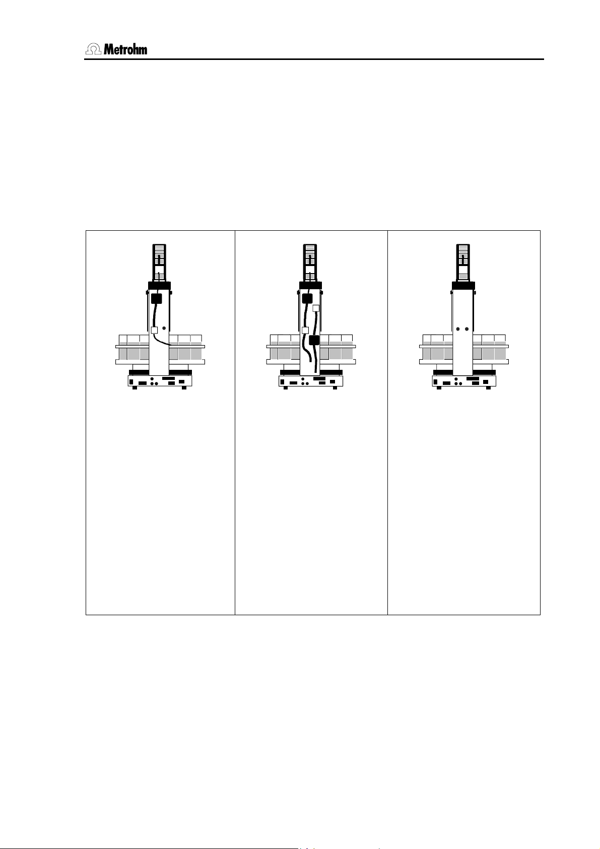
1.1.2 Instrument versions
Variously equipped Metrohm Sample Processors models are available:
• All versions of the 789 Robotic Sample Processor XL are suitable
for sample racks of up to 48 cm diameter.
• All versions of the 778 Sample Processor are suitable for sample
racks of up to 42 cm diameter.
Model 2.789.0010
Model 2.778.0010
1 tower with 1 pump
+ 1 ext. pump connection
+ 1 stirrer connection
+ 1 Swing Head connection
Chassis with 3 MSB sockets
for dosing devices and/or
stirrers
+ Remote connection
(25-pin)
+ RS232 connection (9-pin)
+ keyboard connection
Model 2.789.0020
Model 2.778.0020
1 tower with 2 pumps
+ 1 stirrer connection
+ 1 Swing Head connection
Chassis with 3 MSB sockets
for dosing devices and/or
stirrers
+ Remote connection
(25-pin)
+ RS232 connection (9-pin)
+ keyboard connection
Model 2.789.0030
Model 2.778.0030
1 tower without pumps
+ 2 ext. pump connections
+ 1 stirrer connection
+ 1 Swing Head connection
Chassis with 3 MSB sockets
for dosing devices and/or
stirrers
+ Remote connection
(25-pin)
+ RS232 connection (9-pin)
+ keyboard connection
Table 1 Model versions (1 tower)
Metrohm Sample Processor, Introduction 3
Page 12
1.1 Instrument description
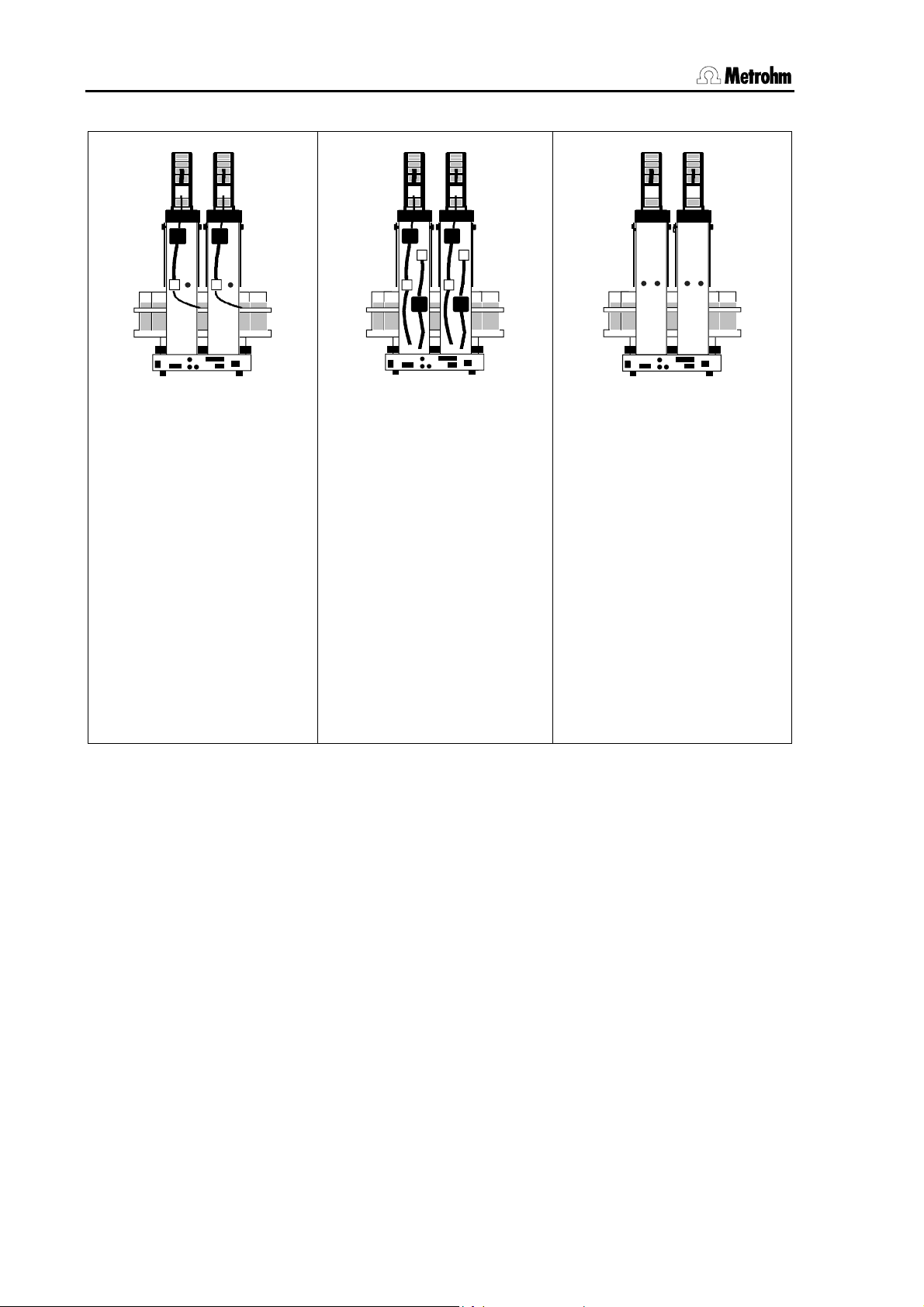
Model 2.789.0110
Model 2.778.0110
2 towers with 2 pumps
+ 2 ext. pump connections
+ 2 stirrer connections
+ 2 Swing Head connections
Chassis with 3 MSB sockets
for dosing devices and/or
stirrers
+ Remote connection
(25-pin)
+ RS232 connection (9-pin)
+ keyboard connection
Table 2 Model versions (2 towers)
Model 2.789.0120
Model 2.778.0120
2 towers with 4 pumps
+ 2 stirrer connections
+ 2 Swing Head connections
Chassis with 3 MSB sockets
for dosing devices and/or
stirrers
+ Remote connection
(25-pin)
+ RS232 connection (9-pin)
+ keyboard connection
Model 2.789.0130
Model 2.778.0130
2 towers without pumps
+ 4 ext. pump connections
+ 2 stirrer connections
+ 2 Swing Head connections
Chassis with 3 MSB sockets
for dosing devices and/or
stirrers
+ Remote connection
(25-pin)
+ RS232 connection (9-pin)
+ keyboard connection
4 Metrohm Sample Processor, Introduction
Page 13
1.2 Sample Processors as part of a system
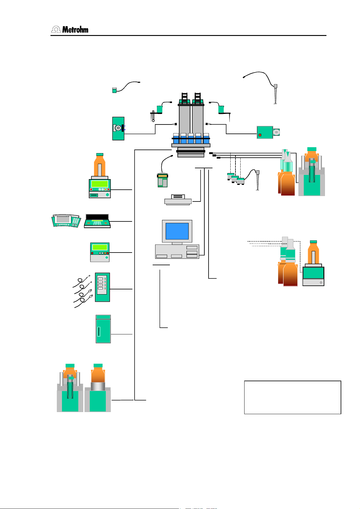
1.2 Sample Processors as part of a system
741 Magnetic
Stirrer
772 Pump Unit
Titrinos
781 pH/Ion Meter Metrohm781 pH/Ion Meter Metrohm
pH Meter / Ion Meter
756/831
756 KF
Coulometer
DC
731
AC
Relay Box
731 Relay Box
711 Liquino
711 Liquino
786 Swing Head*
772 Pump
Remote
Keypad
PC
COM 1
RS 232
786 Swing Head**
MSB
RS 232
801 Stirrer
804 Titation Stand
Printer
TiNet
PC
2.x
USB
COMx
COM 2
LPT 1
COM 2
Personal
Computer
• Titrinos
• pH Meter
• Coulometer
• other
Metrohm instruments
• other manu-
• Titrinos
• pH Meter
facturers instruments
• Coulometer
• other Metrohm instruments
• balance
• instruments from
other manufacturers
MSB
802 Rod Stirrer
823823
800
800
800
800
Dosino
Dosino
Dosino
Dosino
800 Dosino
805 Dosimat
700
700
Dosino
Dosino
Dosino
Dosino
700 Dosino
685 Dosimat
823 Membrane
Pump Unit
805 Dosimat805 Dosimat
700
700
685 Dosimat
786 Swing Head
809 Titrando809 Titrando808 Titrando808 Titrando
• other Metrohm
instruments
* with titration-robotic arm
** with transfer-robotic arm
Fig. 1 System components
Titrandos
(6.2148.010 Remote Box
required)
Metrohm Sample Processor, Introduction 5
Page 14
1.3 Information about these Instructions for Use
1.3 Information about these Instructions for Use
1.3.1 Please note
Please read through these Instructions for Use carefully before you
start to use the Sample Processor. The instructions contain information
and warnings that must be observed by the user in order to guarantee
the safe use of the instrument.
1.3.2 Additional documents
• Quick Reference 8.789.1013 for the Metrohm Sample Processors
• Operating Tutorial 8.789.1023 for the Metrohm Sample Processors
• Technical Reference 8.789.1033 for the Metrohm Sample Proces-
sors
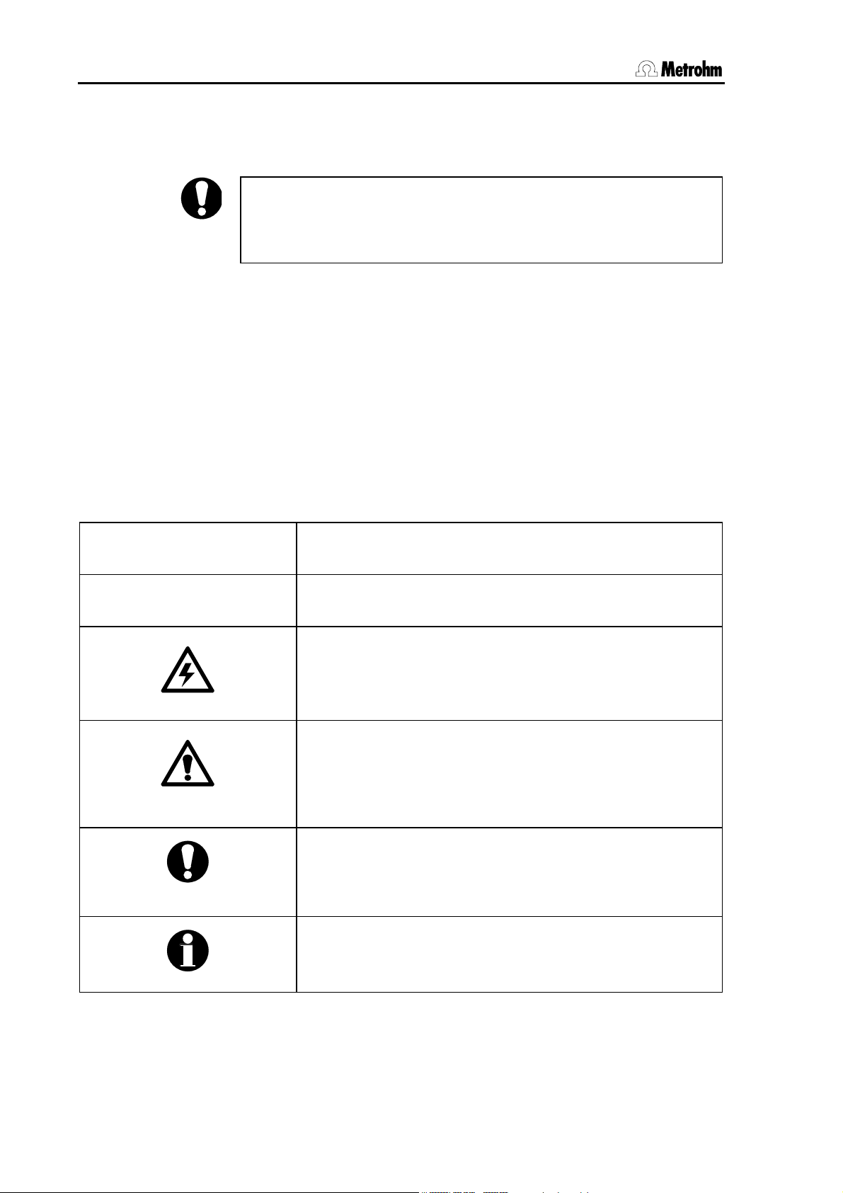
1.3.3 Notation and pictograms
The following notation and pictograms are used in these Instructions for
Use:
Location Menu item, parameter or input value
<OK> button, key
Danger
This symbol indicates a possible risk of death or injury to
the user if the instructions are not followed correctly.
Warning
This symbol indicates a possible risk of damage to the instruments or their components if the instructions are not followed correctly.
Attention
This symbol indicates important information. Read the information provided before you continue.
Remarks
This symbol indicates additional information and tips.
6 Metrohm Sample Processor, Introduction
Page 15
1.4 Parts and controls
1.4 Parts and controls
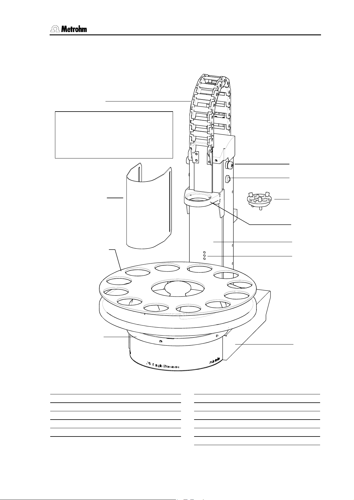
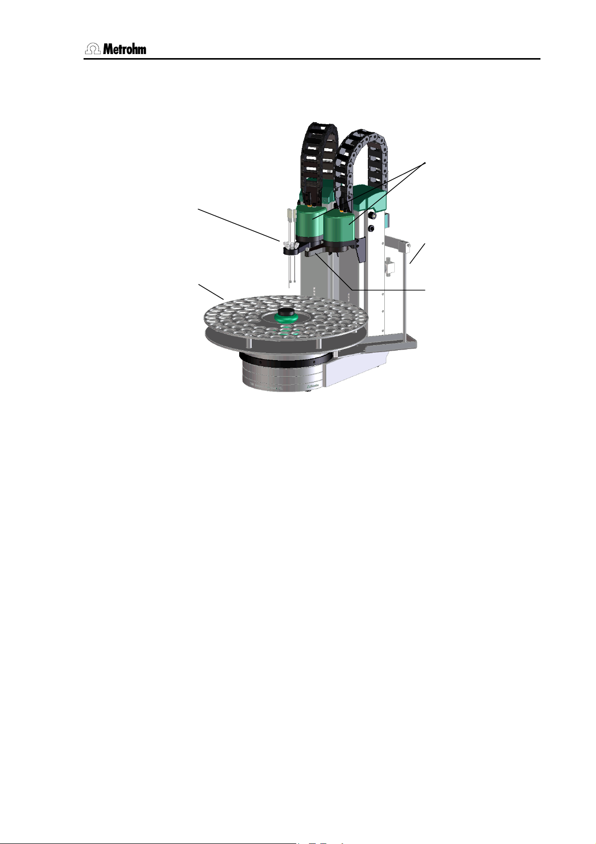
1.4.1 Overall view
1
Safety information
Safety shield 2 must always be in position before the Metrohm Sample
Processor is used.
5
6
2
3
4
Fig. 2 Overall view
7
8
9
10
11
Guide chain
1
Safety shield/Splash protection
2
Sample rack
3
Stirrer rail
4
Splash protection fixing
5
Metrohm Sample Processor, Introduction 7
6
7
8
9
10
11
Splash protection guide
Titration head
Lift
Tower
Beaker sensor
Chassis
Page 16
1.4 Parts and controls
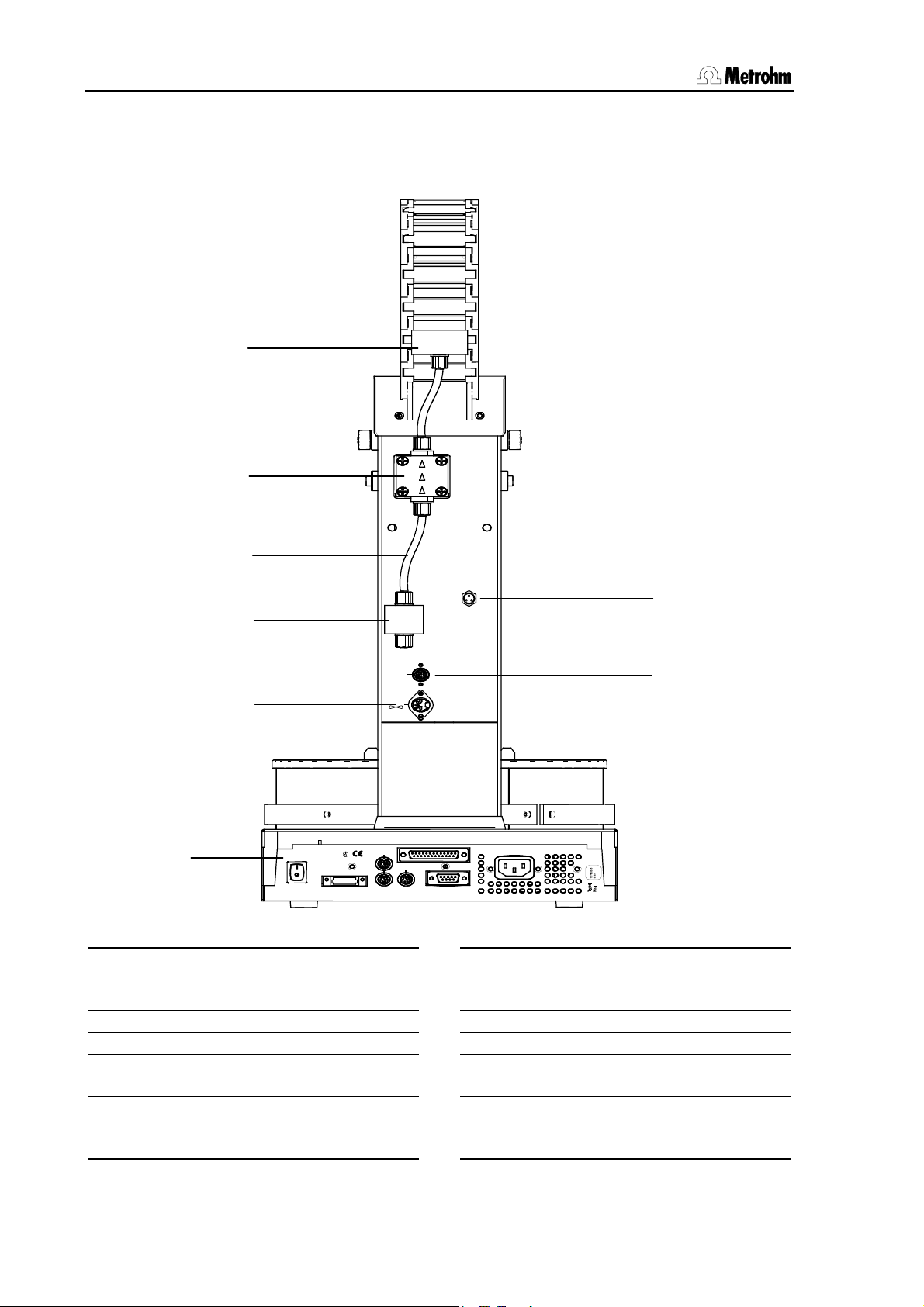
1.4.2 Rear view
This illustration shows the rear view of the standard model 2.778.0010 with
one tower, one membrane pump and one connection for an external pump.
12
13
Pump 1
17
Distributor block
12
Membrane pump
13
PTFE tubing
14
Solenoid valve
15
Warning: Biohazard
a
See Section
14
15
Swing
16
W
R
A
N
I
N
G
-
e
i
r
F
H
a
z
-
a
d
o
u
c
i
n
r
o
t
n
i
e
h
s
a
t
t
h
t
t
e
p
i
o
o
d
c
r
e
e
l
r
p
n
e
e
y
d
p
a
m
t
n
g
i
n
a
t
r
Made by Metrohm
Herisau Switzerland
r
a
l
y
c
e
n
o
s
f
e
u
f
o
Keyboard
MSB1
MSB2
F
w
Power
Fig. 3 Rear view
1.8.3 Personal protection
Head
Remote
RS 232
MSB3
16
17
18
19
b
Ext.
Pump 2
18
19
S: 115 VA
U: 100 - 240 V f: 50 - 60 Hz
Stirrer connection (Tower 1)
For 802 Rod Stirrer or
741 Magnetic Stirrer
Connection strip
Pump connection M8 (external)
Connection socket for the
786 Swing Head
Warning: Resistance to chemicals
See section
2.4.1 Connecting rinsing
and aspiration equipment
8 Metrohm Sample Processor, Introduction
Page 17
1.5 Connections
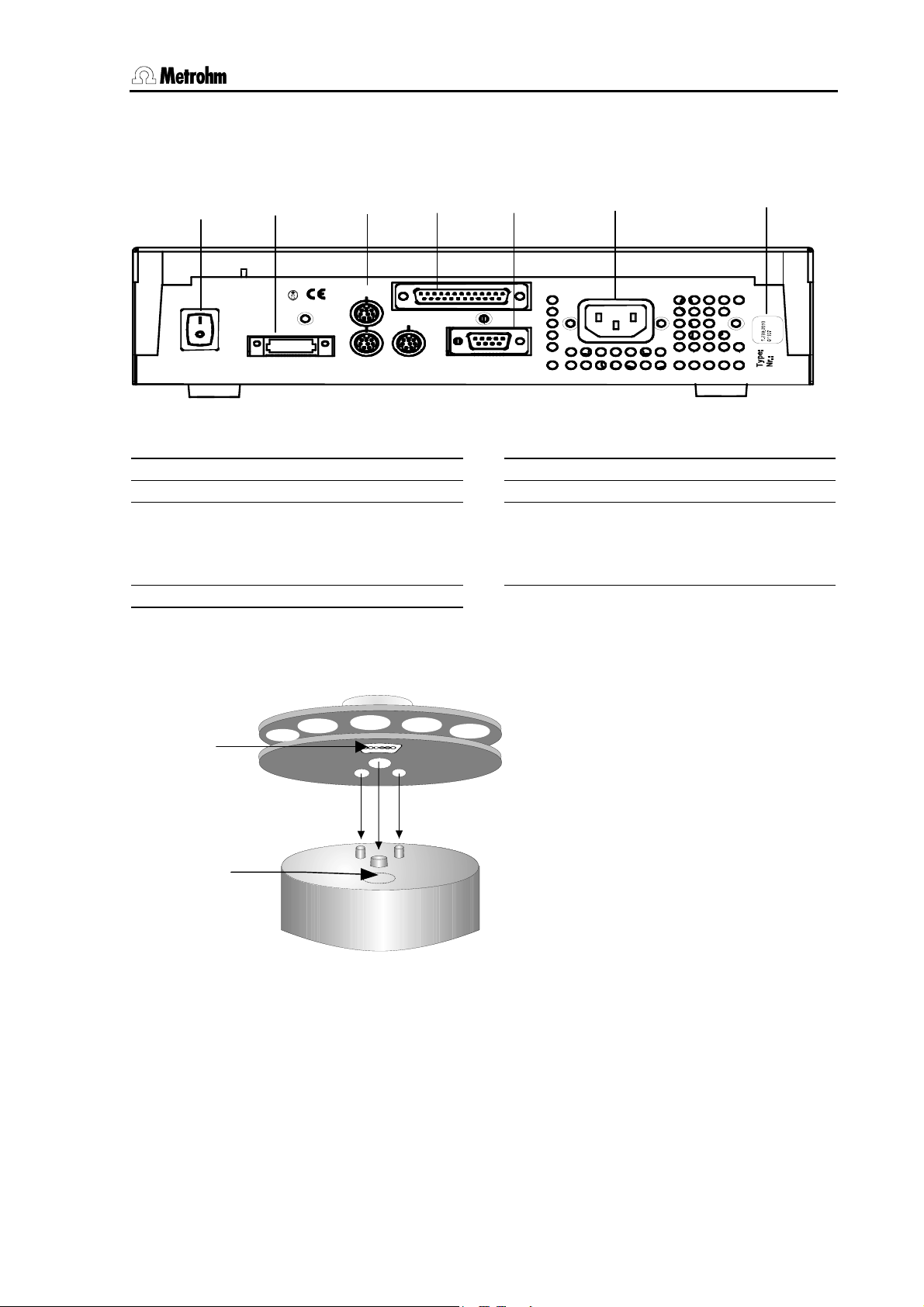
1.5 Connections
The electrical connections are the same for all models of the Metrohm
778/789 Sample Processor series.
21
W
R
A
N
-
I
G
N
F
e
i
r
H
a
z
-
a
d
t
e
c
a
t
n
i
o
n
a
r
d
e
r
l
a
p
c
e
o
f
o
g
i
n
t
f
u
r
l
y
n
s
e
Keyboard
MSB1
MSB2
c
o
r
o
F
n
w
i
t
t
h
e
h
Power
p
u
d
r
i
n
e
t
o
s
a
e
y
e
m
p
t
Made by M etrohm
Heris au Switzerland
Mains switch
20
Keyboard connection
21
MSB connections MSB1 … MSB3
22
Metrohm Serial Bus
Connection of dosing devices and stirrers
Remote connection (25-pin)
23
22
23 24
Remote
MSB3
RS 232
Fig. 4 Connection strip
24
25
26
25
S: 115 VA U : 100 - 240 V f: 50 - 60 Hz
26
Serial RS232 connection (9-pin)
Mains connection
Type plate
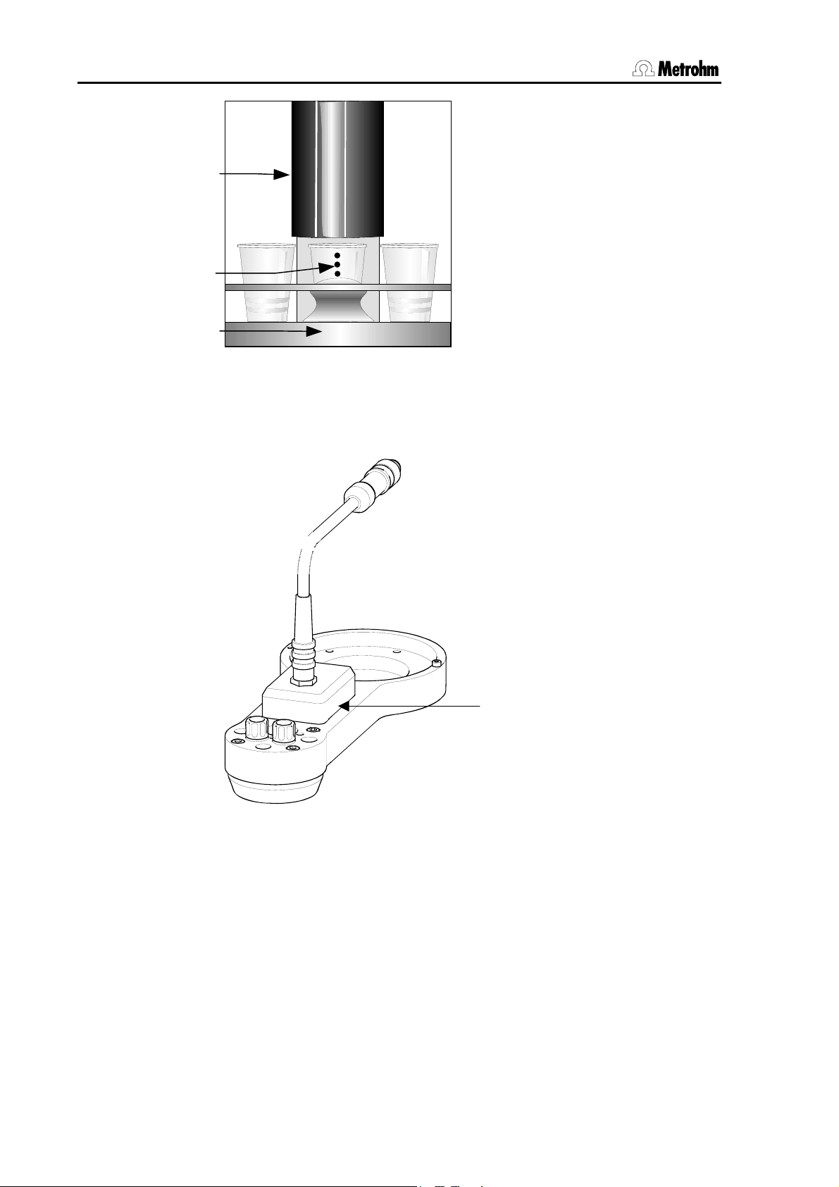
1.5.1 Sensors of the Sample Processor
Magnet holder
Magnet
sensor
Fig. 5 Magnet sensor for rack code
Rack sensor
The magnet sensor for recognizing
the individual rack code is located beneath the turntable of the Sample
Processor. The magnet code of a
rack can only be read in when the
rack is in the initial position. The magnet holder must be positioned directly
above the sensor.
For this reason the Sample Processor
should be initialized each time that a
rack is changed with the <RACK>
key.
Metrohm Sample Processor, Introduction 9
Page 18
1.5 Connections
/
k
Optical beaker sensor
Each tower of a Metrohm Sample
Splash protection
Safety shield
Beaker sensor
Sample rac
Fig. 6 Beaker sensor on the
tower
Processor is equipped with a beaker
sensor that detects the presence of
a beaker in front of the tower. With
this infrared sensor beakers made
from different materials can be detected, provided that they are located in the correct position in front
of the tower and the beaker sensor
'Tower' has been selected in the
rack definition. This "Beaker test" is
carried out after each MOVE command (i.e. each rotation of the rack).
The beaker sensor on the tower can
only be used with single-row sample
racks.
Tactile robotic arm sensor
Robotic arms with piezo sensors
may be used with multi-row racks.
The sensor is activated, when the lift
is run to work position and makes
physical contact with a sample
beaker.
Piezo sensor
Fig. 7 Sensor on a robotic arm
10 Metrohm Sample Processor, Introduction
Page 19
1.6 Accessories
k
1.6 Accessories
Robotic arm with
titration head
786 Swing Heads
Stand support
Sample rac
Robotic arm for
sample transfer
Fig. 8 Accessories
With suitable accessories a Sample Processor can be extended to form
a comprehensive automated system. Depending on the tasks to be
carried out, various standard components or even custom-made special parts can be used. Please consult the list of accessories on page
137ff.
Sample racks
Custom-made racks for various vessel sizes with any arrangement of
rack positions can also be supplied in addition to the standard racks.
786 Swing Head with robotic arm
The use of multi-row sample racks or external titration cells requires the
use of a 786 Swing Head. This motor drive, which is mounted on the lift
of one of the Sample Processor towers, can move different types of robotic arm. Various types of standard robotic arms with accessories for
titrating on the sample rack or for sample transfer to an external titration
cell are available.
Stand support
If an external titration cell is to be used then we recommend the use of
a stand support. The stand support can accommodate a magnetic stirrer (e.g. model 801) and, with a support rod, enables you to attach a titration cell or other accessories.
Metrohm Sample Processor, Introduction 11
Page 20

1.6 Accessories
Swing head with tactile piezo sensor
When using a multi-row rack and a 786 Swing Head, a robotic arm with
a touch-sensitive piezo sensor may be used. With that kind of sensor
the presence of a sample beaker can be detected reliably.
Robotic arm for removing covers
Whenever covered sample containers are required (e. g. with volatile
samples) the lids can be removed by a special robotic arm (so called
Dis-Cover) with magnetic contact before the sample treatment. Special
lids are available for this purpose.
Accessory set for sample transfer
For pipetting samples into external titration cells an accessory set
(6.5619.000) is available, comprising all necessary parts.
12 Metrohm Sample Processor, Introduction
Page 21
1.7 The keypad
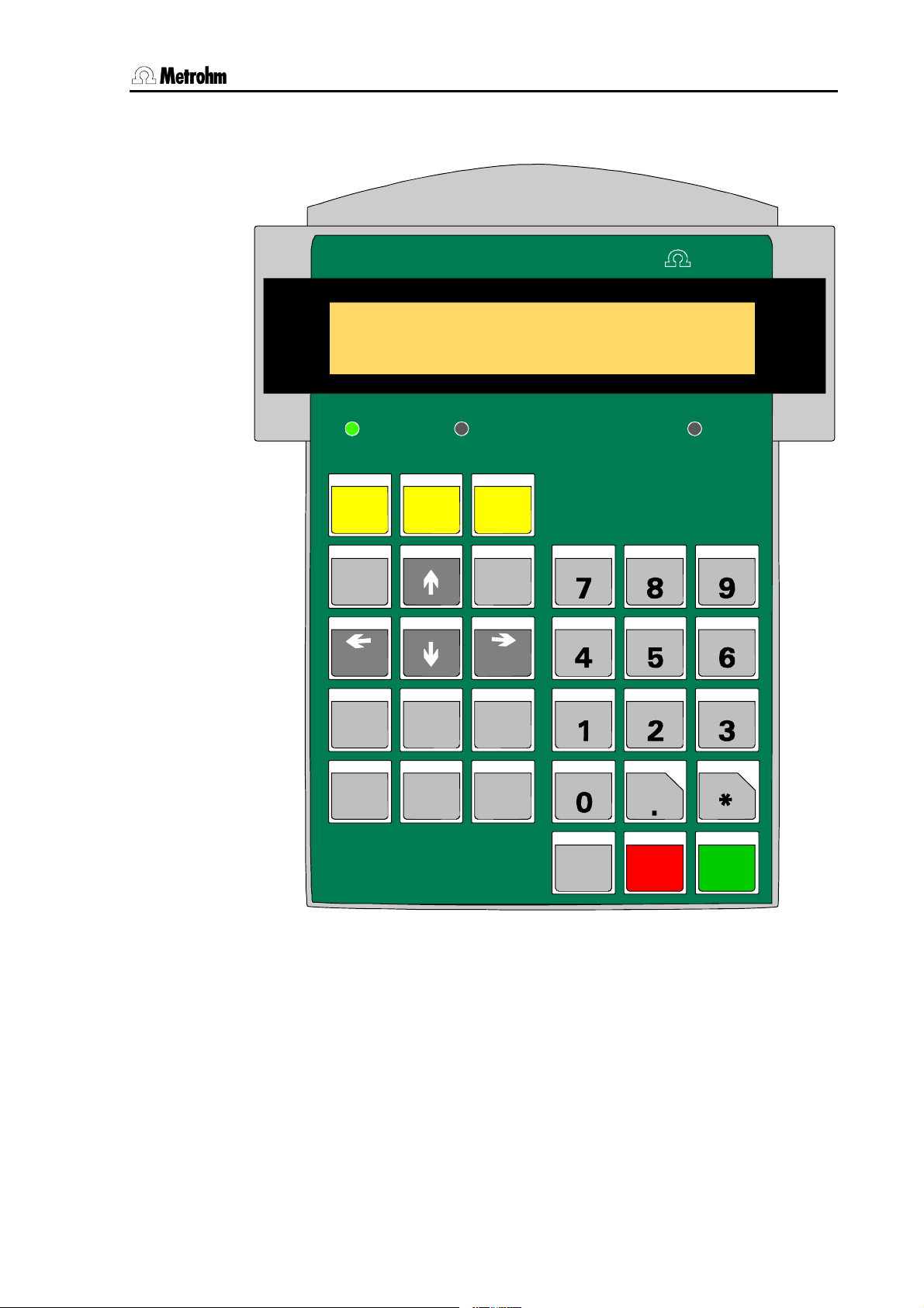
1.7 The keypad
Controller
********
PUMP---- STIR----
TOW ER 1 TOW ER 2 LEAR N
CONFIG PARAM
HOME END
NEXT
TOWER
counter
USER
METHOD
PREV
RESET
1/12
ready
-
SAMPLE MOVE LIFT
PUMP STI R DO S
SCAN CTRL WA IT
Met r ohm
INSERT
DELETE
6.2142.040
SELECT
QUIT ENTER
CLEAR
DEF
LEARN
HOLD
PRI NT
+
STOP
<
RACK
-
START
>
Fig. 9 Keypad
Below the 2-line display there are three LEDs. The two LEDs 'TOWER 1'
and 'TOWER 2' indicate the tower that is currently active. The LED
'LEARN' lights up when the learn mode is activated.
Most keys have two functions, depending on whether the Sample Processor is in the normal operating mode or in the editing mode.
Selection menus can be accessed with the upper row of keys (<CON-
FIG>, <PARAM>, <USER METHOD>). The other keys on the left-
Metrohm Sample Processor, Introduction 13
Page 22
1.7 The keypad
hand side of the keypad are used for navigation in the menus or for altering parameters. For entering parameters the numerical block on the
right-hand side of the keypad is also available.
The lowest row of keys (<HOLD>, <STOP>, <START>) are used
for the direct control of a method sequence.
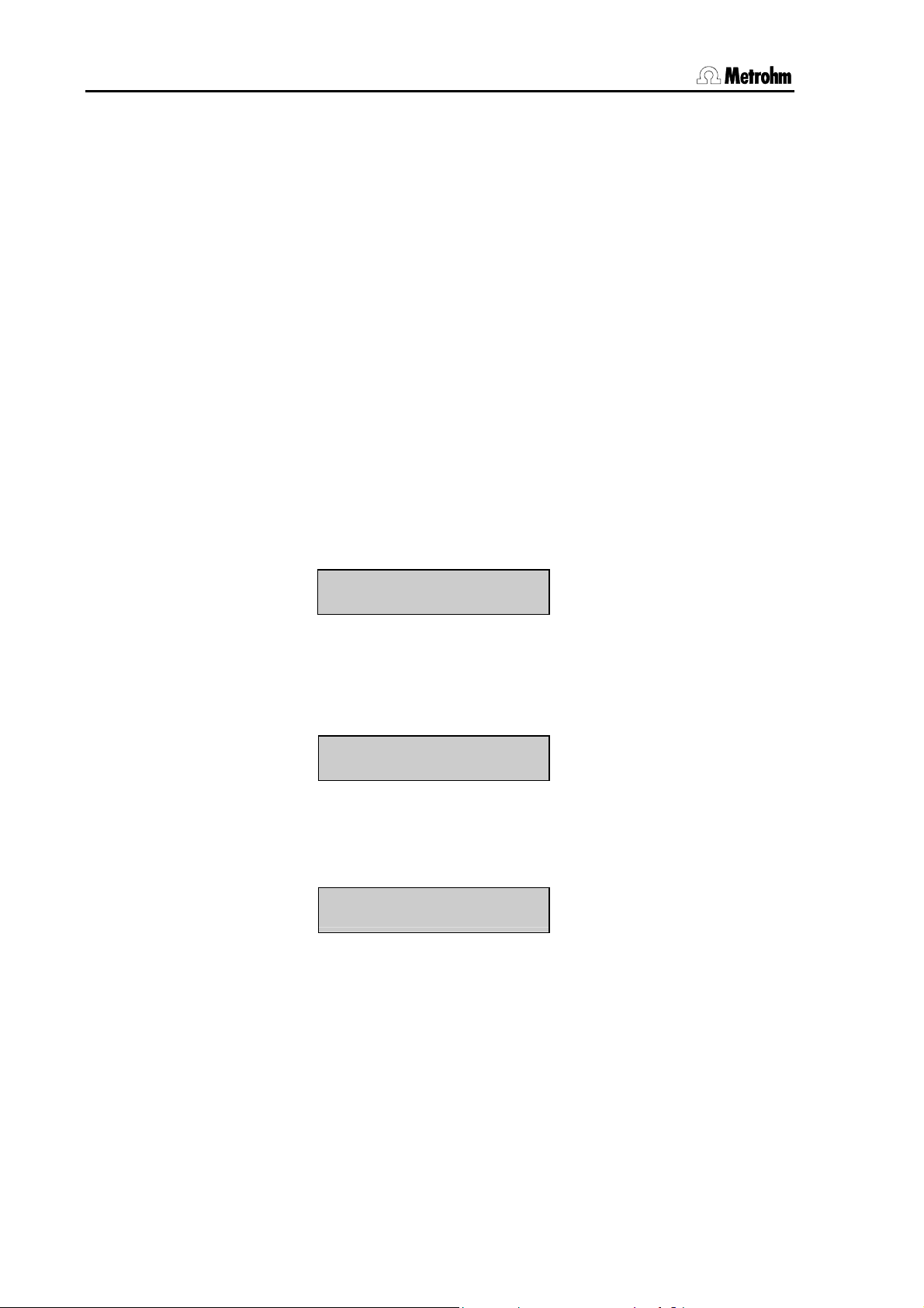
1.7.1 The display
The display consists of two lines each with 24 characters.
The first line is used as the title line, in which the current method and
the sample counter count are shown. In the editing mode the menu title
appears here.
The second line is used as the status line, which shows specific activities depending on the operating status. In the editing mode it is used as
the input line.
Normal condition
Method name
Pump status
Sample counter
******** counter 1/12
PUMP--++STIR+---- ready
Stirrer status
Method sequence
Running sequence
******** counter 2/12
START 03 WAIT 11 s
Current command with line number
Editing mode
Menu line or command
Menu title
>Sample sequence
1 MOVE 1 : Sample
st
1
parameter
If the Sample Processor is included in a computer-controlled automation system and is completely controlled via the RS232 interface then it
may be advisable to switch off the display. This can be done in the
setup menu of the Sample Processor, see p.
Instrument status
Parameter
nd
2
parameter
114.
14 Metrohm Sample Processor, Introduction
Page 23
1.7 The keypad
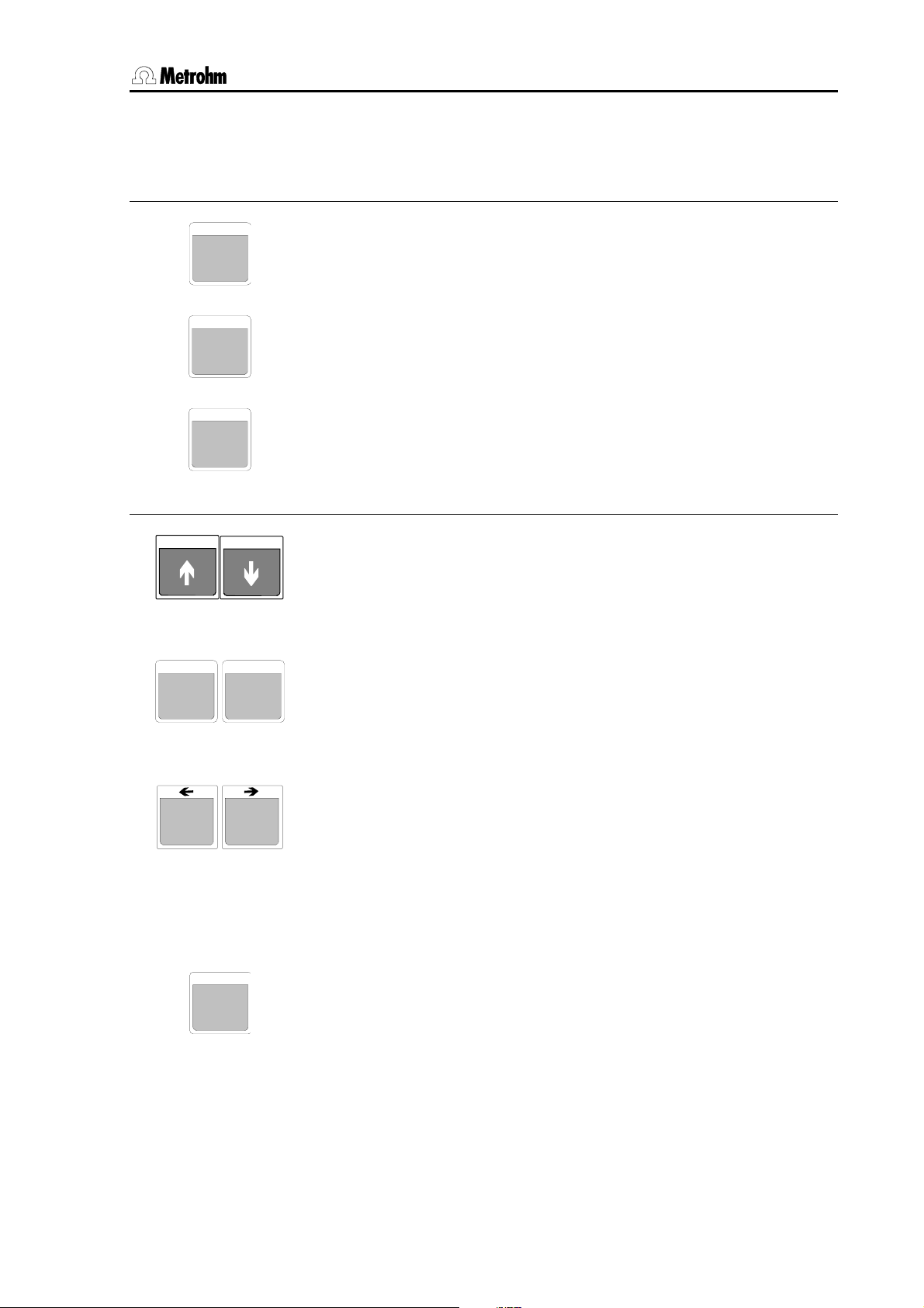
1.7.2 The keys
The menu keys
The <Config> key opens the selection menu for the configuration of
CONFIG
the Sample Processor.
The <PARAM> key opens the selection menu for editing the run se-
PARAM
quences and method parameters.
The <User Method> key opens the selection menu for opening, sav-
USER
METHOD
ing and deleting default or user-defined methods.
Lift operation and sample positioning keys
With the <> and <> keys the lift of the currently active tower can
be moved up and down respectively. The lowest possible lift position
is defined by the configuration parameter 'max. stroke path'.
In the editing mode the arrow keys <> and <> are used
for navigation in the particular menu or submenu.
HOME
NEXT
TOWER
SELECT
END
PREV
With the <HOME> key the lift of the currently active tower is returned
to the rest position (0 mm), i.e. to the uppermost stop.
<END> moves the lift to the predefined working position (see p.
In the editing mode the <HOME> and <END> keys move to
the first and last line of the menu or submenu respectively.
With the < NEXT> and < PREV> keys the sample rack can be
rotated forward or backward by one position. The beaker positions
depend on the active lift. If necessary, the lift (or both lifts) are automatically raised to the shifting position. When the rack position has
been reached a robotic arm which may be mounted will automatically
be directed to the corresponding rack position.
In the editing mode the arrow keys <> and <> are
used for navigation in a menu line.
Most functions for manual operation apply specifically to a single
tower. With the 2-tower models the <SELECT/TOWER> key can be
used to switch between the towers. The currently active tower is indicated by the TOWER 1 or TOWER 2 LED. The following commands
or keys refer to the active tower: MOVE, <>, <> , LIFT, <>,
<>, <HOME>, <END> and <PUMP>.
During data input the <SELECT> key is used to select a pre-
defined entry from a selection list.
61).
Metrohm Sample Processor, Introduction 15
Page 24
1.7 The keypad
Editing and sequence control
When editing a method sequence the <INSERT> and <DELETE>
INSERT DELETE
keys are used to insert or delete a command line.
RESET
CLEAR
QUIT
ENTE R
Command keys
SAMPLE
7
MOVE
8
The <CLEAR/RESET> key is used to initialize the Sample Processor
and dosing devices. This corresponds to the switching-on process.
During data input the <CLEAR/RESET> key is used to de-
lete an entry or to reset the default value. In text entry mode
the last character is deleted.
During a method sequence the <QUIT> key can be used to terminate the command which is currently being carried out. The following
command is executed.
During data input the <QUIT> key is used to terminate an en-
try. During navigation in a menu the <QUIT> key is used to
exit the active (sub)menu and select the next highest menu
level.
During data input the <ENTER> key is used to accept the entry.
The <SAMPLE> key is used to set the current sample position. This
has to be done before a sample series is run.
At the start of a method this position is assumed to be the first sample
in a series. If no sample position has been set then the Sample Processor will select rack position 1.
With <MOVE> a vessel or a particular rack position can be moved to
the active tower or a robotic arm can be swung to an external position.
The <SELECT> key is used to select the tower.
As well as the actual sample beaker a maximum of 16 possible special beakers can also be defined. A particular rack position can be
moved to directly by entering the position number (with the numerical
keys).
The direction and speed of rotation can be altered in the parameter
menu or with the <DEF> key.
Important:
For safety reasons it is only possible to rotate the sample rack when
the lift or both lifts are located in the shifting position or above it. During a rack rotation the lift (or both lifts) are automatically first raised to
the predefined shift height.
16 Metrohm Sample Processor, Introduction
Page 25

1.7 The keypad
LIFT
Raises or lowers the lift of the active tower. The predefined lift positions (working position, rest position, rinsing position, shifting position,
9
special position) can be selected with the <SELECT> key. They can
be entered and saved separately for each rack in the configuration
menu.
As well as the predefined lift positions it is also possible to enter absolute lift positions in mm via the numerical keys.
In the 2-tower models the tower can be selected with <SE-
LECT/TOWER>.
PUMP
The <PUMP> key is used for switching the pumps 1 or 2 of the active tower on and off. By entering the pump number (1 or 2) the condi-
4
tion of the corresponding pump will be switched, i.e. if the pump is
switched off it will be switched on and vice versa. With Sample Processor models that have no pump or only one built-in membrane pump
the selected pump connection will be switched on or off.
The status of all pumps is shown in the display (e.g.
PUMP–+–+; +
means switched on, - means switched off).
Example:
PUMP on/off No. ? <2> Display: PUMP -+--
PUMP on/off No. ? <2> Display: PUMP ----
In this case pump 2 is switched on and off.
Under <PARAM>,
>manual stop you can define whether the pumps
should be switched off with the <STOP> key or not.
STIR
The <STIR> key is used for controlling the stirrers. A stirrer can be
switched on permanently or switched on for a given period and then
5
switched off again. The <SELECT> key is used to select both the
stirrer and the function. The current status of the stirrer is shown directly in the display.
Example:
STIR: T1 : ON s Display: STIR +- (+=on -=off)
STIR: MSB2 : 10 s Display: STIR 10 s
In this case in the first line the stirrer at tower 1 is switched on. The stirrer is selected with the <SELECT> key. As can be seen in the sec-
ond line, the duration of the stirring process can also be entered.
The stirring rate can be set for each stirrer in the parameter menu or
with the <DEF> key.
Under <PARAM>,
>manual stop you can define which stirrers can
be switched off with the <STOP> key.
DOS
The <DOS> key is used to control the connected dosing devices.
Both positive and negative volumes can be dosed. Negative volumes
6
are used for aspirating liquids, e.g. during pipetting.
As well as entering the volume to be dosed (with the numerical keys),
Metrohm Sample Processor, Introduction 17
Page 26

1.7 The keypad
<SELECT> can also be used to select additional functions:
- Filling the dosing or exchange unit (fill)
- Initializing the escange of a Dosing unit (release)
- Preparing the tubing systems and cylinder (prep.)
- Emptying the tubing system and the dosing cylinder (empty)
- Ejecting the cylinder contents (Eject)
- Driving the piston to the max. volume
- Compensating for the play between piston and spindle (compen.)
- Valve switching (port)
The first parameter of the DOS command stands for the number of the
dosing instrument (1…3, * = all) and the Dosino port (e. g. 1.1 stands
for Dosino 1, port 1), the second parameter for the function or the volume to be dosed.
Example:
DOS: 2.1 <ENTER> 4.51 ml <ENTER>
DOS: 2.* <ENTER> <SELECT> ... fill <ENTER>
The dosing and filling rates can be set in the parameter menu or with
the <DEF> key.
SCAN
Shows the incoming signals or data from the Remote or the serial
RS232 interfaces.
1
This function is used for checking the data communication with connected devices.
The first parameter shows the selected interface. The second parameter shows the signals or data that are received directly.
If the parallel Remote interface (Rm) is selected then the signal states
of the incoming Remote lines are shown in binary form (1=line active,
0=line inactive).
If the serial RS232 interface (RS) is selected then the data string received via this interface will be shown (14 characters per line).
Example (Remote interface):
SCN:Rm :00000001
In this case the Ready line (Remote line input 0) of a connected Titrino is set.
CTRL
Controls external devices via the Remote or RS232 interface.
The first parameter sets the interface (<SELECT>). The second pa-
2
rameter defines the status of the lines (Remote lines) or data (RS232
interface) to be outputted via the selected interface.
2nd parameter, for Remote interface
Binary pattern with 14 digits (0, 1 or ∗) for the 14 output lines or prede-
18 Metrohm Sample Processor, Introduction
Page 27
1.7 The keypad
WAIT
3
DEF
0
DEF settings
DEF
0
DOSRATE
fined binary pattern (<SELECT> selection), e.g.
INIT etc.
START device 1,
2nd parameter, for RS232 interface
Data string with up to 14 alphanumeric characters (any).
The default value "&M;$G" (for starting Metrohm instruments) can be
set with <CLEAR>.
The <WAIT> key has no function in the normal operating condition. It
is used to insert the WAIT command in a run sequence.
The <DEF> key is used to edit various settings for manual operation. Repeated pressing of the <DEF> key is used to select the various settings. In order to change the entry you must first press
<ENTER> and then enter the new value.
Alterations made in this way only apply to manual operation.
Change dosing rate
• The dosing rate in mL/min can be set separately for each dosing
device, see p.
• Syntax:
DOSRATE [dosing device] [dosing rate]
70.
COCKMOVE
DEF
0
FILLRATE
DEF
0
DEF
0
LIFTRATE
Change filling rate
• The filling rate in mL/min can be set separately for each dosing
device, see p.
• Syntax:
FILLRATE [dosing device] [filling rate]
70.
Direction of stopcock rotation
• For each connected Dosino the direction of rotation of the stopcock switching can be defined separately, see p.
• Syntax:
COCKMOVE [Dosing device] [Direction of rotation]
70.
Change lift rate
• The lift speed in mm/s can be set separately for each tower (for 2tower models), see p.
• Syntax:
LIFTRATE [Tower] [Lift rate]
68.
Metrohm Sample Processor, Introduction 19
Page 28
1.7 The keypad
SHIFTRATE
SWINGRATE
STIRRATE
DEF
0
DEF
0
DEF
0
Change rack rate and direction of rotation
• As well as the speed of rotation of the sample rack in degrees/second the direction of rotation can also be defined.
• Direction of rotation "+" means that the rack always rotates coun-
terclockwise, i.e. in increasing rack position sequence, Direction
of rotation "–" means clockwise, i.e. decreasing sequence.
• Direction of rotation
shortest possible path for a rack rotation, see p.
• Syntax:
SHIFTRATE [Direction of rotation] [Rotation rate]
auto: the Sample Processor itself selects the
68.
Change swing rate
• The swing rate in degrees/s of a robotic arm can be set separately for each connected 786 Swing Head, see p.
• Syntax:
SWINGRATE [Tower] [Swing rate]
68.
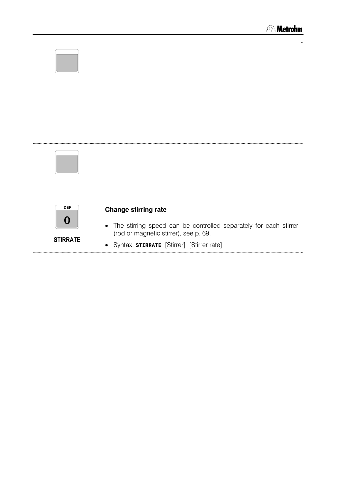
Change stirring rate
• The stirring speed can be controlled separately for each stirrer
(rod or magnetic stirrer), see p.
• Syntax:
STIRRATE [Stirrer] [Stirrer rate]
69.
20 Metrohm Sample Processor, Introduction
Page 29

1.7 The keypad
Auxiliary commands
PRINT
<
.
RACK
>
-
*
The <PRINT> key is used to print out a report. The following can be
selected: parameter report (method), configuration report, list of
stored methods, all reports.
The type of report can be selected with <SELECT>.
e. g.
Print: config
The selection of the printer type and the settings of the RS232 interface must be made in the configuration menu under
tings, see p. 37.
>RS232 Set-
With the <RACK> key the sample rack can be initialized. The connected peripheral devices (e.g. Dosimats, Dosinos) are not affected
by this.
The sample rack and lift (both lifts in 2-tower versions) are moved to
the zero position and automatic rack recognition is carried out.
Metrohm Sample Processor, Introduction 21
Page 30

1.7 The keypad
Sequence control
The <START> key starts a method. A start is only possible when the
START
Sample Processor is in the normal operating condition, i.e. when the
display shows
ready.
If <START> is activated after an interruption (<HOLD>, see below),
then the sequence continues with the next command.
The <START> can also be used to carry out a single command line
in a run sequence (TRACE function), see p.
114.
The <STOP> key ends a method.
STOP
If a sample series is stopped manually with <STOP> then the final
sequence of a method will not be carried out. When the <STOP> key
is pressed the functions listed in the parameter menu under
stop will be carried out.
>manual
LEARN
HOLD
The <HOLD> key interrupts a method sequence.
Connected peripheral devices (Titrinos, etc.) will not be stopped
automatically. Only the method sequence will be interrupted. In the
HOLD condition a method can be completely terminated with
<STOP> or continued with <START>.
After an error message in the method sequence the Sample Processor switches automatically to the HOLD condition after <QUIT>.
22 Metrohm Sample Processor, Introduction
Page 31

1.8 Safety information
1.8 Safety information
Warning!
This instrument should only be used in accordance with the information
given in these Instructions for Use.
1.8.1 General:
This instrument left our works in perfect condition from the point of view
of its operational safety (see Technical data, safety specifications). To
keep it in this condition and to continue to operate safely the following
information must be carefully observed.
1.8.2 Electrical safety
Please observe the following guidelines:
• Only qualified Metrohm personnel should carry out service work on
electronic components.
• Do not open the instrument housing as this could damage the instrument. The housing contains no components which could be
serviced or exchanged by the user.
Electrical safety when handling the instrument is guaranteed within the
scope of Standard IEC 61010-1.
• Protection against electrostatic charges
Warning!
Electronic components are sensitive to electrostatic charges and can
be destroyed by a discharge. Before touching any electronic components of the Sample Processor one should ground himself and his tools
by grasping a grounded object (e.g. the instrument housing or a radiator) in order to eliminate any electrostatic charges that may be present.
• Mains connection
This instrument must only be operated at the specified mains voltages
(see rear panel of instrument).
• Opening a Sample Processor
When the Sample Processor is connected to the mains supply the instrument must not be opened, nor should any of its components be
dismantled as otherwise one could come into contact with currentcarrying components. Before opening the instrument it must be separated from all current sources. The mains cable has to be removed
from the mains connection socket!
Metrohm Sample Processor, Introduction 23
Page 32

1.8 Safety information
1.8.3 Personal protection
The different drives of the Sample Processor and the 786 Swing Head
possess considerable force in order that they can freely move even under heavy loads. They are fitted with electronic overload limiters that are
triggered if the mechanical resistance is too high.
When the instrument is running do not intrude in the working range
of the Sample Processor.
For the user there is a considerable risk of injury from manual in-
terference with the automatic processes of the instrument.
LEARN
HOLD
Running methods and individual commands can be interrupted with
the <HOLD> key and then continued with <START>.
Emergency stop
STOP
The <STOP> key always terminates all running processes immedi-
ately (exception: initialization during switch-on).
Important!
Before you use the instrument for the first time you must install the
included 6.2751.0xx Safety Shield, see p.
The Sample Processor must not be operated without the Safety
48.
Shield in position!
Fig. 10 Safety Shield
(example shown: 6.2751.0xx for transfer robotic arm)
Biohazard
The Sample Processor does not provide sufficient protection when
processing potentially infectious samples or reagents.
In this case install the necessary safety devices.
24 Metrohm Sample Processor, Introduction
Page 33

2.1 Installation flow chart
2 Installation
This section described the installation of all the components of a Sample
Processor and shows how it is connected to other instruments. Please
read through the following sections carefully and follow the instructions
in detail.
2.1 Installation flow chart
The following flow chart provides an overview of all the necessary installation work. Detailed information can be found in the given sections.
Setup Section
2.2
Connecting the mains cable Section 2.2.2
Connecting the keypad Section 2.2.3
* Mounting a 786 Swing Head Section 2.2.4
* Mounting a robotic arm Section 2.2.5
* Connecting the pumps Section 2.2.6
* Connecting a dosing device Section 2.2.7
Connecting the connection cables Section 2.3
Setting up the titration accessories Section 2.4.3
* Mounting the stand support Section 2.4.8
Mounting the safety shield Section 2.4.11
* optional
Metrohm Sample Processor, Installation 25
Page 34

2.2 Instrument setup
2.2 Instrument setup
2.2.1 Setup
Packaging
A Metrohm Sample Processor and its specially packed accessories are
supplied in very protective special packaging consisting of shockabsorbing plastic foam. Please store this packaging in a safe place; it is
the only way in which the safe transport of the instrument can be guaranteed.
Checks
Please check that the delivery is complete and undamaged immediately on receipt (compare with delivery note and list of accessories
given in Section
fer to the information given in Section
Location
6.3, p. 137). If transport damage is evident please re-
6.4.1 "Warranty", p. 162.
The Sample Processor is a robust instrument and can therefore be
used even in rough surroundings in laboratories and factories.
However, please ensure that it is not exposed to a corrosive atmosphere. The instrument should be serviced at regular intervals, particularly when operated under rough conditions.
2.2.2 Mains connection
This instrument must only be operated at the specified mains voltages
(see rear panel of instrument).
Protect the connection sockets against moisture.
Mains connection 25
S: 115 VA U: 100 - 240 V f: 50 - 60 Hz
26 Metrohm Sample Processor, Installation
Page 35

2.2 Instrument setup
A
2.2.3 Connecting the keypad
778
789
2.2.4 Mounting a 786 Swing Head
The procedure for the installation of the 786 Swing Head is described
below. This is normally carried out by the service technician.
The keypad is attached to the keyboard socket provided for it on the
rear panel of the instrument. To remove the plug press both sides together.
ttachment plate
Fig. 11 Mounting the Swing Head
For Sample Processors with 2 towers Tower 1 is moved to a central lift
position and Tower 2 to the parking position.
Switch off the instrument at the mains switch.
• Loosen the titration head holder fitted as standard from the lift
guide by removing the four side-mounted screws.
• Loosen the attachment plate from the titration
head holder and remove the holder.
• Screw the Swing Head onto the attachment
plate with the 2 delivered mounting screws.
• Mount the Swing Head on the lift guide.
786 Swing Head
Lift guide
Titration head holder
Metrohm Sample Processor, Installation 27
Page 36

2.2 Instrument setup
Swing
Head
Connecting to the Swing Head connection socket
Lead the connection cable of the 786 Swing Head through the guide
chain of the tower and connect the mini-DIN plug of the Swing Head
connection cable to the Swing Head socket on the rear panel of the
tower.
Configuring the Swing Head and robotic arm
As each type of robotic arm has its own dimensions, it is essential to
adapt the Swing Head setup settings to suit the particular type of robotic arm.
The necessary alterations are made in the setup dialog, see Section
3.13. The individual settings affect:
• Swing offset (default: 0°)
• Max. swing angle (default: 84°)
• Swing radius (=length of robotic arm, default: 110 mm)
• Swing direction (default Tower1: –, default Tower 2: +)
The setup dialog of the Sample Processor is opened by pressing the
<CONFIG> key as the instrument is switched on. A short explanation
is given in Section
3.13. Details about the individual settings and types
of robotic arm can be found in the Instructions for Use of the 786 Swing
Head.
2.2.5 Mounting the robotic arm
Certain robotic arms can, depending on the model, be mounted so that
they swing to the right or the left. During the mounting process the location of the limiting screw of the robotic arm must be taken into account.
Limiting screw
(for swing-right mounting)
Limiting screw
(for swing-left mounting)
Fig. 12 Robotic arm with limiting screw
Swing-right mounting means: The robotic arm can swing from the
zero-axis (center of the rack) to the right, as seen from the front. The
swing direction has to be set to '–'.
28 Metrohm Sample Processor, Installation
Page 37

2.2 Instrument setup
Robotic arms that can be mounted in two different ways (e. g.
6.1462.050) can have the limiting screw positioned according to the required swing direction (see above).
Mounting procedure
The 786 Swing Head must already be in position and configured before
the robotic arm can be mounted.
• Switch the instrument off and then on again. Wait
until the Swing Head drive has finished the initialization movements.
• Carefully push the robotic arm over guide cam 10
from below (see drawing). Hold the robotic arm in
such a way that limiting screw 9 points toward the
tower of the Sample Processor while the robotic
arm assumes the maximum swing angle.
10
9
Fig. 13 Mounting the robotic arm
Details about the individual robotic arm types can be found in the Instructions for Use of the 786 Swing Head.
2.2.6 Connecting pumps
On the Sample Processor models with one built-in membrane pump
one external pump per tower can be connected and controlled. The
models with no pumps even have two connections for external pumps.
Ext.
Pump 2
The pump connections (for 3-pin M8 connectors) on the rear panel of
the Sample Processor tower supply a feed voltage of 16 V for a max.
load of 600 mA.
Suitable pump models are:
• Use the three enclosed screws to attach the robotic
arm from below.
• Switch the instrument off and on again.
• Metrohm 823 Membrane Pump Unit (membrane pump, suitable for
aqueous media without particles)
• Metrohm 772 Pump Unit (peristaltic pump, suitable for organic solvents and aqueous solutions containing particles)
Metrohm Sample Processor, Installation 29
Page 38

2.2 Instrument setup
2.2.7 Connecting dosing devices and stirrers
Metrohm Sample Processors have various connections to which dosing
devices and stirrers can be connected.
Stirrers
The 722/802 Rod Stirrers and 741 Magnetic Stirrer have a DIN
connector and are connected to the rear panel of a tower (Tower stirrer
T1 and T2).
As with other Metrohm instruments, e. g. Titrandos, the three MSB
connectors (MSB = Metrohm Serial Bus) are very versatile. You can
connect an 801 Stirrer or an 804 Ti Stand to them.
Dosing devices
Up to three 700/800 Dosino or 685/805 Dosimat type dosing drives
can be operated by connecting them directly to the MSB sockets of a
Sample Processor. One 800 Dosino or 805 Dosimat can also be connected to the MSB output connector of another instrument connected
to the MSB socket, such as the 801 Stirrer, in a so-called 'daisy chain'.
Please note that only one instrument of a particular type may be present in such a daisy chain, e. g. a 801 Stirrer and a 805 Dosimat.
A 700 Dosino or a 685 Dosimat must be connected directly to the
MSB socket of the Sample Processor.
Dosing device and
stirrer connections
MSB1…3
The instrument will only recognize automatically a connected dosing
device when it is switched on or after RESET.
MSB1
Remote
MSB2
MSB3
Fig. 14 MSB connections
RS 232
30 Metrohm Sample Processor, Installation
Page 39

2.3 Data transmission connections
2.3 Data transmission connections
Connection cables
Only Metrohm cables should be used to connect a Metrohm Sample
Processor to other instruments. Only these will guarantee interferencefree data transmission.
Note:
The Remote cables for Metrohm Sample Processors and Sample
Processors have markings at each end of the cable to indicate the instrument that the particular connector is intended to be used with and
the connection into which it is to be plugged.
Example:
Titrino B
692 / 712 / 713
Fig. 15 Remote cable
The Sample Processor must be switched off before peripheral devices
are connected, as otherwise the instruments could be damaged.
2.3.1 Remote connections
In order to connect Remote cables to Titrandos and the 780/781
pH/Ion Meter an 8.2148.010 Remote Box is required as an additional
adapter; this is connected to one of the MSB sockets (MSB1…4), see
above.
Sample Processor — Titrino / Titrando
with standard cable (and 6.2148.010 Remote Box)
B
A
778
789
Titrino
C
D
778
789
6.2148.010
MSB
Titrando
Cable 6.2141.020
Metrohm Sample Processor, Installation 31
Cable 6.2141.020
Page 40

2.3 Data transmission connections
Titrinos and Titrandos can be connected to a Sample Processor in the
same way and can also be controlled.
Control commands:
CTL:Rm : START Device1 starts Titrino/Titrando
CTL:Rm : *************1 "
Final scan:
SCN:Rm : End1 waits for end of titration (EOD-impulse)
SCN:Rm : ****1*** "
SCN:Rm : Ready1 waits until Titrino/Titrando is ready
SCN:Rm : *******1 "
Sample Processor — pH / Ion Meter / Conductometer (692/712/713)
778
789
692
712
713
Control commands:
CTL:Rm : START device1 starts instrument
CTL:Rm : *************1 "
CTL:Rm : METER Mode pH switches to pH measurement
CTL:Rm : *********0001* " (not for 712)
CTL:Rm : METER Mode T switches to temp. measurement
CTL:Rm : *********0010* " (not for 712)
CTL:Rm : METER Mode U switches to mV measurement
CTL:Rm : *********0011* " (not for 712)
CTL:Rm : METER Mode I switches to Ipol (mV measurement)
CTL:Rm : *********0100* " (not for 712)
CTL:Rm : METER Mode C switches to Conc measurement
CTL:Rm : *********1000* " (for 692/781 only)
CTL:Rm : METER Cal pH switches to pH calibration
CTL:Rm : *********0101* " (not for 712)
CTL:Rm : METER Cal C switches to Conc calibration
CTL:Rm : *********1001 " (for 692/781 only)
Cable 6.2141.020
32 Metrohm Sample Processor, Installation
Page 41

2.3 Data transmission connections
CTL:Rm : METER enter simulates <ENTER> key
CTL:Rm : *********1111* " (not for 712)
Final scan:
SCN:Rm : End1 waits for end of measurement
SCN:Rm : ****1*** "
Sample Processor — 780/781 pH / Ion Meter
778
789
6.2148.010
MSB
Cable 6.2141.020
Control commands: see above (692/712/713 pH/Ion meter/ Conductometer).
Sample Processor — 781 Ion Meter — 665 Dosimat
For ion measurements with calibration and standard addition.
778
789
6.2148.010
A
765
D
B
C
MSB
Cable 6.2141.070
The 781 Ion Meter automatically controls Stirrer T1 of the Sample Processor.
Metrohm Sample Processor, Installation 33
Page 42

2.3 Data transmission connections
Start commands:
In principle these are the same commands as those given in the previ-
ous section.
Final scan:
In principle these are the same commands as those given in the previous section, with the addition of:
SCN:Rm : EndMeter waits for end impulse from 781
SCN:Rm : ***11*** "
Sample Processor— 2 x Titrino/Titrandos
778
789
Device 1
B
A
Titrino
C
D
Device 2
B
A
Titrino
C
D
Cable 6.2141.030
Control commands:
CTL:Rm : START Device1 starts Titrino/Titrando 1
CTL:Rm : *************1 "
CTL:Rm : START Device2 starts Titrino/Titrando 2
CTL:Rm : ********1***** "
CTL:Rm : START Device* starts both Titrino/Titrandos
CTL:Rm : ********1****1 "
Final scan:
SCN:Rm : End1 waits for end of titration Titrino/Titrando 1
SCN:Rm : ****1*** "
SCN:Rm : End2 waits for end of titration Titrino/Titrando 2
SCN:Rm : *1****** "
SCN:Rm : Ready1 waits until Titrino/Titrando 1 is ready
SCN:Rm : *******1 "
SCN:Rm : Ready2 waits until Titrino/Titrando 2 is ready
SCN:Rm : **1***** "
SCN:Rm : Ready* waits until both Titrino/Titrandos are ready
SCN:Rm : **1****1 "
The combined operation of the Titrino/Titrando/pH meter can also be
carried out without any problems by the same means.
34 Metrohm Sample Processor, Installation
Page 43

2.3 Data transmission connections
Sample Processor — Titrino/Titrando/pH Meter — 665/725 Dosimat
B
778
789
A
Titrino
C
D
A
765
D
B
C
Cable 6.2141.040
Control commands:
CTL:Rm : START Device1 starts Titrino
CTL:Rm : *************1 "
CTL:Rm : START Dos1 starts Dosimat 1
CTL:Rm : *******1****** "
Final scan:
SCN:Rm : End1 waits for end of titration (impulse)
SCN:Rm : ****1*** "
SCN:Rm : Ready1 waits until Titrino is ready
SCN:Rm : *******1 "
Sample Processor — Titrino/Titrando/pH Meter — 2x 665/725 Dosimat
B
778
789
A
C
D
Tit rino
A
D
B
C
A
765
765
D
B
C
Cable 6.2141.050
Control commands:
CTL:Rm : START Device1 starts Titrino
CTL:Rm : *************1 "
CTL:Rm : START Dos1 starts Dosimat 1
Metrohm Sample Processor, Installation 35
Page 44

2.3 Data transmission connections
CTL:Rm : *******1****** "
CTL:Rm : START Dos2 starts Dosimat 2
CTL:Rm : *****1******** "
CTL:Rm : START Dos* starts Dosimat 1 and 2
CTL:Rm : *****1*1****** "
Final scan:
SCN:Rm : End1 waits for end of titration (impulse)
SCN:Rm : ****1*** "
SCN:Rm : Ready1 waits until Titrino is ready
SCN:Rm : *******1 "
36 Metrohm Sample Processor, Installation
Page 45

2.3 Data transmission connections
2.3.2 Serial connections (RS232)
Many different connection to the RS232 interface are possible. As well
as all Metrohm instruments which understand the Metrohm Remote
language (see 'Technical Reference 8.789.1033'), a printer (requirement: serial interface or parallel/serial converter) or a personal computer can be connected. Instruments from other manufacturers that
have a serial RS232 interface can also be connected.
BA
Titrino
C
D
Cable 6.2143.040
Printer cable, see next page but one
Fig. 16 RS232 connections
A precondition for correct data transmission is that the transmission parameters are set correctly, these must correspond to the interface settings of the connected instrument (see next page).
The following section provides information about the settings and cables required for the connection of a printer.
Metrohm Sample Processor, Installation 37
Page 46

2.3 Data transmission connections
2.3.3 Connecting a printer
A printer with a serial or parallel interface can be connected to the
RS232 interface for printing out reports (e. g. parameter report).
Printers with the following printer emulation can be connected:
IBM IBM Proprinter and printers with IBM emulation
Epson EPSON printers and printers with EPSON emulation
Seiko Seiko printer DPU-411
Citizen Citizen printer IDP560 RS
HP HP printers and printers with HP PCL3 emulation
If you wish to connect a different printer then you must ensure that it
can emulate one of the printer modes supported by the Sample Processor.
Printers with a parallel interface require a serial/parallel converter (e.g.
2.145.0300) and the 6.2125.020 Cable.
The Sample Processor must be switched off before a printer is connected to the RS232 interface!
The interface parameters are entered in the configuration menu under
>RS232 settings".
"
The following table provided information about connecting some selected printers.
38 Metrohm Sample Processor, Installation
Page 47

2.3 Data transmission connections
1 2 3 4 5 6 7 8 9 10
1 2 3 4 5 6 7 8 1 2 3 4 5 6 7 8
Printer Cable 789/789 settings Printer settings
Custom
DP40-S4N
Seiko
DPU-414
Citizen
iDP562 RS
Epson LX300+
HP Desk Jet
with serial interface
HP Desk Jet
with parallel
interface
6.2134.110 Send to: Citizen
Baud rate: 9600
Data bit: 8
Stop bit: 1
Parity: none
Handshake: HWs
6.2134.110 Send to: Seiko
Baud rate: 9600
Data bit: 8
Stop bit: 1
Parity: none
Handshake: HWs
6.2134.050 Send to: Citizen
Baud rate: 9600
Data bit: 8
Stop bit: 1
Parity: none
Handshake: HWs
6.2134.050 As above, or
Send to: Epson
6.2134.050 Send to: HP
Baud rate: 9600
Data bit: 8
Stop bit: 1
Parity: none
Handshake: HWs
2.145.0330
RS232/
Parallel
Converter
Send to: HP
Baud rate: 9600
Data bit: 8
Stop bit: 1
Parity: none
Handshake: HWs
IDP-560 EMULATION
FONT MAP = ENGLAND
PRINT = REVERSE
LITTLE
CR CODE = VOID
CR AFTER B. FULL = VOID
CR ON B. EMPTY = VALID
BUFFER 1K BYTE
BAUD RATE = 9600
PROTOCOL = 8,N,1
FLOW CONTROL CTS-RTS
none
ON
SSW1
see printer manual
A:
A4 Papier
B:
see printer manual
Metrohm Sample Processor, Installation 39
Page 48

2.4 Connecting up accessories
pray
2.4 Connecting up accessories
2.4.1 Connecting rinsing and aspiration equipment
from aspiration tip
to waste canister
Both the existing built-in membrane pumps and external pumps can be used for rinsing the titration
to s
from rinsing solution
nozzles
Spray nozzles
Spray nozzles (6.2740.030) can be used for rinsing electrodes and dosing tips.
head and aspirating off samples that have been
processed. The necessary tubing is supplied with
the corresponding Metrohm instruments and is easily mounted on the Sample Processor.
Attach the tubing for the spray nozzles and the aspiration tip according to the diagram on the left and
lead them through the guide chain.
Fig. 17 Distributor piece
The spray nozzles are inserted in the oblique openings of the titration
head. These are connected to the distributor block on the guide chain
with tubing (6.1805.420). The three distributor block openings (M6) provided for them must all be occupied. Any unoccupied openings must
be sealed with an M6 threaded stopper (6.1446.040) to prevent liquid
escaping during the rinsing process.
The tubing is attached to the guide chain. It may be necessary to remove the stud of the first link in the chain.
40 Metrohm Sample Processor, Installation
Page 49

2.4 Connecting up accessories
Aspiration tip
In the macro titration head the M8 aspiration tip (6.1543.170) is placed
in a vertical opening (SGJ9). In the micro titration head a vertical opening is also used. The tip is connected with a piece of PTFE tubing
(6.1805.510) and a 6.1820.030 Screw connector to Pump 2 (marking on
valve '').
Rinsing process
In an ideal rinsing process (with two pumps) the sample solution is first
aspirated off. The electrode is then rinsed in an empty beaker and the
rinsing solution is aspirated off at the same time. A short overrun of the
aspiration pump ensures that the sample vessel (or titration cell) is
emptied completely.
Sequence:
PUMP 1.2 : 10 s
PUMP 1.* : 3 s
PUMP 1.2 : 3 s
Chemical resistance
The pump heads of the membrane pumps, the connection nipples and
the union nuts are made of PVDF. PVDF is resistant to many chemicals.
The following should not be used: acetone, acetic anhydride or dimethylformamide (DMF). The membrane, the valve disks and valve
components are made of PTFE and are resistant to almost all chemicals.
If your sample contains solids (e.g. silver chloride) or sticky substances
then, instead of the membrane pump built into the Sample Processor,
you should use the 772 Pump Unit.
The polyethylene canisters (6.1621.000) used as rinsing or waste canisters are (only) suitable for aqueous solutions.
2.4.2 Attaching the tubing
For attaching the tubing the individual
chain links can be opened with a
screwdriver or similar object.
Mind the markings on the chain links.
Fig. 18 Attaching the tubing
Metrohm Sample Processor, Installation 41
Page 50

2.4 Connecting up accessories
E
2.4.3 Installing the titration accessories
Macro titration head
6.1458.010
E
C
B
E
B
D
A
E
D
A
C
A
Electrode
B
Aspiration tip M8
6.1543.170
C
Buret tip
D
802 Stirrer
2.802.0020
E
Spray nozzle M6
6.2740.020
SGJ sleeve SGJ14
F
6.1236.020
G
Threaded stopper
H
I
4.658.0180
M8
Guide sleeve SGJ9
6.2709.070
Stirrer shaft
6.1909.020/6.1909.040
Micro titration head
6.1458.020
E
A
E
E
A
C
B
E
E
E
H
H
F
E
E
H
G
Fig. 20 Micro titration head
Only special micro-electrodes can
be used in the micro titration
I
head, see list of accessories,
161.
p.
Fig. 19 Macro titration head
Use a 741 Magnetic Stirrer instead
of a Rod Stirrer.
Information about the macro titration head
The SGJ14 opening indicated by an arrow has been bored slightly obliquely so that a rod stirrer
or electrode can be centered in a narrow titration vessel.
42 Metrohm Sample Processor, Installation
Page 51

2.4 Connecting up accessories
Robotic arm with titration head
6.1462.050
E
The titration head can be equipped with one 802 Rod Stirrer, up
to two micro electrodes, three
buret tips and three spray nozzles.
Micro electrode
Aspiration tip M8
6.1543.170
Buret tip (drawn back)
802 Rod Stirrer
2.802.0020
Spray nozzle M6
6.2740.030
Threaded stopper M8 4.658.0180
for micro electrode or buret tip
Guide sleeve SGJ9
6.2709.070
Stirrer shaft
6.1909.030
A
G
D
C
E
A
B
C
D
E
F
G
H
B
H
Fig. 21 Robotic arm with titration
accessories
Metrohm Sample Processor, Installation 43
Page 52

2.4 Connecting up accessories
2.4.4 Assembling pipetting accessories
Either a left-swinging
(
6.1462.030) or right-swinging
6.1462.040) robotic arm can
(
be used for sample transfer.
Pipetting tubing 10 mL
6.1562.100 (or 6.1562.020, etc.)
Guide shaft
6.1823.010
Robotic arm for sample
transfer
6.1462.030 or 6.1462.040
A
A
B
C
B
C
Fig. 22 Transfer robotic arm with pipetting
accessories
Before pipetting tubing A is used its tip should be drawn out as fine as
possible (except for high-viscosity samples).
44 Metrohm Sample Processor, Installation
Page 53

2.4 Connecting up accessories
B
2.4.5 Installing a double-hollow needle
A
A
B
C
D
C
D
E
E
Fig. 23 Transfe r robotic arm with double-
hollow needle
For sample transfer from closed containers by means of a double-hollow needle
the 6.1462.090 right-swing robotic arm
with luer lock adapter can be installed.
FEP tubing M6 (e.g. 6.1562.110 pipetting
tubing 2 mL)
M6 adapter
Swing head with luer lock adapter
(6.1462.090)
Luer lock adapter
Double-hollow needle with luer lock connector(6.2816.100)
The parts listed above are contained in
6.5619.000 sample transfer accessory set.
Fig. 24 Spray nozzles
2.4.6 Spray nozzles
The 6.2740.020 spray nozzles are installed as shown in the diagram.
Their insertion height is adjustable so that an optimal rinsing effect
can be achieved no matter how the head is equipped.
Metrohm Sample Processor, Installation 45
Page 54

2.4 Connecting up accessories
2.4.7 Magnetic stirrer
A 741 Magnetic Stirrer can be
Sample rack
placed in any position on the stirrer
guide below the sample rack and
moved about as required.
Guide rail
The 801 Magnetic Stirrer or 804 Titration Stand is connected to an MSB
socket on the rear of the Sample Processor chassis.
2.4.8 Mounting the stand support
An external titration or measuring cell can be mounted on the Sample
Processor by using the 6.2001.070 Stand Support. The stand support is
attached to stirrer guide of the Sample Processor and fixed in position
with the two socket head screws.
Cross strut
Socket head
screws
It is connected to the rear panel of
the tower (
Fig. 25 741 Magnetic stirrer
• The height and side at which the
cross strut is fixed are adjustable. It
is fixed in position on the rear panel
of the tower with the screw provided.
• If it is to be mounted on a 789 Robotic Sample Processor XL then the
support rod must be moved back
by 3 cm. A second mounting hole
is provided in the base plate for this
reason.
connector).
2nd mounting hole
Fig. 26 Stand support
46 Metrohm Sample Processor, Installation
Page 55

2.4 Connecting up accessories
2.4.9 Installing the collection trough
Two different sizes of collection trough are available as optional accessories for the Sample Processors. They are intended to prevent any escaping liquid from spreading over the bench or penetrating the
instrument housing. The two models are:
• 6.2711.060 for 778 Sample Processor with 42 cm racks
• 6.2711.070 for 789 Robotic Sample Processor XL with 48 cm
racks
Fig. 27 Collection trough
Attach the supplied tubing to the collection trough outlet. Remove the
sample rack and place the collection trough on the turntable so that it
lies on the stirrer guide of the Sample Processor. The other end of the
tubing should be located in a sink or waste container.
2.4.10 Sample racks
Magnet holder
Magnet sensor
Sample racks are attached so that
the two guide pins are located in the
openings provided for them in the
base of the rack.
After a sample rack has been
placed in position it should be initialized with <RACK> so that the
magnet code of the rack can be
read in. This is only possible when
the rack is in the initial position.
Fig. 28 Attaching a sample rack
Metrohm Sample Processor, Installation 47
Page 56

2.4 Connecting up accessories
A
Sample racks for the 789 Robotic Sample Processor XL (48 cm dia.) have a
handle with fixing screws. This handle is
used to fix the rack on the Sample
Processor turntable by turning it clockwise.
Fig. 29 Sample rack for XL models
2.4.11 Mounting the safety shield
It is essential that the safety shield is mounted before the Sample
Processor is used for the first time. Not only does it provide an
effective protection against splashes, but it also considerably reduces the risk of injury.
Various versions of the safety shield are available.
The safety shield is mounted on the Sample Processor tower with
the screws provided. The position of the safety shield can be
modified to suit the height of the sample beakers.
ttachment screw
Fig. 30 Mounting the safety shield
Fig. 31 Safety shield for Swing Heads
48 Metrohm Sample Processor, Installation
Page 57

2.5 Start-up
2.5 Start-up
Some instrument settings must be made on the Sample Processor before it is used for the first time. These are:
• Dialog language
• Counter setting of running time meter
• Tower configuration
• Robotic arm settings (optional)
• Rack definitions
• Dosing unit configurations
• RS232 interface parameters
All these settings are found in the configuration menu that you can
open with the <CONFIG> key.
Under
>auxiliaries:
• Set the dialog language to English, see p.
• Enter a warning limit under
>>running time meter, see p. 58.
57.
Recommendation: 1000 h
Under
>tower 1 and >tower 2:
• Limit the max. stroke path, i.e. set the lowest possible lift position, see p.
58. Recommendation: 160…200 mm
(Can be set with the LEARN function)
• If a 786 Swing Head is installed then, under
>>swing head 1, set
the swing position for the robotic arm, select a swing angle for
at least one external position and set its working height, see p.
58ff. All this can be set using the LEARN function.
Under
>rack definitions:
• Load the rack data of the attached sample rack and set the
various lift positions (working position, shifting position, rinsing
position, etc. for each lift) for processing the samples, see p.
61ff. This can all be done by using the LEARN function.
• Select a beaker sensor. For single row samples racks the optical sensor of the tower should be selected.
• Under
>>>special positions you may want to define one or
more special beaker positions. The rack position for the special
beaker (e.g. rinsing beaker, conditioning beaker) must be entered and the working position must be set for each lift (with the
LEARN function), see p.
61ff.
• The rack definitions must be saved and then the sample rack
must be initialized with the <RACK> key.
Metrohm Sample Processor, Installation 49
Page 58

2.5 Start-up
Under
>Dosing units:
• Select dosing drive 1…3
• For each port (1…4) of the corresponding Dosing unit set the
max. dosing rate and enter the tubing dimensions, see p.
63ff.
These settings are required for preparing the Dosing unit (with
the PREP function of the DOS command). The dosing rate must
be reduced for viscous liquids.
Under
>RS232 settings:
If a PC control software (e. g. TiNet or Tiamo) is used then it may be
necessary to match the transmission parameters of the serial interface
to those of the software, see p.
65ff. However, the default settings are
suitable for data transmission.
50 Metrohm Sample Processor, Installation
Page 59

3.1 Operating principles
3 Operation
As well as the basic functions that can be carried out manually, this section also described the configuration of a Sample Processor. Detailed
descriptions of the way that run sequences are created and how methods are managed are given.
3.1 Operating principles
3.1.1 Display
The keypad (SC Controller) display consists of two lines each with 24
characters.
The first line is used as the title line and shows the current method together with the number of processed samples. In the editing mode the
menu titles are shown here.
The second line is used as the status line and shows specific activities
that depend on the operating condition. It is used as the input line in the
editing mode.
Normal state
Method name
Pump status
Sample counter
******** counter 1/12
PUMP--++STIR+---- ready
Stirrer status
Method sequence
Running sequence
******** counter 2/12
START 03 WAIT 11 s
Current command with line number
Instrument status
Parameter
Editing mode
Menu line or command
Menu title
>Sample sequence
1 MOVE 1 : sample
st
1
parameter
2
nd
parameter
Metrohm Sample Processor, Operation 51
Page 60

3.1 Operating principles
3.1.2 Instrument dialog
The instrument dialog of the Sample Processor is arranged in menu
levels in which the following rules apply:
Main menu
The <CONFIG>, <PARAM> and <USER METHOD> keys of the
Sample Processor open a main menu whose thematically arranged
submenus are accessed by repeatedly pressing this key or with <>.
The name of the main menu appears in the first line.
Submenu
Each submenu has its own title which is indicated by
">" and appears
in the lower line of the display. From the title you can use <ENTER> to
access the individual questions with which the most important instrument settings can be altered. The first line of the display always shows
the name of the active submenu.
Navigation in the menus is by the cursor keys; with <HOME> you can
access the first line of the menu and with <END> the last one.
<QUIT> exits the active menu and accesses either the next superior
menu or the normal operating condition.
<ENTER> always opens a submenu or confirms the data input of the
lowest menu level.
Input lines
For input lines without
":" the values can be entered by the numerical
keys. The set value is accepted with <ENTER> and the next line appears.
For input lines with
":" predefined values can be selected with the
<SELECT> key. <ENTER> accepts the set value and the next line
appears.
Depending on the parameter, <CLEAR> is used to set the initial value.
The <CLEAR> key is also used to reject incorrectly entered values.
<QUIT> exits the questions and returns to the submenu.
The following schematic diagram shows the instrument dialog arrangement.
52 Metrohm Sample Processor, Operation
Page 61

3.1 Operating principles
Normal state
KEY
QUIT
Kex title
>Submenu 1
KEY
Key title
>Submenu 2
KEY
ENTER
ENTER
ENTER
>Submenu 1
Inquiry 1
ENTER
>Submenu 1
Inquiry 2
>Submenu 1
Inquiry n
>Submenu 2
Inquiry 1
ENTER
QUIT
QUIT
Key title
>Submenu n
KEY
>Submenu 2
Inquiry 2
ENTER
>Submenu 2
Inquiry n
Fig. 32 Dialog arrangement
Metrohm Sample Processor, Operation 53
Page 62

3.1 Operating principles
3.1.3 Data input
Input line
Either one or two parameters can be entered in a menu line or a sequence. A blinking block cursor indicates where a parameter can be
entered.
>stirring rates
stirrer tower 1 █ 3
Menu entry Cursor Parameter
>sample sequence
04 STIR █ T1 : 1 s
Command 1
Switching between the parameters is carried out with the arrow keys
<> and <>. <ENTER> moves the cursor automatically to the
right, <QUIT> moves it to the left.
<Select> (Selection drum)
TOWER
SELEC T
Data can usually be entered directly by the numerical keys of the keypad.
For entries marked by a colon the <SELECT> key can be used to dis-
play a selection of entries. This selection is cyclically arranged like a revolving drum.
Example:
Title line
Input line
Title line
Input line
st
parameter 2nd parameter
>RS232 settings
character set: IBM
IBM
<SELECT>
>RS232 settings
character set: Epson
HP
Epson
Seiko
Citizen
<ENTER>
54 Metrohm Sample Processor, Operation
Page 63

3.1 Operating principles
3.1.4 Text input
The text editor can be used wherever provision is made for the entry of
a text.
Numbers can be entered directly via the keypad.
PRINT
<
ENDSEQ
The "<" or ">" keys open the text editor. With "<" an existing character
>
string is deleted and the text cursor moves to the left-hand end of the
.
*
input field. With ">" an existing character string is retained, the text cursor moves to the last character of the existing text.
A character string is displayed that consists of all the characters that
can be entered in alphabetic order. The currently selected character
always blinks (text cursor).
Character selection
The "<" and ">" keys move the character string made up of all the se-
lectable characters (upper and lower case letters, numbers and special
characters, arranged alphabetically) in the selected direction past the
text cursor. Pressing either of these keys once moves the character
string in the corresponding direction by one position. Rapid character
string movement is achieved by keeping the key pressed down.
Confirming character selection
The <ENTER> key appends the character currently under the text
ENTE R
cursor to the existing text line. When the complete width of the text input field has been filled the text input mode is exited and the text line is
accepted with <ENTER>.
RESET
CLEAR
Delete character
The <CLEAR> key deletes the last character of an existing text line.
The text cursor automatically moves one character to the left.
Ending text input
QUIT
<QUIT> exits the text input mode. The displayed text line can then be
accepted with <ENTER> or rejected by pressing <QUIT> a second
time.
Metrohm Sample Processor, Operation 55
Page 64

3.1 Operating principles
Arrangement:
>store method
method: ********
"<" or ">"
blinking text cursor
>store method
method:
<ENTER>
>store method
method:
>store method
method: Chloride
ABCDEFGHIJ...abcd...1234...*%&/()=...
DEFGHIJ...abcd...1234...*%&/()=...
CC
<QUIT>
<ENTER>
blinking text cursor
"<" or ">"
...<ENTER>...
<QUIT>
character chain
2x ">"
reject
accept
Fig. 33 Text input
Fig. 33 shows how a character string can be entered, e.g. for naming a
method. Text input is concluded with <QUIT>. The whole of the entered character string is then shown and can be accepted with <EN-
TER> or rejected with <QUIT>.
56 Metrohm Sample Processor, Operation
Page 65

3.2 Configuration
her
l
l
3.2 Configuration
CONFIG
Main menu:
configuration
>auxiliaries
configuration
>tower 1
configuration
>tower 2
configuration
>rack definitions
configuration
>Dosing units
configuration
>RS232 settings
• Open submenu with <ENTER>
• Use <> or <> to move up and down by one
menu item
• Use <HOME> or <END> to move to the first or last
menu item
• Use <QUIT> to return to operating condition
3.2.1 Miscellaneous
configuration
>auxiliaries
>auxiliaries
dialog: english
Use <QUIT>
for next hig
eve
english, deutsch,
français, español
>auxiliaries
display contrast 3
0…3…7 0 = low contrast
>auxiliaries
beeper: ON
ON,OFF
>auxiliaries
external Start: off
on, off
Normally the Sample Processor takes over the complete run control for a
sample series as the "Master". This may be unwanted, particularly if an
automated system has been set up that includes instruments that are not
from Metrohm. This is why the Sample Processor can also be started from
any external instrument via the Remote interface.
external Start: ON the run sequences of the Sample Processor will
With
Submenu for basic settings
Open the submenu with <ENTER>
Select dialog language
Set display contrast
7 = high contrast
Beep for warnings on or off
Switch on external start via Remote line
(Input 7)
Metrohm Sample Processor, Operation 57
Page 66

3.2 Configuration
be started as soon as input line 7 is activated at the Remote interface (low
level).
The run sequences of the Sample Processor will be stopped when input
line 6 is activated (low level). The technical details can be found in the
8.789.1033 Technical Reference of the Sample Processors.
>auxiliaries
>>running time meter
Shows the elapsed time
0…9999 h
Submenu for running time meter, open
with <ENTER>
>>running time meter
elapsed time 0.0 h
Warning limit for running time
meter
OFF, 0…9999 hours
>>running time meter
warning OFF h
The running time meter is used to support the regular maintenance of the Sample Processor. If a warning limit is entered then,
when this period has elapsed, a message will appear indicating
that maintenance is required.
>auxiliaries
device label
8 ASCII characters
Name of the instrument
for identification
>auxiliaries
program 5.789.0011
read only
Program version
58 Metrohm Sample Processor, Operation
Page 67

3.2 Configuration
3.2.2 Tower settings
Sample Processor models with two towers can have each tower separately
equipped and separately configured. For models with a single tower only the
configuration menu for Tower 1 can be accessed.
configuration
>tower 1
Submenu for basic settings for Tower 1
Open the submenu with <ENTER>
>tower 1
max. stroke path 235 mm
0…235 mm
Max. lift range for Lift 1
This max. stroke path setting is important for safety reasons. Correct entry
of this value can prevent electrode breakage, as the titration head cannot
move any lower than the position entered here (0 mm = lower stop of lift).
>tower 1
min. beak. radius * mm
*, 1…100 mm * = any value
Sets the minimum required beaker radius for processing at Tower 1
This is also a safety setting. In order to prevent a fully equipped, wide titration
head from trying to enter a narrow sample beaker a limit for the minimum
necessary beaker radius can be entered here. During a method sequence
the value entered here will be compared with the value given for the effective
beaker radius in the rack table before the lift is lowered and, if necessary, an
error message will be produced.
Entering * prevents a comparison from being made.
>tower 1
>>swing head 1
Submenu Swing Head 1
Open with <ENTER>
If a 786 Swing Head equipped with a robotic arm is mounted on the Sample
Processor then it is essential that the correct settings for the mounted robotic
arm are entered, as otherwise the instrument will not be able to position it
exactly.
Each of the following settings can be interactively defined with the LEARN
function. Press the <LEARN> key and then move the lift or robotic arm
with the arrow keys <> and <> or <> and <>. The set values
can be accepted with <ENTER> and corrected later.
Setting the rinsing height for ex-
)
ternal positions *
0…235 mm
>>swing head 1
rinse position 0 mm
Setting the swing height for ex-
)
ternal positions *
0…235 mm
>>swing head 1
shift position 0 mm
Metrohm Sample Processor, Operation 59
Page 68

3.2 Configuration
configuration
>tower 2
… see Tower 1
Swing angle for external posi-
)
tion 1 *
Offset…84.00…max. angle+offset
>>swing head 1
external pos.1 84.00°
0° = points to rack center
The swing angle for the external positions is entered as an absolute angle. The input limits are defined by the offset of the Swing
Head drive (approx. 9°) and the set max. swing angle range.
Setting the working height for
)
external position 1 *
0…235 mm
>>swing head 1
work position1 0 mm
Swing angle for external posi-
)
tion 2 *
… up to external pos. 4
* can be set with LEARN function
>>Robotic arm 1
external pos.2 84.00°
Submenu for basic settings for Tower 2
Open the submenu with <ENTER>
60 Metrohm Sample Processor, Operation
Page 69

3.2 Configuration
her
l
l
3.2.3 Rack definitions
configuration
>rack definitions
>rack definitions
>>recall rack
Use <QUIT>
for next hig
eve
In order to make a modification to the definition of a sample rack the rack
data must first be loaded. The data of the Metrohm standard racks is stored
under their ordering number.
>recall rack
name: 6.2041.310
10 ASCII characters
The <SELECT> key can be used to make a selection from the saved rack
data. The rack data is loaded with <ENTER>. The first selection to appear
is the rack name of the currently attached rack.
>recall rack
code 000001
000001…111111
The magnet code is used for the unambiguous identification of the rack. The
magnet code is recognized during the initialization of the rack. This is why
the <RACK> key should be pressed whenever a rack is changed.
>recall rack
work position T1 0 mm
0…235 mm (in mm from upper stop point)
>recall rack
work position T2 0 mm
0…235 mm (in mm from upper stop point)
>recall rack
rinse position T1 0 mm
0…235 mm (in mm from upper stop point)
>recall rack
rinse position T2 0 mm
0…235 mm (in mm from upper stop point)
>recall rack
shift position T1 0 mm
0…235 mm (in mm from upper stop point)
Submenu for defining individual racks
Open the submenu with <ENTER>
Loads rack definitions
Name of the rack to be loaded
Magnet code of the rack
See table on p.
91.
Working position for sample positions at
)
Tower 1 *
Working position for sample positions at
)
Tower 2 *
Rinsing position for sample positions at
)
Tower 1 *
Rinsing position for sample positions at
)
Tower 2 *
Shifting position for sample positions at
)
Tower 1 *
Metrohm Sample Processor, Operation 61
Page 70

3.2 Configuration
her
l
l
>recall rack
shift position T2 0 mm
0…325 mm (in mm from upper stop point)
Shifting position for sample positions at
)
Tower 2 *
>recall rack
special pos. T1 0 mm
0…325 mm (in mm from upper stop point)
Special position for sample positions at
)
Tower 1 *
>recall rack
special pos. T2 0 mm
0…325 mm (in mm from upper stop point)
Special position for sample positions at
)
Tower 2 *
>recall rack
beaker radius * mm
*, 1…100 mm * = any value
Effective beaker radius for the sample
positions on the rack
This setting is required for an automatic check of the beaker radius, see
58.
p.
>recall rack
beaker sensor: Tower
Tower, SwingH, OFF
Selection of the beaker sensor
The beaker sensor checks the presence of a sample beaker when executing
a MOVE command.
>recall rack
rack offset 0.00°
-5.00…0.00…5.00°
Correction for the rotation angle of a
)
sample rack *
)
All the above lift positions and the rack offset can be set by using the
*
<LEARN> function.
Special beaker positions
>>recall rack
>>>special positions
Submenu special beaker positions
Open with <ENTER>
Use <QUIT>
for next hig
Special beaker positions are predefined places on a sample rack that are not
treated as sample positions. They can be occupied by rinsing beakers or
eve
conditioning beakers and selectively addressed during a run sequence. Up
to 16 special beaker positions can be defined per rack. For each spezial
beaker the work position of the lift (tower 1 and 2) and the beaker radius can
be set, see above.
Selection of special beaker
1…16
>>>special positions
special beaker 1
62 Metrohm Sample Processor, Operation
Page 71

3.2 Configuration
Rack position of the special
beaker
etc. up to special beaker 16
>>special positions 1
rack position 0
0…number Pos.
0 = not defined
>rack definitions
>>store rack
Save rack definitions
In order to store modifications to the definition of a sample rack the submenu
>>store rack is selected.
>store rack
name: 6.2041.310
10 ASCII characters
Name of rack
With the <SELECT> key you can select one of the existing rack names. The
rack data is stored with <ENTER>. Any rack name can be used. The input
of any rack name can be made directly via the numerical keys or in the text
input mode, see p.
55. Selection of the alphanumerical characters with the <
and > keys or <PRINT> and <RACK>.
>rack definitions
>>delete rack
Delete rack definitions
The submenu >>delete rack must be selected if a rack definition is to be
deleted.
>delete rack
name: 6.2041.310
Name of the rack
The <SELECT> key can be used to select one of the existing rack names.
<ENTER> confirms the selection. <QUIT> stops the deletion process.
Before the deletion a question appears.
>rack definitions
delete 6.2041.310 ?
<ENTER> confirms the deletion. <QUIT> stops the deletion process.
When the submenu '
data a request appears about saving the rack data.
>rack definitions
overwrite 6.2041.310 ?
>rack definitions' is exited without saving modified
Confirm the question (store the rack definitions) by pressing the
<ENTER> key. Reject storage with <QUIT>.
Metrohm Sample Processor, Operation 63
Page 72

3.2 Configuration
her
l
l
3.2.4 Dosing units
Metrohm Exchange units (with 685 and 805 Dosimats as the dosing drive) and Dosing units for
the Dosino 700 and 800 systems can be used with the Sample Processors. The following settings are used for preparing the Dosing units (PREP function). The tubing dimensions (length
and diameter) are used for calculating the rinsing volumes.
If Exchange units are used then only the dosing rate is effective.
configuration
>Dosing units
Submenu for the Dosing unit settings
Open the submenu with <ENTER>
Use <QUIT>
for next hig
eve
>Dosing units
Dosing unit 1
1…3
The Dosing unit selection must be confirmed with <ENTER>. It will then be
shown in the first menu line.
Selection of Dosing unit or dosing device
connection
>Dosing units 1
max. rate 1 160 ml/min
0.01…160 ml/min
Max. dosing and filling rate for Port 1
(depends on cylinder size)
>Dosing units 1
tube length 1 1000 mm
0…1000…30000 mm
Length of tubing at Dosino Port 1
>Dosing units 1
tube diameter 1 2 mm
0.1…2…20 mm
Diameter of tubing at Dosino Port 1
>Dosing units 1
max. rate 2 160 ml/min
0.01…160 ml/min
Max. dosing and filling rate for Port 2
(depends on cylinder size)
>Dosing units 1
........... to port 4
Input of tubing parameters for all four
ports of a Dosing unit.
64 Metrohm Sample Processor, Operation
Page 73

3.2 Configuration
her
l
l
3.2.5 RS232 settings
The correct settings of the interface parameters of the serial RS232 interface is essential for the
perfect functioning of data transmission to and from the Sample Processor. This includes the
control of the instrument by using a PC software such as TiNet or Tiamo, backing up of configurations or methods with the VESUV software from Metrohm or printing out a parameter report on a connected printer.
configuration
>RS232 settings
Submenu for serial interface settings
Open the submenu with <ENTER>
Use <QUIT>
for next hig
eve
>RS232 settings
baud rate: 9600
300,600,1200,
2400,4800,9600, 19200
Transmission rate
in baud
>RS232 settings
data bit: 8
7,8
Number of data bits
>RS232 settings
stop bit: 1
1,2
Number of stop bits
>RS232 settings
parity: none
even, odd,
none
Parity selection
>RS232 settings
handshake: HWs
HWs,SWchar,SWline,
none
Handshake selection
>RS232 settings
character set: IBM
IBM,HP,Epson,
Seiko,Citizen
Character set for printer and PC
(printer emulation)
The settings for the printers recommended by Metrohm are listed on p. 37ff.
If your printer is not shown there then we recommend the setting "Epson". It
may be necessary to consult the printer manual. For data transmission using
personal computers you should select "IBM".
>RS232 settings
RS control: ON
ON,OFF
Switch data reception on/off
If Remote control is switched off then no data will be received, but reports
can still be printed out.
Metrohm Sample Processor, Operation 65
Page 74

3.3 Composition of a method
3.3 Composition of a method
All the settings of the parameter menu form a method and can be
stored as such.
3.3.1 Run sequences and method parameters
PARAM
Main menu:
parameters
number of samples: rack
1…999,
rack,∗
Number of samples to be processed
rack = one sample rack rotation
∗ = infinite
In the rack setting all the sample positions of the current rack will be
processed (max. no. of rack positions minus number of special beakers), with only the positions occupied by sample beakers being
counted. It is important that the Sample Processor can recognize the
rack. This is only possible when the rack is in initial position. We recommend that each time a rack is changed the Sample Processor is
initialized with <RACK>.
parameters
>start sequence
parameters
>sample sequence
parameters
>final sequence
parameters
>changer settings
parameters
>stirring rate
parameters
>Dosing unit def.
parameters
>timeout settings
parameters
>nanual stop
Open submenu with <ENTER>
Use <> or <> to move up and down by one menu
item
Use <HOME> or <END> to reach the first and last
menu item
Use <QUIT> to return to normal operating condition
Submenus:
In each of the submenus
>start sequence, >sample sequence and >final sequence up to 99
command lines can be entered as a run sequence. The commands can be entered directly via
the keypad. The command keys on the right-hand side of the keypad are available.
parameters
>start sequence
Commands for the start sequence of the sample series
Open the submenu with <ENTER>
66 Metrohm Sample Processor, Operation
Page 75

3.3 Composition of a method
The start sequence is carried out once at the start of a sample series.
For example, this can be used for rinsing or conditioning an electrode.
parameters
>sample sequence
parameters
>final sequence
Series operating
<START>
Commands for the processing of each sample
Open the submenu with <ENTER>
The sample sequence is carried out when each individual sample in
a sample series is processed.
Commands for the final sequence of the sample series
Open the submenu with <ENTER>
The final sequence is carried out once at the end of a sample series.
For example, it can be used to move to a rinsing or conditioning
beaker.
number
of samples
start sequence final sequence
sample sequence
normal state
Creating methods
In principle the same input rules apply for creating run sequences as for
manual operation, i. e. after selecting a command and entering the
necessary parameters the entry is confirmed with <ENTER>. The next
command line is then selected and a new command can be entered.
For more comfortable parameter input the LEARN function is available
for certain commands. It can be used to accept direct values that are
set when a single command is carried out manually. Please refer to
p.
The TRACE function can be used to execute each entered command
line individually in the editing mode. See p.
Navigation in a sequence is the same as in other menus. In addition,
the <INSERT> and <DELETE> keys are available.
<INSERT> inserts a new command line above the current line of a
sequence. It is automatically occupied with the NOP command, which
has no function. The following lines move downward by one position.
<DELETE> deletes the current line of a sequence. The following lines
move upward by one position.
112 for details.
114.
Metrohm Sample Processor, Operation 67
Page 76

3.3 Composition of a method
3.3.2 Sample Processor settings
parameters
>changer settings
>changer settings
rack name: *
*,10 ASCII characters * = no particular rack
With this setting the user can be forced to use a particular rack for the selected method. If this is not required then
>changer settings
lift rate T1 25 mm/s
5…25 mm/s
>changer settings
lift rate T2 25 mm/s
5…25 mm/s
>changer settings
shift rate 20°/s
3…20
>changer settings
shift direction: auto.
+,–,auto. auto. = the Sample Processor selects the shortest
>changer settings
rotat. increment: 5.00°
0.00…5.00…270.00°
>changer settings
swing rate T1 55°/s
10…55
>changer settings
swing rate T2 55°/s
10…55 (only for 2-tower models)
>changer settings
swing increment 10.00°
0.00…10.00…180
>changer settings
on beaker error: MOVE
MOVE, Message
Submenu for setting the Sample Processor functions
Open the submenu with <ENTER>
The sample rack assigned to the method
rack name: * must be selected.
Vertical movement rate of Lift 1
Vertical movement rate of Lift 2
(only for 2-tower models)
Speed at which the rack rotates
in degrees per second
Direction of rotation of the sample rack
path for the rotation itself.
Increment angle for the command
MOVE +/-rotate
Swing rate of the robotic arm at Tower 1
in degrees/second
Swing rate of the robotic arm at Tower 2
in degrees/second
Increment angle for the command
MOVE +/-swing
Definition of reaction if beaker is missing
(only applicable with beaker sensor on)
MOVE = the last action will be carried out
again. The next position according to
the current SAMPLE command will
be selected.
Message = The run will be interrupted and a
warning displayed.
68 Metrohm Sample Processor, Operation
Page 77

3.3 Composition of a method
When a rack position is accessed a check is made whether a sample beaker
is present at the selected tower. If the run is not to be interrupted when a
sample beaker is missing then MOVE can be selected. This means that, if a
sample beaker is missing, the MOVE command moves on to the next sample position. The next sample is selected according to the last SAMPLE
command, i.e. for a previous SAMPLE +2 command the sample will be
looked for at the next-but-one rack position, etc.
If a special beaker is missing an error message will always be shown and the
run will be interrupted.
3.3.3 Stirrer settings
parameters
>stirring rates
>stirring rates
stirrer tower 1 3
1…3…15
>stirring rates
stirrer tower 2 3
1…3…15
>stirring rates
stirrer MSB1 3
1…3…15
>stirring rates
stirrer MSB2 3
1…3…15
>stirring rates
stirrer MSB3 3
1…3…15
Submenu for the stirrer settings
Open the submenu with <ENTER>
Stirring speed of the stirrer at Tower 1
(stirrer models 802, 741, 722)
Stirring speed of the stirrer at Tower 2
(stirrer models 802, 741, 722)
Stirring speed of MSB stirrer 1
(stirrer models 801, 804)
Stirring speed of MSB stirrer 2
(stirrer models 801, 804)
Stirring speed of MSB stirrer 3
(stirrer models 801, 804)
Metrohm Sample Processor, Operation 69
Page 78

3.3 Composition of a method
3.3.4 Dosing device settings
Both Dosinos (models 700 and 800, with Dosing units) and Dosimats (models 685 and 805,
with exchange units) can be used as dosing drives on a Sample Processor. However, free assignment of the ports for the various functions is only possible with Dosinos.
parameters
>Dosing unit def.
Submenu for setting the Dosing units
Open the submenu with <ENTER>
>Dosing unit def.
dosing drive 1
1…3
Selection of the dosing device, or the
connection
After entering the connection of the dosing device (see p.
8) and confirming
its with <ENTER> the settings for the selected dosing device should then
be made.
>dosing drive 1
dos.rate max. mL/min
0.01…160 mL/min,
max.
Set the dosing rate
The maximum possible dosing rate depends on the size of the dosing cylinder (rule of thumb: cylinder volume x 3.3).
>dosing drive 1
fill.rate max. mL/min
0.01…160 mL/min,
max.
Set the filling rate
The maximum possible filling rate depends on the size of the dosing cylinder
(rule of thumb: cylinder volume x 3.3).
The following entries only apply to 700/800 Dosinos. Details about Dosinos
and Dosing units can be found on p.
95ff.
>dosing drive 1
dosing port 1
1…4
Define standard dosing port 1
>dosing drive 1
dosing 2 port 3
1…4
Define standard dosing port 2
>dosing drive 1
filling port 2
1…2…4
Define standard filling port
>dosing drive 1
rinsing port 2
1…2…4
Define standard rinsing inlet (if Dosing
unit is exchanged)
>dosing drive 1
Define standard outlet for the prepara-
70 Metrohm Sample Processor, Operation
Page 79

3.3 Composition of a method
preparation port 1
1…4
>dosing drive 1
drain port 4
1…4
>dosing drive 1
cock direction: auto
auto
not over
desc.
asc.
>dosing drive 1
not over port 4
1…4 (see above)
3.3.5 Behavior during timeout
Metrohm Sample Processors are designed to communicate with other
instruments. In particular, this includes the coordination between the
Sample Processor and devices connected to it. In the method sequence the SCAN command can be used to check whether an instrument is ready or to ask for an acknowledgement after a measurement
has been made. However, it may happen sometimes that problems occur during a determination run and that the expected signal from the
connected instrument is not received. This is known as a timeout.
This means that it is possible to define a maximum waiting time that will
always be allowed to elapse if a timeout occurs. In addition, the behavior of the Sample Processor when this waiting period has elapsed
(SCAN timeout) can also be defined.
tion cycle
Define standard air inlet for emptying the
Dosing unit
Direction of rotation of Dosino stopcock
= cock direction according to shortest path
= never turn beyond port given below
= cock rotation always in descending direction
= cock rotation always in ascending direction
Protected port, that it not to be moved
over during a stopcock rotation
parameters
>timeout settings
>timeout settings
SCAN timeout: OFF min
off,0…999 min
When the waiting time has elapsed the function defined below will be carried
out.
>timeout settings
on SCAN timeout: error
error,continue
If
sage will be shown. Otherwise the sequence will be continued.
Submenu for behavior if a SCAN timeout occurs
Open the submenu with <ENTER>
Waiting time if a SCAN timeout occurs
Behavior if SCAN timeout occurs
error is set then the run sequence will be interrupted and an error mes-
Metrohm Sample Processor, Operation 71
Page 80

3.3 Composition of a method
3.3.6 Manual stop settings
The following settings can make a great contribution to the comfortable
operation of the Sample Processor. A definition is made of what is to
happen when the <STOP> key is pressed. This could be a normal
manual cancellation of a running method, or an emergency stop of the
complete system. Depending on the arrangement of the automated
system and the type of application, it can be laid down in detail how the
individual instrument components and connected instruments are to
react when the <STOP> key is pressed.
parameters
>manual stop options
Submenu for reaction after manual stop
Open the submenu with <ENTER>
>manual stop
CTL Rmt: **************
Stop device1,
Stop device2,
Stop device∗
14 bit (1,0 or ∗)
Set signal lines at the Remote interface
Connected peripheral devices (e.g. a Metrohm Titrino) can be stopped
automatically. The 14 signal lines of the Remote interface can be set as required, see also p.
31ff and p. 109ff.
>manual stop
CTL RS232:
Command or character string, for output
via the RS232 interface
14 ASCII characters default value '&M;$S' (= stops a Titrino)
Connected peripheral devices (e.g. a Metrohm Titrino) can be stopped
automatically. Any character string can be transmitted. For details of the serial RS232 interface see "Technical Reference".
>manual stop
PUMP: OFF
OFF, ON, cont. (cont. = retain condition)
Switches the pumps, or pump connec-
tions
This setting applies to all pumps and/or pump connections.
>manual stop
STIR T1: cont.
cont., ON, OFF (cont.= retain condition)
Switches the stirrer at Tower 1
>manual stop
STIR T2: cont.
Switches the stirrer at Tower 2
(only for 2-tower models)
cont., ON, OFF (cont.= retain condition)
>manual stop
STIR MSB1: cont.
cont., ON, OFF (cont. = retain condition)
Switches the stirrer at MSB connection 1
72 Metrohm Sample Processor, Operation
Page 81

3.3 Composition of a method
>manual stop
STIR MSB2: cont.
cont., ON, OFF (cont. = retain condition)
Switches the stirrer at MSB connection 2
>manual stop
STIR MSB3: cont.
cont., ON, OFF (cont. = retain condition)
Switches the stirrer at MSB connection 3
Metrohm Sample Processor, Operation 73
Page 82

3.4 Commands
3.4 Commands
3.4.1 Sample Processor commands
The following commands can be programmed to form a sequence.
Most of them are also available in manual operation.
The following list applies to the programming of run sequences.
SAMPLE
SAMPL E
7
>start sequence
1 SAMPLE: = 1
=,+,–
1…999
Set current sample position
1st parameter: function
nd
2
parameter: value
With the SAMPLE command you can define which sample (beaker
position on the rack) is to be regarded as being the current sample position (SAMPLE = X). This is stored in a run variable and can, for example, be altered in a sample sequence (SAMPLE + X or SAMPLE – X) in
order to selectively control a sample series.
Examples:
SAMPLE: = 5
SAMPLE: + 2
SAMPLE: - 1
Sets SAMPLE variable to 5, or first sample in the series to rack position 5
Increases SAMPLE variable by 2
Decreases SAMPLE variable by 1
If in a sample sequence the SAMPLE command is not programmed,
then each run will automatically increases the SAMPLE variable by 1.
The SAMPLE command does not have to be used for simple applications. Unless anything to the contrary is required, the first sample in a
series will automatically be assumed to be in rack position 1. This is
why we recommend that special beakers are not placed on the first
rack positions, but are set on the highest rack positions.
Under manual operation the <SAMPLE> key can be used before the
start of a sample series to define the position of the first sample, provided that this has not already been defined in the method itself.
If a particular arrangement of sample beakers is always to be used for a
certain application then the position of the first beaker can be defined in
the start sequence with
SAMPLE = X and this setting can be stored in the
particular method.
The value of the SAMPLE variable remains at the end of a sample series. It is only reset to 1 when the instrument is switched on, when a
RESET command (<RESET> key) is executed or after a RACK command (<RACK> key or in in a method run).
74 Metrohm Sample Processor, Operation
Page 83

MOVE
MOVE
8
3.4 Commands
>sample sequence
2 MOVE 1 : sample
1,2
sample,
ext.1…ext.4
spec.1…16
prev., next
+swing, -swing
+rotate, -rotate
1…999
+/-1…999
Position beaker / Swing robotic
arm
1st parameter: tower
nd
2
parameter: position
With the MOVE command rack positions are moved to, i.e. the turntable rotates until the sample rack is positioned so that the selected rack
position is placed in front of Tower 1 or 2 (if present). If no 786 Swing
Head is mounted then only the rack positions of a 1-row rack can be
accessed.
With 786 Swing Head
If a 786 Swing Head is mounted then any rack positions can be moved
to. The angle of rotation of the rack is then compared with the swing
angle of the robotic arm and corrected accordingly.
Examples:
MOVE 1 sample
MOVE 1 ext.1
MOVE 2 spec.1
MOVE 2 5
MOVE 1 next
MOVE 1 +2
Parameters
In addition to a rack position, the robotic arm of a 786 Swing Head can
also be swung to any external position. The selectable external positions ext.1 to ext.4 can be defined in the whole swing range from 0° up
to the maximum swing angle of the robotic arm. For example, this
means that it is possible to move to a titration cell located beside the
sample rack.
Moves sample beaker (defined by SAMPLE variable) in front of Tower 1
Moves robotic arm at Tower 1 to external position 1
Moves special beaker 1 in front of Tower 2
Moves rack position 5 in front of Tower 2 (absolute positioning)
Moves next highest rack position in front of Tower 1
Depending on the current sample position (SAMPLE variable), moves the next position
but one in front of Tower 1 (relative positioning)
sample – rack position corresponding to the current value of the SAMPLE variable, see also p.
74.
ext.1 to 4 – predefined angle positions of the robotic arm. These are
defined in the configuration of a tower, see also p.
58.
spec.1 bis 16 – reserved special beaker positions on the sample rack.
These are defined in the rack configuration, see also p.
61.
+swing, -swing – moves the robotic arm by a certain increment angle.
The sign shows the swing direction. The value of the angle is predefined under
Parameter >changer settings.
+rotate, -rotate – moves the rack by a certain increment angle. The
sign shows the rotation direction. The value of the angle is predefined
Parameter >changer settings.
under
Metrohm Sample Processor, Operation 75
Page 84

3.4 Commands
next, prev. – from the current rack position the next highest (next) or
the next lowest (prev.) will be moved to. Special beaker positions will be
skipped. If MOVE next is used at the highest rack position then the
move will be made to position 1. If MOVE prev. is used at rack position
1 then the highest possible position will be moved to.
absolute positioning – the numbered rack position will always be
moved to, even when this is a reserved special beaker position.
relative positioning – If a numerical rack position is given with a positive or negative sign then the selected rack position will always be relative to the value of the SAMPLE variable, i.e. to the current sample
position.
Remarks
In a method sequence a MOVE command will move the lift (or both
lifts) automatically to the shifting position.
After execution of the functions +/-swing or +/-rotate the lift can be
moved without restrictions. No defined rack position is required. Thus
it is possible to cause damages if the lift is lowered without precautions. These functions must be used with great care.
The direction of rotation is normally selected automatically by the Sample Processor. In the parameter menu under
>changer settings the di-
rection and speed of rotation can be defined specifically for particular
methods. These can also be altered in a sequence with the corresponding DEF command.
If no beaker is present at the selected rack position then this will be
recognized by the beaker sensor of the particular tower and the appropriate reaction will take place.
The reaction of the Sample Processors to a missing beaker can be defined in the parameter menu under
>changer settings. You can
choose between interrupting the run with an error message or selecting
the next rack position (see p.
68). If a special beaker is missing the run
will always be interrupted.
If a robotic arm with a tactile piezo sensor is installed and in use, a
'MOVE sample' command will automatically run the lift to work position.
This is for the sensing of the sample beaker.
76 Metrohm Sample Processor, Operation
Page 85

LIFT
LIFT
9
Examples:
3.4 Commands
>sample sequence
3 LIFT: 1: rest mm
1,2,∗
work,
rinse, shift,
special, rest,
0…235 mm
Lift positioning
1st parameter: tower
nd
2
parameter: position
Raises or lowers one or both (∗) lifts to a defined position.
LIFT: 1: work
LIFT: 1: rinse
LIFT: 2: shift
LIFT: 2: special
LIFT: *: rest
LIFT: 1: 100 mm
Moves lift at Tower 1 to working position
Moves lift at Tower 1 to rinsing position
Moves lift at Tower 2 to shifting position
Moves lift at Tower 2 to special position
Moves both lifts to uppermost position (0 mm)
Moves lift at Tower 1 to position 100 mm
Working, rinsing, shifting and special positions are defined specifically
for each rack in the configuration menu under
61). The rest position is the zero position (0 mm) of the particular lift,
p.
i.e. its upper stop.
The lift speed can be set in the parameter menu under
changer settings
command.
Each lift can be positioned with an accuracy of one millimeter. The
LEARN function is available for this (see p.
3.4.2 Switching components
Pumps and stirrers can be switched as required, either together or
separately. They work independently and can be operated at the same
time as other functions are being carried out.
>rack definitions (see
>sample
or altered in a sequence with the appropriate DEF
112).
PUMP
PUMP
4
>sample sequence
4 PUMP 1.1 : 1 s
1.1…2.2 1…999 s,
1.∗,2.∗ ON,OFF
Pump control
1st parameter: pump selection
nd
2
parameter: status or duration
With the PUMP command up to 4 pumps (2 pumps per tower) can be
controlled separately. The first parameter selects the pump.
Syntax: T.P (T=Tower, P=Pump)
With Sample Processor models that have external pump connections
instead of built-in pumps the PUMP command switches the appropriate pump connections (16 V).
The pump built into a tower as Pump 1 is always used for rinsing the titration head. Pump 2 (if present) can be used for aspirating off the
Metrohm Sample Processor, Operation 77
Page 86

3.4 Commands
.
STIR
STIR
5
sample solution. Combined rinsing and aspiration is possible by
or PUMP 2.*.
1.*
PUMP
The pumps can be switched on or off selectively, or operated for a particular time. The LEARN mode is very useful for determining the optimal
rinsing or aspiration times (see p.
>sample sequence
5 STIR T1 : 1 s
T1, T2,T*,
MSB1…3, MSB*, ∗ ON,OFF
1…999 s
113).
Stirrer control
1st parameter: stirrer selection
nd
2
parameter: status, duration
With the STIR command up to 5 stirrers can be controlled separately.
The first parameter selects the stirrer. With
STIR * all the stirrers can be
switched at the same time .
Selecting a stirrer
T1, T2, T* Stirrer connections as Tower 1 and 2 respectively (stirrer
models 802 / 722 / 741),
* = both connections on the tow-
ers.
MSB1…3 Stirrer/Dosing device connectors in the chassis of the Sam-
* all stirrers
The stirrers can be switched on or off selectively, or operated for a particular time.
In the parameter menu under
vidual stirrer can be defined for a particular method. This can also be altered in a sequence with the appropriate DEF command.
3.4.3 Dosing device control
Connected dosing devices can be controlled separately or all at the
same time . Simultaneous addition of the same volumes or simultaneous filling of the connected dosing devices is also possible (Example:
DOS *.2 fill = fill all dosing devices via port 2).
DOS
DOS
6
>sample sequence
6 DOS 1.* : 1 ml
*.*, 1.*…3.4
fill,release, prepar
empty, eject, endVol,
compen., port,
±0.001…1…±999.999 ml
ple Processor (stirrer models 801 / 803 / 804),
stirrers connected to an MSB socket.
>stirring rates the speed of each indi-
Dosing device control
1st parameter: dosing device and port selection
nd
2
parameter: selects function/enters volume
MSB*= all
78 Metrohm Sample Processor, Operation
Page 87

3.4 Commands
The DOS command is used for controlling Dosimats and Dosinos. Up
to 3 Dosinos or Dosimats can be addressed individually or simultaneously via the MSB bus control.
The 1st parameter selects the dosing device and the corresponding
dosing port, at which the required function is to be carried out. If '*' is
entered then the default port for the corresponding function will be used
(e.g. dosing port = 1, filling port = 2, etc.)
Please note
After dosing the Sample Processor will not automatically fill the
dosing cylinder. If required, this can be programmed with the com-
DOS: 1.* : fill, see below.
mand
nd
It is possible to enter the volume to be added directly as the 2
parameter or to carry out specific functions of a Dosino. Negative volumes
can also be added, i.e. a certain volume can be aspirated and then
ejected again (pipetting). The minus sign is entered with the <*> key.
The functions listed below are used for complex liquid handling tasks
such as pipetting.
Dosing functions:
fill Fills the Dosimat and Dosino cylinder.
release Prepares the Dosimat or Dosino for changing the Ex-
change/Dosing unit. The dosing cylinder is filled via the
rinse port. The stopcock is turned to the exchange position (Port 2).
prepar. Preparation cycle (PREP) for Dosinos. All tubing is rinsed
and filled completely.
empty Tubing system and Dosino cylinder are emptied.
eject Complete Dosino cylinder contents are ejected.
endVol Ejects the cylinder content to the max. volume mark.
compen. Cancels the mechanical play between the dosing piston
and spindle.
In the parameter menu under
>Dosing unit def. the port assignments
of the Dosinos as well as the dosing and filling rates can be defined for
specific methods. This can also be carried out in a sequence with the
appropriate DEF command.
More details about Dosino commands are given on p.
101ff.
The Sample Processor automatically recognizes whether a Dosimat or
a Dosino is connected.
Metrohm Sample Processor, Operation 79
Page 88

3.4 Commands
3.4.4 Communication commands
The coordination of external instruments or the explicit triggering of
functions is possible via both the Remote interface and the serial RS232
interface. The interfaces can be scanned for particular signal patterns or
incoming data strings. In return, individual signal lines can be set or any
character strings (as control commands) can be transmitted to connected instruments.
SCAN
SCAN
1
>sample sequence
7 SCN:Rm : Ready1
Rm,RS Ready1
Ready2
Ready∗
Cond ok
End1
End2
EndMeter
Continue
8 Bit (1,0 or ∗)
Scans the Remote
interface
= Device 1 ready
= Device 2 ready
= Devices 1+2 ready
= Conditioning finished
= EOD impulse device 1
= EOD impulse device 2
= End impulse 692 Ion Meter/713 pH Meter
= Continue impulse from instrument
any 8-bit binary pattern
In a sequence the SCN:Rm command will halt the run sequence until
the predefined signal pattern has been received.
Predefined binary patterns are available; these can be selected via
simple names (e.g.
Ready describes a statically set Ready line (Output 0) of a connected
Metrohm instrument.
Ready1 or End2).
End stands for a pulsed signal, e.g. EOD (=End of
Determination, Output line 3). When pulsed signals are being scanned
it is not possible to scan several lines in parallel.
Setting special binary patterns allows the flexible monitoring of connected instruments. The following applies:
Example:
0 = line inactive
1 = line active
* = any line condition
00000001 = input line 0 is active = Device 1: Ready1
With the LEARN function the binary patterns (=line conditions) can be
adopted interactively (see p.
113).
Details about the Remote interface can be found in the Technical Ref-
erence.
80 Metrohm Sample Processor, Operation
Page 89

3.4 Commands
SCAN
1
>Sample sequence
8 SCN:RS
Rm,RS
default value: ∗R"
14 ASCII characters
Scanning the RS232 interface
= scan "Ready" status message
any data string with 14 characters
In a sequence the SCN:RS command will halt the method sequence
until the predefined data string (up to 14 characters) has been received
via the serial RS232 interface. Incoming data is checked character by
character.
Make sure that the transmission parameters of the RS232 interface are
identical with those of the connected device (see configuration menu
>RS232 settings, p. 65).
Any letters, numbers and special characters can be selected from the
character set of the Sample Processor. '∗' can be set as wild card for
any character string. (If '∗' is to be interpreted as an ASCII character
then '∗∗' must be used.) A wild card can be set within a character string.
When the first part of the character string has been recognized correctly
then a search will be made for the first appearance of the character
standing after '∗'. In this case the comparison will be made with the
second part of the character string.
This function is primarily suitable for devices that understand the
Metrohm Remote language, such as Titrinos. In this case the AutoInfo
status messages can be scanned. The most useful of these are:
∗.T.R" Ready, 'Ready' state has been achieved, e.g. after titration
∗.T.F" Final, end of the determination has been achieved
∗.T.S" Stop, instrument has been stopped manually
∗.T.G" Go, instrument has been started
∗.E;∗ Error, error message
However, these status messages will only be transmitted when the corresponding status message has first been switched on, e.g. in the start
sequence, e.g. for a Titrino with the command: CTL:RS &Se.A.T.R"ON".
More detailed information about the syntax can be found in the Instructions for Use of the instrument whose status messages are to be
transmitted.
Details of the CTL command are given below.
With the LEARN function transmitted data (=character strings) can be
adopted interactively (see p.
113).
Metrohm Sample Processor, Operation 81
Page 90

3.4 Commands
CTL
CTRL
2
>sample sequence
9 CTL:Rm START Device1
Rm,RS START Device1
START Device2
START Device*
SAMPLE ready
START Dos1
START Dos2
START Dos*
METER Mode pH
METER Mode T
METER Mode U
METER Mode I
METER Mode C
METER Cal pH
METER Cal C
METER enter
INIT
14 bit (1,0 or ∗)
Setting the Remote lines
= Starts device 1
= Starts device 2
= Starts devices 1+2
= Continue impulse to instrument
= Starts Dosimat at device 1
= Starts Dosimat at device 2
= Starts Dosimat at devices 1+2
= Switches pH meter to pH measurement
= Switches pH meter to temp measurement
= Switches pH meter to mV measurement
= Switches pH meter to Ipol mode
= Switches ion meter to Conc measurement
= Switches pH meter to pH calibration
Switches ion meter to Conc calibration
= <ENTER> key for pH meter simulation
= Initializes Remote interface
any binary pattern with 14 bit
The CTL:Rm command is used for controlling external devices via the
Remote interface. It sets defined line conditions or transmits impulses
via the 14 Remote output lines.
Predefined binary patterns are available; these can be selected via
simple names (e.g.
START device x starts the set mode of a connected Metrohm device.
START Dos x starts a Dosimat which is connected with a Metrohm titra-
tor via the "activate" line (a special cable is required).
START device 1 or METER Mode pH).
METER xxx
switches to a particular measuring mode with 691, 713, 780 pH Meters
and 692, 781 Ion Meters.
Sample ready can be used as a continue impulse, e.g. for a connected
Titrando.
Setting special binary patterns allows the flexible monitoring of connected instruments. The following applies
0 = line inactive
1 = line active
∗ = retain line condition
Example:
*************1 = Output line 0 active = start device 1
Details about the Remote interface can be found in the Technical Reference.
82 Metrohm Sample Processor, Operation
Page 91

3.4 Commands
CTRL
2
>sample sequence
10 CTL:RS
Rm,RS
default value: M;$G
14 ASCII characters
Data transmission via serial interface
= starts Metrohm instrument in current mode
any character string with 14 characters
Data (=character strings) can be transmitted to connected devices via
the serial RS232 interface.
Make sure that the transmission parameters of the RS232 interface are
identical with those of the connected device (see configuration menu
>RS232 settings, p. 65).
Any letters, numbers and special characters can be selected from the
character set of the Sample Processor.
This function is primarily suitable for instruments that understand the
Metrohm Remote language. These can be controlled with so-called
triggers.
The most important of these are:
&M;$G Go, starts instrument in current mode
&M;$S Stop, stops device
&M;$H Hold, interrupts determination
&M;$C Continue, restarts determination
Switching on the AutoInfo status messages (e.g. in a start sequence)
can be carried out with the following Remote commands:
&Se.A.T.R"ON" Status message at "Ready" condition
&Se.A.T.F"ON" Status message at end of a determination
&Se.A.T.S"ON" Status message at manual Stop
&Se.A.T.G"ON" Status message at start of a method
&Se.A.T.E"ON" Status message at error condition
Logically the corresponding AutoInfo messages should be switched
off again in a final sequence (
..."OFF").
Detailed information about the syntax of the Remote language can be
found in the Technical Reference or in the Instructions for Use of your
titrator.
For communication with instruments from other manufacturers or a
computer please conform with their syntax and conventions.
Metrohm Sample Processor, Operation 83
Page 92

3.4 Commands
3.4.5 Auxiliary commands
WAIT
WAI T
>sample sequence
11 WAIT: pause 1 s
pause, runtime
0…1…9999
Waiting time
s
The WAIT command is used for setting a particular waiting time or for
waiting until a particular time (run time) in a run sequence.
pause is selected then the method run will be interrupted for the en-
If
tered duration (in seconds).
runtime is selected then the method run will be interrupted until the
If
selected running time (seconds counter) has been reached. The running time (in seconds) always starts at the beginning of an individual
sequence, i.e. start sequence, sample sequence or final sequence. If
the running time of the sequence has already been reached or exceed
when the WAIT command is executed then the method will be continued immediately.
RACK
RACK
*
>
>Sample sequence
12 RACK
The rack turns to the starting position, i.e. the lift (or both lifts) move
upward to the rest position and the rack is rotated to the initial position.
The rack code is read off and the SAMPLE variable (position of the current sample) reset to 1. The RACK command should only be used in a
final sequence.
DEF
DEF
Redefinition of specific device settings
0
With the following DEF commands a wide range of settings can be modified during a method run. The individual entries are selected by repeatedly pressing the <DEF> key (selection drum).
>sample sequence
13 STIRRATE: T1 3
T1,T2,T*,
MSB1, MSB2,
MSB3, MSB*,
*
1…3…15
The stirring speed can be set individually for all stirrers. The first parameter stands for the connector of the stirrer, the second parameter allows the stirring speed to be set in 15 steps.
Initialize rack
Stirring rate
84 Metrohm Sample Processor, Operation
Page 93

3.4 Commands
>sample sequence
13 DOSRATE 1 160
1…3
0.01…160 mL/min
Dosing rate
The dosing rate can be set individually for all three dosing devices. The
first parameter stands for the address (MSB1…3) of the dosing device,
the second parameter allows the setting of the dosing rate in mL/min.
>sample sequence
13 FILLRATE 1 160
1…3
0.01…160 mL/min
Filling rate
The filling rate can be set individually for all three dosing devices. The
first parameter stands for the address (MSB1…3)of the dosing device,
the second parameter allows the setting of the filling rate in mL/min.
>sample sequence
13 COCKMOVE 1 : auto
1…3
auto,
not over, desc.,
asc.
Direction of rotation of the stopcock of a Dosing unit
The direction of rotation of the stopcock can be defined for each Dosino. Apart from the automatic selection (shortest path) a descending or
ascending direction can also be selected.
Not over means that rotation
will never be carried out over the protected port (see Section 3.3.4).
>sample sequence
13 LIFTRATE 1 25 mm/s
1,2 5…25 mm/s
Lift rate
The lift speed can be set individually for both towers. The first parameter stands for the selection of the tower, the second parameter allows
the setting of the lift speed in mm/s.
>sample sequence
13 SHIFTRATE: auto. 20
auto.,+,– 3…20 w/s
Direction and speed of rotation
of the rack
Direction of rotation and speed of rotation of the sample rack can be altered as required. The first parameter determines the direction of rotation.
auto. : The Sample Processor automatically selects the shortest path.
+ : The rack rotates counterclockwise (to a higher rack position)
– : The rack rotates clockwise (to a lower rack position)
The second parameter determines the speed of rotation in degrees/s.
Metrohm Sample Processor, Operation 85
Page 94

3.4 Commands
>sample sequence
13 SWINGRATE 1 55
1,2 10…55 °/s
Swing rate of a robotic arm
The swing rate of a robotic arm (786 Swing Head) can be set individually for both towers. The first parameter stands for the selection of the
tower, the second parameter allows the swing rate to be set in degrees/s.
86 Metrohm Sample Processor, Operation
Page 95

3.5 Managing methods
3.5 Managing methods
USER
METHOD
3.5.1 User-defined methods
Main menu:
methods
>recall method
methods
>store method
methods
>delete method
methods
>recall method
Use <QUIT> to return
to normal operating
condition.
>recall method
name: ********
8 ASCII characters
All the stored methods can be selected with <SELECT>. If an "empty"
method is to be loaded then the method
<CLEAR>. This deletes the current working memory for methods.
methods
>store method
>store method
name: ********
8 ASCII characters
The text input mode is activated with '<' or '>' in order to be able to enter
your chosen method name (see p.
methods
>delete method
>delete method
name: ********
8 ASCII characters
>delete method
delete ******** ?
Open submenu with <ENTER>
Use <> or <> up or down by one menu item
Use <HOME> or <END> to reach the first and last
menu items
Open the dialog with <ENTER>
Select method
******** can be selected with
Open the dialog with <ENTER>
Define method name
55).
Open the dialog with <ENTER>
Select method
Confirm with <ENTER>
Cancel with <QUIT>
Dialog for loading methods
Dialog for saving methods
Dialog for deleting methods
Metrohm Sample Processor, Operation 87
Page 96

3.5 Managing methods
3.5.2 POWERUP method
When the Sample Processor is switched on the sample rack and the
lifts move to their initial positions. This means that electrodes may also
be removed from the conditioning beaker. In order to re-immerse them
in the conditioning beaker you can use the POWERUP method. This
method is automatically started when the Sample Processor is switched
on and the initialization of the instrument is finished.
Create a method which contains a command sequence that is to be
processed when the Sample Processor is switched on. Save this
method under the name POWERUP (see p.
87).
88 Metrohm Sample Processor, Operation
Page 97

3.6 Run control
3.6 Run control
With <START> you can start a method from the normal operating
START
STOP
condition. If no manual intervention is made, or if no unexpected error
occurs, the sample series will be processed correctly and terminated
with the final sequence. The sample sequence will be repeated several
times in accordance with the entry made under
samples, starting with the sample beaker defined as SAMPLE.
External START (see configuration 3.2.1) is switched on then the ac-
If
tivation of the Remote line Input 7 will also start the method.
If the sample series is halted with <STOP> then the Sample Processor will return directly to the normal operating condition. Unprocessed
samples will not be taken into account and the final sequence will not
be carried out. If under Manual stop settings have been defined for
this case, then the corresponding actions or commands will be carried
out, e.g. connected devices will be stopped.
external START (see configuration 3.2.1) is switched on then the ac-
If
tivation of Remote line Input 6 will also stop the method.
<PARAM>, number of
LEARN
HOLD
QUIT
RESET
CLEAR
With <HOLD> the method run can be interrupted. The currently active
command will be terminated immediately. With <START> the method
can be continued with the following command in the active sequence.
The connected peripheral devices will not be interrupted with the
<HOLD> key.
<QUIT> breaks off the command which is currently being executed
and starts the next command line in the sequence.
If a fault occurs during a sample series an appropriate error message
will be shown; this must be confirmed with <QUIT>. The Sample
Processor then returns to the HOLD status (see above). After the fault
has been remedied the run can be continued with <START> or, if
necessary, cancelled with <STOP>.
<CLEAR> interrupts a sample series after the currently active sequence has been carried out (gentle stop). The current sample will
be processed to the end.
Metrohm Sample Processor, Operation 89
Page 98

3.7 Sample racks
3.7 Sample racks
A sample rack is a turntable that accommodates sample vessels and is
placed on the Sample Processor. In order to be able to process different shapes and sizes of sample vessels various types of sample rack
can be used and easily exchanged. The number of samples that a rack
can accommodate depends on the diameter of the sample beakers.
• Sample racks 42 cm diameter can be used with all Sample Proces-
sor models. With the 789 Robotic Sample Processor XL models a
786 Swing Head with robotic arm is required.
• Sample racks 48 cm diameter are only suitable for the 789 Robotic
Sample Processor XL models with 786 Swing Head and robotic arm.
3.7.1 Metrohm standard sample racks
Racks 42 cm diameter
Article no. /
Rack type
No. of
samples
Type of sample vessel Vessel
diameter
Magnet code
(predefined)
6.2041.310 12 250 mL Metrohm titration beaker 65 mm 000001
6.2041.320 16 150 mL beaker 55 mm 000010
6.2041.340 24 75 mL Metrohm titration beaker 35 mm 001000
6.2041.350 48 *) 75 mL Metrohm titration beaker 35 mm 010000
6.2041.360 12 150 mL beaker or
200 mL disposable beaker
6.2041.370 14 200 mL disposable beaker 55 mm 000011
6.2041.380 14 8 oz disposable beaker 59 mm 000101
6.2041.400 126+2 *) 11 mL test tube
250 mL Metrohm titration beaker
6.2041.410 141+1 *) 11 mL test tube
500 mL beaker
6.2041.430 127+2 *) 11 mL test tube
2x 300 mL beaker
6.2041.440 148+3 *) 11 mL test tube
3x 300 mL beaker
6.2041.460 21 100 mL CSB tubes 43 mm 101000
6.2041.710 160 6 mL vials 22 mm 000111
55 mm 100000
16 mm
65 mm
16 mm
71 mm
16 mm
68 mm
16 mm
68 mm
001010
001010
010001
010100
*) can only be used with 786 Swing Head
90 Metrohm Sample Processor, Operation
Page 99

3.7 Sample racks
Racks 48 cm diameter (for 789 XL models only)
Article no. /
Rack type
No. of
samples
Type of sample vessel Vessel
diameter
Magnet code
(predefined)
6.2041.800 100 *) 75 mL Metrohm titration beaker 35 mm 000100
6.2041.810 34 *) 150 mL beaker or
55 mm 001001
200 mL disposable beaker (Euro)
6.2041.820 28 *) 250 mL Metrohm titration beaker 65 mm 010010
6.2041.830 28 *) 200 mL PP sample beaker 55 mm 100010
6.2041.840 59 *) 120 mL PP sample beaker 42 mm 001100
*) can only be used with 786 Swing Head
On request we can supply further user-defined racks that can be defined in the instrument via PC software. The beaker positions can be arranged as required.
3.7.2 Magnet codes
Each individual sample rack can be identified unambiguously by a
magnet code. Magnet pins attached to the base of the rack (see
can be arranged to form a 6-place binary code. The Sample Processor
can then automatically recognize which rack has been placed on it if
the rack is located at the starting position after initialization.
Fig. 5)
When a rack is changed it should first be brought to the starting position by pressing the <RACK> key. In this way the rack can be posi-
tively recognized, which makes correct beaker positioning possible.
Each type of rack is assigned to an internal position table, in which the
angle of rotation and distance to the center of the rack is defined for
each rack position.
When a sample series is started the Sample Processor automatically
moves the rack to the starting position so that its magnet code can be
read off. This ensures that the beaker positions coincide with the internal position table of the current rack.
The standard racks supplied by Metrohm are already provided with a
predefined magnet code for each type of rack. If several racks of the
same type are in use then the magnet pins can be arranged differently
to allow the unambiguous identification of each individual rack.
Magnet code format (examples):
000001 i.e. only one magnet inserted, Bit 0
000101 i.e. two magnets inserted, Bit 0 and 2
63 different combinations are possible. Code 000000 stands for "no defined code".
Metrohm Sample Processor, Operation 91
Page 100

3.7 Sample racks
3.7.3 Rack data
In many applications the method and beaker sizes must be observed
exactly. As sample racks are intended for particular beaker sizes, the
rack definitions also contain, in addition to the rack positions themselves, data about the lift positions that are directly associated with the
particular beaker size.
The following data can be defined for each rack:
Rack name Unambiguous identification, ordering
number is standard
Code Magnet code for automatic rack rec-
ognition
*
Work position Working height for Lift 1 and 2
Rinse position Rinsing height for Lift 1 and 2
Shift position Shifting height for Lift 1 and 2
*
*
*
Special position Additional height for Lift 1 and 2
Beaker radius Radius of sample beaker
Beaker sensor Beaker checking mode
Special beaker positions 16 reserved rack positions with individ-
ual working heights, beaker radius and
beaker sensor test
*
can be set for both towers separately
The rack name is used for the unambiguous identification of a rack.
The standard name stored for the rack is the ordering number. In a
method, this can be assigned to a particular rack name (see Sec-
3.3.1). The automatic rack recognition ensures that if an incorrect
tion
rack is used this will be recognized and the user will be informed of this.
The code is used for automatic rack recognition. You must make sure
that this 6-place binary code coincides with the actual magnet code set
on the rack. Rack codes can be altered as required. However, they
must always be assigned to a single rack only. Avoid the use of the
predefined codes for the standard racks supplied by Metrohm, see also
90.
p.
The working position is used for defining the lift position at which a
sample is to be processed. This means that the ideal setting for a particular sample rack can be defined depending on the height of the
sample beakers. In manual operation this working position can be
moved to directly with the <END> key. In a run sequence this can be
programmed with
LIFT :1 : work mm.
92 Metrohm Sample Processor, Operation
 Loading...