


Maytag MDG20PDAGW, MDE20PNAGW, MDG20PNAGW, MDG20MNAGW, MDE20PDAGW Installation Instructions
...INSTALLATION INSTRUCTIONS
Original Instructions
Commercial Gas or Electric Dryer
Models MDE20PDAGW, MDE20PNAGW, MDE20MNAGW, MDE20CSAGW, MDG20PDAGW, MDG20PNAGW, MDG20MNAGW, AND MDG20CSAGW
INSTRUCTIONS D’INSTALLATION
Instructions d’origine
Sèche-Linge À gaz ou Électrique à usage commercial
Modèles MDE20PDAGW, MDE20PNAGW, MDE20MNAGW, MDE20CSAGW, MDG20PDAGW, MDG20PNAGW, MDG20MNAGW, AND MDG20CSAGW
INSTRUCCIONES DE INSTALACIÓN
Instrucciones originales
Secadora a gas o eléctrica comerciale
Modelos MDE20PDAGW, MDE20PNAGW, MDE20MNAGW, MDE20CSAGW, MDG20PDAGW, MDG20PNAGW, MDG20MNAGW, AND MDG20CSAGW
ISTRUZIONI D’INSTALLAZIONE
Istruzioni originali
Asciugatrice a gas o elettrica commerciale
Modelli MDE20PDAGW, MDE20PNAGW, MDE20MNAGW, MDE20CSAGW, MDG20PDAGW, MDG20PNAGW, MDG20MNAGW, AND MDG20CSAGW
www.maytagcommerciallaundry.com
W10868681B
TABLE OF CONTENTS |
|
DRYER SAFETY................................................................................ |
3 |
FOR THE OWNER |
|
MAINTENANCE INSTRUCTIONS.................................................. |
6 |
IF YOU NEED ASSISTANCE ......................................................... |
6 |
FOR WHIRLPOOL AUTHORIZED SERVICE PERSON |
|
TOOLS & PARTS .............................................................................. |
7 |
SPECIFICATIONS ............................................................................ |
7 |
DIMENSIONS/CLEARANCES ..................................................... |
8 |
DRYER INSTALLATION REQUIREMENTS ............................... |
9 |
INSTALLING LEVELING LEGS AND COIN BOX..................... |
10 |
LEVELING......................................................................................... |
11 |
ELECTRIC DRYER INSTALLATION REQUIREMENTS ......... |
12 |
GAS DRYER INSTALLATION REQUIREMENTS ................... |
13 |
DRYER VENTING REQUIREMENTS ........................................ |
15 |
GAS SUPPLY CONNECTION .................................................... |
17 |
TECHNICAL SPECIFICATIONS–GAS DRYER........................ |
18 |
COMPLETE INSTALLATION ....................................................... |
20 |
REVERSING DRYER DOOR SWING ........................................ |
21 |
ELECTRONIC CONTROL SETUP INSTRUCTIONS |
|
(PD & PN MODELS) ..................................................................... |
22 |
DRYER DISPOSAL........................................................................ |
27 |
WARRANTY .................................................................................... |
28 |
ÍNDICE |
|
SEGURIDAD DE LA SECADORA................................................ |
56 |
PARA EL PROPIETARIO |
|
INSTRUCCIONES DE MANTENIMIENTO................................. |
59 |
SI NECESITA ASISTENCIA.......................................................... |
59 |
PARA EL PERSONAL DE SERVICIO AUTORIZADO |
|
DE WHIRLPOOL |
|
HERRAMIENTAS Y PIEZAS........................................................ |
60 |
ESPECIFICACIONES.................................................................... |
60 |
DIMENSIONES Y ESPACIOS LIBRES...................................... |
59 |
REQUISITOS DE INSTALACIÓN DE LA SECADORA............ |
62 |
INSTALACIÓN DE LAS PATAS NIVELADORAS Y |
|
CAJA DE MONEDAS..................................................................... |
63 |
NIVELACIÓN.................................................................................... |
64 |
REQUISITOS DE INSTALACIÓN DE LA |
|
SECADORA ELÉCTRICA.............................................................. |
65 |
REQUISITOS DE INSTALACIÓN DE LA |
|
SECADORA A GAS........................................................................ |
66 |
REQUISITOS DE VENTILACIÓN DE LA SECADORA............ |
68 |
CONEXIÓN DEL SUMINISTRO DE GAS.................................. |
71 |
ESPECIFICACIONES TÉCNICAS - SECADORA A GAS....... |
72 |
INSTALACIÓN COMPLETA.......................................................... |
74 |
CÓMO INVERTIR EL SENTIDO DE APERTURA |
|
DE LA PUERTA............................................................................... |
75 |
INSTRUCCIONES DE PROGRAMACIÓN DEL CONTROL |
|
ELECTRÓNICO (SOLO MODELOS PD Y PN)......................... |
76 |
ELIMINACIÓN DE LA SECADORA............................................. |
81 |
GARANTÍA....................................................................................... |
82 |
TABLE DE MATIÈRES |
|
SÉCURITÉ DE LE SECHE-LINGE................................................ |
29 |
POUR LE PROPRIÉTAIRE |
|
INSTRUCTIONS D’ENTRETIEN................................................... |
32 |
SI VOUS AVEZ BESOIN D'ASSISTANCE................................. |
31 |
POUR LE PERSONNEL D’ENTRETIEN AUTORISÉ |
|
PAR WHIRLPOOL |
|
OUTILS ET PIÈCES........................................................................ |
33 |
SPÉCIFICATIONS.......................................................................... |
33 |
DIMENSIONS/DÉGAGEMENT.................................................... |
34 |
EXIGENCES D’INSTALLATION DE LE SECHE-LINGE.......... |
35 |
INSTALLATION DES PIEDS DE NIVELLEMENT ET |
|
DE LA BOÎTE À MONNAIE........................................................... |
36 |
NIVELLEMENT................................................................................ |
37 |
EXIGENCES D’INSTALLATION DE LE |
|
SECHE-LINGE ÉLECTRIQUE....................................................... |
38 |
EXIGENCES D’INSTALLATION DE LE |
|
SECHE-LINGE À GAZ................................................................... |
39 |
EXIGENCES CONCERNANT L’ÉVACUATION |
|
DE LE SECHE-LINGE.................................................................... |
41 |
RACCORDEMENT A LA CANALISATION DE GAZ................. |
43 |
CARACTÉRISTIQUES TECHNIQUES — |
|
SECHE-LINGE À GAZ................................................................... |
44 |
ACHEVER L’INSTALLATION........................................................ |
46 |
INVERSION DU SENS D’OUVERTURE |
|
DE LA PORTE (FACULTATIF)...................................................... |
47 |
INSTRUCTIONS DE RÉGLAGE DU |
|
TABLEAU DE COMMANDE ÉLECTRONIQUE |
|
(MODÈLES PD ET PN SEULEMENT)........................................ |
49 |
MISE AU REBUT DE LE SECHE-LINGE................................... |
54 |
GARANTIE....................................................................................... |
55 |
SOMMARIO |
|
SICUREZZA DELL'ASCIUGATRICE............................................. |
83 |
PER IL PROPRIETARIO |
|
ISTRUZIONI PER LA MANUTENZIONE.................................... |
86 |
COME RICHIEDERE ASSISTENZA .......................................... |
86 |
PER IL PERSONALE DI ASSISTENZA |
|
AUTORIZZATO WHIRLPOOL |
|
ATTREZZI E PARTI......................................................................... |
87 |
SPECIFICHE.................................................................................... |
87 |
DIMENSIONI/SPAZI ................................................................... |
88 |
REQUISITI PER L'INSTALLAZIONE |
|
DELL'ASCIUGATRICE.................................................................... |
89 |
INSTALLAZIONE DEI PIEDINI DI REGOLAZIONE |
|
E GETTONIERA............................................................................... |
90 |
LIVELLAMENTO.............................................................................. |
91 |
REQUISITI DELL’INSTALLAZIONE |
|
DELL’ASCIUGATRICE ELETTRICO............................................. |
92 |
REQUISITI DELL’INSTALLAZIONE |
|
DELL’ASCIUGATRICE A GAS..................................................... |
93 |
REQUISITI DI SCARICO DELL'ASCIUGATRICE..................... |
95 |
COLLEGAMENTO DI ALIMENTAZIONE DEL GAS................. |
97 |
CARATTERISTICHE TECNICHE - ASCIUGATRICE |
|
A GAS............................................................................................... |
98 |
COMPLETAMENTO DELL'INSTALLAZIONE ........................... |
96 |
INVERTIRE IL SENSO DI APERTURA DELLO |
|
SPORTELLO (FACOLTATIVO)................................................... |
101 |
ISTRUZIONI DI CONFIGURAZIONE DEI COMANDI |
|
ELETTRONICI (SOLO MODELLI PD E PN) ........................... |
102 |
ELIMINAZIONE DELL'ASCIUGATRICE................................... |
107 |
GARANZIA .................................................................................... |
108 |
2
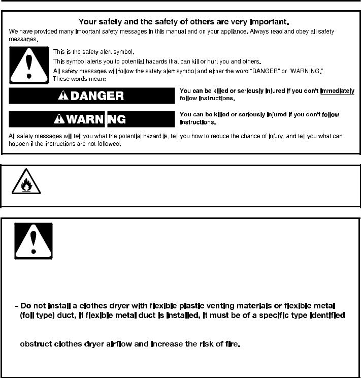
DRYER SAFETY
WARNING – “Risk of Fire” |
This is an additional safety alert symbol that alerts you to the risk of fire.
WARNING - “Risk of Fire”
-Clothes dryer installation and service must be performed by a Whirlpool authorized installer.
-Install the clothes dryer according to the manufacturer’s instructions and local codes.
by the appliance manufacturer as suitable for use with clothes dryers. Flexible venting materials are known to collapse, be easily crushed, and trap lint. These conditions will
-To reduce the risk of severe injury or death, follow all installation instructions.
-Save these instructions.
3
DRYER SAFETY
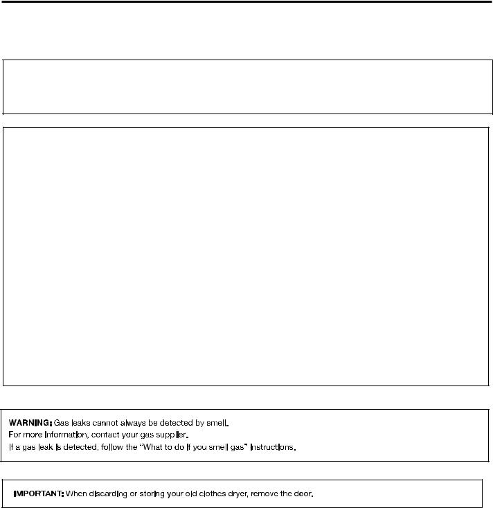
■■It is recommended that the owner post, in a prominent location, instructions for the customer’s use in the event the customer smells gas. This information should be obtained from your gas supplier.
■■Post the following warning in a prominent location.
FOR YOUR SAFETY
1.DO NOT USE OR STORE GAS OR OTHER FLAMMABLE MATERIALS IN THIS APPLIANCE OR NEAR THIS APPLIANCE.
2.DO NOT SPRAY AEROSOLS IN THE VICINITY OF THIS APPLIANCE WHILE IT IS IN OPERATION.
3.DO NOT MODIFY THIS APPLIANCE.
 WARNING:
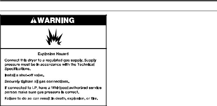
FIRE OR EXPLOSION HAZARD
Failure to follow safety warnings exactly could result in serious injury, death or property damage.
–Do not store or use gasoline or other flammable vapors and liquids in the vicinity of this or any other appliance.
–WHAT TO DO IF YOU SMELL GAS:
•Do not try to light any appliance.
•Do not touch any electrical switch; do not use any phone in your building.
•Clear the room, building, or area of all occupants.
•Immediately call your gas supplier from a neighbor's phone. Follow the gas supplier's instructions.
•If you cannot reach your gas supplier, call the fire department.
–Installation and service must be performed by a qualified installer, service agency, or the gas supplier.
4

DRYER SAFETY
IMPORTANT SAFETY INSTRUCTIONS
WARNING: To reduce the risk of fire, electric shock, or injury to persons when using the dryer, follow basic precautions,
including the following: |
|
|||
■■Read all instructions before using the dryer. |
|
|
■■The appliance is intended, but not limited, to be used in |
|
|
|
|
public areas. |
|
■■This dryer is intended only for drying clothes and textiles |
||||
|
||||
that have been washed in water. Do not use for any other |
■■Children of less than 3 years should be kept away unless |
|||
purpose. |
continuously supervised. |
|||
■■WARNING: If you smell gas, do not use the dryer or any |
■■The appliance must be disconnected from it's power |
|||
electrical equipment nearby. Warn other people to clear |
source during service and when replacing parts. |
|||
the area. Contact the dryer owner immediately. |
■■If drum rotation is blocked due to trapped textiles, |
|||
|
|
|
||
■■Do not place items exposed to cooking oils in your dryer. |
disconnect the dryer from the electrical supply before |
|||
Items contaminated with cooking oils may contribute |
gently removing the blockage. |
|||
to a chemical reaction that could cause a load to catch |
■■If the dryer is not heating, or appears to be defective or |
|||
fire. To reduce the risk of fire due to contaminated loads, |
||||
damaged, do not use it. Contact the owner. |
||||
the final part of a tumble dryer cycle occurs without heat |
||||
■■Do not install or store the dryer where it will be exposed |
||||
(cool down period). Avoid stopping a tumble dryer before |
||||
to the weather. |
||||
the end of the drying cycle unless all items are quickly |
||||
■■Do not tamper with controls. |
||||
removed and spread out so that the heat is dissipated. |
||||
■■If it is unavoidable that fabrics that contain vegetable or |
■■Clean dryer lint screen before or after each load. |
|||
cooking oil or that have been contaminated by hair care |
■■Do not use this dryer without the lint screen in place. |
|||
products be placed in a tumble dryer, they should first |
■■Do not repair or replace any part of the dryer or attempt |
|||
be washed in hot water with extra detergent – this will |
||||
any servicing unless specifically recommended in this |
||||
reduce, but not eliminate the hazard. |
||||
Installation Instructions that you understand and have the |
||||
■■Do not dry articles that have been previously cleaned |
||||
skills to carry out. |
||||
in, washed in, soaked in, or spotted with gas, |
■■Fabric softeners, or similar products, should be used as |
|||
dry-cleaning solvents, other flammable, or explosive |
||||
specified by the fabric softener instructions. |
||||
substances as they give off vapors that could ignite |
||||
■■Items such as foam rubber (latex foam), shower caps, |
||||
or explode. |
||||
■■Items that have been soiled with substances such as |
waterproof textiles, rubber-backed articles and clothes or |
|||
pillows fitted with foam rubber pads should not be dried |
||||
acetone, alcohol, gas, kerosene, spot removers, |
||||
in the tumble dryer. |
||||
turpentine, waxes, and wax removers should be washed |
||||
■■The final part of a tumble dryer cycle occurs without |
||||
in hot water with extra detergent before being dried in |
||||
the dryer. |
heat (cool-down cycle) to ensure that the articles are left |
|||
■■Do not dry unwashed items in the dryer. |
at a temperature that ensures that the items will not be |
|||
damaged. |
||||
■■Do not use this dryer if industrial chemicals have been |
||||
■■WARNING: Never stop a tumble dryer before the end of |
||||
used for cleaning. The possible presence of residual |
||||
the drying cycle unless all items are quickly removed and |
||||
quantities of aggressive or decomposed chemicals in the |
||||
spread out so that the heat is dissipated. (Avoids risk of |
||||
load may produce damage to the dryer and harmful fumes. |
||||
spontaneous combustion). |
||||
■■Do not allow children to play on, in, or with the dryer. |
||||
■■In case of electrical supply failure, remove the load |
||||
Close supervision of children is necessary when the dryer |
||||
quickly and spread it out to avoid risk of spontaneous |
||||
is used near children. |
||||
combustion. |
||||
■■This dryer is not intended for use by persons (including |
||||
■■Keep area around the exhaust opening and adjacent |
||||
children) with reduced physical, sensory, or mental |
||||
surrounding areas free from the accumulation of lint, dust, |
||||
capabilities, or lack of experience or knowledge, |
||||
and dirt. |
||||
unless they have been given supervision or instruction |
||||
■■The fresh air ventilation openings into the room and into |
||||
concerning use of the dryer by a person responsible for |
||||
their safety. |
the dryer must not be blocked or sealed. |
|||
■■Before the dryer is removed from service or discarded, |
■■Emergency stop control: After installation, access to |
|||
remove the door to the dryer compartment. |
mains plug (gas dryer) or mains supply (electric dryer) |
|||
■■Do not reach into the dryer if the drum is moving. |
via a double-pole switch must be maintained at all times |
|||
in order to ensure immediate deactivation of the dryer in |
||||
■■Do not open door while dryer is in operation. It will stop. |
||||
case of emergency. |
||||
■■When loading or re-loading the dryer, avoid touching hot |
■■The interior of the dryer and dryer exhaust vent should |
|||
metal parts of the drum (burn risk). |
be cleaned periodically by Whirlpool authorized service |
|||
■■Remove all objects from pockets such as lighters and |
personnel. |
|||
matches. |
■■See “Electrical Requirements” section for earthing |
|||
■■Cleaning and user maintenance shall not be made by |
instructions. |
|||
children without supervision. |
■■Adequate ventilation has to be provided to avoid the |
|||
■■WARNING: The appliance must not be supplied through |
back-flow of gases into the room from appliances burning |
|||
an external switching device, such as a timer, or connected |
fuels, including open fires. |
|||
to a circuit that is regularly switched on and off by a utility. |
|
|||
■■The dryer must not be installed behind a lockable door, a sliding door, or a door with a hinge on the opposite side to that of the dryer in such a way that full opening of the dryer
door is restricted.
SAVE THESE INSTRUCTIONS
5

MAINTENANCE INSTRUCTIONS
■■ Clean lint screen before and after each cycle. ■■ Removing accumulated lint:
From inside the dryer cabinet:
Lint should be removed every 2 years or more often, depending on dryer usage. Cleaning should be done by a Whirlpool authorized person.
From the exhaust vent:
Lint should be removed every 2 years, or more often, depending on dryer usage.
■■ Keep area around dryer clear and free from combustible materials, gas, and other flammable vapors and liquids.
■■ Keep dryer area clear and free from items that would obstruct the flow of combustion and ventilation air.
If dryer does not operate, check the following:
■■Electrical supply is connected.
■■Circuit breaker is not tripped or house fuse is not blown.
■■Door is closed. Listen closely to hear the door switch activate.
■■Controls are set in a running or “on” position.
■■For gas dryers, check that gas supply shut-off valves are set in open position.
WARNING: Improper connection of the equipment-earthing conductor can result in a risk of electric shock. It is your responsibility to check with a qualified electrician or service representative if you are in doubt as to whether the dryer is properly earthed and meets all local codes and ordinances. Do not modify the plug provided with the dryer: If it will not fit the outlet, have a proper outlet installed by a qualified electrician.
IF YOU NEED ASSISTANCE
If you need help, contact the dealer from whom you purchased the appliance, or a Maytag designated service company. When calling, please know the purchase date and the complete model and serial number of your appliance. This information will help us to better respond to your request.
IF YOU NEED SERVICE:
Contact your authorized Maytag Commercial Laundry distributor. To locate your authorized Maytag Commercial Laundry distributor, visit www.maytagcommerciallaundry.com.
For written correspondence:
Maytag Commercial Laundry Service Department
2000 N M 63
Benton Harbor, Michigan 49022-2632 USA
6
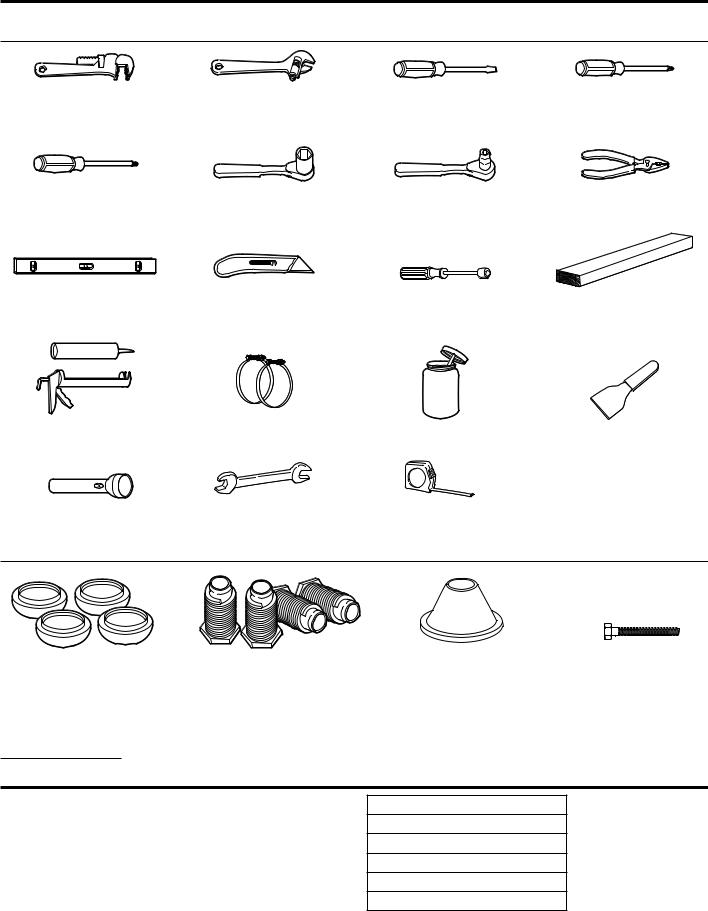
TOOLS & PARTS
Tools Needed:
203 mm (8") |
203 mm (8") or 254 mm (10") |
Flat-Blade Screwdriver |
Phillips Screwdriver |
or 254 mm (10") |
Adjustable Wrench |
|
|
Pipe Wrench |
(that opens to 25 mm (1")) |
|
|
Torx T-20† Security |
25 mm (1") Hex-Head |
8 mm (5⁄16") Socket Wrench |
Pliers (that open to |
Screwdriver or Bit |
Socket Wrench |
|
39 mm [19/16"]) |
Level |
Utility Knife |
6 mm (1/4") Nut Driver |
686 mm (27") |
|
|
|
Wood Block |
Caulk Gun and Caulk |
Vent Clamps |
Pipe-Joint Compound |
Putty Knife |
(for installing new exhaust vent) |
|
Suitable for Gas Type |
|
Flashlight (optional) |
25 mm (1") |
Ruler or Measuring Tape |
|
Open-End Wrenches |
|
Parts Supplied:
Foot Boots (4) |
Leveling Legs (4) |
NOTE: The circuit diagram for this dryer is located inside the lower front panel, within the Tech Sheets.
Technical Specifications:
220 – 240 V, 50 Hz. AC
4575W
Total mass: 68 kg max.
Security Cone |
5/16" Hex Head – 18 x 21⁄2" |
|
Security Bolt |
SPECIFICATIONS
These units are sold in multiple regions with different requirements for measuring capacity. Below are a few of the valid forms of measure posted on this product:
Dry Linen Capacity: A weight measure that reflects a minimum threshold for dry volume capacity that is needed for import tariff purposes.
IEC Capacity: The capacity measure that represents the maximum capacity of dry linens and textiles which the manufacturer declares can be treated in a specific cycle.
†TORX and T20 are trademarks of Acument Intellectual Properties, LLC.
Dry Linen Capacity
10.5 kg (23 lb)
IEC Capacity
9.0 kg (20 lb)
Sound Level
LpA: 58 dB(A) (Kpa+/-10 dB(A))
7
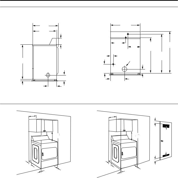
DIMENSIONS/CLEARANCES
Dimensions
Side View |
Back View |
|
743 mm |
|
|
686 mm |
|
|
|
|
|
(291/4") |
|
|
|
|
|
||
|
660 mm |
|
|
|
(27") |
|
|
|
|
|
|
|
|
|
|
|
|
|
(26") |
|
|
Electric |
|
|
|
|
|
|
|
|
|
|
|
||
|
210 mm |
|
343 mm |
|
|
|
|
|
|
(81/4") |
|
(131/2") |
273 mm |
914 mm |
1042 mm |
||
|
|
|
|
|
(103/4") |
(36") |
|
(41") |
|
|
|
|
|
|
(electric models) |
|
|
|
|
|
38 mm |
|
|
|
953 mm |
|
889 mm |
|
|
(11/2") |
|
102 mm |
|
(371/2") |
|
|
|
|
|
(4" dia) |
(gas models) |
|||
(35") |
|
|
|
|
|
|
|
|
|
83 mm |
140 mm |
Gas |
|
|
|
|
|
|
(3 |
1 |
|
|
|
|
|
|
|
/4") |
(51/2") |
|
|
|
|
|
|
|
|
|
|
343 mm |
|
83 mm |
|
|
|
|
|
|
(131/2") |
|
|
|
|
|
191 mm |
|
|
|
|
(31/4") |
|
|
25 mm |
(71/2") |
|
|
|
|
|
|
|
(1") |
|
|
|
|
|
|
|
|
Clearances
Front View, Recessed Opening |
|
Side View, Recessed In Closet |
|
|||
356 mm |
|
356 mm |
|
|
|
|
(14" max) |
|
|
|
|
|
|
|
(14" max) |
|
|
|
|
|
|
|
|
|
|
|
|
|
|
|
|
|
76 mm |
|
|
|
|
|
|
(3"/3") 310 cm2 |
|
|
381 mm |
|
|
|
381 mm |
(48"2/48"2) |
|
(15") |
|
|
|
(15") |
|
|
|
|
|
|
|
155 cm2 |
|
|
|
|
|
76 mm |
(24"2/24"2) |
|
|
|
|
|
(3"/3") |
|
0 mm |
|
127 mm |
|
|
|
|
(0") |
|
|
25 mm |
|
||
0 mm |
(5") |
|
|
|
||
|
|
|
|
(1") |
|
|
0 mm |
(0") |
|
|
|
|
|
|
|
25 mm |
Closet Door to |
|
||
(0") |
|
|
|
Front of Dryer |
|
|
|
|
|
(1") |
|
||
|
|
|
|
|
|
|
8
DRYER INSTALLATION REQUIREMENTS
(Australia and New Zealand – for full details of installation requirements refer to AS/NZS 5601.1)
Location Requirements
Your dryer can be installed in a basement, laundry room, or recessed area.
This dryer is not intended for installation in a mobile home.
Companion appliance location requirements should also be considered.
IMPORTANT: Do not install or store the dryer where it will be exposed to the weather. Proper installation is your responsibility.
You will need:
■■An grounded electrical outlet located within 1.8 m (6 ft.) of where the power cord is attached to the back of the dryer. See “Electrical Requirements.”
■■A level floor with a maximum slope of 25 mm (1") under entire dryer. Installing the dryer on soft floor surfaces, such as carpets or surfaces with foam backing, is not recommended.
Dryer installation clearances
■■The location must be large enough to allow the dryer door to be fully opened.
■■Additional spacing should be considered for ease of installation and servicing. The door opens more than 180°.
■■Additional clearances might be required for wall, door, and floor moldings.
■■Additional spacing of 25 mm (1") on all sides of the dryer is recommended to reduce noise transfer.
When installing a dryer:
IMPORTANT: Observe all governing codes and ordinances.
■■Check code requirements: Some codes limit or do not permit installation of clothes dryers in garages, closets,
or sleeping quarters. Contact your local building inspector.
NOTE: For installation in Australia and New Zealand, install dryer in accordance with AS/NZS 5601.1 and local governance codes.
Recessed Area and Closet Installation Instructions
This dryer may be installed in a recessed area or closet. For recessed area and closet installations, minimum clearances can be found on the warning label on the rear of the dryer or in “Dimensions/Clearances.”
The installation spacing is in millimeters and is the minimum allowable. Additional spacing should be considered for ease of installation, servicing, and compliance with local codes and ordinances.
If closet door is installed, the minimum unobstructed air opening in the top and bottom is required. The unobstructed opening needs to be 1 square inch per 1,000 Btu (252 kcal) of gas burner output. Output on North American gas dryers is typically 22,000 Btu; however, Canadian dryers may have lower output. Louvered doors with equivalent air openings are acceptable.
The dryer must be exhausted outdoors.
No other fuel-burning appliance may be installed in the same closet as the dryer.
NOTE: For installation in Australia and New Zealand, refer to AS/NZS 5601.1 for ventilation requirements.
|
|
|
|
|
|
|
|
|
|
|
|
|
|
|
|
|
|
|
|
|
|
|
|
|
|
|
|
|
|
|
|
|
|
|
|
|
|||
Front |
|
Closet |
|
||||||
View |
|
|
Door |
|
|
|
|||
|
|
|
|
|
|
|
|
|
|
|
|
|
|
|
|
|
|
|
|
|
|
|
|
|
|
|
|
|
|
|
|
|
|
|
|
|
|
|
|
|
|
|
|
|
|
|
|
|
|
|
|
|
|
|
|
|
|
|
|
|
|
|
|
|
|
|
|
|
|
■■Gas Dryers only: Make sure that lower edges of the cabinet, plus the back and bottom sides of the dryer, are free of obstructions to permit adequate clearance of air openings for combustion air. See “Recessed Area and Closet Installation Instructions” below for minimum spacing requirements.
9
INSTALLING LEVELING LEGS AND COIN BOX
The console houses the electronic control board. The board is factory set for a dry time of 30 minutes. Consult the tech sheet found inside the dryer toe panel to reset dry time and for other options.
The card reading mechanism is not included, but is available from your usual industry sources.
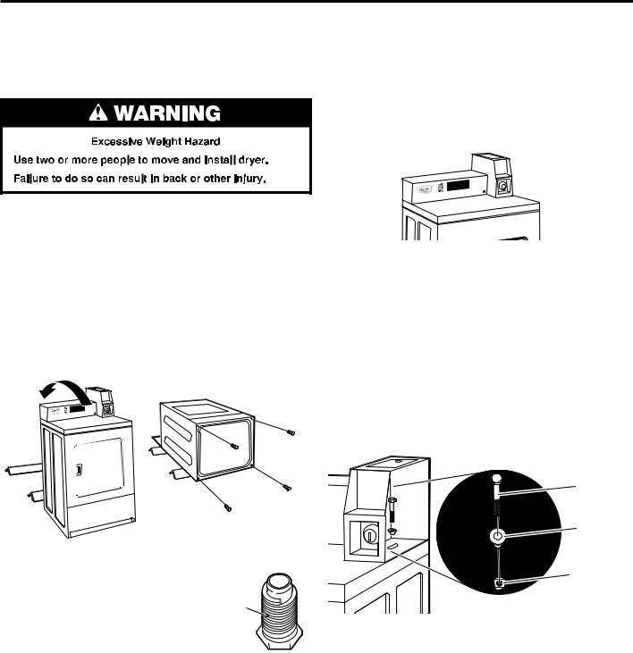
1. Prepare dryer for leveling legs
NOTE: Slide dryer onto cardboard or hardboard before moving to avoid damaging floor covering.
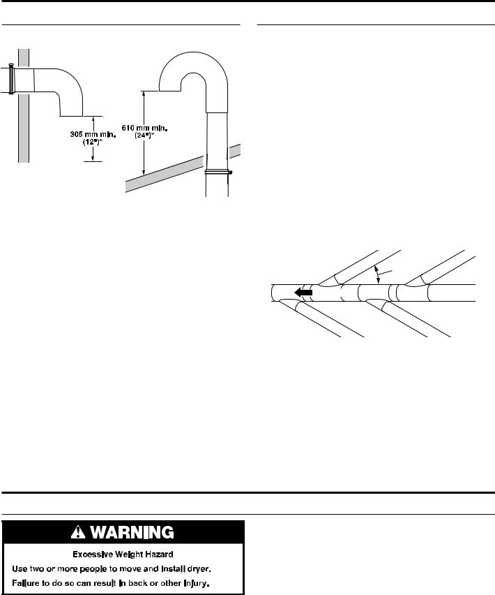
Using two or more people, move dryer to desired installation location.
Take tape off front corners of dryer. Open dryer and remove the literature and parts packages. Wipe drum interior with a damp cloth to remove any dust.
Take two cardboard corners from the dryer carton and place them on the floor in back of the dryer. Firmly grasp the body of the dryer and gently lay it on its back on the cardboard corners. Disconnect power before making electrical connections.
The meter case houses the factory-installed accumulator timer with actuating arm or service switch.
The service door lock and key and coin box lock and key may not be included but are available from the usual industry sources.
1. Install coin box
Remove the service door of the meter case by lifting it up at the back. Install the money-accepting device. (Refer to manufacturer’s instructions for proper installation.)
Replace the meter case service door. Put the coin vault with lock and key in the meter case opening.
Remove cardboard or hardboard from under dryer. Adjust the legs of the dryer up or down until the dryer is level.
2. Install added security device
Check that power is not supplied to the dryer. Open and remove the service door.
Insert the narrow part of the security cone into the oblong hole in the bottom rear of the meter case assembly.
Pass the security bolt through this cone and thread it by hand into the cage nut below the oblong hole.
Tighten the security bolt by hand a few turns before using a wrench to tighten until snug.
(appearance may vary)
2. Screw in leveling legs
Examine leveling legs and find diamond marking. Screw legs into leg holes by hand. Use an adjustable wrench or
25 mm (1") hex-head socket wrench to finish turning legs until diamond marking is no longer visible. Then fit
a covered foot boot over each leg foot.
Diamond
Marking
Foot 

To protect the floor, use a large piece of cardboard from the dryer carton. Stand dryer up on the cardboard. Slide the dryer until it is close to its final location. Leave enough room for electrical connection and to connect the exhaust vent.
A longer leveling foot is available if needed on extremely sloped floors, Part Number 279810.
Security
security
Bolt
bolt
Security
security
Cone
cone
Cage
cage nut
Nut
NOTE: Installing the security bolt provides added security, but will add to the service time when the top needs to be removed for servicing the dryer.
10
LEVELING
Leveling your dryer properly reduces excess noise and vibration.
1.Remove cardboard from beneath dryer. Place a level on top edges of dryer, checking each side and front. If not level, tip dryer and adjust legs up or down as shown in Step 3, repeating as necessary.
|
|
|
|
|
|
|
|
|
|
|
|
|
|
|
|
|
|
|
|
|
|
|
|
|
|
|
|
|
|
|
|
|
|
|
|
|
|
|
|
|
|
|
|
|
|
|
|
|
|
|
|
|
|
|
|
|
|
|
|
|
|
|
|
|
|
|
|
|
|
|
|
|
|
|
|
|
|
|
|
|
|
|
|
|
|
|
|
|
|
|
|
|
|
|
|
|
|
|
|
|
|
|
|
|
|
|
|
|
|
|
|
|
|
|
|
|
|
|
|
|
|
|
|
|
|
|
|
|
|
|
|
|
|
|
|
|
|
|
|
|
|
|
|
|
|
|
|
|
|
|
|
|
|
|
|
|
|
|
|
|
|
|
|
|
|
|
|
|
|
|
|
|
|
|
|
|
|
|
|
|
|
|
|
|
|
|
|
|
|
|
|
|
|
|
|
|
|
|
|
|
|
|
|
|
|
|
|
|
|
|
|
|
|
|
|
|
|
|
|
|
|
|
|
|
|
|
|
|
|
|
Not Level |
|
|
|
LEVEL |
|
|
|
|
|
Not Level |
|
||||||||||
2.Grip dryer from top and rock back and forth, making sure all four legs are firmly on floor. Repeat, rocking dryer from side to side. If dryer rocks, go to Step 3 and adjust leveling legs.
3.If dryer is not level, use a 25 mm or 1" open-end or adjustable wrench to turn the leveling leg counterclockwise to lower the dryer or clockwise to raise the dryer. Recheck levelness of dryer and that all four legs are firmly in contact with the floor. Repeat as needed.
HELPFUL TIP: You may want to prop up front of dryer about 102 mm (4") with a wood block or similar object that will support weight of dryer.
11
ELECTRIC DRYER INSTALLATION REQUIREMENTS
Electrical Requirements
IMPORTANT: Observe all governing codes and ordinances.
This dryer is supplied without an electric cord and plug. It must be connected by a Whirlpool authorized service person to a single-phase electricity supply at the voltage shown
on the dataplate, using a suitable fixed wiring installation in accordance with local and national wiring regulations.
■■A 3-wire circular cord of minimum conductor size 2.5 mm2 cross-section area should be used.
■■A 25 A (minimum) supply fuse should be used, and a switch with a clear OFF marking having a contact separation in both poles that provides full disconnection under overvoltage category III conditions must be incorporated into the fixed wiring in accordance with local wiring regulations by
a Whirlpool authorized service person. The dryer should be positioned so that the disconnection switch is clearly visible and easily accessible to the user. This disconnection switch also provides the function of an emergency stop control for the user.
■■A cord clamp bush is provided on the dryer, and should be tightened on completion of wiring. The electrical mains terminals are located behind the small rear access panel (terminal block cover), and connections should be made in accordance with the terminal markings. Remember to replace the terminal access panel (terminal block cover).
NOTE: In accordance with the European EMC Directive (2004/108/EC), the maximum electrical supply system impedance to which the electric dryer should be connected is declared to be 0.054 Ohm + j0.034 Ohm.
NOTE: Electrical safety standards: The manufacturer has chosen compliance with IEC/EN.60335 standards as the most appropriate for this product.


 .
.
If codes permit and an additional ground bond wire is used, it is recommended that a qualified electrician determine that the ground bond path is adequate.
Recommended Earthing Method
It is your responsibility to contact a qualified electrical installer to ensure that the electrical installation is adequate and in conformance with all local codes and ordinances.
12
GAS DRYER INSTALLATION REQUIREMENTS
Electrical Requirements
IMPORTANT: Observe all governing codes and ordinances.
You will need a grounded electrical outlet located within 610 mm (2 feet) of either side of the dryer.
This dryer is supplied/fitted with an electrical supply cord and plug. It should be connected to electrical supply socket at the voltage shown on the rating plate. The minimum supply fuse capacity should be 10 A. The dryer must be positioned so that the plug is clearly visible and accessible. This plug also provides the function of an emergency stop control for the user. If the fitted plug is not used, the electrical connection must be carried out by a competent electrician in accordance with local or national codes.
If the supply cord is damaged, it must be replaced with a specially terminated cord by an authorized service agent or a similarly competent person in order to avoid a hazard.
Do not use an adapter.
Do not use an extension cord.
NOTE: In accordance with the European EMC Directive (2004/108/EC), the maximum electricity supply system impedance to which the gas dryer should be connected is declared to be 0.054 Ohm + j0.034 Ohm.
NOTE: Electrical safety standards: The manufacturer has chosen compliance with IEC/EN.60335 standards as the most appropriate for this product.
EARTHING INSTRUCTIONS
SAVE THESE INSTRUCTIONS
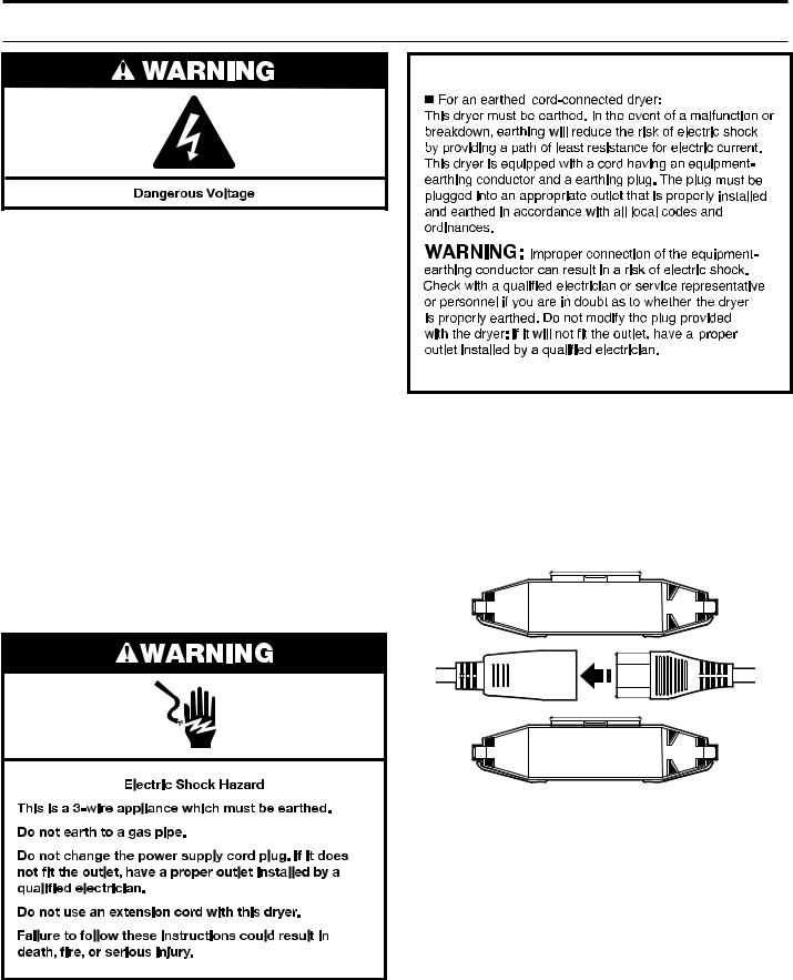
Using the universal cord included with this dryer:
The gas dryer is equipped with a universal cord with interchangeable plugs.
1.To use the universal cord, select the plug end that fits your electrical outlet, and plug it into the adapter on the supply cord.
2.Secure the plug end in place on the cord by aligning the 2 cover halves over the cord adapter and clipping them together.
If codes permit and an additional ground bond wire is used, it is recommended that a qualified electrician determine that the ground bond path is adequate.
13
GAS DRYER INSTALLATION REQUIREMENTS
Gas Supply
IMPORTANT: Observe all governing codes and ordinances. In Australia and New Zealand, refer to AS/NZS 5601.1 – Gas Installations.
Gas Supply
Before installation, check that the local gas distribution conditions, nature of gas and pressure, and the adjustment of the appliance are compatible. Burner information will be found on the model/serial rating plate in the door recess of the dryer. If this information does not agree with the type of gas available, see your dealer.
Natural Gas:
This dryer is factory adjusted for use with NATURAL GAS (G20), and no further adjustment should be required at installation.
L.P. Gas:
This dryer is also certified for use with L.P. (propane or butane) gases with appropriate conversion. No attempt shall be made to convert the appliance from the gas specified on the model/ serial rating plate for use with a different gas without consulting the serving gas supplier.
Conversion must be done by a Whirlpool authorized service technician. Gas conversion kit (European Country), part number W10233219, is available for purchase from your dealer. Gas conversion kit (Australia), part number W10315369, is available for purchase from your dealer. Full instructions are supplied with the kit.
Natural Gas (France/Belgium):
This dryer is also certified for France/Belgium for use with G20/ G25 gases (20 mbar/25 mbar) with appropriate conversion. No attempt should be made to convert this appliance from the gas specified on the gas rating label for use with a different gas without consulting the serving gas supplier. Gas conversion must be done by a Whirlpool authorized gas service technician. Conversion kit, part number (W10181947) is available for purchase from your dealer. Full instructions are supplied with the kit.
Supply line requirements:
Provide a rigid gas supply line to the dryer location. It should be minimum 12.5 mm (1/2") ID. When acceptable to the gas supplier and local codes, 10 mm (3/8") ID rigid supply line may be used for lengths under 6.1 m (20'). Pipe-joint compounds resistant to the action of L.P. gas must be used.
NOTE: For installation in Australia and New Zealand, refer to AS/NZS 5601 for pipe sizing details. All piping is to be in accordance with AS/NZS 5601.1 – Gas Installations.
Gas connection to the dryer itself should be made by means of a flexible gas hose suitable for the appliance and gas category in accordance with national installation regulations. If in doubt, contact the gas supplier. It should be minimum
10 mm (3/8") ID.
A means of restraint should be used between the dryer and the wall to avoid straining of the rigid gas supply when the dryer
is moved. An appropriate length of chain and a wall hook is recommended.
The dryer gas inlet connection is a 3/8" NPT thread. An adapter is supplied for conversion to standard ISO.228-1 thread
(3/8" BSP).
Check for leaks by using an approved noncorrosive leakdetection solution. Bubbles will show a leak. Correct any leak found. A pressure measurement tapping is provided on the gas valve within the dryer, accessible after removal of the lower front panel.
The dryer must be disconnected from the gas supply piping system during any pressure testing of that system.
14
DRYER VENTING REQUIREMENTS
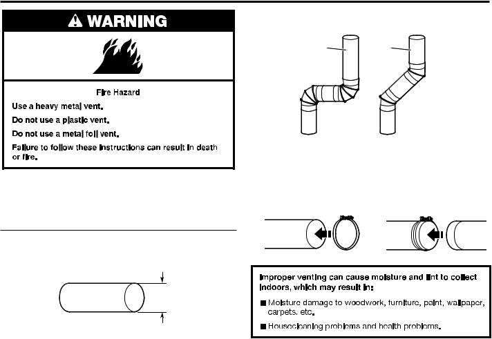
WARNING: To reduce the risk of fire, this dryer MUST BE EXHAUSTED OUTDOORS.
IMPORTANT: Observe all governing codes and ordinances. In Australia and New Zealand, refer to AS/NZS 5601.1 – Gas Installations.
Dryer exhaust must not be connected into any gas vent, chimney, wall, ceiling, attic, crawlspace, or a concealed space of a building. Only rigid or flexible metal vent shall be used for exhausting.
102 mm (4")
102 mm (4") Heavy, Metal Exhaust Vent
■■Only a 102 mm (4") heavy, metal exhaust vent and clamps may be used.
■■Do not use plastic or metal foil vent.
Rigid metal vent:
■■Recommended for best drying performance and to avoid crushing and kinking.
Flexible metal vent: (Acceptable only if accessible to clean) ■■Must be fully extended and supported in final dryer location.
■■Remove excess to avoid sagging and kinking that may result in reduced airflow and poor performance.
■■Do not install in enclosed walls, ceilings, or floors. ■■The total length should not exceed 2.4 m (73⁄4 ft.).
NOTE: If using an existing vent system, clean lint from entire length of the system and make sure exhaust hood is not plugged with lint. Replace plastic or metal foil vents with rigid metal or flexible metal vents. Review “Vent System Chart” and if necessary, modify existing vent system to achieve best drying performance.
Elbows:
■■45° elbows provide better airflow than 90° elbows.
Good |
Better |
Clamps:
■■Use clamps to seal all joints.
■■Exhaust vent must not be connected or secured with screws or other fastening devices that extend into interior of duct and catch lint. Do not use duct tape.
15
DRYER VENTING REQUIREMENTS
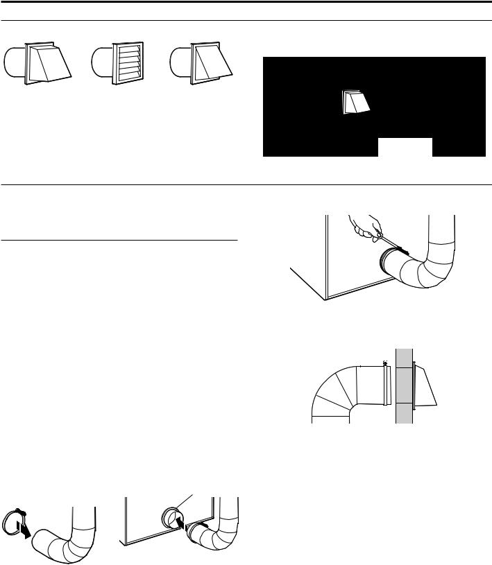
Vent Hoods
102 mm (4") Diameter Exhaust Hoods |
Exhaust hood must be at least 305 mm (12") from the ground |
|
or any object that may be in the path of the exhaust (such as |
|
flowers, rocks, bushes, or snow). |
Box Hood |
Louvered Hood |
Angled Hood |
|
30512" mmin. min. |
|
(305 mm)(12") |
Vent System Length |
|
Maximum Vent Length/Vent Connection |
|
Maximum length of vent system depends upon the type of vent |
3. Tighten hose clamp with Phillips screwdriver. |
used, number of elbows, and type of exhaust hood. |
|
Vent System Chart (Rigid Metal Vent) |
|
|
Box and |
|
No. of 90˚ Turns |
Louvered Hood |
Angled Hood |
|
|
|
0 |
39.6 m (130 ft.) |
39.3 m (129 ft.) |
1 |
38.1 m (125 ft.) |
36.3 m (119 ft.) |
2 |
35.1 m (115 ft) |
33.2 m (109 ft.) |
3 |
32.3 m (106 ft.) |
30.5 m (100 ft.) |
4 |
29.9 m (98 ft.) |
28.0 m (92 ft.) |
For vent systems not covered by the vent specification chart, see your parts distributor.
Provision must be made for enough air for combustion and ventilation. (Check governing codes and ordinances.) See “Recessed Area and Closet Installation Instructions” in the “Location Requirements” section.
A 102 mm (4") outlet hood is preferred. However, a 64 mm (21⁄2") outlet exhaust hood may be used. A 64 mm (21⁄2") outlet creates greater back pressure than other hood types. For permanent installation, a stationary vent system is required.
Connect Vent
1.If connecting to existing vent, make sure the vent is clean.
2.Using a 102 mm (4") clamp, connect vent to exhaust outlet
in dryer.
4.Make sure the vent is secured to exhaust hood with a 102 mm (4") clamp.
5.Move dryer into final position. Do not crush or kink vent. Make sure dryer is level.
NOTE: Testing for proper ventilation should be done with a Manometer. Minimum: 0.01" (0.2 mm). Maximum: 0.6" (16 mm).
NOTE: Do not remove vent collar.
16
DRYER VENTING REQUIREMENTS
If an Exhaust Hood Cannot be Used
The outside end of main vent should have a sweep elbow directed downward.
*Minimum clearance above any accumulation of snow, ice, or debris such as leaves
If main vent travels vertically through the roof, rather than through wall, install a 180° sweep elbow on end of vent at least 610 mm (2 ft.) above surface of roof.
The opening in wall or roof shall have a diameter 13 mm (1⁄2") larger than vent diameter. Vent should be centered in opening.
Do not install screening over end of vent for best performance.
Multiple Dryer Venting
A main vent can be used for venting a group of dryers. The main vent should be sized to remove 5663 l/min. (200 CFM) of air per dryer. Large-capacity lint screens of proper design may be used in main vent if checked and cleaned frequently. The room where the dryers are located should have make-up air equal to or greater than CFM of all the dryers in the room.
Back-draft dampers are available from your distributor and should be installed in the vent of each dryer to keep exhausted air from returning into dryers and to keep exhaust in balance within main vent. Unobstructed return air openings are required.
Although usually each single-load dryer should have an unobstructed outdoor air opening of 154 cm2 (24 in.2) (based on 6.5 cm2 [1 in.2] per 252 kcal [1,000 Btu]), common make-up air openings are also acceptable. Set up common openings so the make-up air is distributed equally to all of the dryers. Keep in mind that the coverage area must be increased by 33% to account for the use of registers or louvers over the openings. Also, make-up air openings should not be installed near the location where exhaust vents exit the building.
Each vent should enter the main vent at an angle pointing in the direction of the airflow. Vents entering from the opposite side should be staggered to reduce the exhausted air from interfering with the other vents.
 AirFlow
The maximum angle of each vent entering the main vent should be no more than 30°.
Keep air openings free of dry cleaning fluid fumes. Fumes create acids which, when drawn through the dryer heating units, can damage dryers and items being dried.
A clean-out cover should be located on the main vent for periodic cleaning of the vent system.
NOTE: For more dryer venting information, please refer to Whirlpool document W10100920.
GAS SUPPLY CONNECTION (on some models)
Make Gas Connection
1.Connect gas supply to dryer. If the flexible gas hose has 10 mm (3/8") BSP thread, use the supplied conversion thread adapter. Use pipe-joint compound resistant to the action of L.P. gas for gas connections.
If necessary for service, open the toe panel. Use a putty knife to press on the 2 toe panel locks located at the top of the toe panel. Pull downward on the toe panel to open. Toe panel is hinged at the bottom.
2.Open the shut-off valve in the gas supply line and make sure the dryer has its own gas supply opened.
3.Test all connections by brushing on an approved noncorrosive leak-detection solution. Bubbles will show a leak. Correct any leaks found.
17
TECHNICAL SPECIFICATIONS – GAS DRYER
220–240 V~50 Hz 1 ph 3 A max. IP24 Clothes capacity: 9.0 kg max. Sound pressure level, Lpa: 58 dBA (uncertainty, Kpa: +/-10 dBA) Total mass: 68 kg max.
Factory set for NATURAL GAS: Injector size: 2.2 mm Heat input gross: 5.9 kW
European Country: |
CH, CZ, CY, ES, GB, GR, |
BG, CY, CZ, DK, EE, FI, GR, |
|
IE, IT, LT, PT, SI, SK, TR |
HR, IT, LT, NO, RO, SE, SI, SK |
||
|
|||
|
|
|
|
European Gas Category: |
II2H3+ |
II2H3B/P |
|
Gas Flow Rate: |
0.562703 m3/hr |
0.562703 m3/hr |
|
Supply Pressure (G20): |
20 mbar |
20 mbar |
|
|
|
|
|
Factory Adjusted Pressure: |
7.4 mbar |
7.4 mbar |
|
|
|
|
|
With L.P. Gas Conversion Kit: Injector size: 1.25 mm Heat input gross: 6.4 kW |
|
||
|
|
|
|
European Country: |
CH, CZ, CY, ES, GB, GR, |
BG, CY, CZ, DK, EE, FI, GR, |
|
IE, IT, LT, PT, SI, SK, TR |
HR, IT, LT, NO, RO, SE, SI, SK |
||
|
|||
|
|
|
|
European Gas Category: |
II2H3+ |
II2H3B/P |
|
Butane Supply Pressure (G30): |
28-30 mbar |
30 mbar |
|
|
|
|
|
Adjusted Pressure: |
N/A |
N/A |
|
|
|
|
|
L.P. Supply Pressure (G31): |
37 mbar |
30 mbar |
|
|
|
|
|
Adjusted Pressure: |
N/A |
N/A |
|
|
|
|
|
With France/Belgium NATURAL GAS conversion kit: Injector size 1.65 mm Heat input gross: 5.9 kW
European Country: |
FR, BE |
|
|
|
|
European Gas Category: |
I2E+ |
|
Supply Pressure (G20): |
20 mbar |
|
|
|
|
Supply Pressure (G25): |
25 mbar |
|
|
|
|
Adjusted Pressure: |
N/A |
|
|
|
|
Factory set for NATURAL GAS: Injector size: 2.2 mm Heat input gross: 5.9 kW |
||
|
|
|
Country: |
AT, BG, CH, CZ, DK, EE, ES, FI, GB, GR, HR, |
|
IE, IS, IT, LT, LV, NO, PT, RO, SE, SI, SK, TR |
||
|
||
European Gas Category: |
I2H |
|
Gas Flow Rate: |
0.562703 m3/hr |
|
Supply Pressure (G20): |
20 mbar |
|
|
|
|
Factory Adjusted Pressure (G20): |
7.4 mbar |
|
|
|
|
Factory set for NATURAL GAS: Injector size: 2.2 mm Heat input gross: 5.9 kW |
||
|
|
|
Country: |
LU, RO |
|
|
|
|
European Gas Category: |
II2E3B/P |
|
Gas Flow Rate: |
0.562703 m3/hr |
|
Supply Pressure (G20): |
20 mbar |
|
|
|
|
Factory Adjusted Pressure (G20): |
7.4 mbar |
|
|
|
|
With L.P. Gas Conversion Kit: Injector size: 1.25 mm Heat input gross: 6.4 kW |
||
|
|
|
Country: |
LU, RO |
|
|
|
|
European Gas Category: |
II2E3B/P |
|
Butane Supply Pressure (G30): |
30 mbar |
|
|
|
|
Adjusted Pressure: |
N/A |
|
|
|
|
L.P. Supply Pressure (G31): |
30 mbar |
|
|
|
|
Adjusted Pressure: |
N/A |
|
|
|
|
18

TECHNICAL SPECIFICATIONS – GAS DRYER
Factory set for NATURAL GAS: Injector size: 2.2 mm Heat input gross: 5.9 kW
Country: |
DE, LU, PL, RO |
|
|
|
|
|
|
European Gas Category: |
I2E |
|
|
Gas Flow Rate: |
0.562703 m3/hr |
|
|
Supply Pressure (G20): |
20 mbar |
|
|
|
|
|
|
Factory Adjusted Pressure (G20): |
7.4 mbar |
|
|
|
|
|
|
Factory set for Australia/New Zealand NATURAL GAS: Injector size: 2.2 mm Heat input gross: 5.9 kW |
|||
|
|
|
|
Country: |
AU, NZ |
|
|
|
|
|
|
Supply Pressure (G20): |
minimum 1.13 kPa |
|
|
|
|
|
|
Adjusted Pressure (Test Point Pressure): |
0.74 kPa |
|
|
|
|
|
|
Nominal Hourly Gas Consumption: |
21.1 MJ/h |
|
|
|
|
|
|
With Australia L.P. Gas Conversion Kit: Injector Size: 1.40 mm Heat input gross: 6.54 kW |
|
||
|
|
|
|
Country: |
AU, NZ |
|
|
|
|
|
|
L.P. Supply Pressure: |
2.75 kPa |
|
|
|
|
|
|
Adjusted Pressure: |
2.75 kPa |
|
|
|
|
|
|
Nominal Hourly Gas Consumption: |
23 MJ/h |
|
|
|
|
|
|
Factory set for NATURAL GAS: Injector size: 2.2 mm Heat input gross: 5.0 kW |
|
||
|
|
|
|
Country: |
NL |
|
|
|
|
|
|
European Gas Category: |
I2L |
|
II2L3B/P |
Gas Flow Rate: |
0.562703 m3/hr |
|
0.562703 m3/hr |
Gas Flow Rate: |
25 mbar |
|
25 mbar |
|
|
|
|
Factory Adjusted Pressure (G25) : |
7.4 mbar |
|
7.4 mbar |
|
|
|
|
With L.P. Gas Conversion Kit: Injector size: 1.25 mm Heal input gross: 6.4 kW |
|
||
|
|
|
|
Country: |
MT, PL |
|
NL |
|
|
|
|
European Gas Category |
I3B/P |
|
II2L3B/P |
Butane Supply Pressure (G30) |
30 mbar |
|
|
|
|
|
|
Adjusted Pressure: |
N/A |
|
|
|
|
|
|
L.P. Supply Pressure: |
30 mbar |
|
|
|
|
|
|
Adjusted Pressure: |
N/A |
|
|
|
|
|
|
NOTE: Conversion kit: From Natural Gas to L.P. Gas - Europe: Whirlpool Part No. W10233219. Conversion kit: From Natural Gas to L.P. Gas - Australia: Whirlpool Part No. W10315369. Conversion kit: From Natural Gas to Natural Gas - France/Belgium: Whirlpool Part No. W10181947.
Manufacturer: Whirlpool Corporation, Benton Harbor, Michigan 49022, U.S.A.
Manufacturing Site: Whirlpool Corporation, 1300 Marion-Agosta Rd., Marion, OH, 43302, U.S.A. EU Representatives: Whirlpool EMEA S.p.A., Via Carlo Pisacane, 1, 20016 Pero (MI) Italy
19
COMPLETE INSTALLATION
1.Check the electrical requirements. Be sure that you have the correct electrical supply and the recommended earthing method. See “Electrical Requirements.”
2.Check that all parts are now installed. If there is an extra part, go back through the steps.
3.Check that you have all of your tools.
4.Dispose of/recycle all packaging materials.
 WARNING
Electric Shock Hazard This dryer must be earthed.
Securely tighten all electrical connections.
Failure to do so can result in death, fire, or electric shock.
5. Plug into an grounded outlet, or connect power.
6.Check dryer operation. Close dryer door. Set the cycle. Operating time will accumulate per number of coins.
Using a full heat cycle (not the air cycle), let the dryer run for at least five minutes. Dryer will stop when time is used up. Make sure the dryer turns off.
NOTE: Dryer door must be closed for dryer to operate. When door is open, dryer stops, but timer continues to run.
7.Gas Models only: Open the dryer door. Check that the inside of the dryer is warm. If the burner does not ignite and you can feel no heat inside the dryer, shut off dryer for 5 minutes. Check that all supply valve controls are in “ON” position and that the electrical cord is plugged in. Repeat five-minute test.
8.If drying time is too long, make sure that the lint screen is clean and that there are no obstructions to airflow in the dryer vent system.
9.Restart the dryer and allow it to complete a full heat cycle (not air cycle) to make sure it is working properly.
20
REVERSING DRYER DOOR SWING (OPTIONAL)
You can change your door swing from a right-side opening to left-side opening, if desired.
Remove the Door Assembly
1.Place a towel or soft cloth on top of dryer or work space to avoid scratching of the surface.
2.Open dryer door. Remove bottom screws from cabinet side of hinges. Loosen (do not remove) top screws from cabinet side of hinges.
Towel
 Hinges
3.Lift door until top screws in cabinet are in large part of hinge slot. Pull forward off screws. Set door (handle side up) on top of dryer. Remove top screws from cabinet.
4.Remove screws attaching hinges to door.
5.Remove screws at top, bottom, and side of door (5 screws).
6.Holding door over towel on dryer, grasp sides of outer door and gently lift to separate it from inner door. Do not use a putty knife to pry apart. Do not pull on door seal or plastic door catch.
7.Be certain to keep cardboard spacer centered between doors. Reattach outer door panel to inner door panel so handle is on the side where hinges were just removed.
8. Reattach screws at top, bottom, and side of door (5 screws).
9.Attach door hinges to dryer door so that larger hole is at the bottom of the hinge and the hinge pin is toward the door front.
10.Remove the 4 screws that attach 2 plugs on the left side. Attach plugs to right side using the same 4 screws.
11.Insert screws into bottom holes on left side of cabinet. Tighten screws halfway. Position door so large end of door hinge slot is over screws. Slide door up so screws are in bottom of slots. Tighten screws. Insert and tighten top screws in hinges.
12.Close door and check that door strike aligns with door catch. If needed, slide door catch left or right within slot to adjust alignment.
21
ELECTRONIC CONTROL SETUP INSTRUCTIONS (PD & PN MODELS ONLY)
IMPORTANT
Electrostatic Discharge (ESD)
Sensitive Electronics
ESD problems are present everywhere. ESD may damage or weaken the electronic control assembly. The new control assembly may appear to work well after repair is finished, but failure may occur at a later date due to ESD stress.
■■Use an anti-static wrist strap. Connect wrist strap to green ground connection point or unpainted metal in the appliance.
-OR-
Touch your finger repeatedly to a green ground connection point or unpainted metal in the appliance.
■■Before removing the part from its package, touch the anti-static bag to a green ground connection point or unpainted metal in the appliance.
■■Avoid touching electronic parts or terminal contacts; handle electronic control assembly by edges only.
■■When repackaging failed electronic control assembly in anti-static bag, observe above instructions.
General Information
BLANK DISPLAY – This condition indicates the dryer is inoperative. Enter set-up mode to view diagnostic code.
“0 MINUTES” SHOWING IN DISPLAY – This indicates the cycle is complete and the dryer cannot be operated. Coins dropped or debit inputs during this condition will be stored in escrow but cannot be used until normal operation is restored by opening and closing the door. If a door switch has failed, it must be replaced before normal operation can be restored.
COLD START (Initial first use) – Dryer is programmed at the factory as follows:
5 minutes dry time/quarter (coin 1) $1.50 dry price (fixed cycle with top off)
WARM START (after power failure) – A few seconds after power is restored, if a cycle was in progress at the time of the power failure, “RESELECT CYCLE” will flash in the display, indicating a button needs to be pressed to restart dryer.
PRICING – After the door is opened and then closed following the completion of a cycle, the display indicates the cycle price (unless set for free operation). As coins are dropped or debit inputs arrive, the display will change to lead the user through the initiation of a cycle.
There are four (4) types of dryer pricing: Fixed “Vend” Pricing
A dryer set up for “Fixed Cycle” operation can only accept additional time accumulated by increments equal to the length of a complete dry cycle. A maximum of 99 minutes may be purchased; no additional credit is given for coins dropped with 99 minutes in the display.
Accumulator Pricing
If the price is set to one coin 1, then accumulator pricing
is in effect. Cycle time can be purchased one coin at a time up to the maximum time of 99 minutes. Stacked models will credit all money to a cycle with a single button press while in accumulator pricing.
Fixed Cycle With Top Off Pricing
A dryer set to offer “Top Off” capability will allow time to be added to an existing dry cycle in increments equal to the number of minutes of dry time per quarter (coin 1), up to 99 minutes, regardless of the cost required to start the dryer. No credit is given for coins or debit inputs entered when the control is displaying 99 minutes.
FREE CYCLES – This is established by setting the cycle price to zero. When this happens, “SELECT CYCLE” will appear rather than a cycle price. Any cycle started as a free cycle will automatically terminate when the door is opened.
DEBIT CARD READY – This dryer is debit card ready. It will accept a variety of debit card systems, but does NOT
come with a debit card reader. Refer to the debit card reader manufacturer for proper dryer setup. In models converted to a Generation 1 debit card system, debit pulses represent the equivalent of one coin (coin 1).
Display
After the dryer has been installed and plugged in, the display will show “0 minutes.”
Single Load Models
0
MINUTES
Once the unit has been plugged in and the dryer door opened and closed, the display will show the price.
Single Load Models
PRICE
1.50
22

ELECTRONIC CONTROL SETUP INSTRUCTIONS (PD & PN MODELS ONLY)
Control Set-up Procedures
IMPORTANT: Read all instructions before operating.
The fabric setting buttons along with the digital display are used to set up the dryer controls. The display can contain
4 numbers and/or letters and a decimal point. These are used to indicate the set-up codes and related code values available for use in programming the appliance.
How to Use the Buttons to Program the Controls
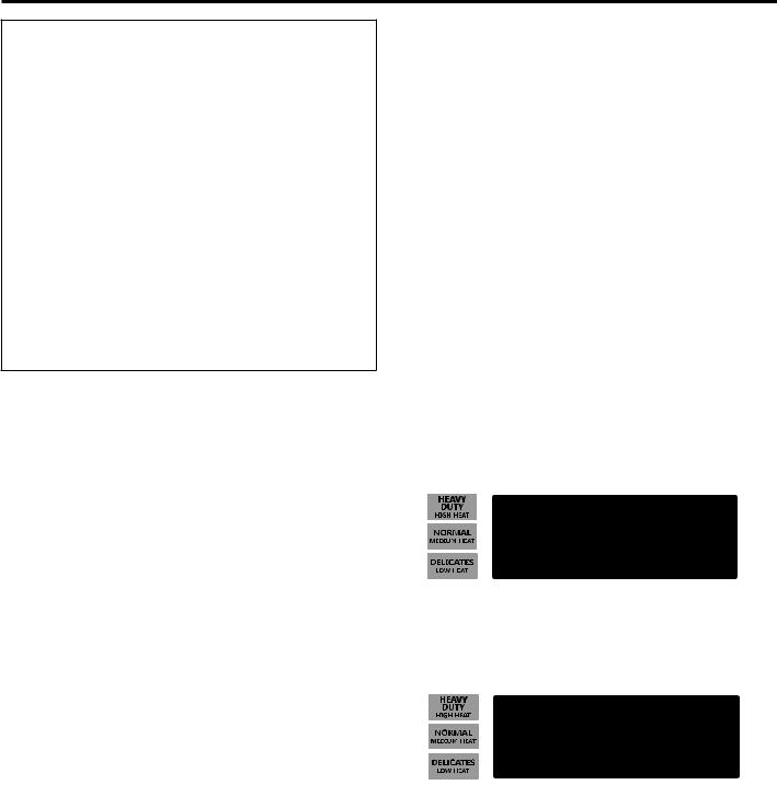
1.The HEAVY DUTY button is used to adjust the values associated with set-up code. Pressing the button will change the value by increments. Rapid adjustment is possible by holding down the button.
2.The NORMAL button will advance through the set-up codes. Pressing the button will advance to the next available set-up code. Holding down the NORMAL button will automatically advance through the set-up codes at a rate faster than 1 per second.
3.The DELICATES button is used to select or deselect options.
Start Operating Set-up
■■Single Load Models: Insert service door key, turn, and lift to remove service door.
IMPORTANT: The console must not be opened unless power is first removed from the dryer. To access connector AA1:
gUnplug dryer or disconnect power.
gOpen console, disconnect plug on AA1, close console.
gPlug in dryer or reconnect power.
The dryer is now in the set-up mode.
NOTE: This dryer is preset at the factory and does not require any programming. However, if you want to change the settings, follow the “Set-Up Codes” guide to the right.
■■Units are pre-set at the factory for fixed cycle price with top off.
Set-Up Codes
■■The NORMAL button will advance you from code to code. ■■The HEAVY DUTY button will change the code value. ■■The DELICATES button will select or deselect options.
The set-up code is indicated by the one or two left-hand characters. The set-up code value is indicated by the two or three right-hand characters.
Code Explanation
606 REGULAR CYCLE PRICE
606Represents the number of quarters (coin 1) needed to start the dryer; may adjust from 0–39 (See VALUE OF COIN 1 b.05). Advance from 0–39 by pressing the HEAVY DUTY button. Factory default of 6 quarters = $1.50.
•Press the NORMAL button once to advance to next code.
705 REGULAR DRY TIME
705Represents the number of minutes per quarter (coin 1). Factory default of 5 minutes per coin.
Example: 6 quarters x 5 minutes = 30 minutes.
By pressing the HEAVY DUTY button, value adjusts from 1–75 minutes.
•Press the NORMAL button once to advance to next code.
800 TYPE OF DRYER PRICING
800Fixed Cycle with Top Off. For detailed description, see “General User Information.”
•Press the NORMAL button once to advance to next code.
9 00 CYCLE COUNTER OPTION
This option is either NOT SELECTED “OFF” or SELECTED “ON.”
9 00 Not Selected “OFF.”
9 0C Selected “ON” and not able to be deselected.
•Press the DELICATES button 3 consecutive times to select “ON.” Once selected “ON” it cannot be deselected.
•Press the NORMAL button once to advance to next code.
If cycle counter (9 0C) is selected, the following is true:
1 00 |
Cycles in HUNDREDS |
1 02 |
= 200 |
2 00 |
Cycles in ONES |
2 25 |
= 25 |
TOTAL CYCLES = 225
This is “VIEW ONLY” and cannot be cleared.
• Press the NORMAL button once to advance to next code.
23
ELECTRONIC CONTROL SETUP INSTRUCTIONS (PD & PN MODELS ONLY)
Code Explanation
1. 00 MONEY COUNTER OPTION
This option is either NOT SELECTED “OFF” or SELECTED “ON.”
1. 00 Not Selected “OFF.”
1. 0C Selected “ON.”
•Press the DELICATES button 3 consecutive times to select “ON” and 3 consecutive times to remove (Not Selected “OFF”). Counter resets by going from “OFF” to “ON.”
1.C0 Selected “ON” and not able to be deselected.
•To select “ON” and not able to be deselected, first select “ON,” then within 2 seconds, press the DELICATES button twice, the HEAVY DUTY button once, and exit set-up mode.
•Press the NORMAL button once to advance to next code.
2.00 SPECIAL PRICING OPTIONS
This option is either NOT SELECTED “OFF” or
SELECTED “ON.”
2.00 Not Selected “OFF,” and next available code will be A.00.
2. SP Selected “ON.”
•Press the DELICATES button once to change this selection.
If SPECIAL PRICING OPTION is selected, there is access to codes “3.XX” through “9.XX.”
•Press the NORMAL button once to advance to next code.
If money counter (1.0C or 1.C0) is selected, the following is true:
3 00 |
Dollars in HUNDREDS |
3 01 = $ |
100.00 |
4 00 |
Dollars in ONES |
4 68 = $ |
68.00 |
5 00 |
Number of CENTS |
5 75 = $ |
00.75 |
|
|
|
|
TOTAL = $168.75
OPTIONS 3.XX – 9.XX TO USE IF SPECIAL PRICING IS SELECTED
Code Explanation
3.06SPECIAL CYCLE PRICE
3.06Represents the number of quarters (coin 1) to start the dryer; may adjust from 0–39. (See VALUE OF COIN 1 b.05.)
•Advance from 0–39 by pressing the HEAVY DUTY button. Factory default of 6 quarters = $1.50.
•Press the NORMAL button once to advance to next code.
4.05SPECIAL DRY TIME
4.05Represents the number of minutes per quarter (coin 1).
•Factory default of 5 minutes per coin. Example: 6 quarters x 5 minutes = 30 minutes.
•By pressing the HEAVY DUTY button, the value can be adjusted from 1–75 minutes.
•Press the NORMAL button once to advance to next code.
5. 00 TIME-OF-DAY CLOCK, MINUTES
5.00 This is the TIME-OF-DAY CLOCK, minute setting; select 0–59 minutes by pressing the HEAVY DUTY button.
•Press the NORMAL button once to advance to next code.
6.00 TIME-OF-DAY CLOCK, HOURS
NOTE: Uses military time or 24 hr. clock.
6.00 This is the TIME-OF-DAY CLOCK, hour setting; select 0–23 hours by pressing the HEAVY DUTY button.
•Press the NORMAL button once to advance to next code.
24

ELECTRONIC CONTROL SETUP INSTRUCTIONS (PD & PN MODELS ONLY)
Code Explanation
7. 00 SPECIAL PRICE START HOUR
NOTE: Uses military time or 24 hr. clock.
7.00 This is the start hour; 0–23 hours.
•Select START HOUR by pressing the HEAVY DUTY button.
•Press the NORMAL button once to advance to next code.
8.00 SPECIAL PRICE STOP HOUR
NOTE: Uses military time or 24 hr. clock.
8.00 This is the stop hour; 0–23 hours.
•Select STOP HOUR by pressing the HEAVY DUTY button.
•Press the NORMAL button once to advance to next code.
9.10 SPECIAL PRICE DAY
9.10 This represents the day of the week and whether special pricing is selected for that day. A number followed by “0” indicates no selection that particular day (9.10). A number followed by an “S” indicates selected for that day (9.1S). Days of the week (1–7) are selected by pressing the HEAVY DUTY button. Press the DELICATES button once to select special pricing for each day chosen.
When exiting set-up code “9,” the display must show the current day of week:
DISPLAY |
DAY OF WEEK |
CODE (selected) |
|
|
|
10 |
Day 1 = Sunday |
1S |
20 |
Day 2 = Monday |
2S |
30 |
Day 3 = Tuesday |
3S |
40 |
Day 4 = Wednesday |
4S |
50 |
Day 5 = Thursday |
5S |
60 |
Day 6 = Friday |
6S |
70 |
Day 7 = Saturday |
7S |
•Press the NORMAL button once to advance to next code.
A.00 VAULT VIEWING OPTION
This option is either NOT SELECTED “OFF” or
SELECTED “ON.”
A. 00 Not Selected “OFF.”
A. SC Selected “ON.”
•Press the DELICATES button once to change this selection. When selected, the money and/or cycle counts will be viewable (if counter option(s) is selected) when the coin box is removed.
•Press the NORMAL button once to advance to next code.
Code Explanation
b. 05 VALUE OF COIN 1
b.05 This represents the value of coin 1 in number of nickels: 05 = $0.25.
•By pressing the HEAVY DUTY button, there is an option of 1–199 nickels.
•Press the NORMAL button once to advance to next code.
C. 20 VALUE OF COIN 2/VALUE OF DRYER TOP OFF
C.20 This represents the value of coin 2 in number of nickels: 20 = $1.00.
For models using Enhanced Debit, this field represents the value of top off in nickels.
•By pressing the HEAVY DUTY button, there is an option of 1–199 nickels.
•Press the NORMAL button once to advance to next code.
d.00 |
COIN SLIDE OPTION |
|
This option is either NOT SELECTED “OFF” or |
|
SELECTED “ON.” |
|
|
d.00 |
Not Selected “OFF.” |
d.CS |
Selected “ON.” |
|
• Press the DELICATES button 3 consecutive times |
for this selection. When coin slide mode is selected, set “b.” equal to value of slide in nickels. Set “606” (REGULAR CYCLE PRICE) and “3.06” (SPECIAL CYCLE PRICE) to number of slide operations.
NOTE: If the installer sets up “CS” on a coin drop model, it will not register coins.
•Press the NORMAL button once to advance to next code.
E.00 ADD COINS OPTION
This option is either NOT SELECTED “OFF” or SELECTED “ON.” This option causes the customer display to show the number of coins (coin 1) to enter, rather than the dollars-and-cents amount. The number in the display changes as the coins are accepted.
E. 00 Not Selected “OFF.”
E. AC Selected “ON.”
•Press the DELICATES button 3 consecutive times to change this selection.
•Press the NORMAL button once to advance to next code.
25

ELECTRONIC CONTROL SETUP INSTRUCTIONS (PD & PN MODELS ONLY)
Code |
Explanation |
|
|
J. Cd |
PAYMENT MODE (COIN/DEBIT OPTION) |
|
|
J. Cd |
Both coin and debit selected. Press the DELICATES |
|
button 3 consecutive times to change this selection. |
J. C_ |
Coins selected, debit disabled. Press the DELICATES |
|
button 3 consecutive times to change this selection. |
J._d |
Debit Card selected, coins disabled. Press the |
|
DELICATES button 3 consecutive times to change |
|
this selection. |
J. Ed |
Enhanced Debit is self-selected when a Generation |
|
2 card reader is installed in the dryer. The Ed option |
|
cannot be manually selected or deselected. |
•Press the NORMAL button once to advance to next code.
L.00 PRICE SUPPRESSION OPTION
This option is either NOT SELECTED “OFF” or SELECTED “ON.” This option causes the customer display to show “ADD” or “AVAILABLE” rather than the amount of money to add. (Used mainly in debit installations.)
L. 00 Not Selected “OFF.”
L. PS Selected “ON.”
•Press the DELICATES button once to change this selection.
•Press the NORMAL button once to advance to next code.
n.CE CLEAR ESCROW OPTION
This option is either NOT SELECTED “OFF” or SELECTED “ON.” When selected, money held in escrow for 30 minutes without further escrow or cycle activity will be cleared.
n. 00 Not Selected “OFF.” n. CE Selected “ON.”
•Press the DELICATES button once to change this selection.
•Press the NORMAL button once to advance to next code.
END of SET-UP PROCEDURES
EXIT FROM SET-UP MODE
Single-Load Models: Reinstall access door.
DIAGNOSTIC GUIDE
If the set-up mode is entered and one of the following has occurred, the appropriate diagnostic code will be in the display.
SINGLE DRYERS
CODE |
EXPLANATION |
|
|
d1 |
Dryer door sense error on |
|
control board or due to power |
|
line interference (cycles and |
|
price display disabled until |
|
diagnostic code is manually |
|
cleared). |
|
|
d4 |
Dryer motor control circuit |
|
error (cycles and customer |
|
display disabled until |
|
diagnostic code is manually |
|
cleared). |
|
|
d5 |
Blocked coin 1 or coin drop |
|
control circuit failure (coin |
|
recognition and customer |
|
display disabled while |
|
blockage persists). |
|
|
d9 |
Voltage detected below |
|
90 VAC for 8 seconds. |
|
|
d12 |
Motor sense error on control |
|
board or due to power line |
|
interference (cycles and |
|
customer display disabled until |
|
diagnostic code is manually |
|
cleared). |
|
|
d13 |
Blocked coin 2 or coin drop |
|
control circuit failure (coin |
|
recognition and price display |
|
disabled while blockage |
|
persists). |
|
|
d16 |
Not receiving communications |
|
from installed debit card reader |
|
in Enhanced (Generation 2) |
|
Debit mode. |
|
|
26
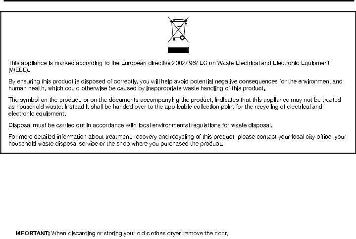
DRYER DISPOSAL
MODEL NOMENCLATURE:
MDG – Maytag Gas |
CS – Coin Slide |
A – Series Revision |
||||
MDE – Maytag Electric |
MN – Timer Non-Pay |
G – Global |
||||
20 – Model Type Number |
PD – Coin Drop |
W – White |
||||
|
|
|
PN – Electronic Non-Pay |
|
||
|
|
|
|
|
|
|
|
|
|
|
|
|
|
|
|
|
|
|
|
|
|
|
|
|
|
|
|
27

MAYTAG COMMERCIAL LAUNDRY
LIMITED WARRANTY
IF YOU NEED SERVICE:
Contact your authorized Maytag Commercial Laundry distributor. To locate your authorized Maytag Commercial Laundry distributor, visit www.maytagcommerciallaundry.com.
For written correspondence:
Maytag Commercial Laundry Service Department
2000 N M 63
Benton Harbor, Michigan 49022-2632 USA
|
FIVE YEAR LIMITED WARRANTY |
WHAT IS COVERED |
WHAT IS NOT COVERED |
FIVE YEAR LIMITED WARRANTY |
1. All other costs including labor, transportation, shipping, or custom duties for |
(PARTS ONLY — LABOR NOT INCLUDED) |
covered parts. |
For the first five years from the original date of purchase, when this commercial appliance is installed, maintained, and operated according to the instructions attached to or furnished with the product, Maytag brand of Whirlpool Corporation (hereafter “Maytag”) will pay for factory specified replacement parts to correct defects in materials or workmanship that existed when this commercial appliance was purchased. This limited warranty does not include labor.
YOUR SOLE AND EXCLUSIVE REMEDY UNDER THIS LIMITED WARRANTY SHALL BE PRODUCT REPAIR AS PROVIDED HEREIN. Maytag recommends that you use an “authorized” service provider to diagnose and repair your Commercial Laundry product.
Maytag will not be responsible under this warranty to provide additional replacement parts as a result of incorrect diagnosis or repair by an “unauthorized” service company. Except in the European Union, this limited warranty is valid only when the commercial appliance is used in the country in which it was purchased. This limited warranty is effective from the date of the original consumer purchase. Proof
of original purchase date is required to obtain service under this limited warranty.
2.Factory specified replacement parts if this commercial appliance is used for other than normal, commercial use or when it is used in a manner that is inconsistent to published user or operator instructions and/or installation instructions.
3.Service calls to correct the installation of your commercial appliance, to instruct you on how to use your commercial appliance, to replace or repair house fuses, or to correct external wiring or plumbing.
4.Service calls to repair or replace appliance light bulbs, air filters, or water filters. Consumable parts are excluded from warranty coverage.
5.Damage resulting from improper handling of product during delivery, theft, accident, alteration, misuse, abuse, fire, flood, acts of God, improper installation, installation not in accordance with local electrical or plumbing codes, or use of products not approved by Maytag.
6.Pick up and delivery. This commercial appliance is designed to be repaired on location.
7.Repairs to parts or systems resulting from unauthorized modifications made to the commercial appliance.
8.The removal and reinstallation of your commercial appliance if it is installed in an inaccessible location or is not installed in accordance with published installation instructions.
9.Damage resulting from exposure to chemicals.
10.Changes to the building, room, or location needed in order to make the commercial appliance operate correctly.
11.Factory specified replacement parts on commercial appliances with original model/serial numbers that have been removed, altered, or cannot be easily determined.
12.Discoloration, rust, or oxidation of stainless steel surfaces.
13.Factory specified replacement parts as a result of incorrect diagnosis or repair by an “unauthorized” service company.
The cost of repair or replacement under these excluded circumstances shall be borne by the customer.
DISCLAIMER OF IMPLIED WARRANTIES
IMPLIED WARRANTIES, INCLUDING ANY IMPLIED WARRANTY OF MERCHANTABILITY OR IMPLIED WARRANTY OF FITNESS FOR A PARTICULAR PURPOSE, ARE LIMITED TO FIVE YEARS OR THE SHORTEST PERIOD ALLOWED BY LAW. Some locations may not allow limitations on the duration of implied warranties of merchantability or fitness, so this limitation may not apply to you. This warranty gives you specific legal rights, and you also may have other rights that vary.
DISCLAIMER OF REPRESENTATIONS OUTSIDE OF WARRANTY
Maytag makes no representations about the quality, durability, or need for service or repair of this major appliance other than the representations contained in this Warranty. If you want a longer or more comprehensive warranty than the limited warranty that comes with this major appliance, you should ask your retailer about buying an extended warranty. The benefits to you given by this warranty are in addition to other rights and remedies available to you under a law in relation to the goods or service to which this warranty relates. Please contact Maytag for further information on warranty terms.
LIMITATION OF REMEDIES; EXCLUSION OF INCIDENTAL AND CONSEQUENTIAL DAMAGES
YOUR SOLE AND EXCLUSIVE REMEDY UNDER THIS LIMITED WARRANTY SHALL BE PRODUCT REPAIR AS PROVIDED HEREIN. MAYTAG SHALL NOT BE LIABLE FOR INCIDENTAL OR CONSEQUENTIAL DAMAGES. Some locations do not allow the
exclusion or limitation of incidental or consequential damages, so these limitations and exclusions may not apply to you. This warranty gives you specific legal rights, and you also may have other rights that vary by location.
04/17
28

SECURITE DU SECHE-LINGE
AVERTISSEMENT – “Risque d’incendie”
Ceci est un symbole supplémentaire d’alerte de sécurité vous signalant un risque d’incendie.
AVERTISSEMENT - “Risque d'incendie”
-L'installation du sèche-linge et la maintenance doivent être réalisées par un installateur agréé par Whirlpool.
-Installer le sèche-linge conformément aux instructions du fabricant et aux réglementations locales.
tendance à se plier, s'écraser facilement et re
-Pour réduire le risque de blessures graves ou de mort, respecter toutes les instructions d'installation.
-Conserver ces instructions.
29
SECURITE DU SECHE-LINGE
■■On recommande que le propriétaire place les instructions à l’usage du client en un lieu bien visible, au cas où le client percevrait une odeur de gaz. Ces renseignements doivent être obtenus auprès de votre fournisseur en gaz.
■■Placer l’avertissement qui suit à un endroit bien visible.
POUR VOTRE SECURITE
1.NE PAS UTILISER OU REMISER D’ESSENCE OU AUTRES MATÉRIAUX INFLAMMABLES DANS CET APPAREIL MÉNAGER OU À PROXIMITÉ DE CELUI-CI.
2.NE PAS VAPORISER D’AÉROSOLS À PROXIMITÉ DE CET APPAREIL MÉNAGER LORSQU’IL EST EN FONCTIONNEMENT.
3.NE PAS MODIFIER CET APPAREIL MÉNAGER.
 AVERTISSEMENT :
RISQUE D'INCENDIE OU D'EXPLOSION
Le non-respect des avertissements de sécurité peut causer des dommages à la propriété, des blessures graves, voire la mort.
–Ne pas entreposer ou utiliser de l’essence ou d’autres vapeurs ou liquidesinflammables à proximité de cet appareil ou de tout autre appareil électroménager.
–QUE FAIRE DANS LE CAS D’UNE ODEUR DE GAZ :
• Ne pas tenter d’allumer un appareil.
•Ne pas toucher à un commutateur électrique; ne pas utiliser le téléphone se trouvant sur les lieux.
•Évacuer tous les gens de la pièce, de l’édifice ou du quartier.
•Appeler immédiatement le fournisseur de gaz d’un téléphone voisin. Suivre ses instructions.
•À défaut de joindre votre fournisseur de gaz, appeler les pompiers.
–L’installation et l’entretien doivent être effectués par un installateur qualifié, uneagence de service ou le fournisseur de gaz.
IMPORTANT : Pour mettre l’ancien sèche-linge au rebut ou pour la remiser, enlever la porte.
30
 Loading...