


MDB8959AWS7
Maytag MDB8959AWS7, MDB8959AWB7, MDB7760AWS2, MDB7759AWS4, MDB7759AWB4 Installation Guide
...
INSTALLATIONINSTRUCTIONS
UNDERCOUNTERDISHWASHER
STAINLESSSTEELGIANT TUBMODELS
INSTRUCTIONSD'INSTALLATION
LAVE-VAISSELLESOUSPLANDETRAVAIL
MODELESGEANTSDECUVE D'ACIER INOXYDABLE
Table of Contents .............................................................. 2
Table des matieres .......................................................... 23
W10329314A
TABLEOF CONTENTS
DISHWASHER SAFETY ............................................................................... 2
INSTALLATION REQUIREMENTS ............................................................. 3
Tools and Parts ......................................................................................... 3
Location Requirements ............................................................................. 4
Drain Requirements .................................................................................. 6
Water Supply Requirements ..................................................................... 6
Electrical Requirements ............................................................................ 6
INSTALLATION INSTRUCTIONS ............................................................... 7
Prepare Cabinet Opening--Existing Utilities ............................................ 7
Prepare Cabinet Opening-- New Utilities ................................................. 7
Prepare and Route Water Line ................................................................. 8
Install Drain Hose ...................................................................................... 9
Install Moisture Barrier (under a wood countertop) ................................ 11
Prepare Dishwasher ................................................................................ 11
INSTALLATION INSTRUCTIONS (CONT.)
Make Power Supply Cord Connection .................................................. 12
Determine Cabinet Opening ................................................................... 14
Install Door Handle (on some models) ................................................... 14
Choose Attachment Option .................................................................... 15
Move Dishwasher Close to Cabinet Opening ........................................ 16
Connect to Water Supply ....................................................................... 18
Connect to Drain ..................................................................................... 18
Make Direct Wire Electrical Connection ................................................. 19
Secure Dishwasher in Cabinet Opening ................................................ 20
Complete Installation .............................................................................. 21
Check Operation ..................................................................................... 22
If Dishwasher Does Not Operate ............................................................ 22
Additional Tips ........................................................................................ 22
DISHWASHERSAFETY
Your safety and the safety of others are very important.
We have provided many important safety messages in this manual and on your appliance. Always read and obey all safety
messages.
This is the safety alert symbol.
This symbol alerts you to potential hazards that can kill or hurt you and others.
All safety messages will follow the safety alert symbol and either the word "DANGER" or "WARNING."
These words mean:
You can be killed or seriously injured if you don't immediately
follow instructions.
You can be killed or seriously injured if you don't follow
instructions.
All safety messages will tell you what the potential hazard is, tell you how to reduce the chance of injury, and tell you what can
happen if the instructions are not followed.
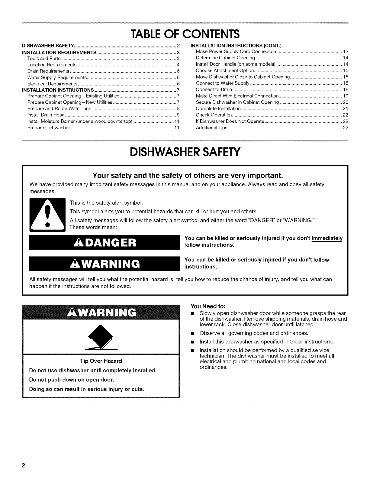
Tip Over Hazard
Do not use dishwasher until completely installed.
Do not push down on open door.
Doing so can result in serious injury or cuts.
You Need to:
• Slowly open dishwasher door while someone grasps the rear
of the dishwasher. Remove shipping materials, drain hose and
lower rack. Close dishwasher door until latched.
• Observe all governing codes and ordinances.
• Install this dishwasher as specified in these instructions.
• Installation should be performed by a qualified service
technician. The dishwasher must be installed to meet all
electrical and plumbing national and local codes and
ordinances.
2
INSTALLATION
REQUIREMENTS
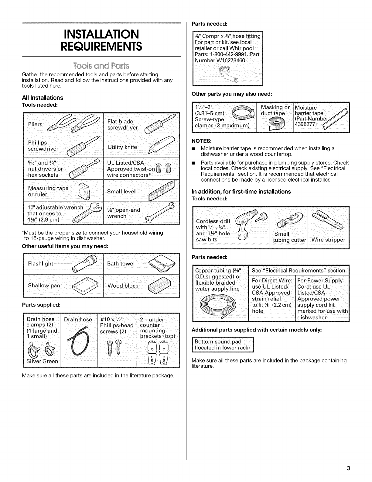
Gather the recommended tools and parts before starting
installation• Read and follow the instructions provided with any
tools listed here.
All Installations
Tools needed:
Piers
Phillips
screwdriver
_,%"and ¼"
nut drivers or
hex sockets
Measuring tape
or ruler
10"adjustable wren
that opens to /_'_
1V8 (2.9 cm)
Flat-blade
screwdriver
(
Utility knife
UL Listed/CSA _
Approved twist-on _
wire connectors*
Small level
%" open-end
wrench
*Must be the proper size to connect your household winng
to 16-gauge wiring in dishwasher•
Other useful items you may need:
Parts supplied:
Drain hose Drain hose
clamps (2)
(1 large and
1 small)
Make sure all these parts are included in the literature package•
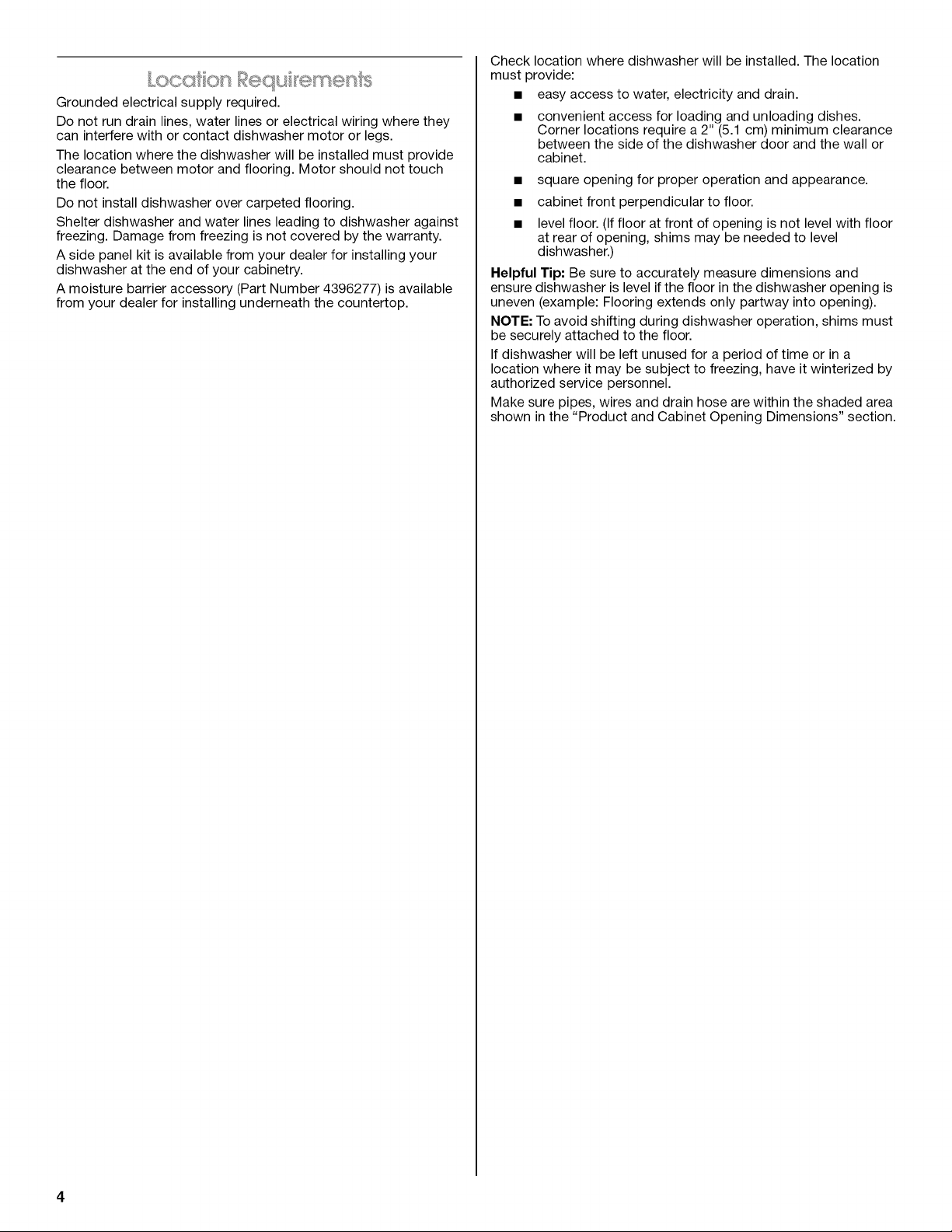
Parts needed:
%1'Compr x ¾, hose fitting
For part or kit, see local
retailer or call Whirlpoo[
Parts: 1-800-442-9991. Part
Number W10273460
Other parts you may also need:
!
1 _l i • .
[
1! ½ -2 Masking or Mo!sture _l
I (3'81-5 Cm)I ducttape I barfiertape /_J
J ScrewLtype .... I(Part aumber/_./ [
[ clamps (3 max!mum)J 14396277)
NOTES:
• Moisture barrier tape is recommended when installing a
dishwasher under a wood countertop.
Parts available for purchase in plumbing supply stores• Check
local codes• Check existing electrical supply• See "Electrical
Requirements" section• It is recommended that electrical
connections be made by a licensed electrical installer•
In addition, for first-time installations
Toolsneeded:
Cordless drill
• 1 u 3 H
wroth Y2, Y4
1 ii
and 1V2 hole
saw bits
Parts needed:
er tubing (3/_!, See ,'Electrical Requirements,, secti0nl
'D'suggested) or For aireCtwire: F0rPower
flexible braided
w...xr x......i., jp.x use UL Listed/ Cord: use UL
°_Y '_ CSAApproved Listed/CSA
@\ strain relief I ApproVed power
((((E_(. _)_/))))j;) tofit _,, (2.2 Cm) I SUpply C0[d k t
hole I marked for use with
-_ I Idishwasher
Additional parts supplied with certain models only:
I Bottom sound pad I
[ (located in lower rack) J
Make sure all these parts are included in the package containing
literature•
@roundedelectricalsupplyrequired.
Donotrundrainlines,waterlinesorelectricalwiringwherethey
caninterferewithorcontactdishwashermotororlegs.
Thelocationwherethedishwasherwillbeinstalledmustprovide
clearancebetweenmotorandflooring.Motorshouldnottouch
thefloor.
Donotinstalldishwasherovercarpetedflooring.
Shelterdishwasherandwaterlinesleadingtodishwasheragainst
freezing.Damagefromfreezingisnotcoveredbythewarranty.
Asidepanelkitisavailablefromyourdealerforinstallingyour
dishwasherattheendofyourcabinetry.
Amoisturebarrieraccessory(PartNumber4396277)isavailable
fromyourdealerforinstallingunderneaththecountertop.
Checklocationwheredishwasherwillbeinstalled.Thelocation
mustprovide:
• easyaccesstowater,electricityanddrain.
convenientaccessforloadingandunloadingdishes.
Cornerlocationsrequirea2"(5.1cm)minimumclearance
betweenthesideofthedishwasherdoorandthewallor
cabinet.
• squareopeningforproperoperationandappearance.
• cabinetfrontperpendiculartofloor.
• levelfloor.(Ifflooratfrontofopeningisnotlevelwithfloor
atrearofopening,shimsmaybeneededtolevel
dishwasher.)
HelpfulTip:Besuretoaccuratelymeasuredimensionsand
ensuredishwasherislevelifthefloorinthedishwasheropeningis
uneven(example:Flooringextendsonlypartwayintoopening).
NOTE:Toavoidshiftingduringdishwasheroperation,shimsmust
besecurelyattachedtothefloor.
Ifdishwasherwillbeleftunusedforaperiodoftimeorina
locationwhereitmaybesubjecttofreezing,haveitwinterizedby
authorizedservicepersonnel.
Makesurepipes,wiresanddrainhosearewithintheshadedarea
showninthe"ProductandCabinetOpeningDimensions"section.
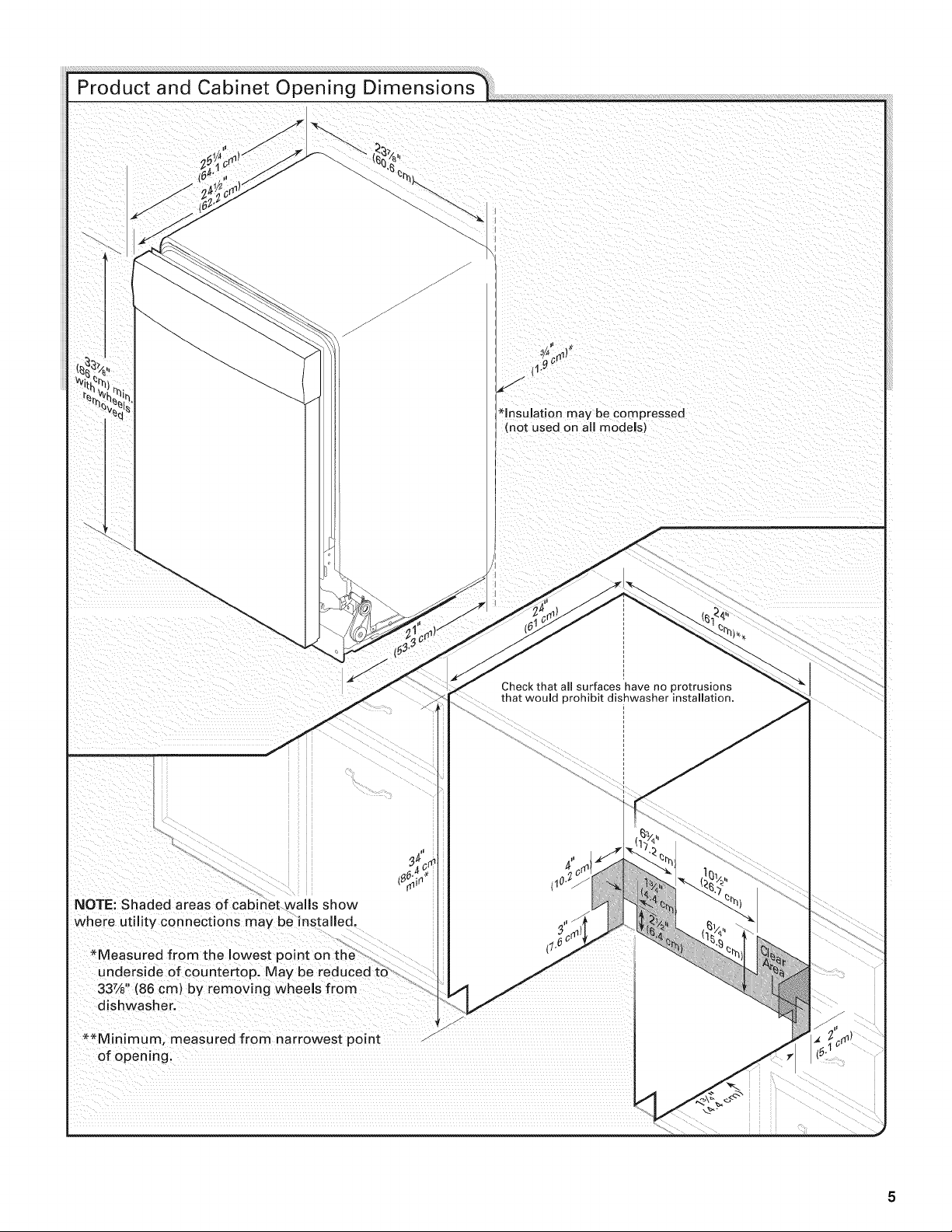
*insulation may be compressed
(not used on all models)
NOTE: Shaded areas of cabinet walls show
where utility connections may be installed.
*Measured from the lowest point on the ,
underside of countertop. May be reduced :[0
337/8'' r wn wh I rom
(86cm) by emo i g eesf
dishwasher.
**Minimum, measured from narrowest point
of opening.
z
/
Check that all surfaces have no protrusions
that would prohibit dishwasher installation.
J
A new drain hose is supplied with your dishwasher. If drain
hose is not long enough, use a new drain hose with a
maximum length of 12 ft (3.7 m) (Part Number 3385556) that
meets all current AHAM/IAPMO test standards, is resistant to
heat and detergent, and fits the 1" (2.5 cm) drain connector of
the dishwasher.
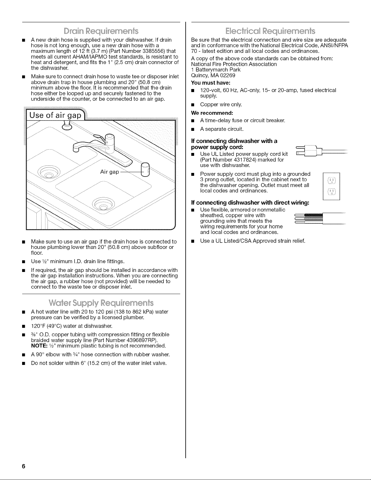
Make sure to connect drain hose to waste tee or disposer inlet
above drain trap in house plumbing and 20" (50.8 cm)
minimum above the floor. It is recommended that the drain
hose either be looped up and securely fastened to the
underside of the counter, or be connected to an air gap.
Make sure to use an air gap if the drain hose is connected to
house plumbing lower than 20" (50.8 cm) above subfloor or
floor.
Use 1/2"minimum I.D. drain line fittings.
If required, the air gap should be installed in accordance with
the air gap installation instructions. When you are connecting
the air gap, a rubber hose (not provided) will be needed to
connect to the waste tee or disposer inlet.
pp)y 58eq(s emen s
A hot water line with 20 to 120 psi (188 to 862 kPa) water
pressure can be verified by a licensed plumber.
120°F (49°C) water at dishwasher.
3/8"O.D. copper tubing with compression fitting or flexible
braided water supply line (Part Number 4396897RP).
NOTE: 1/2"minimum plastic tubing is not recommended.
A 90° elbow with 3/4"hose connection with rubber washer.
Do not solder within 6" (15.2 cm) of the water inlet valve.
Be sure that the electrical connection and wire size are adequate
and in conformance with the National Electrical Code, ANSI/NFPA
70 - latest edition and all local codes and ordinances.
A copy of the above code standards can be obtained from:
National Fire Protection Association
1 Batterymarch Park
Quincy, MA 02269
You must have:
• 120-volt, 60 Hz, AC-only, 15- or 20-amp, fused electrical
supply.
• Copper wire only.
We recommend:
• A time-delay fuse or circuit breaker.
• Aseparate circuit.
If connecting dishwasher with a
power supply cord:
Use UL Listed power supply cord kit
(Part Number 4317824) marked for
use with dishwasher.
Power supply cord must plug into a grounded
3 prong outlet, located in the cabinet next to
the dishwasher opening. Outlet must meet all
local codes and ordinances.
If connecting dishwasher with direct wiring:
• Use flexible, armored or nonmetallic
sheathed, copper wire with
grounding wire that meets the
wiring requirements for your home
and local codes and ordinances.
• Use a UL Listed/CSA Approved strain relief.
6
INSTALLATIONINSTRUCTIONS
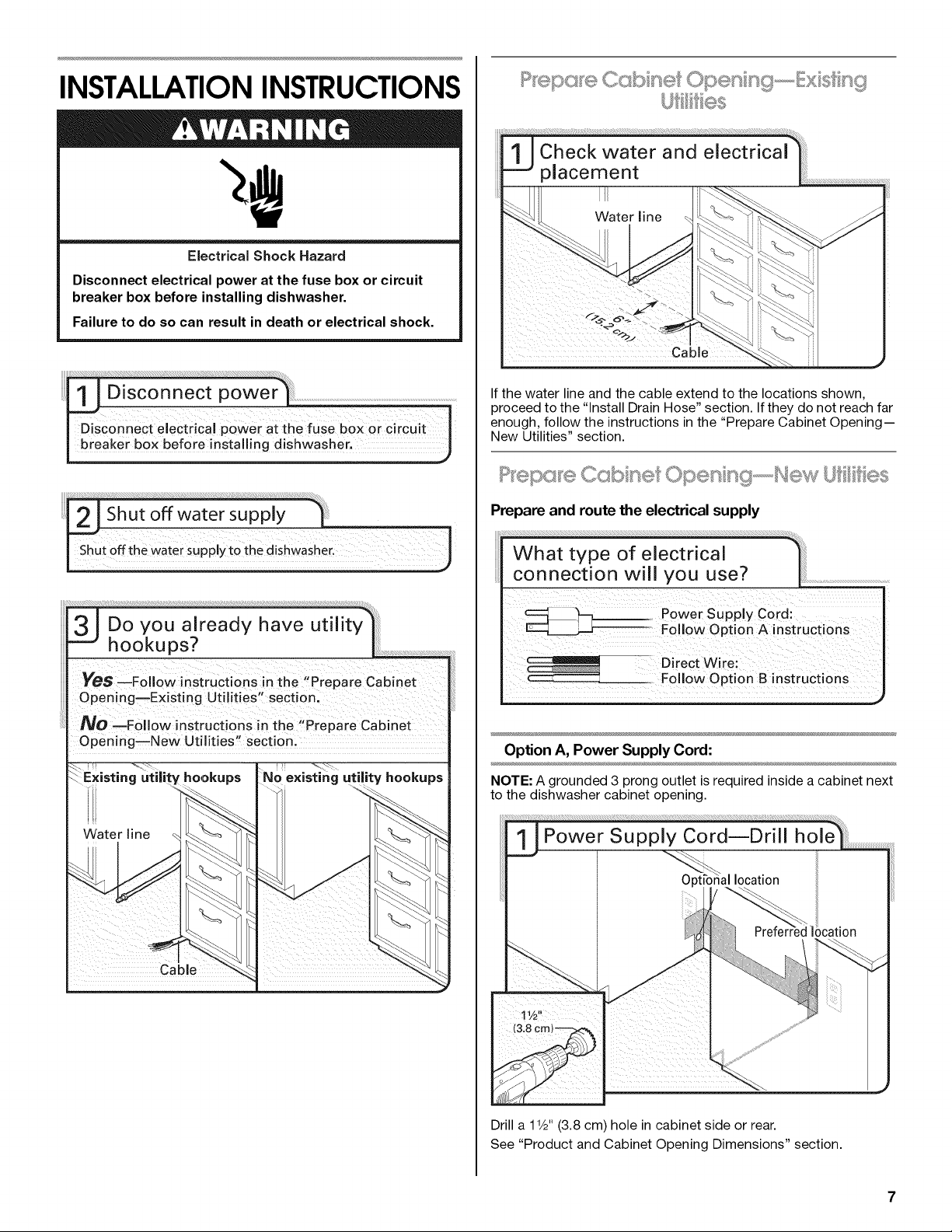
Electrical Shock Hazard
Disconnect electrical power at the fuse box or circuit
breaker box before installing dishwasher.
Failure to do so can result in death or electrical shock.
....i ....!i
I DisconneCt eleCtrical power a
breaker box before installing
JDo you already have utilit
hookups?
YeS --Follow instructions in the "Prepare Cabinet
Opening--Existing Utilities" section.
NO --FoJlow instructions in the "Prepare Cabinet
Opening--New Utilities" sectio n.
:ility hookups
If the water line and the cable extend to the locations shown,
proceed to the "Install Drain Hose" section. If they do not reach far
enough, follow the instructions in the "Prepare Cabinet Opening--
New Utilities" section.
Prepare and route the electrical supply
What type of electricaJ
connection will you use?
s,pp yCo di
FolJow Option A instructions
Direct wire
FolJoW Option B instructions
Option A, Power Supply Cord:
NOTE: A grounded 3 prong outlet is required inside a cabinet next
to the dishwasher cabinet opening.
Drill a 1Y2"(3.8 cm) hole in cabinet side or rear.
See "Product and Cabinet Opening Dimensions" section.
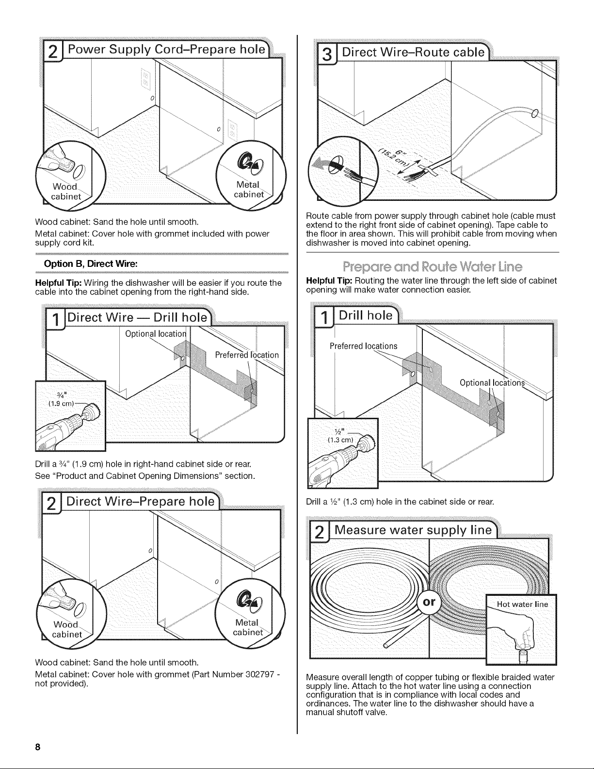
Woodcabinet:Sandtheholeuntilsmooth.
Metalcabinet:Coverholewithgrommetincludedwithpower
supplycordkit.
OptionB, Direct Wire:
Helpful Tip: Wiring the dishwasher will be easier if you route the
cable into the cabinet opening from the right-hand side.
Drill a 3/4"(1.9 cm) hole in right-hand cabinet side or rear.
See "Product and Cabinet Opening Dimensions" section.
Wood cabinet: Sand the hole until smooth.
Metal cabinet: Cover hole with grommet (Part Number 302797 -
not provided).
Route cable from power supply through cabinet hole (cable must
extend to the right front side of cabinet opening). Tape cable to
the floor in area shown. This will prohibit cable from moving when
dishwasher is moved into cabinet opening.
epG e e
L%e
Helpful Tip: Routing the water line through the left side of cabinet
opening will make water connection easier.
Drill a V2"(1.3 cm) hole in the cabinet side or rear.
Measure overall length of copper tubing or flexible braided water
supply line. Attach to the hot water line using a connection
configuration that is in compliance with local codes and
ordinances. The water line to the dishwasher should have a
manual shutoff valve.
8
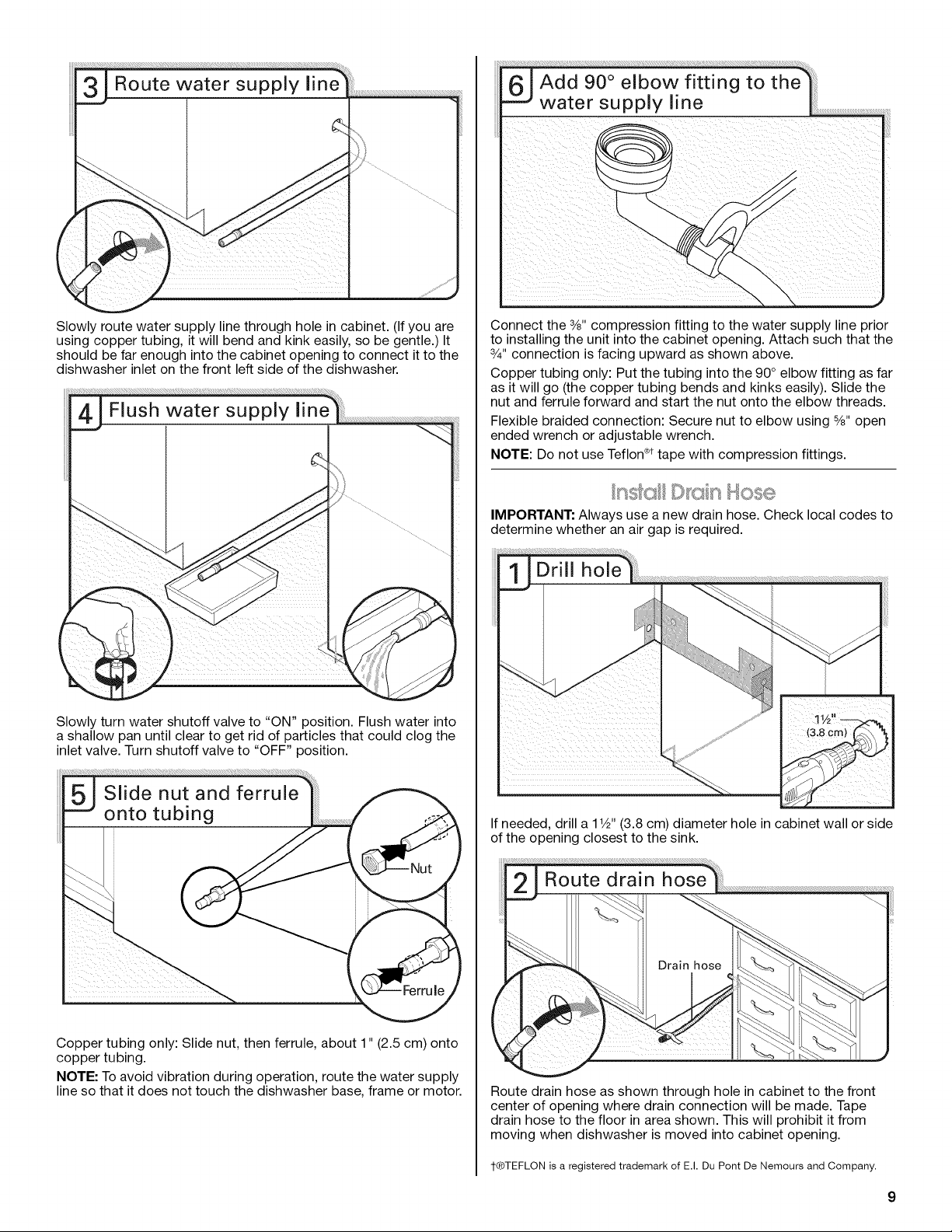
Slowly route water supply line through hole in cabinet. (If you are
using copper tubing, it will bend and kink easily, so be gentle.) It
should be far enough into the cabinet opening to connect it to the
dishwasher inlet on the front left side of the dishwasher.
Slowly turn water shutoff valve to "ON" position. Flush water into
a shallow pan until clear to get rid of particles that could clog the
inlet valve. Turn shutoff valve to "OFF" position.
Copper tubing only: Slide nut, then ferrule, about 1" (2.5 cm) onto
copper tubing.
NOTE: To avoid vibration during operation, route the water supply
line so that it does not touch the dishwasher base, frame or motor.
61Add O owf ti;ogtothA
water supply line ...................................................
Connect the 3/8"compression fitting to the water supply line prior
to installing the unit into the cabinet opening. Attach such that the
3/4"connection is facing upward as shown above.
Copper tubing only: Put the tubing into the 90° elbow fitting as far
as it will go (the copper tubing bends and kinks easily). Slide the
nut and ferrule forward and start the nut onto the elbow threads.
Flexible braided connection: Secure nut to elbow using 5/8"open
ended wrench or adjustable wrench.
NOTE: Do not use Teflon ®ttape with compression fittings.
IMPORTANT: Always use a new drain hose. Check local codes to
determine whether an air gap is required.
If needed, drill a 1V2"(3.8 cm) diameter hole in cabinet wall or side
of the opening closest to the sink.
Route drain hose as shown through hole in cabinet to the front
center of opening where drain connection will be made. Tape
drain hose to the floor in area shown. This will prohibit it from
moving when dishwasher is moved into cabinet opening.
1-®TEFLON is a registered trademark of E.I. Du Pont De Nemours and Company.
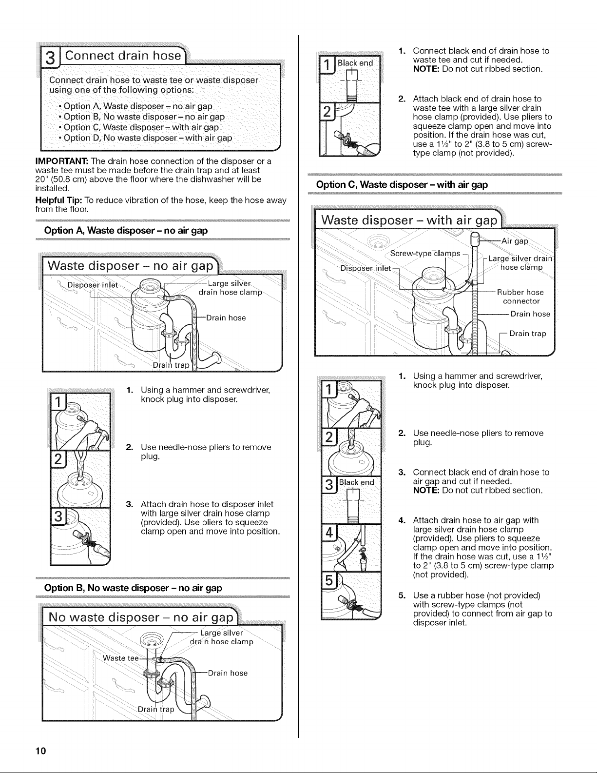
Connect drain hose tO waste tee or waste disposer
uslng one Of the f0110w!ng optionsi
! option A; waste disp0ser- no air gap
, option B, No waste d sposer- no air gap
!Option C; Waste disposer'with air gap
option D, No Waste disP0ser, with air gap
IMPORTANT: The drain hose connection of the disposer or a
waste tee must be made before the drain trap and at least
20" (50.8 cm) above the floor where the dishwasher will be
installed.
Helpful Tip: To reduce vibration of the hose, keep the hose away
from the floor.
Option A, Waste disposer - no air gap
....Drai
1. Using a hammer and screwdriver,
knock plug into disposer.
2. Use needle-nose pliers to remove
plug.
3,
Attach drain hose to disposer inlet
with large silver drain hose clamp
(provided). Use pliers to squeeze
clamp open and move into position.
Option B, No waste disposer - no air gap
1. Connect black end of drain hose to
waste tee and cut if needed.
NOTE: Do not cut ribbed section.
2, Attach black end of drain hose to
waste tee with a large silver drain
hose clamp (provided). Use pliers to
squeeze clamp open and move into
position. If the drain hose was cut,
use a 1V2" to 2" (3.8 to 5 cm) screw-
type clamp (not provided).
Option C, Waste disposer - with air gap
Drain trap
1. Using a hammer and screwdriver,
knock plug into disposer.
2. Use needle-nose pliers to remove
plug.
3. Connect black end of drain hose to
air gap and cut if needed.
NOTE: Do not cut ribbed section.
4,
5,
Attach drain hose to air gap with
large silver drain hose clamp
(provided). Use pliers to squeeze
clamp open and move into position.
If the drain hose was cut, use a 11/2"
to 2" (3.8 to 5 cm) screw-type clamp
(not provided).
Use a rubber hose (not provided)
with screw-type clamps (not
provided) to connect from air gap to
disposer inlet.
10
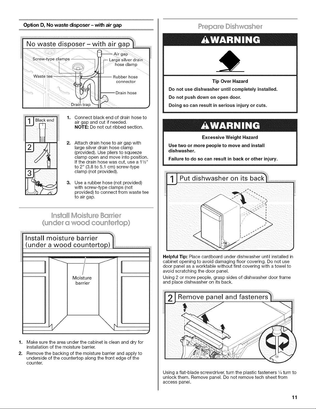
Option D, No waste disposer - with air gap
!;! ;___;i i;A¸!ii!!i;;;;;ii;¸;i; ; i¸_:;I;i_!;;;!;ii_ii;;;,
2.
3.3
Connect black end of drain hose to
air gap and cut if needed.
NOTE: Do not cut ribbed section.
Attach drain hose to air gap with
large silver drain hose clamp
(provided). Use pliers to squeeze
clamp open and move into position.
If the drain hose was cut, use a 1W'
to 2" (3.8 to 5.1 cm) screw-type
clamp (not provided).
Use a rubber hose (not provided)
with screw-type clamps (not
provided) to connect from waste tee
to air gap.
l_ _ _ _ 1/¸ _
nde ' a od count®dop
Moisture
barrier
1=
2.
Make sure the area under the cabinet is clean and dry for
installation of the moisture barrier.
Remove the backing of the moisture barrier and apply to
underside of the countertop along the front edge of the
counter.
Tip Over Hazard
Do not use dishwasher until completely installed.
Do not push down on open door.
Doing so can result in serious injury or cuts.
Excessive Weight Hazard
Use two or more people to move and install
dishwasher.
Failure to do so can result in back or other injury.
Helpful Tip: Place cardboard under dishwasher until installed in
cabinet opening to avoid damaging floor covering. Do not use
door panel as a worktable without first covering with a towel to
avoid scratching the door panel.
Using 2 or more people, grasp sides of dishwasher door frame
and place dishwasher on its back.
Using a flat-blade screwdriver, turn the plastic fasteners 1/4turn to
unlock them. Remove panel. Do not remove tech sheet from
access panel.
11
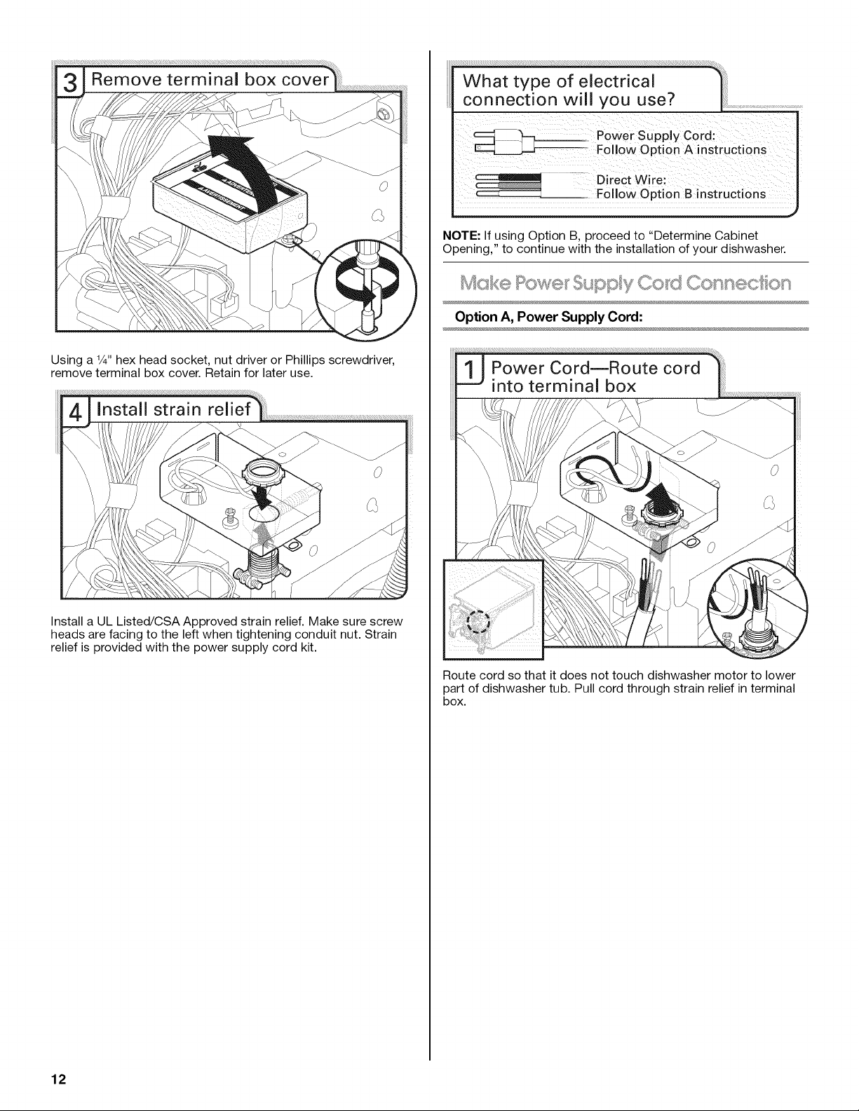
Using a 1/4"hex head socket, nut driver or Phillips screwdriver,
remove terminal box cover. Retain for later use.
0
Install a UL Listed/CSA Approved strain relief. Make sure screw
heads are facing to the left when tightening conduit nut. Strain
relief is provided with the power supply cord kit.
J
NOTE: If using Option B, proceed to "Determine Cabinet
Opening," to continue with the installation of your dishwasher.
Mcsk® Pow®t; Sk_s'sv Co_ Conn®ct on
......... _,_t_,;_'..........
Option A, Power Supply Cord:
Route cord so that it does not touch dishwasher motor to lower
part of dishwasher tub. Pull cord through strain relief interminal
box.
12
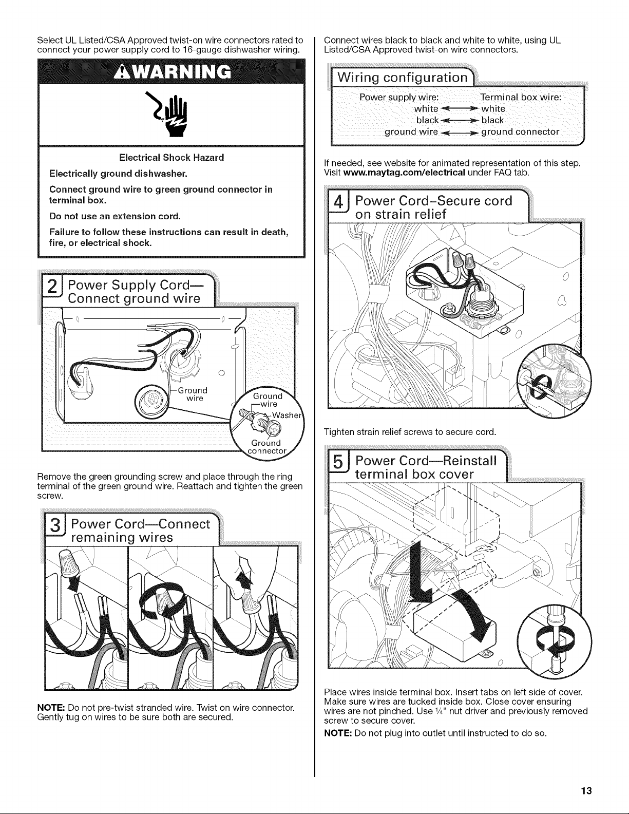
Select UL Listed/CSA Approved twist-on wire connectors rated to
connect your power supply cord to 16-gauge dishwasher wiring.
Electrical Shock Hazard
ElectricMly ground dishwasher.
Connect ground wire to green ground connector in
terminal box.
Do not use an extension cord.
Failure to follow these instructions can result in death,
fire, or electrical shock.
e)
/
Remove the green grounding screw and place through the ring
terminal of the green ground wire. Reattach and tighten the green
screw.
Power Cord--Connect
remaining wires .........................................
NOTE: Do not pre-twist stranded wire. Twist on wire connector.
Gently tug on wires to be sure both are secured.
Connect wires black to black and white to white, using UL
Listed/CSA Approved twist-on wire connectors.
If needed, see website for animated representation of this step.
Visit www.maytag.com/electrical under FAQ tab.
Tighten strain relief screws to secure cord.
Place wires inside terminal box. Insert tabs on left side of cover.
Make sure wires are tucked inside box. Close cover ensuring
wires are not pinched. Use 1/4"nut driver and previously removed
screw to secure cover.
NOTE: Do not plug into outlet until instructed to do so.
13
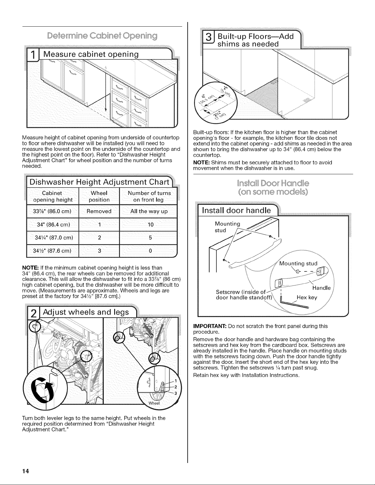
Measure height of cabinet opening from underside of countertop
to floor where dishwasher will be installed (you will need to
measure the lowest point on the underside of the countertop and
the highest point on the floor). Refer to "Dishwasher Height
Adjustment Chart" for wheel position and the number of turns
needed.
! II
33%" (86.0 cm) Removed All the way up
u |
34" (86,4 cm) .1 10
- j
NOTE: If the minimum cabinet opening height is less than
34" (86.4 cm), the rear wheels can be removed for additional
clearance. This will allow the dishwasher to fit into a 337/8'' (86 cm)
high cabinet opening, but the dishwasher will be more difficult to
move. (Measurements are approximate. Wheels and legs are
preset at the factory for 34W' [87.6 cm].)
Adjust wheels and legs
Turn both leveler legs to the same height. Put wheels in the
required position determined from "Dishwasher Height
Adjustment Chart."
Built-up floors: If the kitchen floor is higher than the cabinet
opening's floor - for example, the kitchen floor tile does not
extend into the cabinet opening - add shims as needed in the area
shown to bring the dishwasher up to 34" (86.4 cm) below the
countertop.
NOTE: Shims must be securely attached to floor to avoid
movement when the dishwasher is in use.
(or some
Mounting
stud
Setscrew, (inside
door
IMPORTANT: Do not scratch the front panel during this
procedure.
Remove the door handle and hardware bag containing the
setscrews and hex key from the cardboard box. Setscrews are
already installed in the handle. Place handle on mounting studs
with the setscrews facing down. Push the door handle tightly
against the door. Insert the short end of the hex key into the
setscrews. Tighten the setscrews V4turn past snug.
Retain hex key with Installation Instructions.
14
 Loading...