


Maytag MDET336AYW, MDE3706AYW, MDET236AYW, MDE5806AYK, MDE5806AYW Installation Instructions
...®
Installation
Instructions
Electric Dryer
Keep instructions for future reference. Be sure manual stays with dryer.
Questions?
See the User’s Guide or call Maytag Appliances Sales Company
1-800-688-9900 USA
1-800-688-2002 Canada
1-800-688-2080 TTY USA Only
REMOVE PARTS 1AND CLEAN
DRYER DRUM
Wipe drum with clean rag and soap diluted in warm water to remove any oil used in manufacturing. Make a paste of laundry detergent and clean drum if necessary.
To reverse the direction that door opens, see the User’s Guide.
You'll Need a Few Things Before You Begin
Power Cord (3-wire or 4-wire) and Strain Relief
Screws (supplied)
Duct Tape
Wrench
Screw
Drivers
Level
Optional Kits
Kits are available at extra cost
through your Maytag dealer or
Maytag Customer Assistance at
1-800-688-9900 USA
1-800-688-2002 Canada
1-800-688-2080 TTY USA Only
Directional Exhaust Kit
DK1 Sales Accessory (Directional
Exhaust Kit #528P3).
Flexible Metal Vent Kit
Exhausting the dryer in hard-to- reach locations can be accomplished by installing Kit # 521P3.
Part No. 40136301
Printed in U.S.A. 11/01
CONNECT DRYER 2TO EXHAUST
SYSTEM
Secure all joints with clamps or duct tape. DO NOT use sheet metal screws or other fastening means which extend into the duct to attach exhaust pipe joints. They could catch lint and reduce the efficiency of the exhaust system.
IMPORTANT: Keep exhaust duct as short as possible.
Be sure old ducts are clean before installing your new dryer.
To prevent backdraft when dryer is not in operation, outer end of exhaust pipe must have a weather hood with hinged dampers (obtain locally).
Weather hood should be installed at least 12" (30.5 cm) above the ground. Higher clearances may be necessary in areas where heavy snowfall can occur.
No extra system length consideration is necessary when exhausting through the roof. Use MAXIMUM EXHAUST LENGTH table to calculate system length. Use a roof cap that provides air flow equal to weather hood.
Exhaust Directions
Dryer can be exhausted to the outdoors through the back, left, right or bottom of the dryer.
Dryer is shipped from factory ready for rear exhaust. No kits required.
To exhaust dryer through sides or bottom, install a DK1 Sales Accessory (Directional Exhaust Kit 528P3). Available as optional equipment at extra cost.
Exhaust System Materials
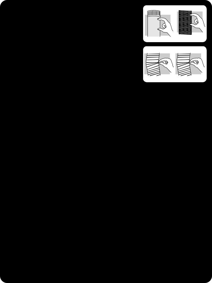
Exhaust duct must be four inches (10.2 cm) in diameter without obstructions. Rigid metal duct is recommended. Non-combustible semi-rigid flexible metal duct is acceptable.
DO NOT use plastic pipe, foil pipe, or flexible plastic pipe, because it contributes to poor drying performance and collects lint, which can lead to a fire hazard. To identify flexible foil or plastic duct, pinch the coils of the duct between your fingers. If the coils can be brought together, do not use the duct.
Use
Rigid Metal |
Semirigid Metal |
Do Not Use
Flexible Foil |
Plastic |
Maximum Exhaust Length
Rigid Metal Duct
Number of |
Weather Hood |
|
Weather Hood |
|
90° Elbows |
4-inch Opening |
|
21⁄2-inch Opening |
|
0 |
44 feet (13.4 m) |
|
34 feet (10.4 m) |
|
1 |
34 feet (10.4 m) |
|
26 feet (7.9 m) |
|
2 |
26 feet (7.9 m) |
|
20 feet (6.1 m) |
|
3 |
20 feet (6.1 m) |
|
14 feet (4.3 m) |
|
|
Flexible Metal Duct |
|
||
Number of |
Weather Hood |
|
|
Weather Hood |
90° Elbows |
4-inch Opening |
|
|
21⁄2-inch Opening |
0 |
24 feet (7.3 m) |
|
|
20 feet (6.1 m) |
1 |
20 feet (6.1 m) |
|
|
16 feet (4.9 m) |
2 |
16 feet (4.9 m) |
|
|
12 feet (3.7 m) |
3 |
12 feet (3.7 m) |
|
|
8 feet (2.4 m) |
Recommended Weather Hood |
Recommended for |
|
Short Runs Only |
||
|
 4" (10,16 cm)
 2-1/2" (6,35 cm)
4" (10,16 cm)
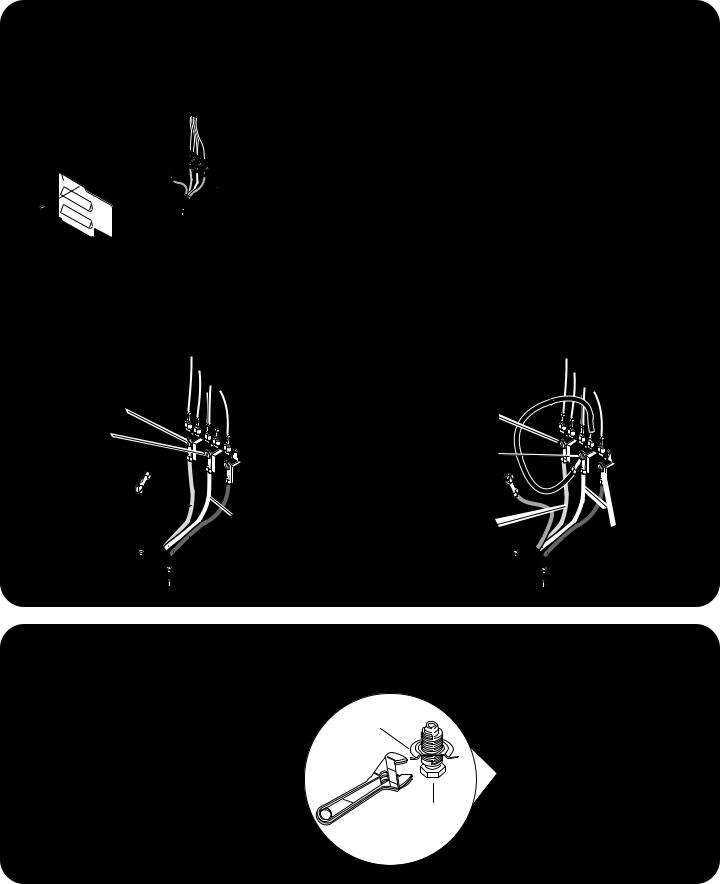
CONNECT 3ELECTRICAL
CORD
Access
cover
3-wire or 4-wire Plug Connection
Four-wire cord is required for mobile homes or where codes do not permit grounding through neutral.
1.Remove access cover from rear of dryer.
2.Use a strain relief and insert end of power cord through power supply hole.
3.Use the three screws from envelope located in the drum to attach the remaining power cord
•White wire to Neutral terminal.
•4-wire Plug Only—Remove ground screw and detach ground wire from bulkhead. Attach power cord ground (green) wire to rear bulkhead using ground screw. Attach free ground wire, previously attached with ground screw, with white wire to the neutral (center) terminal on the terminal block.
4.Tighten all screws and reinstall access cover removed in step 1.
3-wire Cord Installed |
4-wire Cord Installed |
"L1"
"L2"
Neutral
Ground screw
Red |
White |
|
Black |
POSITION AND
4LEVEL DRYER
Place dryer in position, adjust all legs (4) until dryer is level side to side and front to back.
Ground
Wire
"L1"
Neutral |
"L2" |
|
|
Ground |
|
screw |
|
Red |
White |
Green |
Black |
|
Level
Dryer
Base
Leveling
Leg
Important Safety Information
About Ground Wires
In the event of an electrical short circuit, a ground wire reduces the risk of electric shock by providing an escape wire for the electric current.
Standard accepted color coding for ground wires is green or green with a yellow stripe.
Grounding wires and wires colored like grounding wires are NOT to be used as current carrying conductors.
Grounding Instructions
This dryer must be connected to a grounded metal, permanent wiring system, or an equipment-grounding conductor must be run with the circuit conductors and connected to the equipment-grounding terminal or lead on the dryer.
•Power cord (pigtail) is not supplied with electric dryer. Type of pigtail and gauge of wire must conform to local codes and instructions.
Method of wiring dryer is optional and subject to local code requirements.
•Connect dryer to power supply with MAXIMUM RATED VOLTAGE listed on the nameplate.
•Use copper wire only. Shorter than 15' (4.5 m) use 10 A.W.G. Longer than 15' (4.5 m) use 8 A.W.G.
 WARNING
To reduce the risk of fire, the dryer MUST be exhausted to the outdoors. DO NOT exhaust dryer air into a window well, gas vent, chimney or enclosed, unventilated area, such as an attic, wall, ceiling, crawl space under a building or concealed space of a building.
 WARNING
To reduce the risk of fire, DO NOT use plastic pipe, foil pipe, or flexible plastic pipe to exhaust the dryer. Never install flexible duct in concealed spaces, such as a wall or ceiling.
 WARNING
To avoid risk of personal injury or death:
•Do not allow children to play on or in the appliance. Close supervision of children is necessary when the appliance is used near children.
 WARNING
To avoid risk of personal injury or death due to electrical shock:
•Observe all local codes and ordinances.
•Disconnect electrical power to unit before servicing.
•Ground appliance properly.
•Check with a qualified electrician if you are not sure this appliance is properly grounded.
•DO NOT ground to gas line.
•DO NOT ground to cold water pipe if pipe is interrupted by plastic, non-metallic gaskets or other insulating (non-conducting) materials.
•DO NOT modify plug on power cord. If plug does not fit electrical outlet, have proper outlet installed by qualified electrician.
•DO NOT have a fuse in the neutral or ground circuit. A fuse in the neutral or ground circuit could result in an electrical shock.
•DO NOT use an extension cord with this appliance.
•DO NOT use an adapter plug with this appliance.
•DO NOT pinch power cord.
 WARNING
To reduce the risk of fire, electric shock, serious injury or death, all wiring and grounding must conform with the latest edition of the National Electric Code, ANSI/NFPA 70, or the Canadian Electrical Code, CSA C22.1, and such local regulations as might apply. It is the customer’s responsibility to have the wiring and fuses checked by a qualified electrician to make sure your home has adequate electrical power to operate the dryer.
|
|
|
|
|
WARNING |
|
|
To avoid injury or death due to |
Save These Instructions |
||
|
|||
suffocation, remove door to |
|
||
dryer compartment before |
|
||
appliance is removed from |
|
||
service or discarded. |
|
||
|
|
|
|
4
Installation Requirements
Before You Install…
Consider |
Description |
|
|
|
|
Location |
Use dimensions shown in manual to determine space needed for installation. |
|
|
Place dryer on a solid floor in an area with an adequate air supply. A closet door |
|
|
must have a supply air vent of 80 sq. in. (517 sq. cm) minimum. |
|
|
Leveling legs can be adjusted from inside the dryer with a 1⁄4" driver. All four legs |
|
|
must rest firmly on the floor so the weight of the dryer is evenly distributed. The |
|
|
dryer must not rock. |
|
|
Dryer must not be installed or stored in an area where it will be exposed to water |
|
|
and/or weather. |
|
|
|
|
Electrical Requirements |
Dryer needs a 3- or 4-wire 120/240 volt, 30 amp, 60 hertz, 1 phase electrical supply. |
|
|
Refer to serial plate for specific requirements. Wiring diagram is located in control |
|
|
hood. |
|
|
|
|
Exhaust |
Use rigid or semi-rigid duct and exhaust the dryer to the outside by the shortest |
|
|
route possible. Failure to exhaust dryer properly will void warranty. |
|
|
• |
Dryer exhaust duct must be secured to the mobile home structure. Dryer exhaust |
|
|
MUST NOT terminate under the mobile home. |
|
• |
Exhaust duct must not be connected to any other duct, vent or chimney. |
|
• |
Venting materials are not supplied with the dryer (obtain locally). Do not use plas- |
|
|
tic or thin foil flexible ducting. |
|
• |
Static pressure in the dryer’s exhaust duct should be no greater than .6 inches |
|
|
(1.5 cm). Check with dryer running and no load. This can be measured with a |
|
|
manometer placed on the exhaust duct approximately two feet (61 cm) from the |
|
|
dryer. |
|
For the best exhaust system: |
|
|
• |
Locate dryer so exhaust duct is as short as possible. |
|
• |
Verify old ducts are cleaned before installing new dryer. |
|
• |
Use 4 inch (10.2 cm) diameter rigid or flexible metal duct. |
|
• |
Use duct tape on all joints. |
|
• |
Use as few elbows as possible. |
|
|
|
5

Dryer Dimensions and Minimum Clearances
|
|
<![if ! IE]> <![endif]>cm)(91,4*36" |
<![if ! IE]> <![endif]>cm) |
|
7.7" |
<![if ! IE]> <![endif]>(109,2*43" |
|
|
(19,6 cm) |
|
|
|
4.0" |
|
|
|
(10,2 cm) |
|
4.0" |
|
|
|
|
|
|
(10,2 cm) |
|
23.5" |
28" |
.4" |
26.9" |
(1,1 cm) |
|||
(59,7 cm) |
(71,1 cm) |
|
(68,3 cm) |
*With leveling legs turned fully into base
15.4" (39,1 cm)
FRONT VIEW |
SIDE VIEW |
FRONT VIEW |
(w/o Closet Door) |
|
(Closet Door) |
|
3" (7,6 cm) |
|
Closet |
|
Door |
12" |
2" (5,1 cm) |
(30,5 cm) |
|
|
Centered air |
|
openings minimum |
|
40 sq. in. |
|
(260 sq. cm) each |
0" |
12" |
|
(30,5 cm) |
||
(0 cm) |
||
Min. |
||
|
3" (7,6 cm)
0" (0 cm) |
0" (0 cm) |
2" (5,1 cm) |
Outer wall of |
|
|
|
enclosure |
6
 Loading...