


MDE16CS
Maytag MDE16CS, MDE21PD, MDE21PN, MDE16MN, MDE16PD User Manual
...
COMMERCIAL
GAS & ELECTRIC DRYERS
INSTALLATION INSTRUCTIONS
MODELS:
MDG21PN, MDG21PD, MDG16PD, MDG16MN, MDG16CS, MLG23PD,
MDE21PN, MDE21PD, MDE16PD, MDE16MN, MDE16CS, MLE23PD
SECADORAS COMERCIALES
DE GAS Y ELÉCTRICAS
INSTRUCCIONES DE INSTALACIÓN
MODELOS:
MDG21PN, MDG21PD, MDG16PD, MDG16MN, MDG16CS, MLG23PD,
MDE21PN, MDE21PD, MDE16PD, MDE16MN, MDE16CS, MLE23PD
ISTRUZIONI DI INSTALLAZIONE
DI ASCIUGA-BIANCHERIA
COMMERCIALI A GAS ED ELETTRICI
MODELLI:
MDG21PN, MDG21PD, MDG16PD, MDG16MN, MDG16CS, MLG23PD,
MDE21PN, MDE21PD, MDE16PD, MDE16MN, MDE16CS, MLE23PD
LEAVE THESE INSTRUCTIONS WITH THE OWNER
DEJE ESTAS INSTRUCCIONES CON EL PROPIETARIO
QUESTE ISTRUZIONI DEVONO ESSERE CONSERVATE DAL PROPRIETARIO
Printed in U.S.A. • Impreso en los Estados Unidos • Stampato negli Stati Uniti 2202408
Page 1
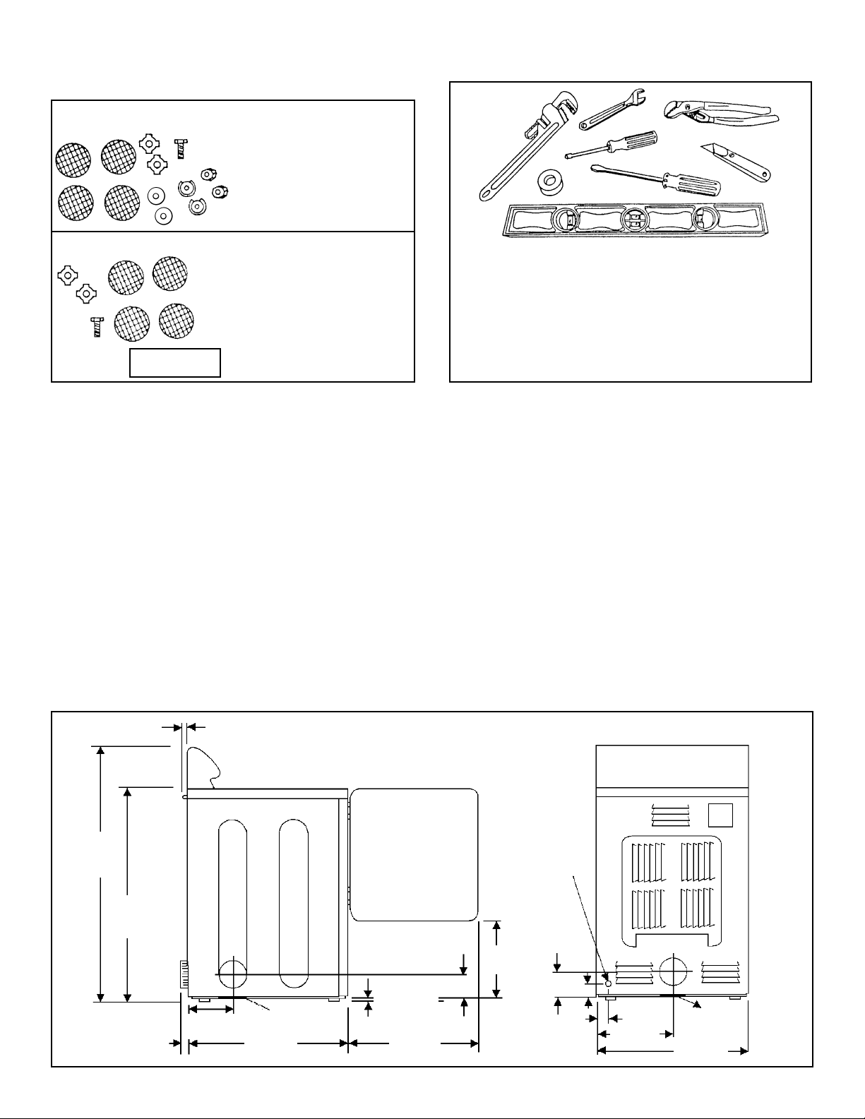
1. BEFORE YOU START
Typical tools needed for installation:
• PTFE tape • Spirit level
• Jointing compound • Screwdrivers
• Cutting knife • Duct tape
• Pipe wrench (heat resistant)
• Adjustable spanners • T20 security torx
screwdriver
WARNINGS:
Read these instructions carefully before you start, make sure you have everything necessary for proper
installation. These instructions cover both single and stacked pair dryers.
Proper installation is the responsibility of the owner. This appliance must be installed in accordance with
these Maytag Installation Instructions, and all local and national regulations, such as for electrical wiring,
municipal buildings and gas fittings. For Australia the installation should also be carried out in accordance
with the AGA Installation Code AG601 for gas burning appliances. Maytag gas dryers have been certified for
operation on either natural gas or LP gas (Australia: propane only) with appropriate conversion.
Service calls performed as a result of incorrect installation may be the responsibility of the installer.
These instructions should be left with the owner for future reference.
If disposing of an old dryer, remove the door to prevent it from being a hazard to young children.
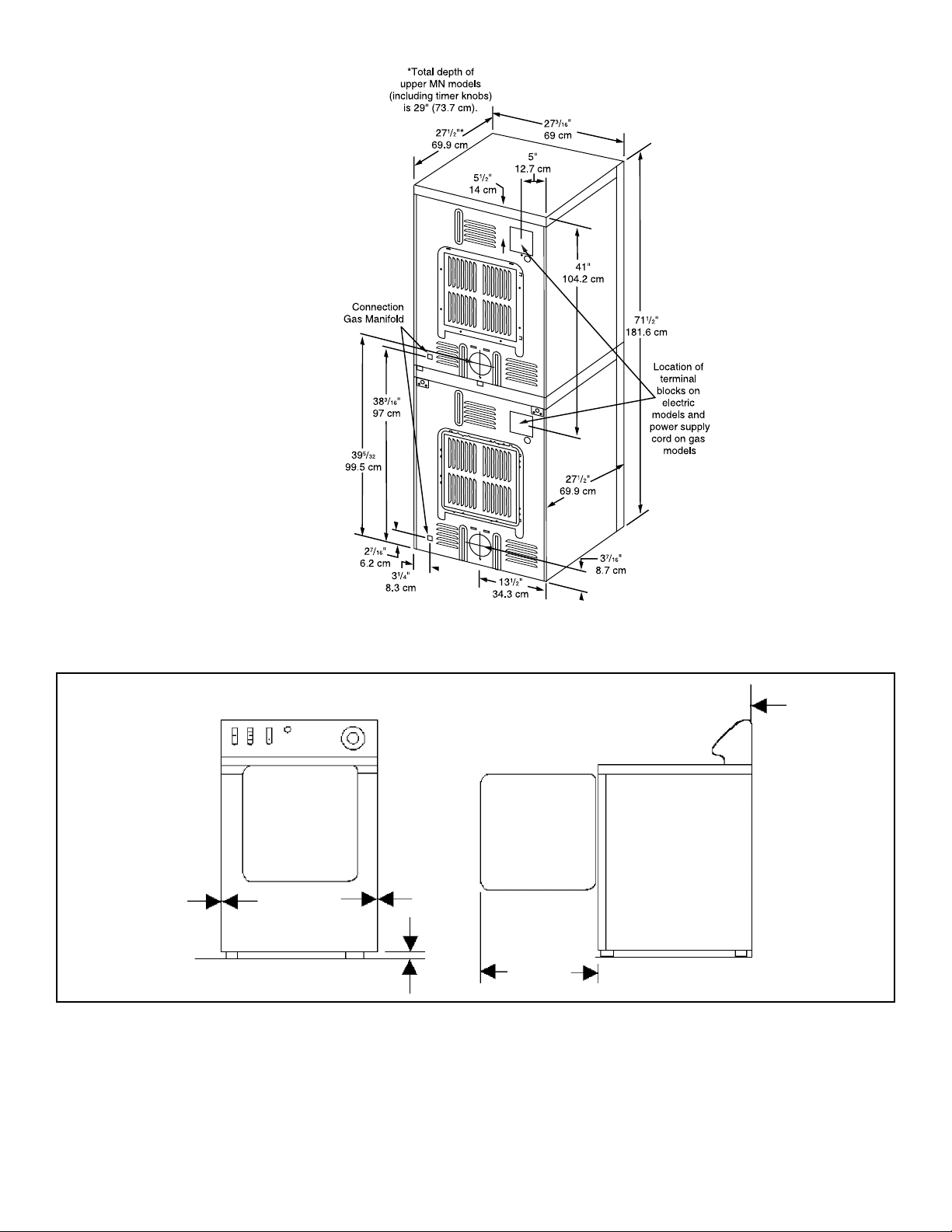
2. SPACE REQUIREMENTS
The dryer dimensions are shown in the following figures:
ITEMS PROVIDED
• 4 vinyl feet – MDE
and MDG models only
• Additional earth bond
screw and washers
• mains terminal nuts
and washers
• 4 vinyl feet – MDE and
MDG models only
• Additional earth bond
screw and washers
• Gas pipe adapter
Electric Dryer Only
Gas Dryer Only
1,9 cm
(3/4”)
3,8 cm (1 1/2”)
17,3 cm
(6 13/16”)
9,2 cm
(3 5/8”)
40,6 cm
(16”)
1 cm (3/8”)
minimum
Base
Exhaust
Base
Exhaust
Gas Pipe
56,6 cm
(22 1/4”)
69,8 cm
27 1/2”)
6,2 cm
(2 7/16”)
8,7 cm
(3 7/16”)
34,3 cm
(13 1/2”)
8,2 cm
(3 1/4”)
68,6 cm
(27”)
109,8 cm
(43 1/4”)
minimum
92,1 cm
(36 1/4”)
minimum
Gas Pipe
Adapter
Page 2
It is important to allow space around the dryer for adequate ventilation and exhausting. The minimum spacing
requirements are shown in the figure below:
0 cm
0 cm
56,5 cm
(22 1/4”)
1 cm Minimum
FRONT VIEW SIDE VIEW
0 cm
Page 3
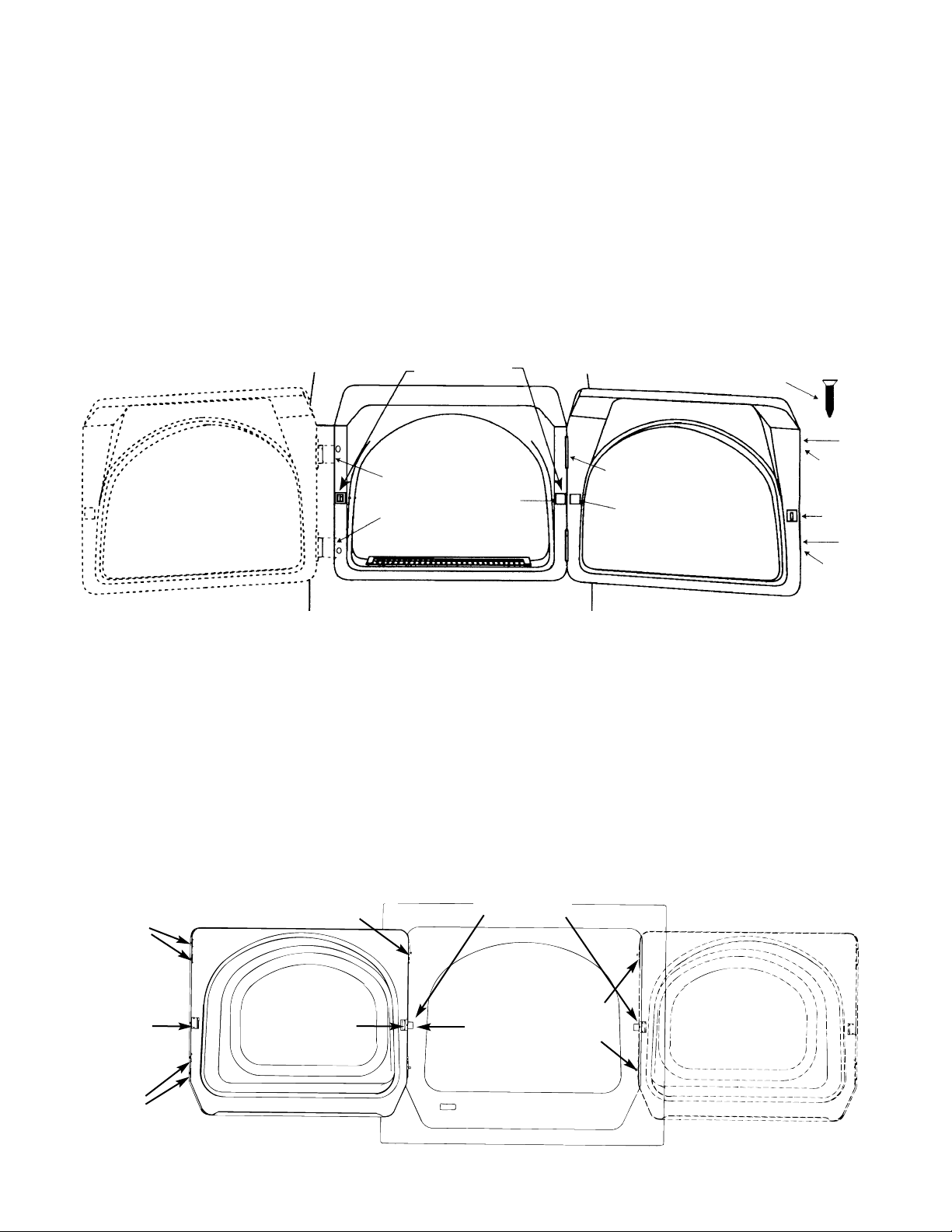
The direction of dryer door(s) can be reversed if desired.
For single model or lower dryer of stacked pair (see figure below):
1. Disconnect from electricity supply.
2. Remove the hinge hole covers and screws. Move the door catch cover to the opposite side.
3. While supporting the door remove 2 screws in the hinges that secure the hinges to the cabinet.
4. Remove the door by lifting slightly at the hinges and pulling the hinge tabs out of their slots.
5. Move the following parts to the opposite side of the door: 2 hinges and 4 hinge screws, 4 door screws,
door strike and screw, inner door cover plate and screw.
6. Attach the door to the opposite side of cabinet using the 2 countersunk hinge screws.
7. Tightening the lower hinge screw first will help to align the door and hinges.
8. Replace the hinge hole covers and screws in the opposite side.
For upper dryer of stacked pair (see figure below):
1. Remove the 2 hole plugs by gently prying out with a screwdriver. Pull the door catch cover off the door catch.
2. While supporting the door remove the 4 screws in the hinges that secure the hinges to the front panel.
3. Move the following parts to the opposite side of the door: 2 hinges and 4 hinge screws, 4 door screws,
door strike and screw, inner door cover plate and screw.
4. Attach the door to the opposite side of front panel using the 4 countersunk screws.
5. Tightening the lower hinge screw first will help to align the door and hinges.
6. Replace the 2 hole plugs in the opposite side of the front panel.
DOOR CATCH
HINGE
HOLE
COVER
DOOR
CATCH
COVER
DOOR
SCREWS
DOOR
SCREWS
DOOR
STRIKE
INNER DOOR
COVER PLATE
COUNTER
SUNK SCREW
HINGE
DOOR CATCH
HINGE
HOLE
COVER
DOOR
CATCH
COVER
DOOR
SCREWS
DOOR
SCREWS
DOOR
STRIKE
INNER DOOR
COVER PLATE
HINGE
It is important to make sure the room containing the appliance has an adequate air supply for gas combustion
and /or dryer operation. A window or equivalent means of ventilation must be opened in the room (an equivalent form of opening includes an adjustable louvre, hinged panel or other means of ventilation that opens
directly to outside air), providing a minimum cross-section open area of 464.6 sq. cm. (72 sq. in.) for each
dryer. There also has to be adequate ventilation to avoid the backflow of gases into the room from other appliances burning gaseous fuels, including any open fires, when operating this tumble dryer. If in doubt, consult
the other appliance manufacturers.
For gas dryer installations where dry cleaning machines are also installed, the sources of make-up air and air
movement to the dryers must be located away from the dry cleaners.
The dryer must not be installed or stored in an area where it will be exposed to water and/or weather. The
area must be kept clear and free of combustible materials, flammable vapors or liquids.
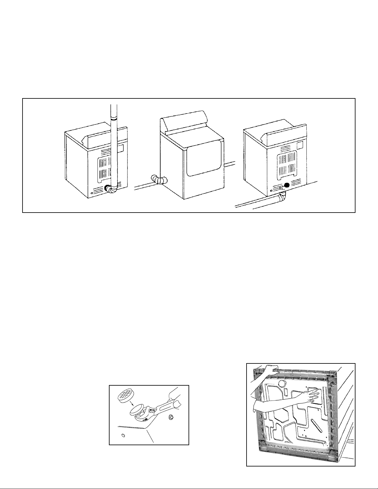
To remove dryer from transit base, lay two of the carton posts on the floor, and carefully tip the dryer forward
on its front to lay across the carton corner posts. Grasp plastic base and remove (see figure below).
Loosen the levelling feet lock nuts and attach the vinyl feet (see figure below). Place dryer in its intended
location and adjust feet until the top is level, before tightening lock nuts.
3. LOCATION
Each dryer should be located to permit adequate room in front for loading the clothes, and sufficient room
behind the dryer for the exhaust system.
This dryer is factory-ready for rear exhaust. To exhaust out the left side or the bottom, use the accessory
exhaust kit (see Commercial Installation Accessories). Instructions are included with the kit (see figure
below for alternative exhaust directions).
Page 4

USE A MINIMUM OF 100mm (4”) DIAMETER RIGID ALUMINUM OR RIGID GALVANIZED STEEL DUCT.
Do not use smaller duct. Ducts larger than 100mm can result in increased lint build-up. Any lint build-up
should be cleaned regularly. If flexible metal must be used in some areas, use the type with a stiff sheet
metal wall. Do not use flexible duct with a thin foil wall. Serious blockage can result if flexible metal duct is
bent too sharply. Never install any type of flexible duct in wall, ceilings or other concealed spaces.
Keep exhaust duct as straight and short as possible. Exhaust systems longer than recommended (see figure
below) can extend drying times, affect machine operation and may collect lint. Secure joints with proper duct
tape. Do not use screws.
DO NOT EXHAUST DRYER INTO ANY WALL,
CEILING, CRAWL SPACE OR OTHER CONCEALED
SPACE IN A BUILDING, GAS VENT OR CHIMNEY.
THIS COULD CREATE A FIRE HAZARD FROM LINT
EXPELLED BY THE DRYER.
The exhaust duct should end with an exhaust hood with
a swing-out flap to prevent back-draughts and access
for wildlife (see Commercial Installation Accessories).
Never use an exhaust hood with a magnetic flap. The
hood should have at least 300mm (12”) clearance
between the bottom of the hood and the ground or
other obstruction. The hood opening should point
down. Never install a screen over the exhaust outlet.
When possible, do not exhaust the dryer directly into a
basement window well in order to avoid a lint build-up.
Do not exhaust under a building. If exhaust ductwork
must run through an unheated area, the duct should be
insulated and slope slightly down towards the exhaust
hood to reduce condensation and lint build-up.
If an existing exhaust system is to be used with your
new dryer, you must ensure:
• The exhaust system meets all local and national regulations.
• That plastic flexible duct is not used.
• To completely inspect and clean all lint accumulation from the duct interior.
• The duct is not kinked or crushed which could restrict airflow.
• The exhaust hood flap opens and closes freely.
9 m
7 m
6 m
5 m
4 m
Exhaust Hood Type
Maximum length of 100mm (4”) diameter
rigid metal duct
Number
of
90° Tu rn s
0
1
2
3
4
30 m
24 m
20 m
15 m
11 m
18 m
15 m
12 m
9 m
7 m
100mm
64mm
Maximum length of 100mm (4”) diameter
flexible stiff walled metal duct
0
1
2
3
4
11 m
10 m
9 m
8 m
7 m
4. EXHAUSTING
Each dryer must be exhausted to the outside air. This is necessary for gas combustion (on gas models),
and will also prevent large amounts of moisture and some lint from being blown into the room.
Plastic or non-metal flexible duct presents a potential fire hazard. NEVER USE PLASTIC
OR NON-METAL FLEXIBLE DUCT. If your existing ductwork is plastic, non-metal or
combustible, replace it with metal. Plastic flexible duct can kink, sag, be punctured, reduce
airflow, extend drying times and affect dryer operation.
Page 5
WARNING
!
Page 6
If multiple units are exhausted into a common duct:
1. An exhaust cross-section area of 82cm
2
(12.6”2) is required per dryer. This will allow for free air movement
should all dryers be operated simultaneously.
2. A power exhaust may be used on multiple installations.
3. Ducts larger than 100mm (4”) diameter can result in increased lint accumulation. Such lint accumulation
should be cleaned regularly.
4. Exhaust ducting should be kept as short and direct as possible.
The operating pressure in any exhaust system must not exceed 23mm (0.92”) water gauge, or be less than 0.
This can be measured with the dryer(s) operating, by inserting a manometer connection at the point where
the exhaust duct connects to the dryer (a no-heat setting should be used, without clothes loaded and with a
clean lint filter).
Inspect and clean the interior of the exhaust system at least once a year. Disconnect from the electricity
supply prior to cleaning. Check the gas supply connection any time the dryer is moved. Frequently check to
be sure the exhaust hood flap opens and closes freely.
5. ELECTRICAL CONNECTION
WARNING: This is a 3-wire appliance which must be earthed.
Note: Single and stacked pair dryers are intended to be supplied by one electricity supply cord. The elec-
trical connection procedure is the same for both.
Each single and stacked pair gas dryer is fitted with an electrical supply cord and plug. It should be connected
to an electricity supply socket at the voltage shown on the dataplate. The minimum supply fuse capacity
should be 5A for single or 10A for stacked pair dryers. The dryer must be positioned so that the plug is
accessible. If the fitted plug is not used, the electrical connection must be carried out by a competent
electrician in accordance with local or national wiring regulations.
For Australia, each single electric dryer is fitted with a 20A cord and plug, and should be plugged into a suitable
electrical socket at the voltage shown on the dataplate.
Do not use extension lead assemblies on commercial installations.
If the supply cord is damaged, it must be replaced with a specially terminated cord by an authorized service
agent or a similarly qualified person in order to avoid a
hazard.
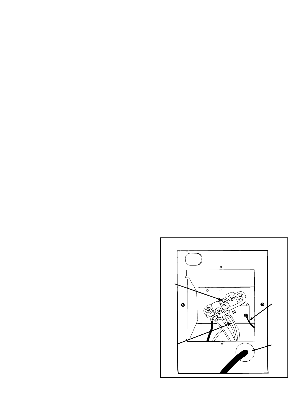
Each electric dryer for other countries is supplied without an electric cord and plug. They must be connected
to a single-phase electricity supply at the voltage shown
on the dataplate, by a suitable fixed wiring installation in
accordance with local and national wiring regulations. A
switch with a minimum contact separation of 3mm in
both poles must be incorporated into the fixed wiring for
dryer disconnection. A cord clamp bush is provided with
the dryer, and should be tightened on completion of
wiring. The electrical mains terminals are located
behind the small rear access panel, and connections
should be made as shown in the figure. Remember to
replace the terminal access panel.
Electric Single Dryer: A 3-wire circular cord of
minimum conductor size 2.5mm
2
cross-section area
should be used. A 30A supply fuse should be used.
Electric Dryer/Dryer: A 3-wire cable of minimum
conductor size 6.0mm
2
cross-section area should be
used. A 60A supply fuse should be used.
2-Wire and Ground System
Neutral
Post
Neutral
Power
Cord
Ground
Wire
Power
cord
and
strain
relief

Page 7
Note: In accordance with the European EMC Directive (89/336/EEC) the maximum
electricity supply system impedance to which the electric dryer should be connected is
declared to be 0.247Ω + j0.155Ω.
Some local wiring regulations require connection of an additional earth bond connection to
the dryer. If required, an additional earth bond wire and earth bond wire clamp are available (see Commercial Installation Accessories). The wire should be connected to the rear
panel of the dryer using the earth screw and washer as shown in the figure.
6. GAS CONNECTIONS
WARNING: The gas dryer is factory set with a burner orifice for natural gas supply (see Technical Specification). It
may be converted for use with LP butane or propane (Australia: propane only) gas using the correct conversion kit
(see Commercial Installation Accessories). Full instructions are supplied with the kit. Before installation, check that
the local distribution conditions, nature of gas and pressure, and the adjustment of the appliance are compatible.
Gas installation must be carried out in accordance with any local or national gas installation regulations by a
suitably qualified person.
Note: Single dryers are intended to be supplied by one gas supply line. Stacked pair dryers are intended to
be supplied by two gas supply lines, one to upper and one to lower dryer. The gas connection procedure is
the same for both. There is complete isolation internally between the two dryer gas systems, but before
undertaking any maintenance or servicing, both gas supplies must be disconnected.
Each dryer gas inlet connection is a 3/8” NPT thread. An adapter is supplied for conversion to ISO.7–1 thread. A
12.5mm (1/2”) gas supply line is recommended for each dryer. For multiple unit installations the size of the main
gas line must be adequate for the number of dryers (see Technical Specification for gas flow rate per dryer).
Gas connection to each dryer may be made by means of fixed pipe work or a flexible gas hose suitable for the
appliance and gas category. If flexible hose, a means of restraint should be used on the appliance to prevent
straining of the gas supply when the appliance is moved.
Remove the gas inlet connection thread protective cap. Apply joint compound or approximately 1-1/2 turns of
PTFE sealing tape over all threaded connections, and securely tighten. (Note: Jointing compound used must
be resistant to LPG.)
Check for leaks as directed by local or national regulations. DO NOT use a naked flame to check for gas
leaks. A pressure measurement tapping is provided on the gas valve within each dryer, accessible after
removal of the front panel. To remove this panel, remove 2 door fixing screws and opposite 2 fixing screws,
and for stacked pair the upper access panel.
Note: All gas dryers should be disconnected before any over-pressure testing of the gas supply system.
These gas dryers use an automatic ignition system to ignite the burners. There is no constant burning pilot light.
7. COMMERCIAL INSTALLATION ACCESSORIES
For all accessories and replacement parts contact your Maytag Commercial Distributor.
• Vent hood – 100mm (4”) opening . . . . . . . . . . . . . . . . . . . . . . . . . . . . . . . . . . . . . . . . . . . . . . . . . 059129
• Aluminum duct pipe – 100mm x 610mm (4” x 24”) . . . . . . . . . . . . . . . . . . . . . . . . . . . . . . . . . . . 059130
• Aluminum elbow – 100mm (4”) . . . . . . . . . . . . . . . . . . . . . . . . . . . . . . . . . . . . . . . . . . . . . . . . . . 059131
• Aluminum window plate – 381mm x 508mm (15” x 20”) with 100mm (4”) hole . . . . . . . . . . . . . . 059134
• Flexible aluminum duct – 100mm (4”) – 965mm (38”) extending to 2.44m (8’) . . . . . . . . . . . . . . 304353
• Clamp for flexible aluminum duct . . . . . . . . . . . . . . . . . . . . . . . . . . . . . . . . . . . . . . . . . . . . . . . . . 304630
• Exhaust duct kit for base and side exhausting . . . . . . . . . . . . . . . . . . . . . . . . . . . . . . . . . . . . . . . 12001453
(continued on page 8)
EARTH BOND
SCREW
(GROUND)
 Loading...