


 Loading...
RELEASE DEVICES
|
MADE IN THE U.S.A. |
MODELS A/B INSTALLATION MANUAL |
|
U.L. LISTED |
CANADIAN LISTED CSFM: 7300-1418:100 |
GENERAL DESCRIPTION: |
S/N:_______________ |
These Time Delay Release Devices are U.L. Listed, Canadian Listed, and CSFM Listed for use on rolling doors, single-slide and center parting level and inclined track doors. All models are normally energized Fail-Safe Releasing Devices incorporating state of the art electronic control circuitry. The devices respond to emergency conditions generated by manual or automatic normally closed initiating devices and shall be used in conjunction with a temperature fuse link system.
The device features include separate adjustable time delays for alarm and power loss, motor voltage sensing, form-C relay output, proximity/door edge input and trouble diagnostic capabilities. Models A and B can be wired for two or four wire configuration. *Check model label on unit to be installed to verify applicable features.
CAUTION: Review all installation instructions, procedures, cautions and warnings contained within this manual prior to installing and/or servicing this product. As with all releasing device systems, maximum fire protection is provided when installed in accordance with factory specifications and used with fuse link systems.
Fail-safe operation can only be provided with input power applied. DO NOT install this unit without fuse links.
TEST SYSTEM AT LEAST ONCE EVERY 90 DAYS TO ASSURE PROPER OPERATION.
RELEASE INSTALLATION INSTRUCTIONS - To be performed by factory authorized personnel only.
Installation and testing to factory specifications shall be performed by factory authorized personnel for proper operation in accordance with all of the latest National Fire Protection Association (NFPA), Underwriters Laboratories (UL), National Electrical Code (NEC), local, state, county, district and/or other applicable building and fire standards, guidelines, regulations and codes including, but not limited to, all appendices and amendments and the requirements of the local authority having jurisdiction (AHJ).
The following installation procedures must be followed to assure performance of the release device to factory standards.
SECTION A. MOUNTING PROCEDURE (Figure 3)
1.The release device shall be mounted on a vertical surface with chain end link exiting side of enclosure as illustrated in figure 3. The unit may be rotated 90 degrees CW for a direct vertical pull.
2.Release device enclosure shall be mounted with minimum #10 size fastening screws or bolts for securing to structures other than masonry. Masonry applications shall utilize 1/4" or greater anchors or studs as required to ensure proper mounting strength.
3.Release device and associated hardware [sash chain or 1/16 cable, eyebolts, fuse links (DO NOT install this unit without fuse links), turnbuckles] shall be installed as per door manufacturers recommendations (figure
3 typical installation configuration). Note should be taken that the end link direction of pull is perpendicular to the enclosure side. An eyebolt installed at a distance of 18 to 24 inches from the release device should
adequately redirect sash chain pull as illustrated in figure 3.
4.Complete hardware installation by connecting fuse links, sash chain, S-hooks and turnbuckles as required. Push resetlever in direction of arrow on label to allow insertion of end link through release device, side opening. Push end link completely in and release reset lever to latch end link. Remove sash chain slack by adjusting turnbuckle.
Do Not exceed 40 lbs. maximum pull rating on release device.
SECTION B. SMOKE DETECTORS
When installing smoke detectors with this unit refer to NFPA 72-1993 and NFPA 80, for instructions concerning proper placement and detection coverage.
End of line devices (relays) must be installed in accordance with U.L. 864. See electrical connections figure 4.
SECTION C. ELECTRICAL CONNECTIONS - All models (Figure 4)
Installation of all wiring and connections shall be performed in accordance with, but not limited to, the latest NFPA,U.L. and N.E.C. standards. In addition, all installations subject to Canadian standards shall be performed in accordance with the Canadian Electrical Code, Part I, with respect to wiring material, wiring gauge related to power capacity requirements and circuit length and wiring methods.
The following wiring instructions will configure the unit for independent delay on alarm and power loss. Four wires, two for input power and two for the initiating loop, are required. When installing this unit where only two wires are available, call tech support. This unit can accommodate a two wire installation.
1.Turn off power supply before beginning.
2.Verify voltage rating of release device to power source being utilized.
3.Connect power source inputs to TB3, screws 1 & 2. On 24vdc units observe proper polarity by placing positive (+) wire to screw 1. TB3 screw 3 shall be utilized for earth ground where applicable.
4.Normally closed initiating devices (smoke detectors)- remove jumper from screws 1 & 2 (Alarm loop will not function if jumper is not removed). Connect wiring from N/C initiating device alarm loop to TB1 screws 1 & 2 (see NFPA 72-1993 and NFPA 80 for proper placement of smoke detectors). NOTE: Alarm
loops cannot be series or parallel connected between TB1 of multiple release devices. Contact tech support for wiring instructions where multiple doors must close from a single initiating device.
2
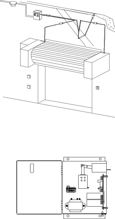
* TYPICAL INSTALLATION |
FIGURE 3 |
Ceiling
End link
Fuse link
RELEASE DEVICE |
Fuse link |
|
|
Sash chain or cable |
|
|
Thru wall conduit |
* Actual configuration may differ. This unit may be rotated 90 degrees CW for a vertical pull. See door manufacturer recommendations and NFPA 80 for use of this product with specific door. DO NOT install this unit without fuse links.
INSIDE VIEW LM90-AX & LM90-BX 120VAC |
FIG- |
URE 2 |
|
END LINK
TB2
TB3
TB1-1
LOGIC BOARD
* TRANSFORMER
* Transformer used on 120VAC models only.
3
SECTION C. ELECTRICAL CONNECTIONS - CONTINUED
OPTIONS: LM90-B-X only.
Motor voltage sensing
This option is used to detect the presence of operating voltage on motor driven units where closings are automated by a fire alarm signaling source, in conjunction with the operator. When motor control secondary voltage is present (24V-30V AC or dc) the release device logic will prevent the solenoid from energizing on alarm, thereby allowing the motor to drive the door closed, by activation from the automated fire alarm signaling source through the operator.
CAUTION: The automated signaling source and/or the motor operator shall contain logic capable of determining whether the door has fully closed upon activation. In absence of full closure, the motor control voltage shall be interrupted to release device allowing for release device initiated closure. CAUTION: DO NOT use this option on non-automated installations where door closings through the motor can only be initiated manually
*DOOR EDGE (Lower limit/Proximity switch)
This option interfaces to electrical contact type lower limit sensing devices and/or magnetic proximity type switches. If the electrical contact has toggled states from its N/O condition to a closed condition (TB1-5&6) indicating the door edge has made contact with desired down position, the release device logic will prevent the solenoid from energizing on alarm, thereby eliminating any damage which may result to the door from the release device attempting to close the already lowered door. This option only works as long as power is available to unit.
TROUBLE RELAY (TB1-8,9&10)
The trouble relay toggles immediately upon a power loss or alarm condition and may be used for turning on signalling appliances (horns,strobes,etc.) or other external signalling functions requiring a dry contact open or closure. Figure 4 illustrates contacts with no power to unit. With power applied TB1-9&10 are closed and toggle in alarm and power loss.
Verify that motor voltage is off before continuing.
5.Connect motor control sensing voltage (24vac) from motor controller transformer secondary to TB2 screws 1 & 2.
6.Normally open lower limit/proximity switch (closes in down limit). Connect wiring from *Aux. electrical loop toTB1 screws 5 & 6. Leave jumper in TB1-6&7. Remove jumper & use TB1-6&7 for a N/C
which opens in down limit.
*Note: Electrical loop must be provided as dry contacts and may not be used in conjunction with the simultaneous switching of a motor control or any other voltage through the same contacts.
Connections of this type will result in immediate damage to the release device.
Verify all connections made within unit. Close hinged cover and secure screw on lid after all connections are made.
DO NOT LEAVE COVER OPEN AFTER CONNECTIONS ARE MADE
4
Loading...