


CA-110
COLOR MONIT OR
SER VICE MANUAL
Website:http://biz.LGservice.com
E-mail:http://www.LGEservice.com/techsup.html
CAUTION
BEFORE SERVICING THE UNIT,
READ THE SAFETY PRECAUTIONS IN THIS MANUAL.
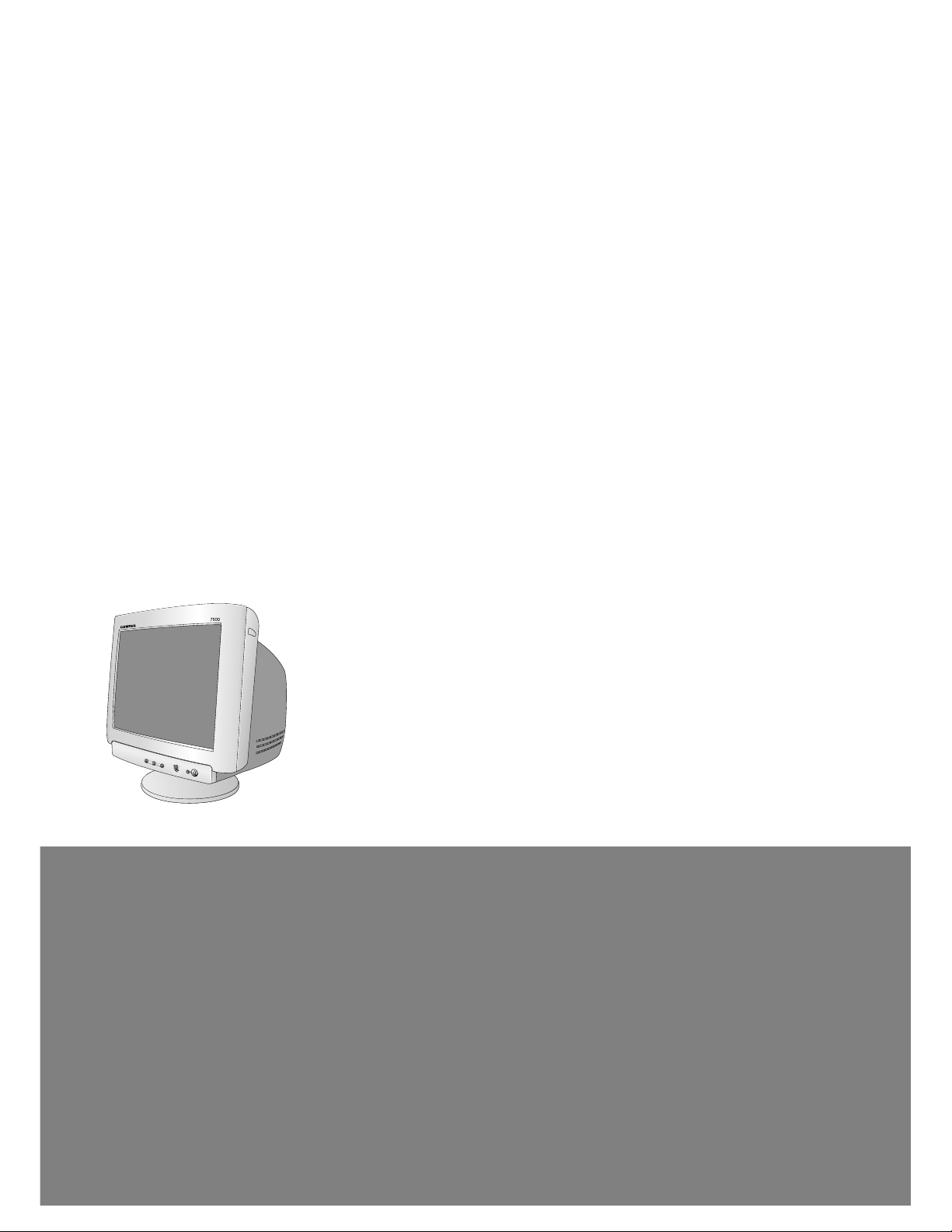
Coloreal
T
M
MODEL: S7500 (PE1165T), S7500 (PE1165),
MV7500 (PE1165U), MV7500 (PE1165),
CV7500 (PE1165U)
CHASSIS NO. : CA-1 10
F ACTORY MODEL: CQ771G
*( ) ID LABEL Model No.
1. PICTURE TUBE
Size : 17 inch
DefIection Angle : 90°
Neck Diameter : 29.1 mm
Dot Pitch : 0.28 mm
Face Treatment : Anti-Glare
Diagonal Inch : 16.06"
2. SIGNAL
2-1. Horizontal & Vertical Sync
1) Input Voltage Level: Low=0~1.2V, High=2.5~5.5V
2) Sync Polarity : Positive or Negative
2-2. Video Input Signal
1) Voltage Level : 0 ~ 0.7 Vp-p
a) Color 0, 0 : 0 Vp-p
b) Color 7, 0 : 0.467 Vp-p
c) Color 15, 0 : 0.7 Vp-p
2) Input Impedance : 75 Ω
3) Video Color : R, G, B Analog
4) Signal Format : Refer to the Timing Chart
2-3. Signal Connector
3 row 15-pin Connector (Attached)
2-4. Scanning Frequency
Horizontal : 30 ~ 70 kHz
Vertical : 50 ~ 140 Hz
3. POWER SUPPLY
3-1. Power Range
AC 100~240V , 50/60Hz, 2.0A
3-2. Power Consumption
4. DISPLAY AREA
4-1. Active Video Area :
• Max Image Size - 326.7 x 245.5 mm (12.86" x 9.67")
• Preset Image Size - 312 x 234 mm (12.28" x 9.21")
4-2. Display Color : Full Colors
4-3. Display Resolution : 1280 x 1024 / 60Hz
(Non-Interlace)
4-4. Video Bandwidth : 110 MHz
5. ENVIRONMENT
5-1. Operating Temperature: 10°C ~ 35°C (50°F ~ 95°F)
(Ambient)
5-2. Relative Humidity : 8%~ 80%
(Non-condensing)
5-3. Altitude : 5,000 m
6. DIMENSIONS (with TILT/SWIVEL)
Width : 404.0 mm (15.90 inch)
Depth : 438.5 mm (17.26 inch)
Height : 426.0 mm (16.77 inch)
7. WEIGHT (with TILT/SWIVEL)
Net Weight : 15.1 kg (33.29 lbs.)
Gross Weight : 17.8 kg (39.24 lbs.)
CONTENTS
- 2 -
SPECIFICATIONS ................................................... 2
SAFETY PRECAUTIONS ........................................ 3
TIMING CHART ....................................................... 4
OPERATING INSTRUCTIONS ................................ 5
WIRING DIAGRAM ................................................. 6
BLOCK DIAGRAM ................................................... 7
DESCRIPTION OF BLOCK DIAGRAM.....................8
ADJUSTMENT ...................................................... 10
TROUBLESHOOTING GUIDE .............................. 12
EXPLODED VIEW...................................................22
REPLACEMENT PARTS LIST ............................... 24
PIN CONFIGURATION........................................... 29
PACKING AND ACCESSORIES............................ 31
SCHEMATIC DIAGRAM......................................... 32
PRINTED CIRCUIT BOARD................................... 34
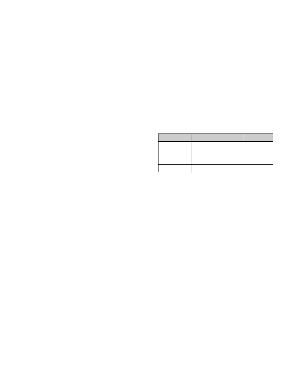
SPECIFICATIONS
MODE
FULL POWER
STAND-BY
SUSPEND
POWER OFF
POWER CONSUMPTION
less than 100 W
less than 5 W
less than 5 W
less than 5 W
LED COLOR
GREEN
AMBER
AMBER
OFF

SAFETY-RELATED COMPONENT WARNING!
There are special components used in this color monitor
which are important for safety. These parts are marked
on the schematic diagram and the replacement
parts list. It is essential that these critical parts should be
replaced with the manufacturer's specified parts to
prevent X-radiation, shock, fire, or other hazards. Do not
modify the original design without obtaining written
permission from manufacturer or you will void the original
parts and labor guarantee.
CAUTION:
No modification of any circuit should be
attempted.
Service work should be performed only after
you are thoroughly familiar with all of the
following safety checks and servicing
guidelines.
SAFETY CHECK
Care should be taken while servicing this color monitor
because of the high voltage used in the deflection circuits.
These voltages are exposed in such areas as the
associated flyback and yoke circuits.
FIRE & SHOCK HAZARD
An isolation transformer must be inserted between the
color monitor and AC power line before servicing the
chassis.
• In servicing, attention must be paid to the original lead
dress specially in the high voltage circuit. If a short
circuit is found, replace all parts which have been
overheated as a result of the short circuit.
• All the protective devices must be reinstalled per the
original design.
• Soldering must be inspected for the cold solder joints,
frayed leads, damaged insulation, solder splashes, or
the sharp points. Be sure to remove all foreign
materials.
IMPLOSION PROTECTION
All used display tubes are equipped with an integral
implosion protection system, but care should be taken to
avoid damage and scratching during installation. Use only
same type display tubes.
X-RADIATION
The only potential source of X-radiation is the picture tube.
However, when the high voltage circuitry is operating
properly there is no possibility of an X-radiation problem.
The basic precaution which must be exercised is keep the
high voltage at the factory recommended level; the normal
high voltage is about 25.5kV. The following steps describe
how to measure the high voltage and how to prevent Xradiation.
Note : It is important to use an accurate high voltage
meter calibrated periodically.
• To measure the high voltage, use a high impedance
high voltage meter, connect (–) to chassis and (+) to
the CDT anode cap.
• Set the brightness control to maximum point at full
white pattern.
• Measure the high voltage. The high voltage meter
should be indicated at the factory recommended level.
• If the meter indication exceeds the maximum level,
immediate service is required to prevent the possibility
of premature component failure.
• To prevent X-radiation possibility, it is essential to use
the specified picture tube.
CAUTION:
Please use only a plastic screwdriver to protect yourself
from shock hazard during service operation.
SAFETY PRECAUTIONS
- 3 -
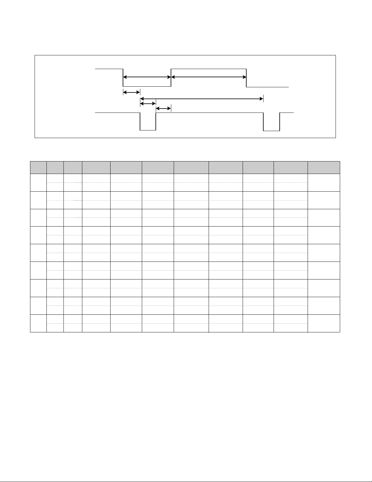
TIMING CHART
- 4 -
VIDEO
SYNC
C
E
D
F
AB
H – 37.500 26.667 20.317 6.349 2.032 3.810 0.508
V – 75.000 13.333 12.800 0.533 0.080 0.427 0.027
H – 31.469 31.778 25.422 6.356 3.813 1.907 0.636
V – 59.940 16.683 15.253 1.430 0.064 1.048 0.318
H – 43.269 23.112 17.778 5.334 1.556 2.222 1.556
V – 85.008 11.764 11.093 0.671 0.069 0.579 0.023
H – 31.470 31.778 25.422 6.356 3.813 1.907 0.636
V + 70.080 14.269 12.711 1.558 0.064 1.080 0.414
H + 46.880 21.330 16.160 5.170 1.620 3.230 0.320
V + 75.010 13.331 12.798 0.533 0.064 0.448 0.021
H + 53.674 18.631 14.222 4.409 1.138 2.702 0.569
V + 85.061 11.756 11.178 0.578 0.056 0.503 0.019
H + 60.023 16.660 13.003 3.657 1.219 2.235 0.203
V + 75.029 13.328 12.795 0.533 0.050 0.466 0.017
H + 68.677 14.561 10.836 3.725 1.061 2.201 0.508
V + 84.997 11.765 11.183 0.582 0.044 0.523 0.015
H + 63.98 15.63 11.85 3.78 1.04 2.30 0.44
V + 60.02 16.661 16.005 0.656 0.047 0.594 0.015
Mode
H/V
Sort
1
2
3
4
5
6
7
8
9
<< Dot Clock (MHz), Horizontal Frequency (kHz), Vertical Frequency (Hz), Horizontal etc... (µs), Vertical etc... (ms) >>
Sync
Polarity
Frequency
Total Period
(E)
Video Active
Time (A)
Sync Duration
(D)
Blanking Time
(B)
Back Porch
(F)
Front Porch
(C)
640x480
75Hz
640x480
85Hz
720x400
70Hz
800x600
75Hz
800x600
85Hz
1024x768
75Hz
1024x768
85Hz
1280x1024
60Hz
640x480
60Hz
Resolution

- 5 -
OPERATING INSTRUCTIONS
C
o
l
o
r
e
a
l
T
M
FRONT VIEW REAR VIEW
AC Power Socket
Signal Connector
See Front Control Panel
Front Control Panel
1. Power/LED
Controls power to the monitor.
The LED on the power button is illuminated when the
power is on.
2. Right Adjustment
Moves clockwise through menu options or increases
adjustment levels.
3. Left Adjustment
M
oves counter-clockwise through menu options or
decreases adjustment levels.
4. Select
Launches on-screen displays, selects functions and
adjustments, and exits menus and On-Screen Display.
5. Hot Key
Left Adjustment
Just select left adjustment key without OSD display.
Contrast menu display.
Right adjuatment
Just select right adjustment key with OSD display.
Brightness menu display.
Power ON/OFF Button
2
3
4
1
Coloreal
T
M
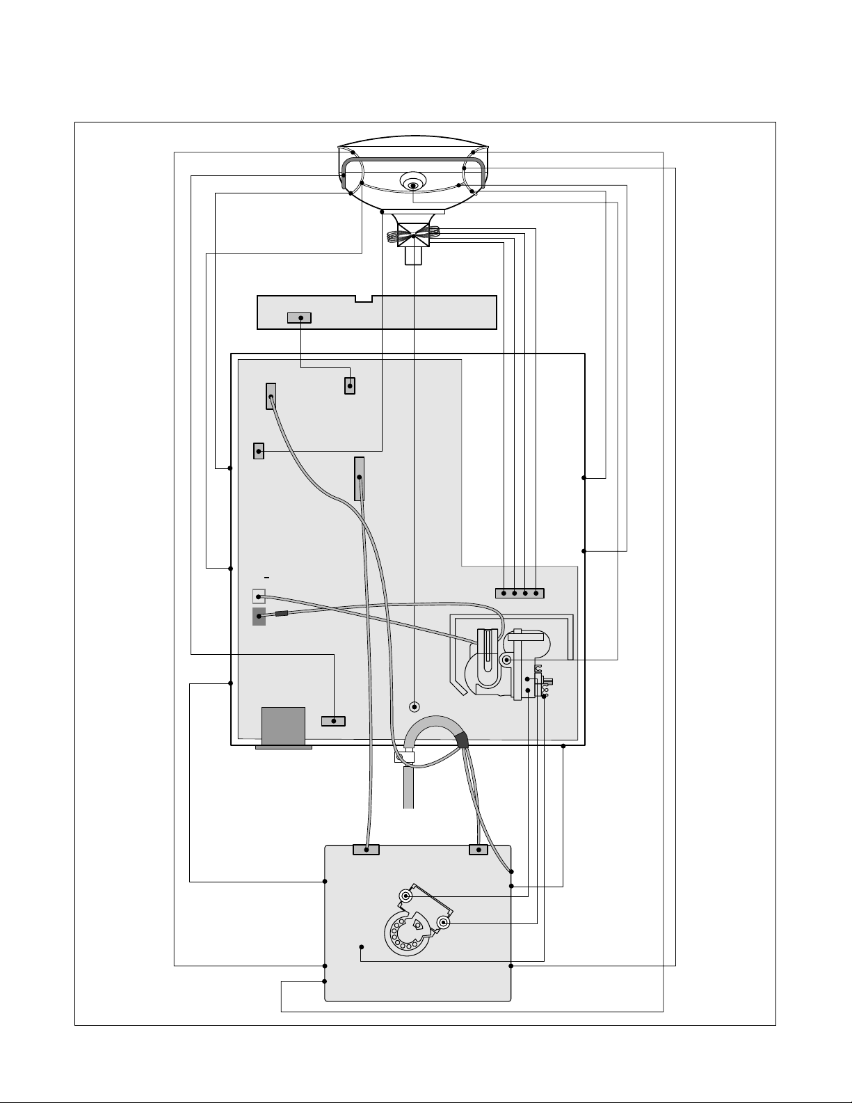
WIRING DIAGRAM
- 6 -
P501
P201
P405
P301
P302
P303
P702
P701
T1
P402
P902
S
+
S
Signal
Cable
AC
Socket
FBT
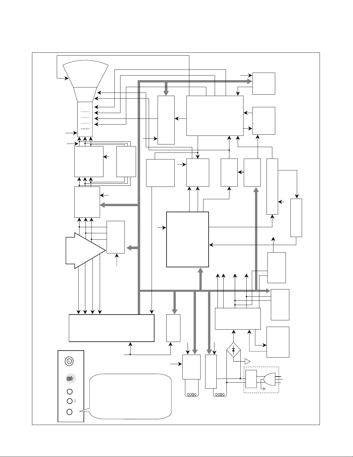
BLOCK DIAGRAM
- 7 -
MENU
POWER
POWER INPUT
100~240VAC
(50/60Hz)
Line
Filter
Degaussing
Circuit
< OSD Control >
SMPS
TRANS
(T901)
SMPS
CONTROL
(IC901)
DPM
CONTROL
CIRCUIT
Voltage
Regulating
Circuit
80V
50V 15V
6.3V
TILT
Control
Circuit
6.3V
15V
E
2
PROM
(IC402)
H POSITION
BRIGHTNESS
CONTRAST
H SIZE
V POSITION
V SIZE
SPCC
TRAPEZOID
PIN BALANCE
PARALLELOGRAM
ROTATION
DEGAUSS
COLOR TEMPERADURE
FACTORY RECALL
EXIT
5V
OSD IC
(IC301)
NT6872
H-Sync Sig
V-Sync Sig
I
2
C DATA(SDA)
I
2
C CLOCK(SCL)
VIDEO
LM1269
PRE-AMP
(IC302)
Signal
Cable
R
G
B
VIDEO
LM2467
LM2480
CUT OFF IC
(IC304)
MAIN AMP
(IC303)
5V
5V
H/V Sync Processor
( IC701 )
TDA4857
V-OUT
( IC601)
TDA4866
H-OUT
( Q706)
H-Linearity
Correction
DC/DC Converter
X-RAY
Protection
Circuit
FBT
( T701 )
Dynamic
Focus
Circuit
Auto
Beam
Limit
Vertical Blanking,
Brightness Control
- 160V
40V
400V
STEP UP
15V
D/D Feed Back
15V
MICOM
(IC401)
SCL / SDA
H/V Sync,
PWM Control
15V
5V
15V
80V
15V
50V
DY CDT
Heater ( 6.3V )
I
2
C
I
2
C
I
2
C
H/V
Sync
G
1
Screen(G2)
Dynamic Focus
Static Focus
H.V
R/G/B
Drive/Contrast
Cut-Off
H-DRV
B-DRV
B+
15V
TILT
COIL
DEGAUSSING
COIL
I
2
C
Vout 1
Vout 2
+
C
o
lo
re
a
l
T
M

DESCRIPTION OF BLOCK DIAGRAM
- 8 -
1. Line Filter & Associated Circuit.
This is used for suppressing noise of power input line
flowing into the monitor and/or some noise generated in
this monitor flowing out through the power input line.
That is to say, this circuit prevents interference between
the monitor and other electric appliances.
2. Degauss Circuit & Coil.
The degauss circuit consists of the degaussing coil, the
PTC(Positive Temperature Coefficient) thermistor(TH901),
and the relay(RL901). This circuit eliminates abnormal
color of the screen automatically by degaussing the
shadow mask in the CRT during turning on the power
switch. When you need to degauss in using the monitor,
select DEGAUSS on the OSD menu.
3. SMPS(Switching Mode Power Supply).
This circuit is working of 90~264V AC(50/60Hz).
The operation procedure is as follows:
1) AC input voltage is rectified and smoothed by the bridge
diodes (D900) and the capacitor (C908).
2) The rectified voltage(DC) is applied to the primary coil
of the transformer(T901).
3) The control IC(IC901) generates switching pulse to turn
on and off the primary coil of the transformer (T901)
repeatedly.
4) Depending on turn ratio of the transformer, the
secondary voltages appear at the secondary coils of the
transformer(T901).
5) These secondary voltages are rectified by each
diode(D941, D942, D951, D961, D962, D971) and operate
other circuit. (horizontal and vertical deflection, video
amplifier, ...etc.)
4. Display Power Management Circuit.
This circuit control power consumption of the monitor by
detecting H and V sync signal. There are off mode. When no
horizontal or vertical sync signal input, the circuit consists of
Q941 and Q951 becomes off mode. It’s power consumption
is below 5W.
5. X-ray Protection.
If the high voltage of the FBT reaches up to 29kV (abnormal
state), IC401(MICOM) pin 35 Sensing from FBT directly.
Then MICOM control IC701 (Deflection controller) to stop
Horizontal drive pulse and stop Horizontal Deflection.
6. Micom(Microprocessor) Circuit.
The operating procedure of Micom(Microprocessor) and
its associated circuit is as follows:
1) H and V sync signal is supplied from the signal cable.
2) The Micom(IC401) distinguishes polarity and
frequency of H and V sync.
3) The Micom sets operating mode and offers the
controlled data. (H-size, H-position, V-size, ... etc.)
4) The controlled data of each mode is stored in itself.
5) User can adjust screen condition by each OSD
function. The data of the adjusted condition is stored
in EEPROM(IC402).
7. Horizontal and Vertical Synchronous Processor.
This circuit generates the horizontal drive pulse and the
vertical drive pulse by taking sync-signal from the SignalCable. This circuit consists of the TDA4857(IC701) and
the associated circuit.
8. D/D(DC to DC) Converter.
This circuit supplies DC voltage to the horizontal deflection
output circuit by increasing DC 50V which is the
secondary voltage of the SMPS in accordance with the
input horizontal sync signal.
9. Side-Pincushion & Trapezoid Correction Cirucit.
This circuit improves the side-pincushion and the
trapezoid distortion of the screen by mixing parabola and
saw-tooth wave to output of the horizontal deflection D/D
converter which is used for the supply voltage(B + ) of the
deflection circuit.
10. Horizontal Deflection Output Circuit.
This circuit makes the horizontal deflection by supplying
the saw-tooth current to the horizontal deflection yoke.
11. High Voltage Output & FBT(Flyback Transformer).
The high voltage output circuit is used for generating pulse
wave to the primary coil of the FBT(Flyback Transformer) .
A boosted voltage(about 25.5KV) appears at the
secondary of the FBT and it is supplied to the anode of the
CDT. And there are another output voltages such as the
dynamic focus and the screen voltage(G2).
12. H-Linearity Correction Circuit.
This circuit corrects the horizontal linearity for each
horizontal sync frequency.
13. Vertical Output Circuit.
This circuit takes the vertical ramp wave from the
TDA4857(IC701) and performs the vertical deflection by
supplying the saw-tooth current from the TDA4866(IC601)
to the vertical deflection yoke.
14. Dynamic Focus Output Circuit.
This circuit takes the horizontal and the vertical parabola
waves from the TDA4857(IC701) and amplifies it to
maintain constant focus on center and corners in the
screen.

- 9 -
15. H& V Blanking and Brightness Control.
Blanking circuit eliminates retrace line by supplying
negative pulse to the G1 of the CRT. And Brightness
circuit is used for control of the screen brightness.
16. Image Rotation (Tilt) Circuit.
This circuit corrects the tilt of the screen by supplying the
image rotation signal to the tilt coil which is attached near
the deflection yoke of the CRT.
17. OSD Circuit
This circuit is used for performing the OSD(On-ScreenDisplay) function.
When a user selects the OSD Select/Adjustment control,
the adjustment status displays on the screen.
18. Video Pre-Amp Circuit.
This circuit amplifies the analog video signal from 0-0.7V
to 0-4V. It is operated by taking the clamp, R, G, B drive
and contrast signal from the Micom(IC401).
19. Video Output Amp Circuit.
This circuit amplifies the video signal which comes from
the video pre-amp circuit and amplified it to applied the
CRT cathode.

- 10 -
ADJUSTMENT
GENERAL INFORMATION
All adjustment are thoroughly checked and corrected
when the monitor leaves the factory, but sometimes
several adjustments may be required.
Adjustment should be following procedure and after
warming up for a minimum of 30 minutes.
• Alignment appliances and tools.
- IBM compatible PC.
- Programmable Signal Generator.
(eg. VG-819 made by Astrodesign Co.)
- EPROM or EEPROM with saved each mode data.
- Alignment Adaptor and Software.
- Digital Voltmeter.
- White Balance Meter.
- Luminance Meter.
- High-voltage Meter.
AUTOMATIC AND MANUAL DEGAUSSING
The degaussing coil is mounted around the CDT so that
automatic degaussing when turn on the monitor. But a
monitor is moved or faced in a different direction, become
poor color purity cause of CDT magnetized, then
press
DEGAUSS on the OSD menu.
ADJUSTMENT PROCEDURE & METHOD
-Install the cable for adjustment such as Figure 1and run
the alignment program on the DOS for IBM compatible PC.
-Set external Brightness and Contrast volume to max position.
1. Adjustment for B+ Voltage.
1) Display cross hatch pattern at Mode 8.
2) Check C999 (+) voltage to 50± 0.5Vdc.
2. Adjustment for High-Voltage.
1) Display cross hatch pattern at Mode 8.
2) DIST.ADJ→CTRL PWM → High Voltage Command.
3) Adjust High Voltage to 25.5kV
±
0.3 kVdc.
4) Press Enter Key.
3. Adjustment for Factory Mode (Preset Mode).
1) Display cross hatch pattern at Mode 1.
2) Run alignment program for CQ771G on the IBM
compatible PC.
3) EEPROM → ALL CLEAR → Y(Yes) command.
<Caution> Do not run this procedure unless the
EEPROM is changed. All data in EEPROM (mode
data and color data) will be erased.
4) Power button of the monitor turn off → turn on.
5) COMMAND→PRESET START→Y(Yes) command.
6) DIST. ADJ. → CTRL PWM → TILT command.
7) Adjust tilt as arrow keys to be the best condition.
8) DIST. ADJ. → BALANCE command.
9) Adjust parallelogram as arrow keys to be the best
condition.
10)
Adjust balance of pin-balance as arrow keys to be
the best condition.
11)
DIST. ADJ. → FOS. ADJ command.
12)
Adjust V-SIZE as arrow keys to 234±2mm.
13)
Adjust V-POSITION as arrow keys to center of the
screen.
14)
Adjust H-SIZE as arrow keys to 312±2mm.
15)
Adjust H-POSITION as arrow keys to center of the
screen.
16)
Adjust S-PCC (Side-Pincushion) as arrow keys to be
the best condition.
17)
Adjust TRAPEZOID as arrow keys to be the best
condition.
18)
Save of the Mode 1.
19)
Display from Mode 1 to 8 and repeat above from
number 12) to 19)
20)
PRESET EXIT → Y (Yes) command.
4. Adjustment for White Balance and Luminance.
1) Set the White Balance Meter.
2) Press the DEGAUSS on the OSD menu for
demagnetization of the CDT.
3) COLOR ADJ. → LUMINANCE command of the
alignment program.
4) Set Brightness and Contrast to Max position.
5) Display color 0,0 pattern at Mode 8.
6) COLOR ADJ.→ BIAS ADJ.→ COLOR No. → 1
command of the alignment program.
7) Check whether green color or not at R-BIAS and GBIAS to min position and B-BIAS to 127(7F) and
Sub-Brightness to 177(B1) position. Adjust G2
(screen) command to 0.4
±
0.05FL of the raster
luminance.
8) Adjust R-BIAS and G-BIAS command to x=0.283
±
0.005 and y=0.298
±
0.005 on the White Balance
Meter with PC arrow keys.
9)
Adjust SUB-Brightnesscommand to 0.5±0.1FL of the
raster luminance.
10)
Adjust repeat number 8).
11)
After push the “ENTER” key.
11-1)
COMMAND → PRESET START → Y(Yes) command.
12)
Display color 15,0 full white pattern at Mode 8.
13)
DRIVE ADJ.→ No 1. command.

- 11 -
14)
Set Brightness is cut-off(0.06FL) and Contrast to
Max position.
15)
Set SUB-CONTRAST Max 127(7F) (decimal) position.
16)
Set B-DRIVE to 90(5A); LG CDT at DRIVE of the
alignment program.
(TECO CDT: B-DRIVE 100(64))
17-1)
Adjust R-DRIVE and G-DRIVE command to white
balance x=0.283
±
0.003 and y=0.298±0.003 at Full-
White on the White Balance Meter with PC arrow keys.
17-2)
Display color 15,0 window pattern 5Box 50x50mm at
mode 8.
18)
Adjust SUB-CONTRAST command to 50±1FL at
B/Raster 0.06FL.
19)
Display color 15,0 full white patten at Mode 8.
20)
Set Brightness and Contrast to Max position.
21)
COLOR ADJ. → LUMINANCE → ABL command.
22)
Adjust ABL to 33±1FL of the luminance at B/Raster 0.06FL.
23)
After push the “ENTER” key, and “COMMAND →
PRESET EXIT → Y(Yes)” command.
24)
Exit from the program.
5. Input EDID Data.
1) Display color 15,0 cross hatch pattern at Mode 8.
2) EEPROM → Write EDID command and confirm
“EDID Write OK!!” message of monitor.
3) Exit from the alignment program.
4) Power switch OFF/ON for EDID data save.
6. Adjustment for Focus.
1) Set the Brightness and Contrast to max position.
2) Display cross hatch with quadrant text pattern in full
screen at Mode 8.
3) Adjust two Focus control on the FBT that focus
should be the best condition.
 Loading...