


ELECTRIC & GAS DRYER
SERVICE MANUAL
CAUTION
READ THIS MANUAL CAREFULLY IN ORDER TO
PROPERLY DIAGNOSE PROBLEMS AND TO SAFELY
PROVIDE QUALITY SERVICE ON THESE DRYERS.
MODEL : CDE3379WD/CDG3389WD
CDE3379WN/CDG3389WN

NOV. 2006 PRINTED IN KOREA |
|
|
|
|
|
P/No.:3828EL3005K |
|
|
|
|
|
||
|
|
|
|
|
||
|
|
|
|
|
|
|
|
|
|
|
|
|
|
IMPORTANT SAFETY NOTICE
The information in this service guide is intended for use by individuals possessing skill and experience in electrical, electronic, and mechanical appliance repair. Any attempt to repair a major appliance may result in personal injury and property damage. The manufacturer or seller cannot be responsible for the interpretation of this information, nor can it assume any liability in connection with its use.
! WARNING
To avoid personal injury, disconnect power before servicing this product. If electrical power is required for diagnosis or test purposes, disconnect the power immediately after performing the necessary checks.
RECONNECT ALL GROUNDING DEVICES
If grounding wires, screws, straps, clips, nuts, or washers used to complete a path to ground are removed for service, they must be returned to their original position and properly fastened.
WHAT TO DO IF YOU SMELL GAS:
■Do not try to light a match, or cigarette, or turn on any gas or electrical appliance.
■Do not touch any electrical switches. Do not use any phone in your building.
■Clear the room, building or area of all occupants.
■Immediately call your gas supplier from a neighbor’s phone. Follow the gas supplier’s instructions carefully.
■If you cannot reach your gas supplier, call the fire department.
IMPORTANT
Electrostatic Discharge (ESD)
Sensitive Electronics
ESD problems are present everywhere. ESD may damage or weaken the electronic control assembly. The new control assembly may appear to work well after repair is finished, but failure may occur at a later date due to ESD stress.
■Use an anti-static wrist strap. Connect wrist strap to green ground connection point or unpainted metal in the appliance.
-OR -
Touch your finger repeatedly to a green ground connection point or unpainted metal in the appliance.
■Before removing the part from its package, touch the anti-static bag to a green ground connection point or unpainted metal in the appliance.
■Avoid touching electronic parts or terminal contacts. Handle electronic control assembly by edges only.
■Observe above instructions when repackaging failed electronic control assembly in an anti-static bag.
2

|
CONTENTS |
|
1. |
IMPORTANT SAFETY INSTRUCTIONS.................................................................................................................. |
4 |
2. |
SPECIFICATIONS ............................................................................................................................................. |
10 |
3. |
FEATURES AND BENEFITS ............................................................................................................................... |
12 |
4. |
INITIAL STEPS FOR INSTALLING YOUR DRYER ................................................................................................... |
13 |
5. |
INSTALLATION INSTRUCTIONS ........................................................................................................................ |
18 |
6. |
ELECTRICAL REQUIREMENTS FOR ELECTRIC DRYERS ......................................................................................... |
20 |
7. |
ELECTRICAL REQUIREMENTS FOR GAS DRYERS ................................................................................................ |
25 |
8. GAS REQUIREMENTS AND INSTRUCTIONS ...................................................................................................... |
26 |
|
9. EXHAUST REQUIREMENTS AND MAINTENANCE.............................................................................................. |
27 |
|
10. DRYER CYCLE PROCESS ................................................................................................................................ |
29 |
|
11. COMPONENT TESTING INFORMATION ......................................................................................................... |
30 |
|
12. MOTOR DIAGRAM AND SCHEMATIC ............................................................................................................ |
33 |
|
13. CONTROL LAYOUT ....................................................................................................................................... |
34 |
|
14. WIRING DIAGRAM ....................................................................................................................................... |
35 |
|
15. DIAGNOSTIC TEST......................................................................................................................................... |
36 |
|
|
15-1. TEST 1 120VAC ELECTRICAL SUPPLY ................................................................................................... |
37 |
|
15-2. TEST 2 THERMISTOR TEST ................................................................................................................... |
40 |
|
15-3. TEST 3 MOTOR TEST .......................................................................................................................... |
41 |
|
15-4. TEST 4 MOISTURE SENSOR ............................................................................................................... |
42 |
|
15-5. TEST 5 DOOR SWITCH TEST .............................................................................................................. |
43 |
|
15-6. TEST 6 HEATER SWITCH TEST - ELECTRIC MODEL ................................................................................ |
44 |
|
15-7. TEST 7 GAS VALVE TEST - GAS MODEL .............................................................................................. |
45 |
|
15-8. TEST 8 SEMI CONDUCTOR ................................................................................................................. |
46 |
16. CHANGE GAS SETTING (NATURAL GAS, PROPANE GAS) ............................................................................ |
47 |
|
17. DISASSEMBLY INSTRUCTIONS ....................................................................................................................... |
49 |
|
18. EXPLODED VIEW ........................................................................................................................................... |
56 |
|
|
18-1. CONTROL PANEL & PLATE ASSEMBLY................................................................................................... |
56 |
|
18-2. CABINET & DOOR ASSEMBLY............................................................................................................... |
57 |
|
18-3-1. DRUM & MOTOR ASSEMBLY: ELECTRIC MODEL ................................................................................. |
58 |
|
18-3-2. DRUM & MOTOR ASSEMBLY: GAS MODEL ........................................................................................ |
59 |
19. REPLACEMENT PARTS LIST.............................................................................................................................. |
60 |
|
20. MAINTENANCE............................................................................................................................................. |
64 |
|
21. TROUBLESHOOTING GUIDE........................................................................................................................... |
65 |
|
3
1 IMPORTANT SAFETY INSTRUCTIONS
READ ALL INSTRUCTIONS BEFORE USE
! WARNING For your safety, the information in this manual must be followed to minimize the risk of fire or explosion, electric shock, or to prevent property damage, personal injury, or loss of life.
Your Safety and the safety of others are very important.
We have provided many important safety messages in this manual and on your appliance. Always read and obey all safety messages.
This is the safety alert symbol.
!This symbol alerts you to potential hazards that can kill or hurt you and others.
All safety messages will follow the safety alert symbol and either the word DANGER or WARNING. These words mean:
!DANGER You can be killed or seriously injured if you don’t Immediately follow instructions.
!WARNING You can be killed or seriously injured if you don’t follow instructions.
All safety messages will tell you what the potential hazard is, tell you how the reduce the chance of injury, and tell you what can happen if the instructions are not followed.
BASIC SAFETY PRECAUTIONS
! WARNING To reduce the risk of fire, electric shock, or injury to persons when using your appliance, follow basic precautions, including the following:
•Read all instructions before using the dryer.
•Before use, the dryer must be properly installed as described in this manual.
•Do not place items exposed to cooking oils in your dryer. Items contaminated with cooking oils may contribute to a chemical reaction that could cause a load to catch fire.
Do not dry articles that have been previously cleaned in, washed in, soaked in, or spotted with gasoline, drycleaning solvents, other flammable or explosive substances as they give off vapors that could ignite or explode.
•Do not reach into the dryer if the drum is moving.
•Do not repair or replace any part of the dryer or attempt any servicing unless specifically recommended in this Use and Care Guide or in published user-repair instructions that you understand and have the skills to carry out.
•Do not tamper with the controls.
•Before the dryer is removed from service or discarded,
remove the door to the drying compartment.
•Do not allow children to play on or in the dryer.
Close supervision of children is necessary when the dryer is used near children.
•Do not use fabric softeners or products to eliminate static unless recommended by the manufacturer of the fabric softener or product.
•Do not use heat to dry articles containing foam rubber or similarly textured rubber-like materials.
•Keep area around the exhaust opening and adjacent surrounding areas free from the accumulation of lint, dust, and dirt.
•The interior of the dryer and exhaust vent should be cleaned periodically by qualified service personnel.
•Do not install or store the dryer where it will be exposed to the weather.
•Do not reach into the dryer while parts are moving.
•Always check the inside of the dryer for foreign objects
•Clean lint screen before or after each load.
SAVE THESE INSTRUCTIONS
4

READ ALL INSTRUCTIONS BEFORE USE
! WARNING For your safety, the information in this manual must be followed to minimize the risk of fire or explosion, electric shock, or to prevent property damage, personal injury, or loss of life.
•Do not store or use gasoline or other flammable vapors and liquids in the vicinity of this appliance or any other appliance.
•Installation and service must be performed by a qualified installer, service agency, or the gas supplier.
BASIC SAFETY PRECAUTIONS
! WARNING To reduce the risk of fire, electric shock, or injury to persons when using your appliance, follow basic precautions, including the following:
GROUNDING INSTRUCTIONS
This appliance must be grounded.
In the event of malfunction or breakdown, grounding will reduce the risk of electric shock by providing a path of least resistance for electric current. This appliance must be equipped with a cord having an equipmentgrounding conductor and a grounding plug. The plug must be plugged into an appropriate outlet that is properly installed and grounded in accordance with all local codes and ordinances.
WARNING - Improper connection of the equipmentrounding conductor can result in a risk of electric shock. Check with a qualified electrician or service person if you are in doubt as to whether the appliance is properly grounded.
Do not modify the plug provided with the appliance.
If it will not fit the outlet, have a proper outlet installed by a qualified electrician.
This appliance must be connected to a grounded metal, permanent wiring system or an equipment-grounding conductor must be run with the circuit conductors and connected to the equipment-grounding terminal or lead on the appliance.
5

READ ALL INSTRUCTIONS BEFORE USE
! WARNING For your safety, the information in this manual must be followed to minimize the risk of fire or explosion, electric shock, or to prevent property damage, personal injury, or loss of life.
WHAT TO DO IF YOU SMELL GAS
! WARNING To reduce the risk of fire, electric shock, or injury to persons when using the appliance, follow basic precautions, including the following:
1.Do not try to light a match or cigarette, or turn on any gas or electrical appliance.
2.Do not touch any electrical switches. Do not use any phone in your building.
3.Clear the room, building, or area of all occupants.
4.Immediately call your gas supplier from a neighbor’s phone. Follow the gas supplier’s phone. Follow the gas supplier’s instructions carefully.
5.If you cannot reach your gas supplier, call the fire department.
CALIFORNIA SAFE DRINKING WATER AND TOXIC ENFORCEMENT ACT
! WARNING To reduce the risk of fire, electric shock, or injury to persons when using the appliance, follow basic precautions, including the following:
This act requires the governor of California to publish a list of substances known to the state to cause cancer, birth defects, or other reproductive harm and requires businesses to warn customers of potential exposure to such substances.
Gas appliances can cause minor exposure to four of these substances, namely benzene, carbon monxide, formaldehyde, and soot, caused primarily by the incomplete combustion of natural gas or LP fuels.
Properly adjusted dryers will minimize incomplete combustion. Exposure to these substances can be minimized further by properly venting the dryer to the outdoors.
6

READ ALL INSTRUCTIONS BEFORE USE
! WARNING For your safety, the information in this manual must be followed to minimize the risk of fire or explosion, electric shock, or to prevent property damage, personal injury, or loss of life.
SAFETY INSTRUCTION FOR INSTALLATION
! WARNING To reduce the risk of fire, electric shock, or injury to persons when using the appliance, follow basic precautions, including the following:
•Properly ground dryer to conform with all governing codes and ordinances. Follow details in the installation instructions.
Electrical shock can result if the dryer is not properly grounded.
•Before use, the dryer must be properly installed as described in this manual.
Electrical shock can result if the dryer is not properly grounded.
•Install and store the dryer where it will not be exposed to temperatures below freezing or exposed to the weather.
All repairs and servicing must be performed by an authorized servicer unless specifically recommended in this Owner's Guide.
Use only authorized factory parts. Failure to follow this warning can cause
serious injury,fire, electrical shock or death.
•Do not install the washer in humid spaces to reduce the risk of electric shock.
Failure to follow this warning can cause serious injury,fire, electrical shock, or death.
•Connect to a properly rated, protected, and sized power circuit to avoid electrical overload.
Improper power circuit can melt, creating electrical shock and/or fire hazard.
•Remove all packing items and dispose of all shipping materials properly.
Failure to do so can result in death, explosion, fire or burns.
•Place dryer at least 18 in. above the floor for a garage installation.
Failure to do so can result in death, explosion, fire, or burns.
7

READ ALL INSTRUCTIONS BEFORE USE
! WARNING For your safety, the information in this manual must be followed to minimize the risk of fire or explosion, electric shock, or to prevent property damage, personal injury, or loss of life.
SAFETY INSTRUCTION FOR INSTALLATION (cont.)
Exhaust/Ducting:
•Gas dryers MUST be exhausted to the outside.
Failure to follow these instructions can result in fire or death.
•The dryer exhaust system must be exhausted to the outside of the dwelling.
If the dryer is not exhausted outdoors, some fine lint and large amounts of moisture will be expelled into the laundry area. An accumulation of lint in any area of the home can create a health and fire hazard.
•Use only rigid metal or flexible metal 4in. Diameter ductwork inside the dryer cabinet or for exhausting to the outside.
Use of plastic or other combustible ductwork can cause a fire. Punctured ductwork can cause a fire if it collapses or becomes otherwise restricted in use or during installation.
•Rigid or semi rigid metal ducting is recommended for use between the dryer and the wall. In special installations when it is impossible to make a connection with the above recommendations, a ULlisted flexible metal transition duct may be used between the dryer and wall connection only. The use of this ducting will affect drying time.
Failure to follow these instructions can result in fire or death.
•Ductwork is not provided with the dryer, and you should obtain the necessary ductwork locally. The end cap should have hinged dampers to prevent back draft when the dryer is not in use.
Failure to follow these instructions can result in fire or death.
•The exhaust duct must be 4 in. (10 cm) in diameter with no obstructions. The exhaust duct should be kept as short as possible. Make sure to clean any old ducts before installing your new dryer.
Failure to follow these instructions can result in fire or death.
•DO NOT use sheet metal screws or other fasteners which extend into the duct that could catch lint and reduce the efficiency of the exhaust system. Secure all joints with duct tape. For complete details, follow the Installation Instructions.
Failure to follow these instructions can result in fire or death.
8

READ ALL INSTRUCTIONS BEFORE USE
! WARNING For your safety, the information in this manual must be followed to minimize the risk of fire or explosion, electric shock, or to prevent property damage, personal injury, or loss of life.
SAFETY INSTRUCTION FOR CONNECTING ELECTRICITY
! WARNING To reduce the risk of fire, electric shock or injury to persons when using the appliance, follow basic precautions, including the following :
•Do not, under any circumstances, cut or remove the ground prong from the power cord.
To prevent personal injury or damage to the dryer, the electrical power cord must be plugged into a properly grounded
•For personal safety, this dryer must be properly grounded.
Failure to do so can result in electrical shock or injury
•Refer to the installation instructions in this manual for specific electrical requirements for your model.
Failure to follow these instructions can create electrical shock and/or a fire hazard.
•This dryer must be plugged into a properly grounded outlet.
Electrical shock can result if the dryer is not properly grounded.
•Have the wall outlet and circuit checked by a qualified electrician to make sure the outlet is properly grounded.
This will prevent shock hazard and assure stability during operating.
•The dryer should always be plugged into a dedicated electrical outlet which has a voltage rating that matches the rating plate.
This provides the best performance and also prevents overloading house wiring circuits which could cause a fire hazard from overheated wires.
•Never unplug your dryer by pulling on the power cord. Always grip plug firmly and pull straight out from the outlet.
The power cord can be cut by any movement of the core, resulting in electrical shock.
•Repair or replace immediately all power cords that have become frayed or otherwise damaged. Do not use a cord that shows cracks or abrasion damage along its length or at either end.
These power cords can melt, creating electrical shock and/or fire hazard.
•When installing or moving the dryer, be careful not to pinch, crush, or damage the power cord.
This will prevent injury and damage to the dryer from fire and electrical shock.
9
2 SPECIFICATIONS
■Name: Electric or Gas Dryer
■Power supply: Please refer to the rating label regarding detailed information.
■Size: 27(W) X 38.69(H) X 29.96(D) (inch)
■Dryer capacity: IEC 7.3 cu.ft.
■Weight: 126 (Ibs)
Specifications are subject to change by manufacturer.
10

|
ITEM |
CDE3379WD |
|
CDG3389WD |
REMARK |
||||
|
CDW3379WN |
|
CDG3389WN |
||||||
|
|
|
|
|
|
|
|||
|
|
|
|
|
|
|
|
|
|
|
TYPE |
|
Electric |
|
|
Gas (LNG) |
|
||
|
|
|
|
|
|
|
|||
POWER SUPPLY |
120/240V, 24 Amps |
|
120V, 7 Amps |
|
|||||
|
|
|
|
|
|
|
|
|
|
|
|
|
|
Color |
|
White |
|
|
|
|
|
|
|
|
|
|
|
||
|
|
|
|
Top Plate |
Porcelain Coating |
|
|||
MATERIAL & |
|
|
|
|
|
|
|
||
|
Door Trim |
Stainless Deco (Hair line) |
|
||||||
FINISH |
|
|
|
|
|||||
|
|
|
|
|
|
|
|
|
|
|
|
|
|
Door Frame |
|
Chrom |
|
|
|
|
|
|
|
|
|
|
|
|
|
|
|
|
C/Panel Color |
|
Silver |
|
|
||
|
|
|
|
|
|
|
|
|
|
|
|
|
|
MOTOR |
|
250W (4.5V) |
|
AC 120V |
|
ELECTRICITY |
|
|
|
|
|
|
|
|
|
|
|
HEATER |
5400W (22.5A) |
|
AC 240V (ELECTRIC MODEL) |
||||
CONSUMPTION |
|
|
|||||||
|
|
|
|
|
|
|
|||
|
|
|
|
GAS VALVE |
13W (110mA) x 2 |
|
|||
|
|
|
|
|
|
|
|||
CONTROL TYPE |
|
Electronic |
|
AC 120V (GAS MODEL) |
|||||
|
|
|
|
|
|
|
|||
DRUM CAPACITY |
|
IEC 7.3 cu.ft. |
|
|
|||||
|
|
|
|
|
|
|
|||
Weight (lbs.) - Net/Gross |
|
126/144 |
|
|
|||||
|
|
|
|
|
|
|
|||
No. of Programs |
|
3 |
|
|
|||||
|
|
|
|
|
|
|
|||
Audible End of Cycle Beeper |
|
Available |
|
|
|||||
|
|
|
|
|
|
|
|
||
|
Time dry |
|
Available |
|
|
||||
|
|
|
|
|
|
|
|||
Reversible Door |
|
Available |
|
|
|||||
|
|
|
|
|
|
|
|
||
|
Drum |
|
Stainless Steel |
|
|
||||
|
|
|
|
|
|||||
Product (WxHxD) |
27(W) x 38.69(H) x 29.96(D) (Inch) |
|
|||||||
|
|
|
|
|
|||||
Packing (WxHxD) |
29.53(W) x 45.67(H) x 31.30(D) (Inch) |
|
|||||||
|
|
|
|
|
|
|
|
|
|
11

3 FEATURES AND BENEFITS
■ CARD TYPE (CDE3379WD/CDG3389WD)
|
|
|
|
|
1 |
|
|
2 |
||
|
|
|
|
|
|
|
|
|
|
|
|
|
|
|
|
|
|
|
|
|
|
|
|
|
|
|
|
|
|
|
|
|
|
|
|
|
|
|
|
|
|
|
|
|
|
|
|
|
|
|
|
|
|
|
|
|
|
|
|
|
|
|
|
|
|
|
|
|
|
|
|
|
|
|
|
|
|
|
|
|
|
|
|
|
|
|
|
|
|
|
|
|
|
|
|
|
|
|
|
|
|
|
|
|
|
|
|
|
|
|
|
|
|
|
|
|
|
|
|
|
|
|
|
|
|
|
|
|
|
|
|
|
|
|
|
|
|
|
|
|
|
|
|
|
|
|
|
|
|
|
|
|
|
|
|
|
|
|
|
|
|
|
|
|
|
|
|
|
|
|
|
|
|
|
|
|
|
|
|
|
|
|
|
|
|
|
|
|
|
|
|
|
|
|
|
|
|
|
|
|
|
|
|
|
|
|
|
|
|
|
|
|
|
|
|
|
|
|
|
|
|
|
|
|
|
|
|
|
|
|
|
|
|
|
|
|
|
|
|
|
|
|
|
|
|
|
|
|
|
|
|
|
|
|
|
|
|
|
|
|
|
|
|
|
|
|
|
|
|
|
|
|
|
|
|
|
|
|
|
|
|
|
|
|
|
|
|
|
|
|
|
|
|
|
|
|
|
|
|
|
|
|
|
|
|
|
|
|
|
|
|
|
|
|
|
|
|
|
|
|
|
|
|
|
|
|
|
|
|
|
|
|
|
|
|
|
|
|
|
|
|
|
|
|
|
|
|
|
|
|
|
|
|
|
|
|
|
|
|
|
|
|
|
|
|
|
|
|
|
|
|
|
|
|
|
|
|
|
|
|
|
|
|
|
|
|
|
|
|
|
|
|
|
|
|
|
|
|
|
|
|
|
|
|
|
|
|
|
|
|
|
|
|
|
|
|
|
|
|
|
|
|
|
|
|
|
|
|
|
|
|
|
|
|
|
|
|
|
|
|
|
|
|
|
|
|
|
|
|
|
|
|
|
|
|
|
|
|
|
|
|
|
|
|
|
|
|
|
|
|
|
|
|
|
|
|
|
|
|
|
|
|
|
|
|
|
|
|
|
|
|
|
|
|
|
|
|
|
|
|
|
|
|
|
|
|
|
|
|
|
|
|
|
|
|
|
|
|
|
|
|
|
|
|
|
|
|
|
|
|
|
|
|
|
|
|
|
|
|
|
|
|
|
|
|
|
|
|
|
|
|
|
|
|
|
|
|
|
|
|
|
|
|
|
|
|
|
|
|
|
|
|
|
|
|
|
|
|
|
|
|
|
|
|
|
|
|
|
|
|
|
|
|
|
|
|
|
|
|
|
|
|
|
|
|
|
|
|
|
|
|
|
|
|
|
|
|
|
|
|
5 |
|
4 |
|
|
3 |
|||
■ COIN TYPE (CDE3379WN/CDG3389WN)
|
1 |
|
|
2 |
||||||
|
|
|
|
|
|
|
|
|
|
|
|
|
|
|
|
|
|
|
|
|
|
|
|
|
|
|
|
|
|
|
|
|
|
|
|
|
|
|
|
|
|
|
|
|
|
|
|
|
|
|
|
|
|
|
|
|
|
|
|
|
|
|
|
|
|
|
|
|
|
|
|
|
|
|
|
|
|
|
|
|
|
|
|
|
|
|
|
|
|
|
|
|
|
|
|
|
|
|
|
|
|
|
|
|
|
|
|
|
|
|
|
|
|
|
|
|
|
|
|
|
|
|
|
|
|
|
|
|
|
|
|
|
|
|
|
|
|
|
|
|
|
|
|
|
|
|
|
|
|
|
|
|
|
|
|
|
|
|
|
|
|
|
|
|
|
|
|
|
|
|
|
|
|
|
|
|
|
|
|
|
|
|
|
|
|
|
|
|
|
|
|
|
|
|
|
|
|
|
|
|
|
|
|
|
|
|
|
|
|
|
|
|
|
|
|
|
|
|
|
|
|
|
|
|
|
|
|
|
|
|
|
|
|
|
|
|
|
|
|
|
|
|
|
|
|
|
|
|
|
|
|
|
|
|
|
|
|
|
|
|
|
|
|
|
|
|
|
|
|
|
|
|
|
|
|
|
|
|
|
|
|
|
|
|
|
|
|
|
|
|
|
|
|
|
|
|
|
|
|
|
|
|
|
|
|
|
|
|
|
|
|
|
|
|
|
|
|
|
|
|
|
|
|
|
|
|
|
|
|
|
|
|
|
|
|
|
|
|
|
|
|
|
|
|
|
|
|
|
|
|
|
|
|
|
|
|
|
|
|
|
|
|
|
|
|
|
|
|
|
|
|
|
|
|
|
|
|
|
|
|
|
|
|
|
|
|
|
|
|
|
|
|
|
|
|
|
|
|
|
|
|
|
|
|
|
|
|
|
|
|
|
|
|
|
|
|
|
|
|
|
|
|
|
|
|
|
|
|
|
|
|
|
|
|
|
|
|
|
|
|
|
|
|
|
|
|
|
|
|
|
|
|
|
|
|
|
|
|
|
|
|
|
|
|
|
|
|
|
|
|
|
|
|
|
|
|
|
|
|
|
|
|
|
|
|
|
|
|
|
|
|
|
|
|
|
|
|
|
|
|
|
|
|
|
|
|
|
|
|
|
|
|
|
|
|
|
|
|
|
|
|
|
|
|
|
|
|
|
|
|
|
|
|
|
|
|
|
|
|
|
|
|
|
|
|
|
|
|
|
|
|
|
|
|
|
|
|
|
|
|
|
|
|
|
|
|
|
|
|
|
|
|
|
|
|
|
|
|
|
|
|
|
|
|
|
|
|
|
|
|
|
|
|
|
|
|
|
|
|
5 |
|
4 |
|
|
3 |
|||
1. DISPLAY LED |
4. STATUS LED |
2. CYCLE BUTTON |
5. CYCLE LED |
3. START BUTTON |
|
12
4 INITIAL STEPS FOR INSTALLING YOUR DRYER
The following instructions will help guide you through the initial steps of setting up your dryer for use. Please note that every section of this manual provides important information regarding the preparation and use of your dryer, and it is important that you review this entire manual before proceeding with any installation or use. More detailed instructions concerning electrical connections, gas connections, and exhaust requirements are provided at other parts of this manual.


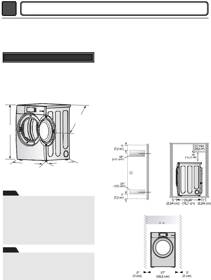
 STEP 1 Positioning the Dryer.
Choose a location with a solid floor for your dryer. Place the dryer at least eighteen inches above the floor for a garage installation. After placing the dryer in the desired location, please make sure that it has the required clearances shown below, and sections on Exhaust and Maintenance requirements.
49.8” (126.4 cm)
38.7” (98.3 cm)
27” |
29.96” |
(68.6 cm) |
(76.1 cm) |
*Most installations require a minimum 5 1/2 in. (14 cm) clearance behind the dryer for the exhaust vent with elbow.
Note
Level the dryer using the leveling legs and tighten the adjusting nuts to hold them in place.
All four legs should be placed firmly on a solid and even floor.
If the dryer is not level, the clothes will not tumble properly and the sensor will not be able to detect the dryness level accurately.
Adjust the leveling legs carefully to avoid injury.
Note
No other fuel-burning appliance shall be installed in the same closet as the dryer.
This applies only to dryers suitable for installation in a closet.
Certain minimum clearances are required above, behind, and to the sides of the unit, as shown below. Those required minimum clearances are set forth in the picture below. Please also keep the following instructions in mind when installing in a closet or recessed area:
•Consider allowing additional clearance for installation and servicing.
•Wall, door and floor molding may force additional clearances.
•An additional inch of clearance is recommended to minimize noise transfer .
•Consider space needed for companion appliances.
•For closet installations, the picture below shows the minimum required ventilation openings for the door. A louvered door with comparable ventilation openings is also acceptable.
ventilation |
hole |
ventilation |
hole |
Closet door |
|
|
|
|
Closet-Side view |
|||||
|
|
|
|
|
|
|
|
|
|
|
|
|
|
|
|
|
|
|
|
|
|
|
|
|
|
|
|
|
|
|
|
|
|
|
|
|
|
|
|
|
|
|
|
|
|
|
|
|
|
|
|
|
|
|
|
|
|
|
|
|
|
|
|
|
|
|
|
|
|
|
|
|
|
|
|
|
13 |
Closet-Front view |
Once in position, adjust the leveling legs of the dryer until it is level from left to right and from front to back. The leveling legs must remain firmly on the floor and the dryer should not rock. The maximum slope of the dryer from left to right or from front to back should not exceed 2.5 cm (1 inch). If the dryer is not level, and if the slope exceeds 2.5 cm (1 inch), a load may not tumble properly and internal sensors may malfunction. Note: Other sections of this manual also provide important information concerning the placement of and clearances for your dryer. Please review this entire manual before proceeding with any installation.
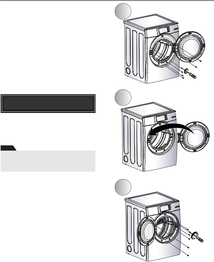
STEP 2 Procedure for Reversing the Door
The door on your dryer can be installed to open either to the left or the right. Follow these procedures to reverse the direction in which your door opens:
Note
Door and latch should be aligned at the center when closed. Otherwise, the door will not open, close, or latch properly.
1
2
3
14
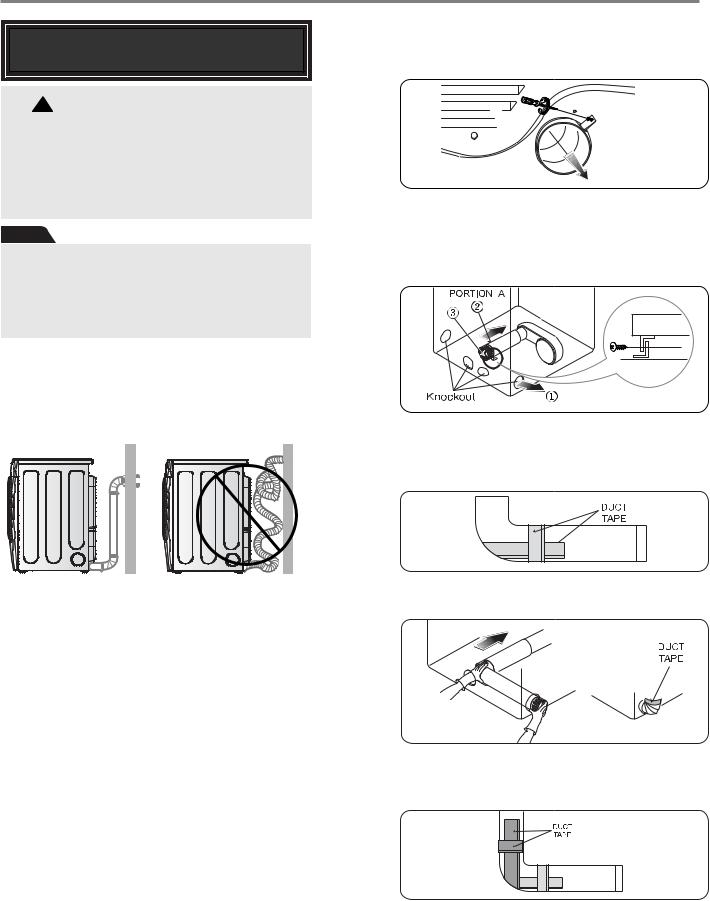
STEP 3 Connecting the Exhaust
and Venting System.
!WARNING
•Use a heavy metal vent.
•Do not use plastic or thin foil duct.
•Clean old ducts before installing this dryer
•Failure to follow these instructions can result in death or fire.
Note
Vent pipe and fittings must be installed with the smaller ends facing away from the dryer. Incorrect installation of the vent and improper taping of the joints will interfere with correct dryer and vent function.
In addition to the following warnings, please refer to manual section on Exhaust Requirements and Maintenance. IMPORTANT: To reduce the risk of fire, combustion, and gas accumulation, the dryer must be vented to the outdoors. Please follow the instructions (and all others in this manual) very carefully.
•Do not use plastic or thin foil duct.
•Use 4" (10.2 cm) diameter rigid or semi-rigid metal duct (note: venting materials are not supplied with the dryer, and you must obtain the venting materials necessary for proper installation)
•Position the dryer so the exhaust duct run is as short as possible.
•Clean old ducts before installing this dryer
•The male end of each section of exhaust duct must point away from the dryer
•Use as few elbow joints as possible.
•Use duct tape on all duct joints
•Insulate ductwork that runs through unheated areas in order to reduce condensation and lint build-up on pipe walls; and
•PLEASE BE AWARE THAT FAILURE TO EXHAUST THE DRYER CORRECTLY WILL
VOID THE DRYER’S WARRANTY. |
15 |
■ALTERNATE EXHAUST DIRECTIONS
1.Remove the screw that attaches the duct's tab to the dryer.
2-1. Detach and remove the knockout that matches the desired venting direction (Right side not available on Gas Dryers)
Follow steps 1, 2, and 3, as shown below.
2-2. Reconnect the duct to the blower housing and attach the duct to the base. The side vent kit is available as a service part, #383EEL9001B.
3-1. Pre-assemble a 4" elbow with a 4" duct. Wrap duct tape around joint.
3-2. Insert the elbow duct assembly first through the side opening and connect the elbow to the internal duct.
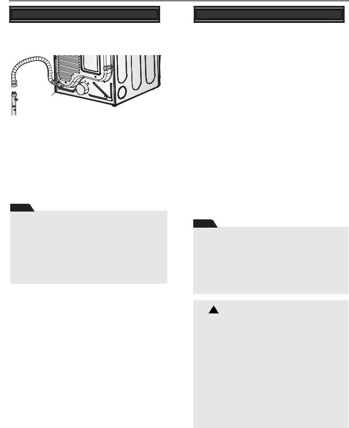


 STEP 4 Connection of Gas Supply


(Gas dryer only). In addition to the following, please refer to manual section on Gas Requirements and Instructions.
 1
1


 2
2
5
 3
3  4
4
1.New stainless steel flexible connector. Use this type of connector only if allowed by local codes. Use Design AGA Certified Connector.
2.1/8" NPT Pipe Plug (for checking inlet gas pressure)
3.Equipment Shut-Off ValveInstalled within 6'(1.8m) of dryer
4.Iron Pipe. Shorter than 20'(6.1m)
Use 3/8" pipe. Longer than 20'(6.1m) - Use 1/2" pipe.
5.3/8" N.P.T. Gas Connection
6.Apply pipe joint compound or about 1 1/2 wraps of Teflon tape over all threaded connection
Note
Make sure the burner orifice is proper for the type of gas you are provided with.
For instance, using LPG with LNG orifice will result in death, fire, or explosion. Using LNG with LPG orifice will not ignite burner.
If needed, orifice conversion should be done by a qualified service technician and mark or place the label of the current type of orifice on the dryer.
1.Confirm that the type of gas available in your laundry room is appropriate for the dryer. The dryer is prepared for Natural Gas with a 3/8" NPT gas connection.
2.Remove the shipping cap from the gas connection at the back of the dryer. Make sure that you don’t damage the threads of the gas connection pipe when you remove the shipping cap.
3.Connect the dryer to your laundry room’s gas supply using a new flexible stainless steel connector (as noted below, only use a new stainless steel flexible connector if allowed by your local codes).
4.Securely tighten all connections between the dryer and your laundry room’s gas supply. Turn on your laundry room’s gas supply and check all pipe connections (both internal and external) for gas leaks with a non-corrosive leak detection fluid. Refer to Part 7 (page 20)
5.For LP (Liquefied Petroleum) gas connection, refer to
this manual’s section entitled Gas Requirements and |
16 |
|
Instructions. |
||
|


 STEP 5 Electrical Plug Connections


Following are several warnings and instructions concerning making the electrical connection for electric dryers. More detailed information concerning the electrical connection is provided at the manual section entitled Electrical Requirements for Electric Dryer.
It is important that you thoroughly review that section, and the remainder of this manual before taking any steps to install or use this dryer.
1.Use only a new U.L. listed No. 10 (copper wire only) three conductor power supply cord kit rated 240 Volts (minimum) 30 Amperes and labeled as suitable for use in a clothes dryer.
2.Four-wire cord is required for manufactured (mobile) home installations and use and where local codes do not allow grounding of this appliance through neutral.
3.Electrical Plug Connections.
4.For additional instruction on connecting the dryer to an electrical power source, please refer to this manual’s section on Electrical Requirements and Electric Dryer.
Note
Burner input requirements:
Adjusting burner input setting is not needed (at the elevation up to 10,000 feet) because AGA certifies this dryer will not have any problem with the BTU rating. If your house is at above 10,000 feet, you are required to adjust a four percent (4%) reduction of the burner BTU rating indicated on the model/serial rating plate.
!WARNING
•Use a new UL approved 30 amp power supply cord or 10 gauge solid copper wire.
•Use a UL approved strain relief.
•Disconnect power before making electrical connections.
•Connect neutral wire (white or center wire) to center terminal.
•Ground wire (green or bare wire) must be connected to green ground connector.
•Securely tighten all electrical connections
•See installation instructions for complete instructions.
•Failure to do so can result in fire or electrical shock.


 STEP 6 Preparation of the Dryer


Prior to the first use of this appliance, use allpurpose cleaning products or a solution of detergent and water, with damp clothes to remove from the inside of the dryer drum/drying compartment any dust or dirt that may have accumulated the inside of the dryer. Plug-in your dryer after reviewing the following parts on your dryer’s Electrical Requirements.
STEP 7 Confirming Heat Source
Operation
Confirming Heat Source in Gas Dryers
Close the door to the dryer drum/drying compartment and, after completing all steps in this manual for proper installation of this dryer, start the dryer on a heat setting, as described more fully in the operating instructions that accompany the dryer. After the dryer starts, the igniter will glow red and the main burner will ignite.
Warning: If all air is not purged from the gas line, the gas igniter may go off before the gas and the main burner have ignited. If this happens, the igniter will re-attempt gas ignition after approximately two minutes.
Confirming Heat Source in Electric Dryers
Close the door to the dryer drum/drying compartment and, after completing all steps in this manual for proper installation of this dryer, start the dryer on a heat setting, as described more fully in the operating instructions that accompany the dryer. The exhaust air or the exhaust pipe should be warm after the dryer has been operating for three minutes.


 STEP 8 Dryer Airflow
Effective dryer operation requires appropriate dryer airflow. The adequacy of the airflow can be measured by evaluating the static pressure. Static pressure in the exhaust duct can be measured with a manometer, placed on the exhaust duct approximately 2 ft. (60.9 cm) from the dryer. Static pressure in the exhaust duct should not exceed 0.6 inches (1.5 cm). The dryer should be checked with the dryer running with no load.
Measuring Static Pressure
Manometer1
 Exhaust2 Duct
MAXIMUM STATIC
PRESSURE IN
WATER COLUMN
0.6inche (1.5 cm)
!WARNING
•The dryer must be disconnected from the gas supply piping system during pressure testing.
•Failure to do so can result in death, explosion, or fire.
17

5 |
INSTALLATION INSTRUCTIONS |
Assembly Coin/Card Type Housing
1 Coin/Card housing
How to connect the housing
The dryer has a connector for both a coin collector and a card reader. Use the one you need and tuck the other one away safely.
2 COIN TYPE
When power on the machine at first time without connecting card reader or coin housing ,display will show LqC1
Coin housing
Card reader housing
3 CARD TYPE
18 |
!WARNING
•Disconnect power before service.
•Failure to follow these instructions can result in death or electrical shock.
 Loading...