

Page 1
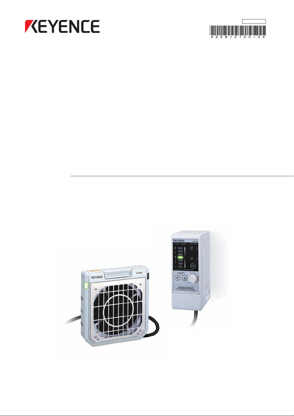
High-speed, High-precision
Compact Static Elimination Blower
SJ-F100W/100/010
Instruction Manual
Before using this Compact Static Elimination Blower, be sure to
thoroughly read this Instruction Manual.
After you are finished with this Instruction Manual, be sure to store it in a
safe place for quick reference.
96M10750
Page 2
Preface
DANGER
WARNING
CAUTION
Important
Note
Reference
This document describes handling, method of operation and precautions when using the High-speed,
High-precision Compact Static Elimination Blower Unit SJ-F100W/100/010. Before you start to use the
SJ-F100W/100/010, be sure to thoroughly read this document in order to make full use and safely use
the functions of the SJ-F100W/100/010.
Store this document in a safe place so that you can retrieve it whenever necessary.
Symbols
This manual uses the following symbols to alert you to important information.
Failure to follow these instructions may lead to death or serious injury.
Failure to follow these instructions may lead to injury.
Failure to follow these instructions may lead to physical damage (product
malfunction, etc.).
Provides additional information on precautions and restrictions that must be
followed in operation.
Provides additional information on proper operation.
Indicates useful information or information that aids understanding of text
descriptions.
Indicates a reference item or page to be referred to in this manual and a separate
manual.
Page 3
Safety Precautions
CAUTION
WARNING
CAUTION
General Precautions
• At startup and during operation, be sure to monitor the functions and
performance of the SJ-F100W/100/010.
• We recommend that you take substantial safety measures to avoid any
damage in the event that a problem occurs.
• Do not modify the SJ-F100W/100/010 or use it in any way other than described
in the specifications. The functions and performance of products used or
modified in this way cannot be assured.
• When the SJ-F100W/100/010 is used in combination with other instruments,
functions and performance may be degraded, depending on operating
conditions and the surrounding environment.
• Do not use the SJ-F100W/100/010 for the purpose of protecting the human
body.
SJ-F100W/100/010 Handling Precautions
The SJ-F100W/100/010 is a high-voltage product that is not designed in an explosionproof structure. Pay
attention to the following when using the SJ-F100W/100/010.
• To prevent electric shock and to ensure accurate static elimination, be sure to
connect a Class D earth (maximum resistance of 100 Ohms).
• Do not use this product in locations where there is the risk of ignition or
explosion from flammable solvents or dirt and dust.
• High voltage is applied to this product. Prevent it from being splashed with
water, oil, or flammable solvents. Failure to do so might cause insulation
breakdown, which will result in electric shock or malfunction.
• Do not bring your fingers or tools, wire or other metallic objects near this
product.
Doing so might cause electric shock or malfunction.
• Do not use this product in a non-ventilated location. The ozone generated
from this product may become toxic. Be sure to ventilate the installation site
when this product is used in a non-ventilated location.
• Do not use this product in locations where sudden changes in temperature or
condensation are likely to occur.
• Do not operate this product with wet hands. Doing so might cause electric
shock.
• Before starting maintenance, be sure to turn the power OFF. Failure to do so
might result in electric shock or malfunction.
• During maintenance, do not directly touch the electrode needles. Doing so
might cause personal injury.
• If any malfunction is observed in this product, immediately turn it OFF, and
contact your nearest agent. You should never repair this product yourself.
Doing so might cause electric shock or malfunction.
Do not touch the electrode needles with a tool or other hard object. Damage to
the electrode needles will prevent static elimination performance from being
fully demonstrated, and cause accidents or malfunction.
96M10750
i
Page 4
• When this product is used for a long period of time, the electrode needles
CAUTION
CAUTION
CAUTION
SJ-F010
Be sure to turn the power off when replacing
the electrode probes. Otherwise, electric shock may occur.
Do not touch electrode probes with your hands
or fingers, as this may cause injury.
WARNING
* WARNING labels in Japanese, German, French and Italian are provided.
Use them as necessary.
become dirty due to the adhesion of dust and dirt. If the ion level alarm
indicator or condition alarm indicator lights, clean the electrode needles. If
the electrode needles are used in a dirty or dusty state, the static elimination
performance can no longer be fully demonstrated, resulting in accidents or
malfunction. We recommend periodically cleaning the electrode needles (as a
guideline, once every two weeks in a regular operating environment though
this depends on the installation conditions).
• Do not drop or subject this product to shock. Doing so might result in
accident or malfunction.
• Use this product for static elimination only. Do not use it for other purposes.
Power Supply Precautions
• Use a DC power supply with rated 24 V output.
• Noise applied to the power supply may cause this product to malfunction. If
this happens, install an insulated transformer.
• When using a switching regulator, be sure to connect a Class D earth to the
Frame Ground terminal.
Grounding Precautions
• To ensure safety and appropriate static elimination, be sure to ground this
product.
• Be sure to connect a Class D earth (maximum resistance of 100 Ohms)
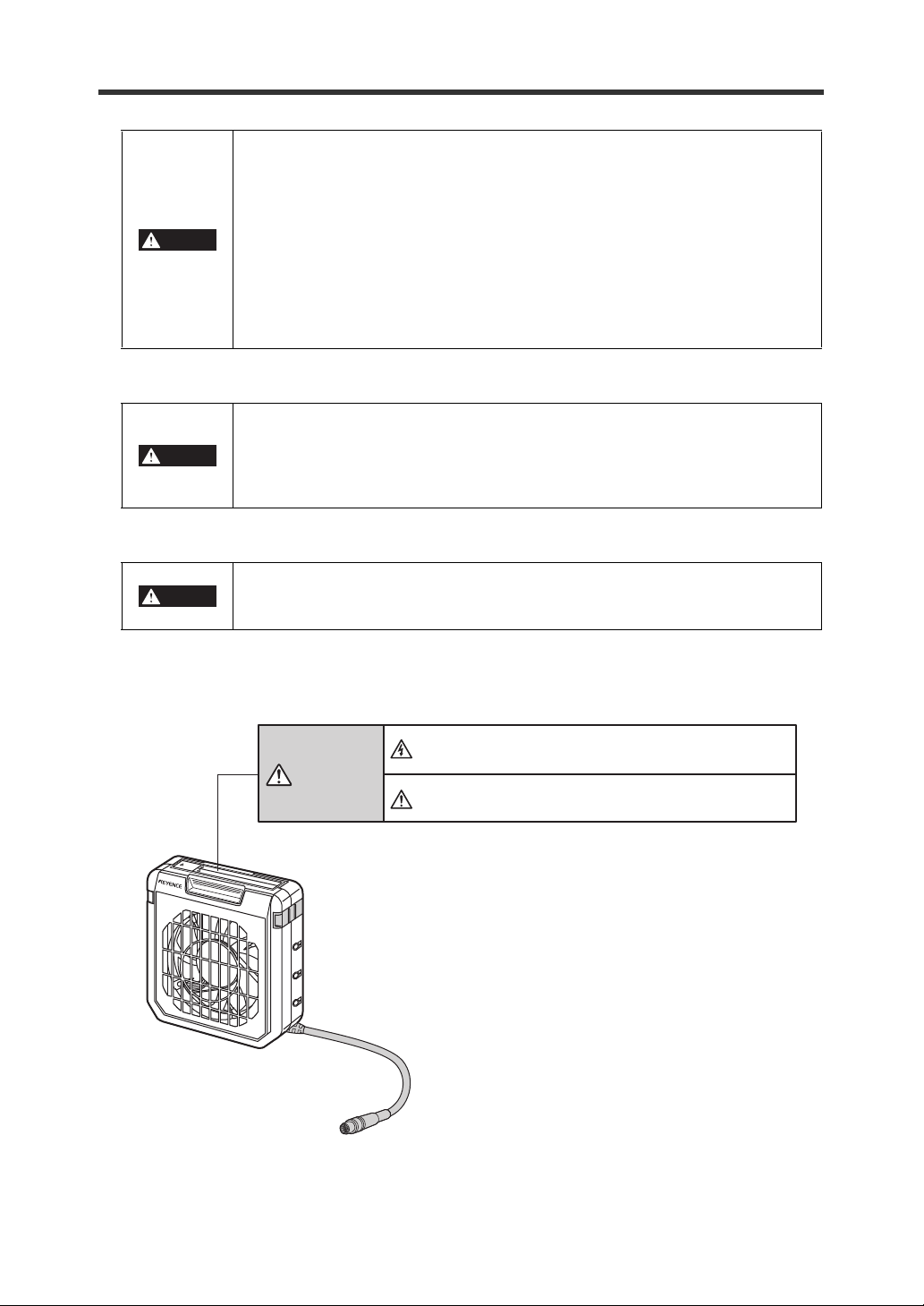
SJ-F100W/100/010 Warning Label
A WARNING label is affixed on the SJ-F100W/100/010 to ensure safety.
Read the description on this WARNING label to ensure correct use of the SJ-F100W/100/010.
ii
Page 5
Installation Precautions
CAUTION
Note
CAUTION
CAUTION
Avoid installing the SJ-F100W/100/010 in the following locations as this may cause accidents.
• Locations directly subject to vibration and shock
• Locations subject to ambient temperature out of the 0°C to +50°C range
• Locations subject to ambient humidity out of the 35 to 65%RH range
(condensation not allowed)
• Locations subject to sudden changes in temperature
• Locations subject directly from blasts from air conditioners
• Locations subject to voltatile or flammable substance, solvents or corrosive
gases
• Locations subject to large amounts of dirt, and dust, salt, iron and oil smoke
• Locations that may be splashed with water, oil or chemical mist
• Locations where strong magnetic and electrical fields are generated
About Warming up the SJ-F100W/100/010
Leave the SJ-F100W/100/010 for about 20 minutes after turning the power ON to
allow the ion balance to stabilize.
The ion balance may be unstable during this warming up period.
Other Precautions
• Be sure to read the WARNINGS and CAUTIONS described in each of the items
in this Instruction Manual.
• The Static Elimination Blower Unit has a built-in EEPROM. Do not turn the
Static Elimination Blower Unit OFF during the setup.
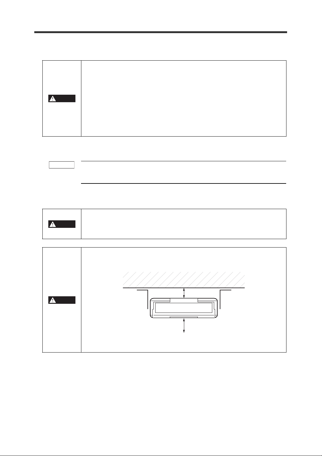
Refer to the following diagram when installing the SJ-F100W/100/010.
• Install the Static Elimination Blower Unit away from the wall or surrounding
objects.
30 mm or more
50 mm or more
• Install the Static Elimination Blower Unit so that the Electrode Unit can be
removed for replacement.
iii
Page 6

This page left intentionally blank
iv
Page 7

How This Manual Is Organized
This chapter describes the features of the Static Elimination Blower Unit
SJ-F100W/100/010, and the names and functions of parts.
About the Static
Elimination Blower Unit
SJ-F100W/100/010
1
This character describes how to connect and install the Static Elimination
Blower Unit SJF100W/100/010.
Connection and
Installation
2
This chapter describes the functions of the Static Elimination Blower Unit
SJ-F100W/100/010.
SJ-F100W/100/010
Functions
3
This chapter describes how to perform maintenance on the Static
Elimination Blower Unit SJ-F100W/100/010 and electrode needles.
Maintenance
4
This chapter describes the specifications, timing charts and external
dimensions of the Static Elimination Blower Unit SJ-F100W/100/010.
Specifications
5
These appendices list the options for the Static Elimination Blower Unit
SJ-F100W/100/010 and describe how to remedy trouble.
Appendices
1
2
3
4
5
v
Page 8

Contents
Preface
Safety Precautions .................................................................................................................... i
How This Manual Is Organized ................................................................................................ v
Contents ................................................................................................................................... vi
Precautions on Regulations and Standards ....................................................................... viii
Conventions Used In This Manual ......................................................................................... ix
Page Configuration and Symbols ......................................................................................ix
Terminology .......................................................................................................................ix
Chapter 1
1-1 Features of the SJ-F100W/100/010 .............................................................................. 1-1
1-2 Checking the Contents of the Package ...................................................................... 1-3
1-3 Names and Functions of Parts .................................................................................... 1-4
About the Static Elimination Blower Unit SJ-F100W/100/010
Outline of the SJ-F100W/100/010 .............................................................................. 1-1
Package Contents ...................................................................................................... 1-3
Options ....................................................................................................................... 1-3
Static Elimination Blower Unit .................................................................................... 1-4
Controller Unit (operation/display section) ................................................................. 1-5
Controller Unit (I/O terminal section) ..........................................................................1-6
Chapter 2 Connection and Installation
2-1 Before Installation ........................................................................................................2-1
About Static Elimination Performance ........................................................................ 2-1
Installation Precautions ..............................................................................................2-3
2-2 Connection and Installation ........................................................................................2-4
Installing the SJ-F100W/100/010 ............................................................................... 2-4
Connecting Cables .....................................................................................................2-6
Chapter 3 SJ-F100W/100/010 Functions
3-1 Fan Speed Adjustment Function ................................................................................ 3-1
Fan Speed Adjustment Function ................................................................................ 3-1
3-2 Ion Monitor Functions .................................................................................................. 3-2
Ion Monitor Functions ................................................................................................. 3-2
3-3 Alarm Output Functions .............................................................................................. 3-3
Alarm Output Functions ............................................................................................. 3-3
3-4 Other Functions ............................................................................................................3-4
Abnormal Discharge Detection Function .................................................................... 3-4
Ion Balance Adjustment Function .............................................................................. 3-4
Static Elimination Stop Function ................................................................................ 3-6
vi
Page 9

Chapter 4 Maintenance
4-1 About Maintenance ...................................................................................................... 4-1
About Maintenance ....................................................................................................4-1
4-2 Performing Maintenance on the Electrode Needles .................................................. 4-2
Performing Maintenance on the Electrode Needles ................................................... 4-2
Chapter 5 Specifications
5-1 Timing Charts ...............................................................................................................5-1
5-2 Specifications ...............................................................................................................5-3
5-3 External Dimensions ....................................................................................................5-4
Appendices
1 Troubleshooting ...............................................................................................................A-1
2 Table of Indicated States ................................................................................................. A-2
3 List of Options .................................................................................................................. A-7
4 Index .................................................................................................................................. A-8
vii
Page 10

Precautions on Regulations and Standards
CE Marking
Keyence Corporation has confirmed that this product complies with the essential requirements of the
applicable EC Directive, based on the following specifications.
Be sure to consider the following specifications when using this product in the Member State of
European Union.
● EMC Directive (2004/108/EC)
• Applicable standard: EN61326-1
• Be sure to provide a ground when installing the SJ-F100W/100/010.
• The length of cable (power lead and I/O leads) must be less than or equal to 30 m.
Remarks:
These specifications do not give any guarantee that the end-product with this product incorporated
complies with the essential requirements of EMC Directive. The manufacturer of the end-product is
solely responsible for the compliance on the end-product itself according to EMC Directive.
● Low-Voltage Directive (2006/95/EC)
• Applicable standard: EN61010-1
• Overvoltage category I
• Use this product under pollution degree 2.
• Use the power supply for the SJ-F100W/100/010, that satisfies the requirements of the Limited
Power Source specifications stipulated in EN60950-1 and certified by European third-party
certification organization, or a Keyence Corporation AC adapter (SJ-U2). The specifications of the AC
adapter (SJ-U2) are as follows.
When connecting to an SJ-U2, be sure to use a power cable compliant with European standards.
Applicable standard: EN60950-1
Overvoltage category II
Pollution degree 2
• Be sure to provide a ground when installing the SJ-F100W/100/010.
viii
Page 11
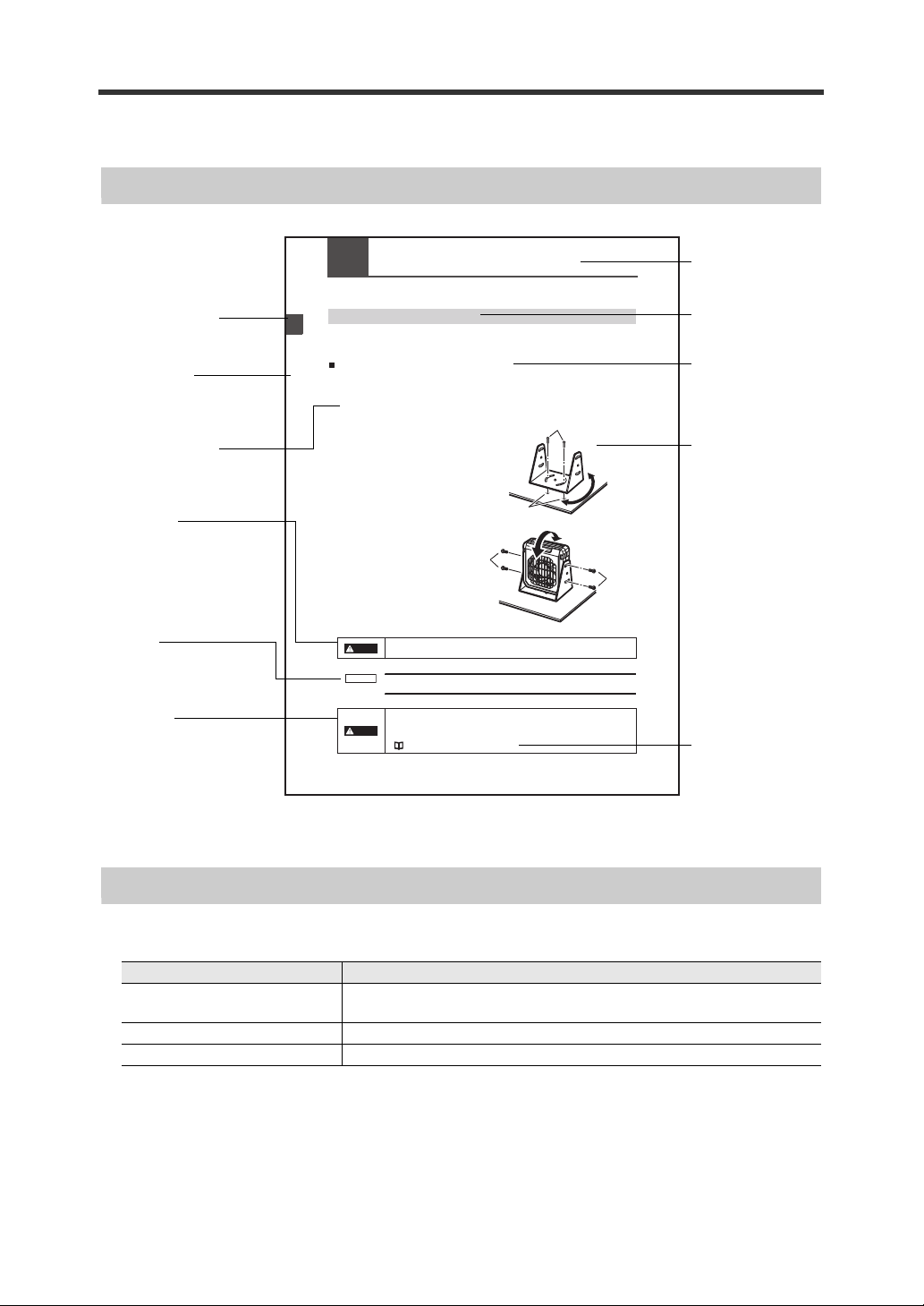
Conventions Used In This Manual
Installing the SJ-F100W/100/010
Install the SJ-F100W/100/010 at locations where static electricity is generated or is likely to be
generated.
Installing the Static Elimination Blower Unit
There are two ways of installing the Static Elimination Blower Unit, with or without the mounting fixtures.
When using mounting fixture A:
1 Tap M4 screw holes where the Static Elimination Blower Unit is to be installed, and fasten
mounting fixture A (OP-51409) with the M4 screws.
You can adjust the horizontal angle of the
Static Elimination Blower Unit by using the
semi-circled cutout holes on the base of
mounting fixture A.
The M4 screws for fastening mounting
fixture A at the installation location must
be provided separately.
2 Install the Static Elimination Blower Unit on mounting fixture A.
You can adjust the vertical angle
of the Static Elimination Blower
Unit by using the semi-circled
cutout holes on the base of
mounting fixture A.
The M4 screws for fastening
mounting fixture A to the Static
Elimination Blower Unit are
provided with mounting fixture A.
Install the Static Elimination Blower Unit so that it can be easily accessed, for
example, for replacement of parts and cleaning.
M4 screws
M4 tapped holes
To prevent electric shock and to ensure accurate static elimination, be sure to
connect a Class D earth (maximum resistance of 100 Ohms).
• Install the Static Elimination Blower Unit away from the wall or surrounding
objects.
• Install the Static Elimination Blower Unit so that the Electrode Unit can be
removed for replacement.
"Installation precautions" page 2-3
S
J-F010
M4 screws
M4 screws
Note
Thumbnail index
Indicates the chapter.
Chapter title
Operational step
Warn ing
The user may be subjected
to physical harm (electric
shock, burns, etc.) if he
does not observe the
particulars described here.
Caution
Failure to observe the
caution described here may
result in product trouble.
Note:
Describes cautions for
easily mistaken operations.
Be sure to read these.
Headline
Mid-heading
Sub-heading
Illustration
Reference page
Indicates the page to
refer to. The page
containing the related
information is
indicated here.
* This page was made for the purpose of explaining page components,
and differs form an actual page.
The following shows how pages are configured, and the symbols and terminology used in this manual.
Page Configuration and Symbols
2-2 Connection and Installation
This section describes how to connect and install the Static Elimination Blower Unit and Controller Unit.
2
Connection and Installation
Terminology
This manual uses the following terminology excluding some instances.
SJ-F100W/100/010 General term for the Compact Static Elimination Blower SJ-F100W/100/
Static Elimination Blower Unit SJ-F010
Controller Unit SJ-F100W/100
WARNING
CAUTION
Term Description
2-4
010
ix
Page 12

This page left intentionally blank
x
Page 13
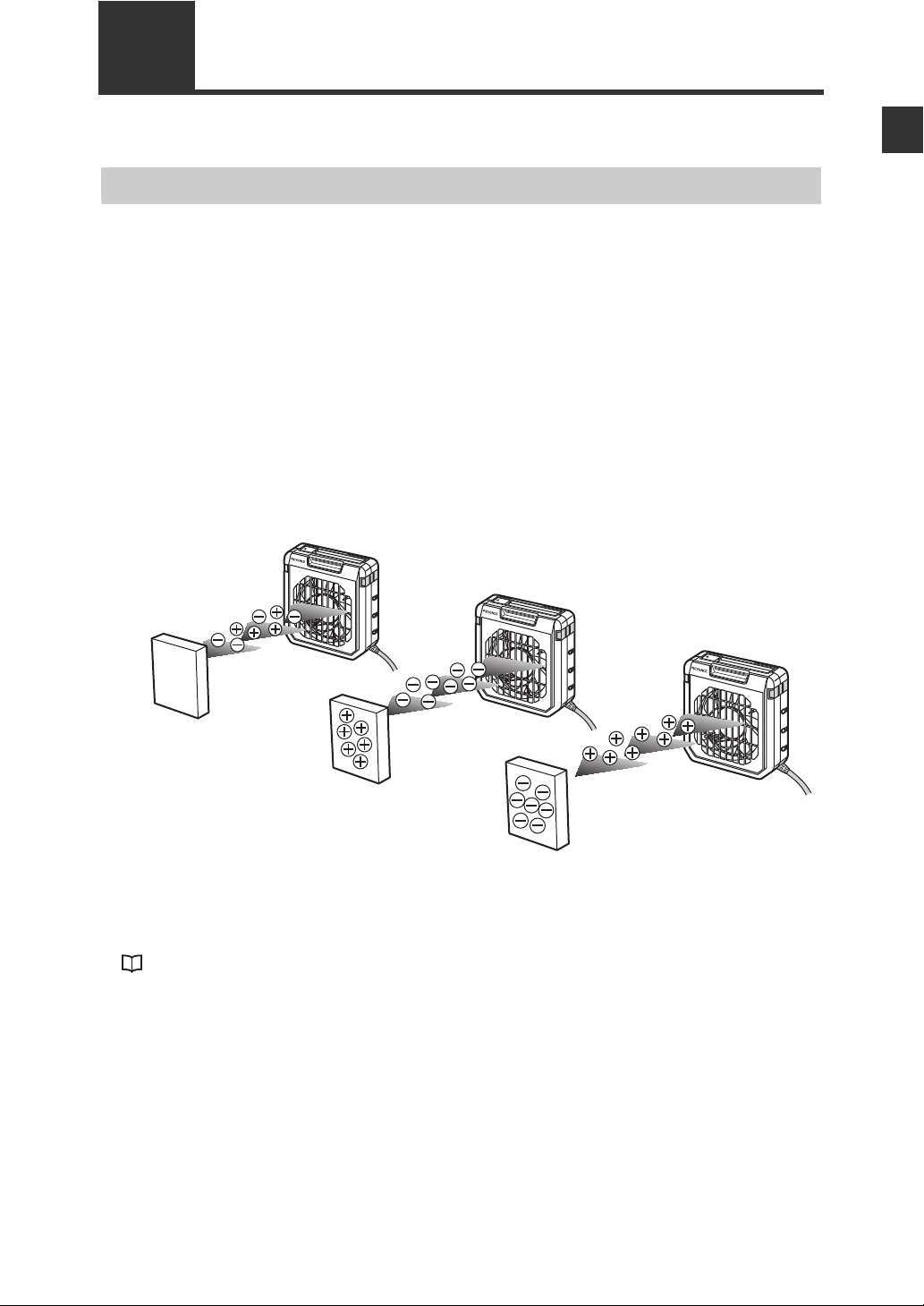
Chapter 1About the Static Elimination Blower Unit SJ-F100W/100/010?
SJ-F010
SJ-F010
SJ-F010
Target object in
non-charged state
Target object (+) charged
Regular state
Elimination of (–) ions
from target object
Target object (–) charged
Elimination of (+) ions
from target object
1-1 Features of the SJ-F100W/100/010
This section describes an outline of the functions, the features of the SJ-F100W/100/010.
Outline of the SJ-F100W/100/010
Variable DC method
The SJ-F100W/100/010 uses a variable DC method that generates + and - charged air ions from
separate electrode needles, respectively. The generation of + and - ions ensures a stable ion balance
free from fluctuation in the + and - charges.
The SJ-F100W/100/010 also automatically controls the amount of + and - ions generated matched to the
charged state of the target object, degree of dirt on the electrode needles, and other factors. This
enables high-speed and high-precision static elimination suited to installation conditions and conditions
of use.
I.C.C. (Ion Current Control) method
This control method calculates the charged level of the target object by sensing the state of ion current
that arises due to the potential between the Static Elimination Blower Unit and GND. Optimum static
elimination matched to the state of the target object can be performed by rapidly supplying the optimum
ions suited to the polarity and charged level of the target object.
1
About the Static Elimination Blower Unit SJ-F100W/100/010
Fan speed adjustment function
The blast from the Static Elimination Blower Unit is adjusted. This fulfils a vital role
in improving static elimination speed and extends the static elimination area.
"Fan Speed Adjustment Function" (page 3-1)
1-1
Page 14
1-1 Features of the SJ-F100W/100/010
1
Ion monitor function
About the Static Elimination Blower Unit SJ-F100W/100/010
● Charge monitor
The integrated ion monitor allows you to learn how much the target object is charged by + or - ions. This
monitor also allows you to confirm at a glance how static elimination is being performed.
● Ion level monitor
The ion level currently being generated by the Static Elimination Blower Unit is monitored at all times so
that drops in the generated ion level can be diagnosed on the unit. The generated ion level is indicated by
LEDs and an alarm can be output when the generated ions fall below a certain level. This allows you to
monitor the influence of dirty electrode needles in advance.
"Ion Monitor Functions" (page 3-2)
Alarm output functions
● Alarm output functions
An indicator blinks and an alarm signal is output, for example, when internal circuits are damaged or
abnormal discharging occurs. When an alarm signal is output, generation of ions is forcibly stopped.
● Ion level alarm output function
An indicator lights and an alarm signal is output when the amount of generated ions drops due to dirty
electrode needles, for example.
● Condition alarm output function
An indicator lights and an alarm signal is output when static elimination performance is influenced by an
unstable installation environment (temperature, humidity, surrounding metal objects, etc.)
"Alarm Output Functions" (page 3-3)
Abnormal discharge detection function
Abnormal discharge caused by condensation on the electrode needle tips or adhesion of debris is
detected. When abnormal discharge is detected, ion generation is forcibly stopped to prevent trouble at
an early stage.
"Abnormal Discharge Detection Function" (page 3-4)
Ion balance adjustment function
The ion balance zero point can be fine-adjusted.
"Ion Balance Adjustment Function" (page 3-4)
Static elimination stop function
Static elimination only can be turned ON/OFF with the device still powered. This is achieved by shorting
the 0V terminal with the static elimination stop input terminal on the Controller Unit (I/O terminal section)
or by holding down the two ion balance adjustment keys simultaneously for about three seconds.
"Static Elimination Stop Function" (page 3-6)
Low voltage power-saving wiring
Low-voltage wiring eliminates deterioration of cables caused by discharging and eliminates the influence
on surrounding devices. This enables you to build a highly reliable system.
1-2
Page 15
1-2
+
–
0
BALANCE
ION
ION
LEVEL
COND
FAN
SPEED
SLOW
24V DC
OV
ALARM
CONDITION
INTERR
UPT
ION LEVEL
FAS
T
DISP
H
M
L
H
M
L
ALARM
SJ-F100W
ION BALANCE
ADJAST
SJ-F010
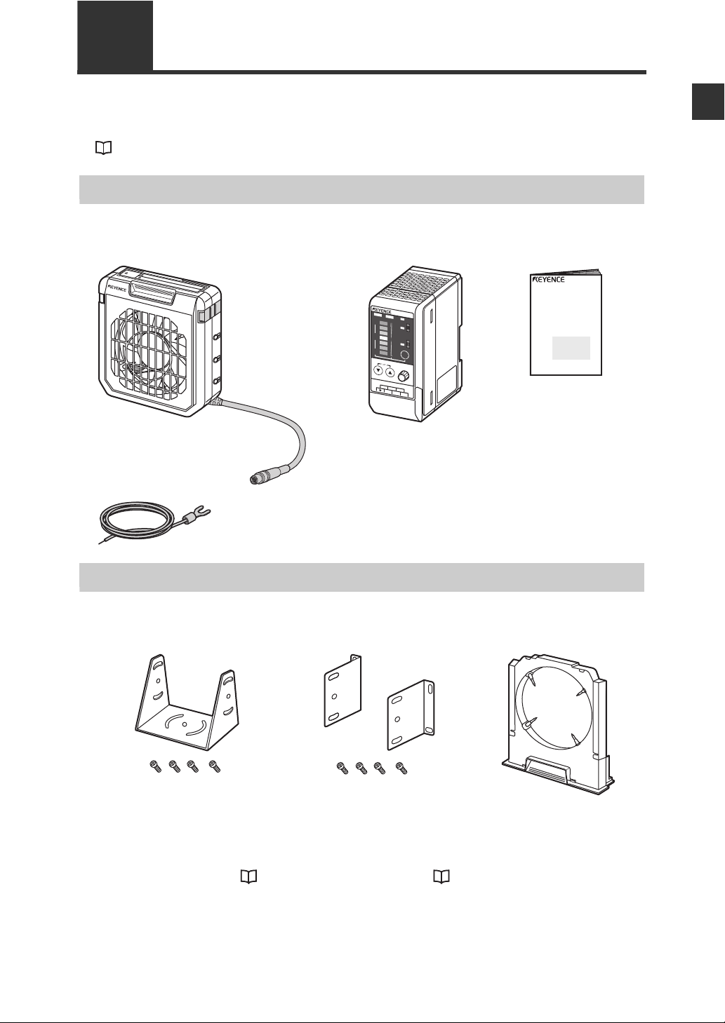
Static Elimination Blower Unit
(SJ-F010)
Controller Unit
(SJ-F100W/100)
Instruction Manual
Earth lead
WARNING labels (Japanese, German,
French and Italian)
* Use them as necessary.
Checking the Contents of the Package
The package contains the f ollo wing component s and accessories . Bef ore y ou start using SJ-F100W/100/
010, make sure that the package contains everything that it is supposed to contain. Mounting fixtures,
Replacement Electrode Unit and other accessories are available as options.
"List of Options" (page A-7)
Package Contents
High-speed, High-precision
Compact Static Emilination Blower
SJ-F100W/100/010
Instruction Manual
1
About the Static Elimination Blower Unit SJ-F100W/100/010
Options
Mounting fixture A
(OP-51409)
*1 This fixture is provided with
four M4 screws for mounting
the Static Elimination Blower
Unit.
*2 For details on how to install
mounting fixture A, see
"When using mounting fixture
A:" (page 2-4).
Mounting fixture B
(OP-51410)
*1 This fixture is provided with
four M4 screws for mounting
the Static Elimination Blower
Unit.
*2 For details on how to install
mounting fixture B, see
"When using mounting fixture
B:" (page 2-5).
Replacement Electrode
Unit (OP-51407)
1-3
Page 16
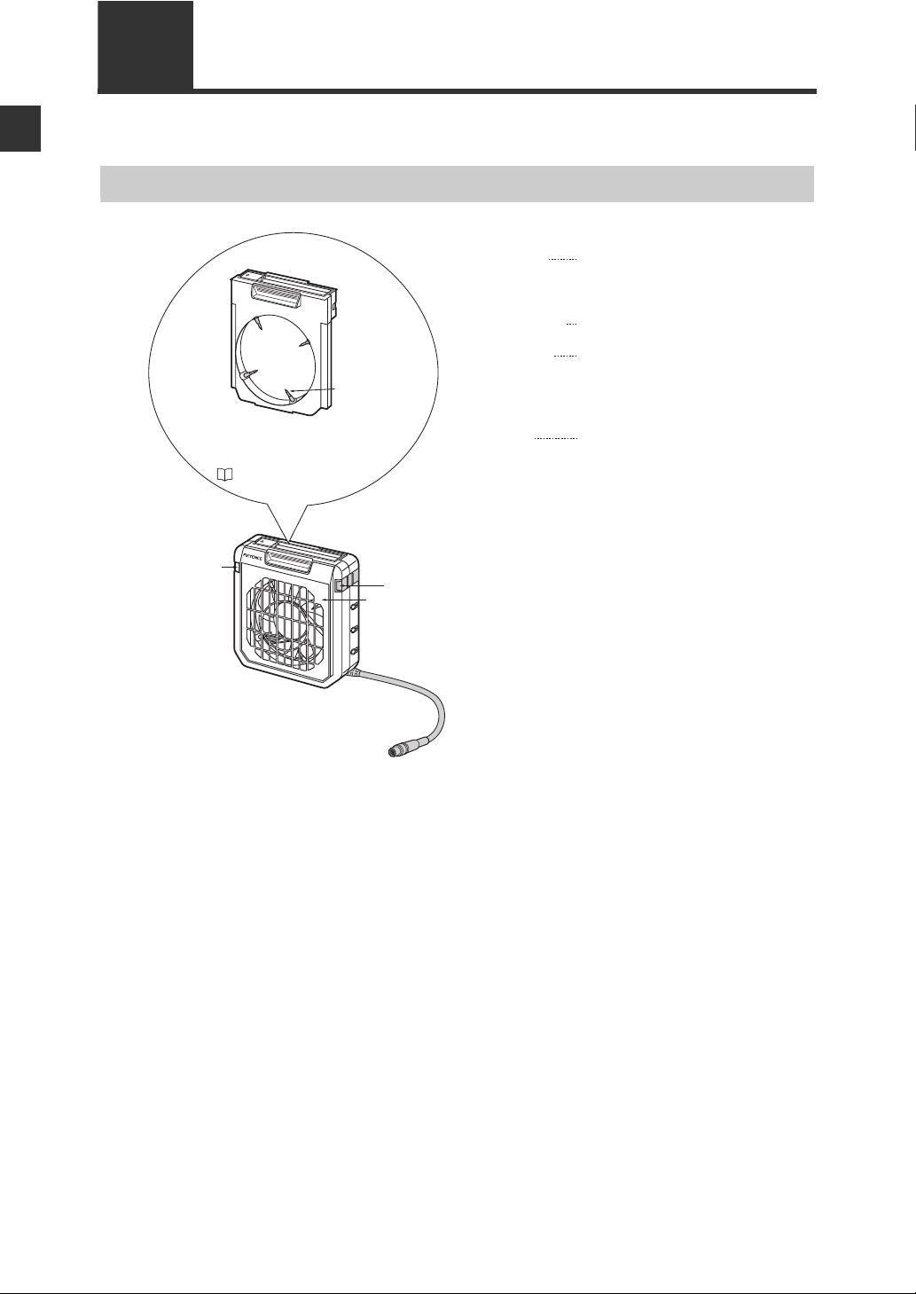
1-3 Names and Functions of Parts
(4) Lock switch
(3) Power indicator
Fan guard (metal)
(1) Electrode Unit The electrode needles are fixed on the
Electrode Unit. Remove this unit from the
Static Elimination Blower during
maintenance and inspection.
(2) Electrode needles Ion charge is emitted from the tips of these
needles.
(3) Power indicator Indicates the operating state of the
SJ-F100W/100/010.
Lit (green): Regular operation
Lit (red): Static elimination is stopped.
Blinking (red): Alarm has occurred.
(4) Lock switch Fixes the Electrode Unit to the Static
Elimination Blower.
SJ-F010
(1) Electrode Unit
(2) Electrode
needle
For details on how to install and remove
the Electrode Unit, see "Performing
Maintenance on the Electrode Needles"
( page 4-2).
1
This section describes the names and functions of parts on the SJ-F100W/100/010.
About the Static Elimination Blower Unit SJ-F100W/100/010
Static Elimination Blower Unit
1-4
Page 17
1-3 Names and Functions of Parts
+
–
0
BALANCE
ION
ION
LEVEL
COND
FAN SPEED
SLOW
24V DC OV ALARM
CONDITION INTERRUPT
ION LEVEL
FAST
DISP
H
M
L
H
M
L
ALARM
SJ-F100W
ION BALANCE
ADJUST
Enlarged view of front panel display
Terminal plate cover
+
–
0
B
AL
AN
CE
ION
ION
LEVEL
COND
FAN SPEED
SLOW
24V DC
OV
ALARM
C
OND
ITION
INT
ERR
UPT
ION LE
V
E
L
FAST
DISP
H
M
L
H
M
L
ALAR
M
SJ-F100W
ION BALANCE
ADJUST
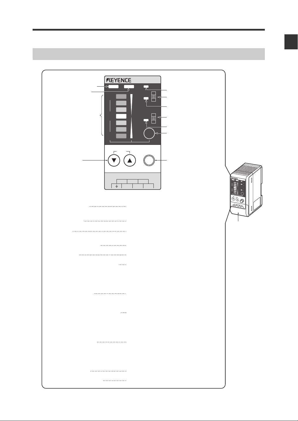
(1) Ion balance indicator Lights when the charged level of the target object is
displayed.
(2) Ion level indicator Lights when the ion emission level is being displayed.
(3) Ion monitor Indicates the charged level of the target object. Also,
indicates the ion emission level.
(4) Ion balance adjustment key Used for adjusting the ion balance.
(5) Alarm indicator Blinks when an alarm occurs.
(6) Ion level alarm sensitivity setup switch Changes the threshold at which the ion level alarm is
output.
H: High sensitivity
M: Medium sensitivity
L: Low sensitivity
(7) Ion level alarm indicator Blinks when the ion emission level has fallen below
the set value due to dirt or wear of the electrode
needles.
(8) Condition alarm sensitivity setup switch Changes the threshold at which the condition alarm is
output.
H: High sensitivity
M: Medium sensitivity
L: Low sensitivity
(9) Condition alarm indicator Blinks when static elimination performance is
influenced by the instability of the installation
environment (temperature, humidity, surrounding
metal objects, etc.), for example, when ions are being
absorbed by surrounding metal objects.
(10) Display selector key Selects the ion monitor display.
(11) Fan speed adjustment knob Adjusts the fan speed.
(1) Ion balance indicator
(5) Alarm indicator
(6) Ion level alarm sensitivity
setup switch
(7) Ion level alarm indicator
(8) Condition alarm sensitivity
setup switch
(9) Condition alarm indicator
(10) Display selector key
(11) Fan speed adjustment knob
(2) Ion level indicator
(4) Ion balance
adjustment key
(3) Ion monitor
1
Controller Unit (operation/display section)
About the Static Elimination Blower Unit SJ-F100W/100/010
1-5
Page 18

1
[(3) (static elimination stop input)
+24V
3k
INPUT((3))
0V ((6))
Input a no-voltage contact (relay, etc.) or
NPN open collector to INPUT and 0V.
OUT
40 VDC
100 mA
Open collector output
[(2) (ion level alarm output), (1) (condition alarm output), (7) (alarm output)]
3.9
+24V
0V ((6))
1-3 Names and Functions of Parts
About the Static Elimination Blower Unit SJ-F100W/100/010
Controller Unit (I/O terminal section)
(1) (2) (3)
B
AL
ANCE
S
J-F
100
IO
W
N
ALAR
M
+
IO
N
LEVEL
H
M
L
0
CO
N
D
H
M
L
–
DIS
P
IO
N
BALA
N
CE
AD
JAST
FA
N
S
PE
ED
SLO
W
F
AST
C
ON
D
ITIO
N
I
ON
L
EV
EL
IN
T
ERR
U
PT
24V DC
O
V
ALAR
(4) (5) (6) (7)
M
Number Name Function
(1) Condition alarm output terminal
Outputs when static elimination performance is influenced by
instability in the installation environment.
(2) Ion level alarm output terminal Outputs when the ion emission level drops.
Static elimination stop input
(3)
terminal
(4) Ground terminal
Static elimination can be turned ON/OFF by shorting this terminal
with (6).
Be sure to connect a Class D earth (maximum resistance of 100
Ohms).
(5) DC power terminal 24 VDC ±10%
(6) 0V terminal 0V for power and 0V for I/O
(7) Alarm output terminal Outputs when an alarm occurs.
Input circuit diagram
Output circuit diagram
1-6
Page 19

Chapter 2Connection and Installation?
0123 4
Static elimination
time [Sec]
0
0.2
–0.2
0.4
0.6
0.8
1.0
1.2
Charge voltage [kV]
2-1 Before Installation
This section describes the static elimination performance of the SJ-F100W/100/010.
Before you install the SJ-F100W/100/010, fully calculate the distance between the Static Elimination
Blower Unit up to the target object and the time required for static elimination.
About Static Elimination Performance
The following shows a typical example where static is eliminated from an aluminum plate (20 pF) 150 x
150 mm square charged to +1000 V by the SJ-F100W/100/010 with the fan speed set to maximum
(FAST).
Static elimination area
The following graph shows the relationship between the time required for eliminating static from a target
object charged between +1000 to +100 V and the distance from the charged object to the Static
Elimination Blower Unit.
0 200 300100 400 500 600 mm
200 mm
1 Sec 2 Sec 3 Sec
0
SJ-F010
200 mm
Static elimination time
The following graph shows the relationship between the change in charged voltage and the time when
static is eliminated from an object charged to +1000 V installed 100 mm away from the Static Elimination
Blower Unit at maximum (FAST) fan speed.
5 Sec
4 Sec
2
Connection and Installation
2-1
Page 20

2-1 Before Installation
SJ-F010
Metal roller
Film, sheet or other
electrically charged object
OK
NG
OK
Note
Appropriate static elimination method
Pay attention to the following points to ensure that
static elimination is performed appropriately.
2
Static elimination cannot be performed
Connection and Installation
accurately at locations where the target object
is touching a metallic body (earthed body).
Eliminate static from the target body at locations
where it is not directly touching metallic bodies
(earthed body).
Static will be eliminated from only the surface
of the insulated body (film, sheet, etc.) that is
facing the Static Elimination Blower Unit.
When eliminating static from both sides of a target
body, install two SJ-F100W/100/010s as one
SJF100W/100/010 must be installed on either side
of the target body.
Install the Static Elimination Blower Unit so that it can example, for replacement
of parts and cleaning.
2-2
Page 21

Installation Precautions
CAUTION
30 mm or more
50 mm or more
SJ-F010
SJ-F010
15 mm or more
2-1 Before Installation
Installation site
Refer to the following diagram when installing the SJ-F100W/100/010.
• Install the Static Elimination Blower Unit away from the wall or surrounding
objects.
• Install the Static Elimination Blower Unit so that the Electrode Unit can be
removed for replacement.
Interference
The Static Elimination Blower Unit may not function properly if two or more units are used close to each
other. In such an installation, refer to the following diagram and maintain the indicated distance between
units.
2
Connection and Installation
2-3
Page 22

2
M4 screws
M4 tapped holes
SJ-F010
M4 screws
M4 screws
2-2 Connection and Installation
This section describes how to connect and install the Static Elimination Blower Unit and Controller Unit.
Installing the SJ-F100W/100/010
Connection and Installation
Install the SJ-F100W/100/010 at locations where static electricity is generated or is likely to be
generated.
Installing the Static Elimination Blower Unit
There are two ways of installing the Static Elimination Blower Unit, with or without the mounting fixtures.
When using mounting fixture A:
1 Tap M4 screw holes where the Static Elimination Blower Unit is to be installed, and fasten
mounting fixture A (OP-51409) with the M4 screws.
You can adjust the horizontal angle of the
Static Elimination Blower Unit by using the
semi-circled cutout holes on the base of
mounting fixture A.
The M4 screws for fastening mounting
fixture A at the installation location must
be provided separately.
2 Install the Static Elimination Blower Unit on mounting fixture A.
You can adjust the vertical angle of the Static Elimination Blower Unit by using the semi-circled
cutout holes on the base of mounting fixture A.
The M4 screws for fastening mounting fixture A to the Static Elimination Blower Unit are provided
with mounting fixture A.
2-4
Page 23

2-2 Connection and Installation
M4 screws
M4 screws
M4 tapped holes
M4
screws
M4
screws
+
–
0
B
ALA
N
C
E
ION
ION
L
E
V
E
L
C
O
N
D
FAN
S
PEED
SLOW
24V
D
C
OV
A
LA
R
M
CONDIT
IO
N
IN
T
ER
R
UPT
ION
LE
V
EL
FA
S
T
DISP
H
M
L
H
M
L
A
LA
R
M
SJ-F100W
ION
B
A
LAN
C
E
AD
J
A
ST
When using mounting fixture B:
1 Install mounting fixture B (OP-51410) on the Static Elimination Blower Unit.
M4 screws for fastening the Static
Elimination Blower Unit to mounting
fixture B are provided with mounting
fixture B.
M4
screws
SJ-F010
2 Tap M4 screw holes where the Static Elimination Blower Unit is to be installed, and fasten
mounting fixture B (OP-51410) with the M4 screws.
M4 screws for fastening mounting
fixture B to the installation location must
be provided separately.
2
Connection and Installation
M4
screws
3 Loosen the screws mounted on the Static Elimination Blower Unit, and adjust the
installation angle. Then, fasten with the screws again.
When the mounting fixture is not used:
Drill holes of diameter 4.2 mm or more at the location where the Static Elimination Blower Unit is to be
installed, and fasten with the M4 screws.
The M4 screws must be provided
separately.
Installing the Controller unit
Mount the Controller Unit on the DIN rail.
2-5
Page 24

2-2 Connection and Installation
FA
N SP
EED
SL
O
W
2
4V
DC
OV
AL
ARM
C
O
N
D
IT
IO
N
IN
T
E
R
RUP
T
IO
N
L
E
V
E
L
FA
S
T
ION B
A
LANCE
A
DJ
A
ST
Be sure to connect a
Class D earth
(maximum resistance
of 100 Ohms).
WARNING
F
A
N
S
P
E
E
D
S
L
OW
24
V
DC
OV
AL
ARM
C
ON
D
ITIO
N
IN
T
E
R
R
U
P
T
I
O
N L
E
V
E
L
FAST
IO
N BALANCE
A
DJA
S
T
Match and connect the
end of the connector
cable to the inlet on
the Controller Unit.
F
A
N
S
P
E
E
D
S
LOW
2
4V
DC
OV
AL
ARM
CO
N
D
IT
I
O
N
I
N
T
E
R
R
U
P
T
ION
L
E
V
E
L
FA
ST
ION BA
LA
NCE
A
D
JA
S
T
To 24 VDC
power supply
To 24 VDC
power supply
Connecting Cables
2
When you have finished installing the Static Elimination Blower Unit, connect the earth lead, Static
Connection and Installation
Elimination Blower Unit connector cable and power supply.
Connecting the earth lead
Open the terminal plate cover on the
Controller Unit, and connect the earth lead to
the GND connection terminal.
Be sure to connect a Class D earth
(maximum resistance of 100 Ohms).
To prevent electric shock and to ensure accurate static elimination, be sure to
connect a Class D earth (maximum resistance of 100 Ohms).
Connecting the cable
Connect the Static Elimination Blower Unit
connector cable to the Controller Unit.
Connect this cable with the power turned OFF.
When installing the Controller Unit away from
the Static Elimination Blower Unit, use the
optional extension cable (SJ-C3).
Up to 3 cables can be connected.
Connecting the power supply
Connect the power supply according to either
of the following methods.
24 VDC power supply
Connect a 24 VDC output power supply
having sufficient power capacity margin to
the power terminals (terminals (5) and (6))
"Controller Unit (I/O terminal section)"
(page 1-6)
2-6
Page 25

AC adapter (SJ-U2)
FA
N
S
PE
ED
SLOW
2
4V DC
O
V
ALAR
M
C
ON
D
I
T
I
ON
I
N
T
E
R
RUP
T
IO
N
LE
V
E
L
FA
S
T
I
O
N BA
LANCE
AD
JA
ST
Connect the AC adapter to the connector on the side of the
Controller Unit.
The AC adapter is available as an option.
2-2 Connection and Installation
2
Connection and Installation
2-7
Page 26

2
2-2 Connection and Installation
This page left intentionally blank
Connection and Installation
2-8
Page 27

Chapter 3SJ-F100W/100 /010 Functions?
3-1 Fan Speed Adjustment Function
This section describes the SJ-F100W/100/010's fan speed adjustment function.
Fan Speed Adjustment Function
Use the fan speed adjustment knob to adjust the blast from the Static Elimination Blower Unit. Setting the
fan speed to FAST enables static elimination over a wide area.
BALANCE
SJ-F100W
ION
ION BALANCE
ALARM
ION
LEVEL
H
M
L
COND
H
M
L
DISP
AD
JAST
FAN SPEED
SLOW
FAST
CO
NDITIO
N
ION
LEVE
L
IN
TER
R
UP
T
24V DC
OV
ALARM
+
0
–
ION BALANCE
ADJUST
FAN SPEED
SLOW FAST
3
SJ-F100W/100/010 Functions
3-1
Page 28

3
BALANCE
+
–
0
BALANCE
ION
ION
LEVEL
COND
DISP
ALARM
H
M
L
H
M
L
+
–
0
Red
Orange
Orange
Green
Orange
Orange
Red
Display
selector key
ION
+
–
0
BALANCE
ION
ION
LEVEL
COND
DISP
ALARM
H
M
L
H
M
L
+
–
0
Green
Green
Orange
Red
Orange
Green
Green
Max.
+ ion
– ion
Min.
Min.
Max.
Display
selector key
3-2 Ion Monitor Functions
This section describes the SJ-F100W/100/010's ion monitor functions.
Ion Monitor Functions
The charged amount of the target object and the amount of ion generated from the Static Elimination
Blower Unit are indicated on the ion monitor.
The ion monitor indication can be switched by the display selector key.
SJ-F100W/100/010 Functions
Charge monitor
This monitor indicates the charged and decharged
states of the target object.
The indication of this monitor fluctuates towards
the + and - sides according to the charged level.
The further the indication is away from the center,
the larger the charged level. When static
elimination is completed, the indication returns to
the center position so that you can easily tell how
static elimination is progressing.
The ion balance indicator lights when the charge
monitor is operating.
Ion level monitor
This monitor indicates the level of ions being
generated by the Static Elimination Blower Unit.
The amount of plus ions being generated is
indicated on the upper side, while the amount of
minus ions is indicated on the lower side. The
further the indication is away from the center, the
larger the level of ions. In a state where ions are
being sufficiently generated, both ends of this
monitor light (green).
The ion balance indicator lights when the ion level
monitor is operating.
3-2
Page 29

3-3 Alarm Output Functions
+
–
0
BALANCE
ION
ION
LEVEL
COND
DISP
ALARM
H
M
L
H
M
L
ALARM
+
–
0
BALANCE
ION
ION
LEVEL
COND
DISP
ALARM
H
M
L
H
M
L
Ion level alarm
sensitivity setup
switch
ION
LEVEL
+
–
0
BALANCE
ION
ION
LEVEL
COND
DISP
ALARM
H
M
L
H
M
L
Condition alarm
sensitivity setup
switch
COND
This section describes the SJ-F100W/100/010's alarm output functions.
Alarm Output Functions
Alarm output function (ALARM)
The alarm indicator blinks (red) and an alarm signal
(control output (N.C.)) is output, for example, when
internal circuits are damaged or abnormal discharging
occurs. When an alarm signal is output, static
elimination is forcibly stopped.
Alarm output turns ON even in a static elimination
stopped state (including forced static elimination stop).
Ion level alarm output function (ION LEVEL)
The ion level alarm indicator lights and an alarm signal
(control output (N.O.)) is output when the amount of
generated ions drops due to dirty electrode needles, for
example. When an alarm signal is output, static
elimination is not stopped.
Alarm output can be adjusted in three stages by the ion
level alarm sensitivity switch according to the amount of
ions generated.
The default setting for the ion level alarm sensitivity
switch is L (Low).
The ion level serves as a guideline for learning when to
perform maintenance on the electrode needles. As
static elimination is continued, be sure to turn the power
OFF before starting maintenance on the electrode
needles.
3
SJ-F100W/100/010 Functions
Condition alarm output function (COND)
The condition alarm output indicator lights and an alarm
signal (control output (N.O.)) is output when static
elimination performance is influenced by the installation
environment (temperature, humidity, surrounding metal
objects, etc.) or when ions are absorbed by surrounding
metal objects. When an alarm signal is output, static
elimination is not stopped.
Alarm output can be adjusted in three stages by the
condition alarm sensitivity switch according to the
installation environment.
The default setting for the condition alarm sensitivity
setup switch is L (Low).
3-3
Page 30

3
CAUTION
FAN SPEED
SLOW FAST
ION BALANCE
ADJUST
+
–
0
ION
ION
LEVEL
COND
DISP
Display
selector key
ALARM
BALANCE
H
M
L
H
M
L
Note
SJ-F100W/100/010 Functions
3-4 Other Functions
This section describes the abnormal discharge detection, ion balance adjustment and static elimination
stop functions.
Abnormal Discharge Detection Function
To prevent trouble, the generation of ions is stopped when abnormal discharging caused by
condensation on the electrode needle tips or adhesion of debris is detected.
At this time, the alarm indicator and ion monitor blink to inform you that an abnormality has occurred. For
details of the indicated state on the Controller Unit (operation/ indication section), see "During an
alarm (level 2)" (page A-6).
Ion Balance Adjustment Function
The SJ-F100W/100/010 senses the charged amount of the target object by the I.C.C. function to
automatically control the generated amount (balance) of plus and minus ions.
The zero point, the point for reference for the I.C.C. function, is adjusted before the SJF100W/100/010 is
shipped from the factory. However, in some environments, the zero point sometimes drifts. If this
reference zero point drifts, adequate static elimination cannot be maintained. For this reason, you can
adjust the SJ-F100W/100/010 to the desired zero point.
Do not turn the power OFF while the ion balance is being adjusted (about 30
seconds).
Setting the ion balance
1 Hold down the display selector key for about three seconds to start the ion balance setup.
The ion balance indicator blinks.
Holding down the display selector key for about three seconds when setting the
ion balance clears the preset ion balance zero point and returns the ion balance
to its default setting.
3-4
Page 31

Set the ion balance using the ion balance adjustment keys.
FAN SPEED
SLOW FAST
ION BALANCE
ADJUST
+
–
0
BALANCE
ION
ION
LEVEL
COND
DISP
ALARM
H
M
L
H
M
L
Ion balance
adjustment
keys
FAN SPEED
SLOW FAST
ION BALANCE
ADJUST
+
–
0
ION
ION
LEVEL
COND
DISP
ALARM
BALANCE
H
M
L
H
M
L
Display
selector key
Note
2
The LED on the ion monitor corresponding to the
set value lights.
Key Function
Key Shifts the zero point in the + direction.
Key Shifts the zero point in the - direction.
3 Press the display selector key to exit ion balance setup.
After you have finished setting up the ion balance,
the ion balance indicator will blink fast for about 30
seconds, indicating that the ion balance setup is
being written to memory.
3-4 Other Functions
3
SJ-F100W/100/010 Functions
After you have finished setting up the ion balance, do not change the ambient
environment for about 30 seconds. If you do, the zero point sometimes cannot be
set accurately.
3-5
Page 32

3
FAN SPE
ED
S
LOW
24V D
C
OV
ALARM
CO
N
D
I
T
I
O
N
INT
ER
R
U
PT
ION
L
E
V
E
L
FA
ST
IO
N
B
AL
A
NC
E
A
D
JA
ST
To 24 VCD power
supply
To 24 VCD power
supply
FAN SPEED
SLOW FAST
ION BALANCE
ADJUST
+
–
0
BALANCE
ION
ION
LEVEL
COND
DISP
ALARM
H
M
L
H
M
L
FAN SPEED
SLOW FAST
ION BALANCE
ADJUST
+
–
0
BALANCE
ION
ION
LEVEL
COND
DISP
ALARM
H
M
L
H
M
L
Ion balance
adjustment keys
SJ-F100W/100/010 Functions
3-4 Other Functions
Static Elimination Stop Function
Static elimination only can be turned OFF in a powered ON state by two methods: by shorting the static
elimination stop input and 0V terminals on the Controller Unit (I/O terminal section), or by holding down
the two ion balance adjustment keys on the Controller Unit (operation/display section) simultaneously for
about three seconds.
When static elimination stop input has been performed on the Controller Unit (operation/display section),
this state can be canceled by holding down the two ion balance adjustment keys simultaneously for about
three seconds.
For details on indication states on the Controller Unit (operation/display section) when static elimination
stop input is canceled, see "Static elimination stop input cancel (operation/ display section)" (page A-
4).
Static elimination stop input
Static elimination is stopped by either of the following methods.
By operation on the Controller Unit (I/O terminal section)
Short the static elimination stop input and 0V
terminals to stop static elimination.
The center LED of the ion monitor blinks (red).
"Controller Unit (I/O terminal section)" (page
1-6)
By operation on the Controller Unit (operation/display section)
Hold down the two ion balance adjustment keys
simultaneously for about three seconds to stop
static elimination.
3-6
The three center LEDs of the ion monitor blink
(red).
Page 33

Chapter 4Maintenance?
WARNING
4-1 About Maintenance
Maintenance must be performed periodically to ensure that the static elimination performance of the SJF100W/100/010 is fully demonstrated. Maintenance should thoroughly read the descriptions under
"Safety Precautions" (page i), and perform maintenance paying attention to the following points.
About Maintenance
• The SJ-F100W/100/010 uses high voltage. Before starting maintenance, be
sure to turn the power OFF. Failure to do so might result in electric shock or
malfunction.
• Do not directly touch the electrode needles. Take care not to touch these
needles even if the power is turned OFF. Directly touching these needles may
cause personal injury.
4
Maintenance
SJ-F010
When the SJ-F100W/100/010 is used for a long period of time, the electrode needles become dirty due
to the adhesion of dust and dirt.
If the ion level alarm indicator lights, clean the electrode needles. If the electrode needles are used in a
dirty or dusty state, the static elimination performance can no longer be fully demonstrated, resulting in
accidents or malfunction. We recommend periodically cleaning the electrode needles (as a guideline,
once every two weeks in a regular operating environment though this depends on the installation
conditions).
If cleaning the electrode needles does not improve the static elimination performance, or the ion level
alarm indicator frequently lights, replace the Electrode Unit.
4-1
Page 34

4
WARNING
SJ-F010
SJ-F010
Unlock the lock switch.
Remove the Electrode Unit.
Maintenance
4-2
When the SJ-F100W/100/010 is used for a long period of time, the electrode needles become dirty due
to the adhesion of dust and dirt.
If the electrode needles are used in a dirty or dusty state, the static elimination performance can no
longer be fully demonstrated, resulting in accidents or malfunction. Be sure to periodically perform
maintenance on the electrode needles.
Performing Maintenance on the Electrode Needles
Performing Maintenance on the Electrode Needles
• Before removing the Electrode Unit, turn the SJ-F100W/100/010 OFF.
• Do not directly touch the electrode needles with your hands. Doing so might
cause personal injury. Pay attention to this when performing maintenance on
the electrode needles.
1 Remove the Electrode Unit
Unlock the lock switch on the Static
Elimination Blower Unit, and pull out the
Electrode Unit in the direction of the arrow.
4-2
2 Clean the electrode needles.
Clean the electrode needles with a cotton
wool bud moistened with alcohol.
Page 35

Install the Electrode Unit.
Insert the Electrode Unit.
Lock the lock switch.
SJ-F010
SJ-F010
Note
3
Make sure that the lock switch on the
Static Elimination Blower Unit is unlocked,
and then insert the Electrode Unit.
Make sure that the Electrode Unit is
inserted as far as possible, and then lock
the lock switch to fasten the Electrode Unit
in place.
If cleaning the electrode needles does not improve the static elimination
performance, or the ion level alarm indicator frequently lights, a probable cause is
that the electrode needles have reached the end of their service life.
Replace the Electrode Unit.
An optional Replacement Electrode Unit (OP-51407) is available.
4-2 Performing Maintenance on the Electrode Needles
4
Maintenance
4-3
Page 36

4
4-2 Performing Maintenance on the Electrode Needles
This page left intentionally blank
Maintenance
4-4
Page 37

5-1 Timing Charts
NormallyONNormally
OFF
NormallyONForced
OFF
NormallyONNormally
OFF
Normally
ON
Forced
OFF
Normally
ON
Static elimination
stop input (terminal)
ON
OFF
Static elimination
stop input (controller)
ON
OFF
Ion emission state
Unit indicator
Emitting
No emissions
Alarm output
ON
OFF
+
–
0
BALANCE
ION
ION
LEVEL
COND
DISP
ALARM
+
–
0
BALANCE
ION
ION
LEVEL
COND
DISP
ALARM
H
M
L
H
M
L
H
M
L
H
M
L
Normal static elimination OFF
<during static elimination stop input
(via terminal)>
The center the ion monitor blinks (red).
Forced static elimination OFF
<during static elimination stop input
(via controller)>
The three sections in the center of
the ion monitor blink (red).
Max.
15 ms
Max.
1 s
Static elimination
stop input (unit)
ON
OFF
Ion emission state
Emitting
No emissions
This section provides timing charts for SJ-F100W/100/010.
Ion generation control timing chart
Chapter 5Specifications?
Indicator states when static elimination is OFF
Input response timing chart
5
Specifications
5-1
Page 38

5
Powe r
ON
OFF
Static elimination
stop input
ON
OFF
Alarm indicator
Blinking
OFF
Alarm output (N.C.)
ON
OFF
Ion emission
Emitting
No
emissions
Ion level indicator
Max. 10s
Blinking
OFF
Ion level alarm
output (N.O.)
ON
OFF
When the ion level alarm is output,
removing the cause of the alarm
can restore the normal state. One
way of restoring the normal state is
to perform maintenance on the
electrode needles.
For details on electrode needle
maintenance, see "Performing
Maintenance on the Electrode
Needles" ( page 4-2).
Powe r
ON
OFF
Static elimination
stop input
ON
OFF
Alarm indicator
Blinking
OFF
Alarm output (N.C.)
ON
OFF
Ion emission
Emitting
No
emissions
Condition indicator
Blinking
OFF
Condition alarm
output (N.O.)
ON
OFF
When the condition alarm is output,
removing the cause of the alarm
can restore the normal state. One
way of restoring the normal state is
to enhance the installation
environment.
Max. 10s
Powe r
ON
OFF
Static elimination
stop input
ON
OFF
Alarm indicator
Blinking
OFF
Alarm output (N.C.)
ON
OFF
Ion emission
Emitting
No
emissions
When the alarm is output, the
normal state can be restored by
performing one of the two available
restore methods depending on the
cause of alarm output.
For details on how to restore the
normal state, see "During an alarm
(levels 1, 2)" ( page A-6).
Max. 10s
5-1 Timing Charts
Ion level alarm output timing chart
Specifications
Condition alarm output timing chart
Alarm output timing chart
5-2
Page 39

5-2 Specifications
This section provides the specifications of the SJ-F100W/100/010.
Static Elimination Blower Unit/Controller Unit
Model
Voltage application method Variable DC
Applied voltage ±7000 V max.
Ion balance control method I.C.C. method
Static elimination time* 1.8 sec
Ion balance* ±5 V
Max. fan speed* 1.5 m/s
Max. blast 1 m
Ozone concentration 0.005 ppm max.
Control input Static elimination stop input NPN open collector or no-voltage contact signal
Control output Alarm output NPN open collector
Rating Power voltage 24 VDC ±10%
Environmental
resistance
Weight Static Elimination Blower Unit Approx. 350 g
* Values obtained by measurement 200 mm from the front of the Static Elimination Blower Unit
Static Elimination Blower Unit SJ-F010
Controller Unit SJ-F100W/100
3
/min
Ion level alarm output
Condition alarm output
Current consumption 450 mA max.
Operating ambient temperature 0 to +50°C
Operating ambient humidity 35 to 65%RH (condensation not allowed)
Controller Unit Approx. 250 g
100 mA (40 V max.)
AC Adapter
5
Specifications
Model SJ-U2
Rating Rated input 100 to 240 VAC (50/60 Hz)
Rated output 24 VDC 2.65 A
Environmental
resistance
Weight Approx. 250 g
Operating ambient temperature 0 to +35°C
Operating ambient humidity 20 to 80% (condensation not allowed)
5-3
Page 40

5
2x2 M4 to depth 6
6 mm dia. cable length 300 mm,
min. bend radius 15
106
(121.5)
130
120
121
ø15
59
(4.4)
45
22
35
3
36.5
11.5
11.5
5-3 External Dimensions
This section presents external dimensions for the SJ-F100W/100/010.
Body
Static Elimination Blower Unit (SJ-F010)
Specifications
5-4
Page 41

5-3 External Dimensions
50
120
5
70
32
36
46
76
8
t=2.3
4.5
9
16
5.5
40
4.5
5.5
42.5
58
60
40˚
4.5
25
50
50
109
121
2.3
30˚
26
76.5
R35
ø5
Controller Unit (SJ-F100W/100)
Mounting fixture
Mounting fixture A (OP-51409) Mounting fixture B (OP-51410)
5
Specifications
5-5
Page 42

5
6 mm dia.
cable length 3 m
49
ø15.5
51
ø15
5-3 External Dimensions
Extension cable (SJ-C3)
AC adapter (SJ-U2)
ø16
1800
(16.3)
ø3.5
50.5
(10.3)
114.5
(37.5)
7
Specifications
(12.5)
* For details of the AC cable, contact the KEYENCE sales office in your district.
(14)
28
5-6
Page 43

AAppendices?
1 Troubleshooting
This appendix describes trouble that may occur during use of the SJ-F100W/100/010 and how to remedy
this trouble. Check the following table before sending in your SJ-F100W/100/010 for repair.
Symptom Check Item Remedy
No indication on ion
monitor
Static elimination is
not performed.
Static elimination is
not performed
properly.
The ion level alarm is
output/indicated.
The condition alarm is
output/indicated.
The alarm indicator
lights.
Control output is not
output correctly.
Static elimination stop
input is not input
correctly.
Do not know meaning
of indicators.
Is the power cable connected properly? Connect the power cable correctly.
Is a power supply within specification being
used?
Are the electrode needles worn or dirty? Perform maintenance on the electrode
Is static elimination stop currently set? Cancel static elimination stop input on
Is the abnormal discharge detection function
operating?
Are conductors or other static eliminators
located nearby the Static Elimination
Blower?
Are the electrode needles worn or dirty? Perform maintenance on the electrode
Are conductive objects located within 50 mm
in front of the electrode needles?
Are conductors or other static eliminators
located nearby the Static Elimination
Blower?
Are the electrode needles worn or dirty? Perform maintenance on the electrode
- Check "During an alarm (levels 1,
Is output wired correctly? Check the output circuit and wiring,
Is input wired correctly? Check the input circuit and wiring, and
- Check "Table of Indicated States"
Use a power supply that is within
specification.
needles or replace the Electrode Unit.
the SJ-F100W/100/010.
Check the Electrode Unit for any
conductive substances (e.g. oil
droplets).
Move the Static Elimination Blower
away from conductors or other static
eliminators nearby.
needles or replace the Electrode Unit.
Remove any conductive objects from
within 50 mm in front of the Static
Elimination Blower.
Move the Static Elimination Blower
away from conductors or other static
eliminators nearby.
needles or replace the Electrode Unit.
2)" (page A-6) in this Instruction
Manual.
and connect correctly.
connect correctly.
(page A-2) in this Instruction Manual.
Appendices
A-1
Page 44

Appendices
+
–
0
BALANCE
ION
ION
LEVEL
COND
DISP
ALARM
+
–
0
BALANCE
ION
ION
LEVEL
COND
DISP
ALARM
H
M
L
H
M
L
H
M
L
H
M
L
The ion monitor LEDs fluctuate
upward and downward.
2 Table of Indicated States
This appendix describes the various indicated states of the SJ-F100W/100/010.
Indicated states when the power is turned ON
Lit State Description
The state (charged level indication or ion
level indication) that was active before
the power was turned OFF is displayed.
At the same time, the alarm indicator, ion
level alarm indicator, and condition alarm
indicator light (red).
When the power is turned ON, the indicated state (charged level
indication or ion level indication) that was active before the power
was turned OFF is displayed. Also, the alarm indicator, ion level
alarm indicator and condition alarm indicator light (red) at the
same time. After this indication state continues for about two
seconds, the ion monitor LEDs fluctuate upward and downward,
and static elimination is then started. After static elimination star ts,
the charged level or ion level is indicated.
A-2
Page 45

2 Table of Indicated States
+
–
0
BALANCE
ION
ION
LEVEL
COND
DISP
ALARM
H
M
L
H
M
L
+
–
0
BALANCE
ION
ION
LEVEL
COND
DISP
ALARM
H
M
L
H
M
L
+
–
0
BALANCE
ION
ION
LEVEL
COND
DISP
ALARM
H
M
L
H
M
L
+
–
0
BALANCE
ION
ION
LEVEL
COND
DISP
ALARM
H
M
L
H
M
L
Indicated states when settings are changed or confirmed, and during
operation (excluding when power is turned ON)
Lit State Description
One of the ion monitor LEDs and the ion
balance indicator light (red).
Charged level indication
This indicates the charged level of the target object. When there is
a plus charged object, the LEDs on the upper side (+ side) light,
and when there is a minus charged object, the LEDs on the lower
side (- side) light according to the charged level.
One each of the plus and minus side
LEDs of the ion monitor, and the ion level
indicator light (red).
Charged level indication or ion level
indication
The center LED of the ion monitor blinks
(red).
Ion level indication
This indicates the level of ions that are being generated by the SJF100W/100/010.
Display selection
The display switches to the charged level indication when the
display selector key is pressed while the ion level is indicated.
When the charged level is indicated, the display switches to the
ion level indication.
Static elimination stop input (I/O terminal section)
The center LED of the ion monitor blinks (red) when the static
elimination stop input and 0V terminals are shorted to stop static
elimination.
Appendices
A-3
Page 46

2 Table of Indicated States
+
–
0
BALANCE
ION
ION
LEVEL
COND
DISP
ALARM
H
M
L
H
M
L
+
–
0
BALANCE
ION
ION
LEVEL
COND
DISP
ALARM
H
M
L
H
M
L
+
–
0
ION
ION
LEVEL
COND
DISP
ALARM
BALANCE
H
M
L
H
M
L
+
–
0
BALANCE
ION
ION
LEVEL
COND
DISP
ALARM
H
M
L
H
M
L
Lit State Description
The three center LEDs of the ion monitor
blink (red).
Static elimination stop input (operation/display section)
The three center LEDs of the ion monitor blink (red) when the two
ion balance adjustment keys are pressed and held down at the
same time for about three seconds to stop static elimination.
Appendices
The state (charged level indication or ion
level indication) that was active before
static elimination stop input is displayed.
The ion balance indicator blinks.
One of the ion monitor LEDs lights.
Static elimination stop input cancel (operation/ display
section)
Static elimination stop input is canceled when the static
elimination stop input signal is input from the Controller Unit
(operation/display section) and the two ion balance adjustment
keys are both held down for about three seconds. When this
operation is performed, the state (charged level indication or ion
level indication) that was active before static elimination stop input
is returned to.
Note, however, that in an alarm state, the LEDs blink according to
the cause of the alarm.
For details on how to input static elimination stop from the
Controller Unit (operation/display section), see "Static
elimination stop input (operation/display section)" (page A-4).
For details on the display when an alarm occurs, see "During
an alarm (levels 1, 2)" (page A-6).
Start ion balance manual setup
Ion balance manual setup is started and the ion balance indicator
blinks by holding down the display selector key for about three
seconds.
Ion balance manual setup
During ion balance manual setup, press the ion balance
adjustment key to set the zero point.
During this operation, the LED on the ion monitor
corresponding to the set value lights.
For details on how to start ion balance manual setup, see
"Start ion balance manual setup" (page A-4).
A-4
Page 47

Lit State Description
+
–
0
BALANCE
ION
ION
LEVEL
COND
DISP
ALARM
H
M
L
H
M
L
+
–
0
ION
ION
LEVEL
COND
DISP
ALARM
BALANCE
H
M
L
H
M
L
+
–
0
BALANCE
ION
ION
LEVEL
COND
DISP
ALARM
H
M
L
H
M
L
+
–
0
BALANCE
ION
ION
LEVEL
COND
DISP
ALARM
H
M
L
H
M
L
The LEDs shift towards both ends of the
ion monitor.
The ion balance indicator blinks fast.
2 Table of Indicated States
Ion balance manual setup initialized
If the display selector key is held down for three seconds during
ion balance manual setup, the manual settings are initialized and
the LEDs of the ion monitor shift towards both ends of the ion
monitor.
End ion balance manual setup
Pressing the display selector key after ion balance manual setup
completes the setup and starts writing of the setup information to
memory. During this operation, the ion balance indicator blinks
fast for 30 seconds. After writing of setup information has ended,
the state (charged level indication or ion level indication) that was
active before manual setup is returned to.
For details on how to start ion balance manual setup, see
"Start ion balance manual setup" (page A-4).
Appendices
One of the ion monitor LEDs blinks. Ion balance manual setup confirmation
If the device is not in an ion balance manual setup state, you can
confirm the ion balance manual setup by pressing either of the ion
balance adjustment keys. During confirmation, the ion monitor
LEDs blink in one of the following three colors:
Orange: The LED blinks (orange) at the position
corresponding the setup state when ion balance
manual setup is being performed. (Sometimes the
center LED also is lit.)
Red: The LED at the edge of the side (+ or -) that was set
blinks (red) when the set value was set to MAX
during ion balance manual setup.
Green: The center LED blinks (green) for the duration that
the ion balance adjustment key is held down when
ion balance manual setup is not being performed.
The condition alarm indicator lights (red).
Condition alarm
The condition alarm indicator lights (red) when the ion balance
has deteriorated influenced by the installation environment.
A-5
Page 48

2 Table of Indicated States
+
–
0
BALANCE
ION
ION
LEVEL
COND
DISP
ALARM
H
M
L
H
M
L
+
–
0
BALANCE
ION
ION
LEVEL
COND
DISP
ALARM
H
M
L
H
M
L
+
–
0
BALANCE
ION
ION
LEVEL
COND
DISP
ALARM
H
M
L
H
M
L
Lit State Description
The ion level alarm indicator lights (red).
Ion level alarm
The ion level alarm indicator lights (red) when the generated ion
level falls below the preset level.
Appendices
The alarm indicator and the three center
LEDs of the ion monitor blink (red)
alternately.
The alarm indicator and the seven ion
monitor LEDs of the ion monitor blink
(red).
During an alarm (level 1)
The alarm indicator and the three center LEDs of the ion monitor
blink (red) alternately in the following instances.
Remedy the cause of the alarm, and simultaneously hold down
the two ion balance adjustment keys for about three seconds. This
cancels the alarm state, and executes the power ON sequence.
Probable causes of alarms
• The Electrode Unit is not connected.
• The lock switch on the Static Elimination
Blower Unit is at the unlocked position.
• The fan has stopped operating.
• Cables are disconnected or broken.
During an alarm (level 2)
The alarm indicator and seven LEDs of the ion monitor blink (red)
alternately in the following instances.
Remedy the cause of the alarm, and turn the power ON again.
If this alarm frequently re-occurs, contact your agent.
Probable causes of alarms
• Abnormal discharge
• Internal circuit damage
A-6
Page 49

3 List of Options
This appendix lists the various options available for the SJ-F100W/100/010.
Item Model External Appearance Description
Mounting fixture A OP-51409 This mounting fixture is used for mounting
the Static Elimination
Blower Unit. This fixture is provided with
four M4 screws for mounting the Static
Elimination Blower Unit.
Mounting fixture B OP-51410 This mounting fixture is used for mounting
Replacement
electrode unit
Extension cable SJ-C3 This 3 m extension cable is used for
AC adapter SJ-U2 AC adapter
OP-51407 Electrode Unit made of tungsten
the Static Elimination
Blower Unit. This fixture is provided with
four M4 screws for mounting the Static
Elimination Blower Unit.
extending the connection between the
Controller Unit and the Static Elimination
Blower Unit.
(Up to 3 cables can be connected.)
* For details of the AC cable, contact the
KEYENCE sales office in your district.
Appendices
A-7
Page 50

4 Index
This is an index of the main terms used in this manual.
Appendices
Numerics
0V terminal ........................................................ 1-6
A
Abnormal Discharge Detection Function .....1-2, 3-4
About Maintenance
............................................ 4-1
Performing Maintenance on the Electrode
Needles
AC adapter
Alarm indicator
Alarm Output Functions
Alarm output functions
Condition alarm output function
Ion level alarm output function
Alarm output terminal
...................................................... 4-2
........................................................A-7
................................................... 1-5
...............................1-2, 3-3
..........................1-2, 3-3
............1-2, 3-3
.............1-2, 3-3
........................................ 1-6
C
Charge monitor .................................................. 3-2
Charged level indication
Condition alarm
.................................................A-5
Condition alarm indicator
Condition alarm output function
Condition alarm output terminal
Condition alarm sensitivity setup switch
Connecting Cables
Controller Unit (I/O terminal section)
Controller Unit (operation/display section)
....................................A-3
................................... 1-5
...................1-2, 3-3
......................... 1-6
............ 1-5
............................................ 2-6
................. 1-6
......... 1-5
D
DC power terminal ............................................. 1-6
Display selection
Display selector key
During an alarm (level 1)
During an alarm (level 2)
................................................ A-3
........................................... 1-5
................................... A-6
................................... A-6
E
Electrode needle ................................................ 1-4
Electrode Unit
Extension cable
Extension cable (SJ-C3)
External Dimensions
AC adapter (SJ-U2)
Controller Unit (SJ-F100W/100)
Extension cable (SJ-C3)
Mounting fixture A (OP-51409)
Mounting fixture B (OP-51410)
Static Elimination Blower Unit (SJ-F010)
.................................................... 1-4
.................................................A-7
.................................... 5-6
.......................................... 5-4
.................................... 5-6
................. 5-5
............................. 5-6
................... 5-5
................... 5-5
... 5-4
F
Fan guard ...........................................................1-4
Fan Speed Adjustment Function
Fan speed adjustment knob
.................1-1, 3-1
...............................1-5
G
Ground terminal ..................................................1-6
I
I.C.C. (Ion Current Control) method ...................1-1
I/O terminal section
Indicated states when the power is turned ON
Input circuit diagram
Input response timing chart
Installation site
Installing the SJ-F100W/100/010
Interference
Ion Balance Adjustment Function
Ion balance adjustment key
Ion balance indicator
Ion balance manual setup
Ion level alarm
Ion level alarm indicator
Ion level alarm output function
Ion level alarm output terminal
Ion level alarm sensitivity setup switch
Ion level indication
Ion level indicator
Ion level monitor
Ion Monitor Function
Charge monitor
Ion level monitor
............................................1-6
.. A-2
...........................................1-6
................................5-1
....................................................2-3
.......................2-4
........................................................2-3
................1-2, 3-4
................................1-5
..........................................1-5
................................. A-4
................................................... A-6
.....................................1-5
....................1-2, 3-3
...........................1-6
...............1-5
............................................. A-3
...............................................1-5
.................................................3-2
....................................1-2, 3-2
....................................1-2, 3-2
...................................1-2, 3-2
L
List of Options ................................................... A-7
AC adapter (SJ-U2)
Extension cable (SJ-C3)
Mounting fixture A (OP-51409)
Mounting fixture B (OP-51410)
Replacement electrode unit (OP-51407)
Lock switch
.........................................................1-4
Low voltage power-saving wiring
.................................... A-7
............................ A-7
.................. A-7
.................. A-7
.... A-7
.......................1-2
M
metallic body (earthed body) ..............................2-2
Mounting fixture A (OP-51409)
Mounting fixture B (OP-51410)
................... 1-3, A-7
................... 1-3, A-7
A-8
Page 51

4 Index
N
Names and Functions of Parts .......................... 1-4
O
OP-51407 ...................................................1-3, A-7
OP-51409
OP-51410
Outline of the SJ-F100W/100/010
Output circuit diagram
................................................... 1-3, A-7
................................................... 1-3, A-7
..................... 1-1
Abnormal discharge detection function
Alarm output functions
Fan speed adjustment function
I.C.C. (Ion Current Control) method
Ion balance adjustment function
Ion monitor function
Low voltage power-saving wiring
Static elimination stop function
Variable DC method
................................ 1-2
.................. 1-1
........... 1-1
................. 1-2
.................................... 1-2
............... 1-2
................... 1-2
................................... 1-1
....................................... 1-6
...... 1-2
P
Package Contents ............................................. 1-3
Performing Maintenance on the Electrode
Needles
Power indicator
Precautions on Regulations and Standards
............................................................. 4-2
.................................................. 1-4
....... viii
Static elimination stop input cancel
(operation/ display section)
Static elimination stop input terminal
Static elimination time
............................... A-4
..................1-6
........................................2-1
T
Table of Indicated States ................................... A-2
Terminal plate cover
Timing Charts
Troubleshooting
...........................................1-5
.....................................................5-1
................................................. A-1
V
Variable DC method ...........................................1-1
W
Warning Label ....................................................... ii
Z
zero point ............................................................3-4
Appendices
R
Replacement Electrode Unit .......................1-3, A-7
S
Setting the ion balance ...................................... 3-4
SJ-C3
.................................................................A-7
SJ-F010
SJ-F100W/100
SJ-U2
Specifications
Static elimination area
Static Elimination Blower Unit
static elimination method
Static Elimination Performance
Static Elimination Stop Function
Static elimination stop input
(I/O terminal section)
Static elimination stop input
(operation/display section)
............................................................. 1-3
................................................... 1-3
.................................................................A-7
.................................................... 5-3
....................................... 2-1
............................ 1-4
Electrode needle
Electrode Unit
Fan guard
Lock switch
Power indicator
........................................ 1-4
............................................. 1-4
................................................... 1-4
................................................. 1-4
........................................... 1-4
................................... 2-2
......................... 2-1
..................1-2, 3-6
.........................................A-3
.................................A-4
A-9
Page 52

Revision History
Printing Date Version Revision Details
October 2009 Official release
November
2010
2nd edition A description of AC adapter"SJ-U1" was changed to a descrip-
tion of AC adapter"SJ-U2".
Page 53

MEMO
Page 54

MEMO
Page 55

WARRANTIES AND DISCLAIMERS
(1) KEYENCE warrants the Products to be free of defects in materials and workmanship for a period of one (1)
year from the date of shipment. If any models or samples were shown to Buyer, such models or samples were
used merely to illustrate the general type and quality of the Products and not to represent that the Products
would necessarily conform to said models or samples. Any Products found to be defective must be shipped to
KEYENCE with all shipping costs paid by Buyer or offered to KEYENCE for inspection and examination. Upon
examination by KEYENCE, KEYENCE, at its sole option, will refund the purchase price of, or repair or replace
at no charge any Products found to be defective. This warranty does not apply to any defects resulting from
any action of Buyer, including but not limited to improper installation, improper interfacing, improper repair,
unauthorized modification, misapplication and mishandling, such as exposure to excessive current, heat,
coldness, moisture, vibration or outdoors air. Components which wear are not warranted.
(2) KEYENCE is pleased to offer suggestions on the use of its various Products. They are only suggestions, and it
is Buyer's responsibility to ascertain the fitness of the Products for Buyer’s intended use. KEYENCE will not be
responsible for any damages that may result from the use of the Products.
(3) The Products and any samples ("Products/Samples") supplied to Buyer are not to be used internally in
humans, for human transportation, as safety devices or fail-safe systems, unless their written specifications
state otherwise. Should any Products/Samples be used in such a manner or misused in any way, KEYENCE
assumes no responsibility, and additionally Buyer will indemnify KEYENCE and hold KEYENCE harmless from
any liability or damage whatsoever arising out of any misuse of the Products/Samples.
(4) OTHER THAN AS STATED HEREIN, THE PRODUCTS/SAMPLES ARE PROVIDED WITH NO OTHER
WARRANTIES WHATSOEVER. ALL EXPRESS, IMPLIED, AND STATUTORY WARRANTIES, INCLUDING,
WITHOUT LIMITATION, THE WARRANTIES OF MERCHANTABILITY, FITNESS FOR A PARTICULAR
PURPOSE, AND NON-INFRINGEMENT OF PROPRIETARY RIGHTS, ARE EXPRESSLY DISCLAIMED. IN
NO EVENT SHALL KEYENCE AND ITS A FFILIATED ENTITIES BE LIABLE TO ANY PERSON OR ENTITY
FOR ANY DIRECT, INDIRECT, INCIDENTAL, PUNITIVE, SPECIAL OR CONSEQUENTIAL DAMAGES
(INCLUDING, WITHOUT LIMITATION, ANY DAMAGES RESULTING FROM LOSS OF USE, BUSINESS
INTERRUPTION, LOSS OF INFORMATION, LOSS OR INACCURACY OF DATA, LOSS OF PROFITS,
LOSS OF SAVINGS, THE COST OF PROCUREMENT OF SUBSTITUTED GOODS, SERVICES OR
TECHNOLOGIES, OR FOR ANY MATTER ARISING OUT OF OR IN CONNECTION WITH THE USE OR
INABILITY TO USE THE PRODUCTS, EVEN IF KEYENCE OR ONE OF ITS AFFILIATED ENTITIES WAS
ADVISED OF A POSSIBLE THIRD PARTY’S CLAIM FOR DAMAGES OR ANY OTHER CLAIM AGAINST
BUYER. In some jurisdictions, some of the foregoing warranty disclaimers or damage limitations may not
apply.
BUYER'S TRANSFER OBLIGATIONS:
If the Products/Samples purchased by Buyer are to be resold or delivered to a third party, Buyer must provide
such third party with a copy of this document, all specifications, manuals, catalogs, leaflets and written
information provided to Buyer pertaining to the Products/Samples.
E 1110-2
Page 56

Copyright (c) 2009 KEYENCE CORPORATION. All rights reserved. 10735E 1120-2 96M10750 Printed in Japan
 Loading...