

Page 1
NEW
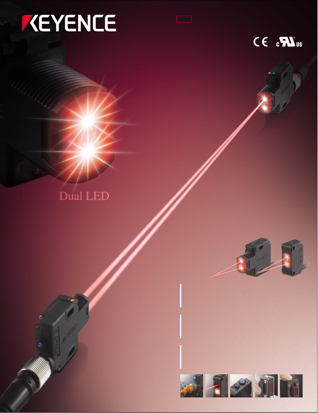
Self-contained Threaded Sensors
PZ-G Series
MEGA POWER
Long-range detection twice as far as
conventional models
EAS Y AD JUSTMENT
The front light-receiving indicator allows
easy optical axis alignment
EASY INSTALLATION
A one-touch mounting bracket makes
screws unnecessary
Page 2
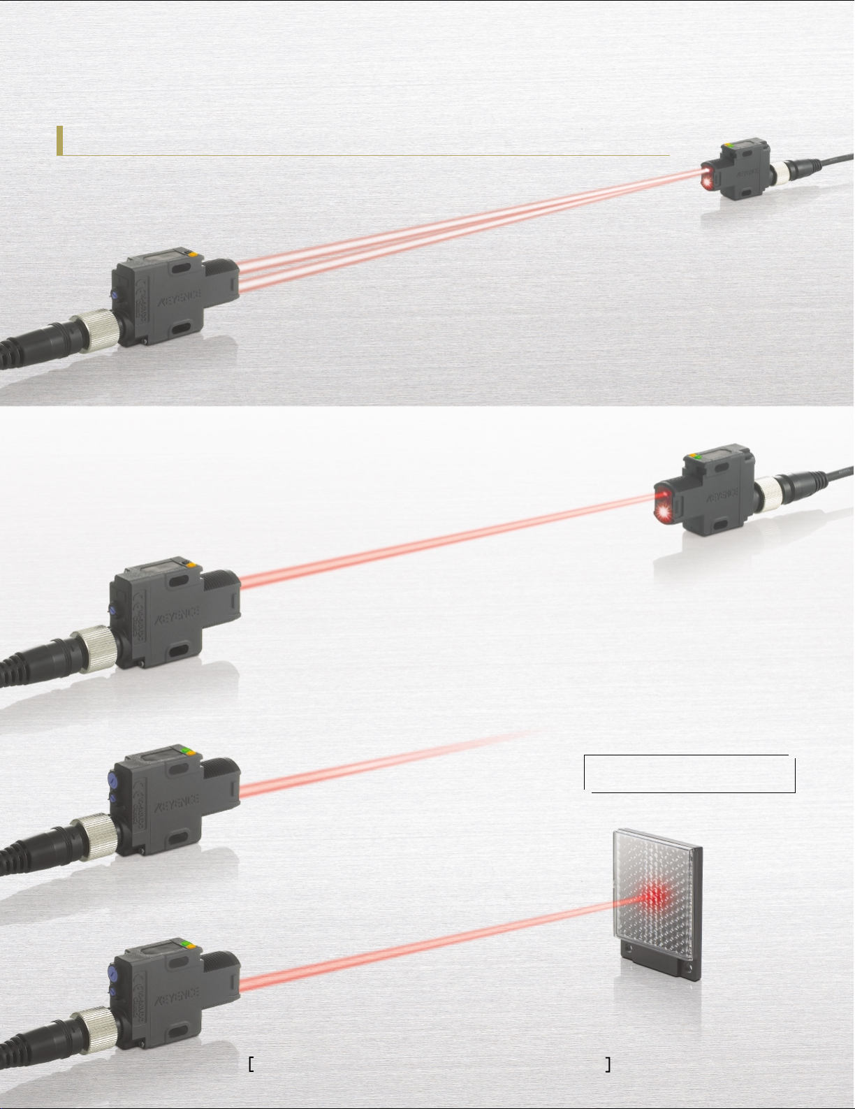
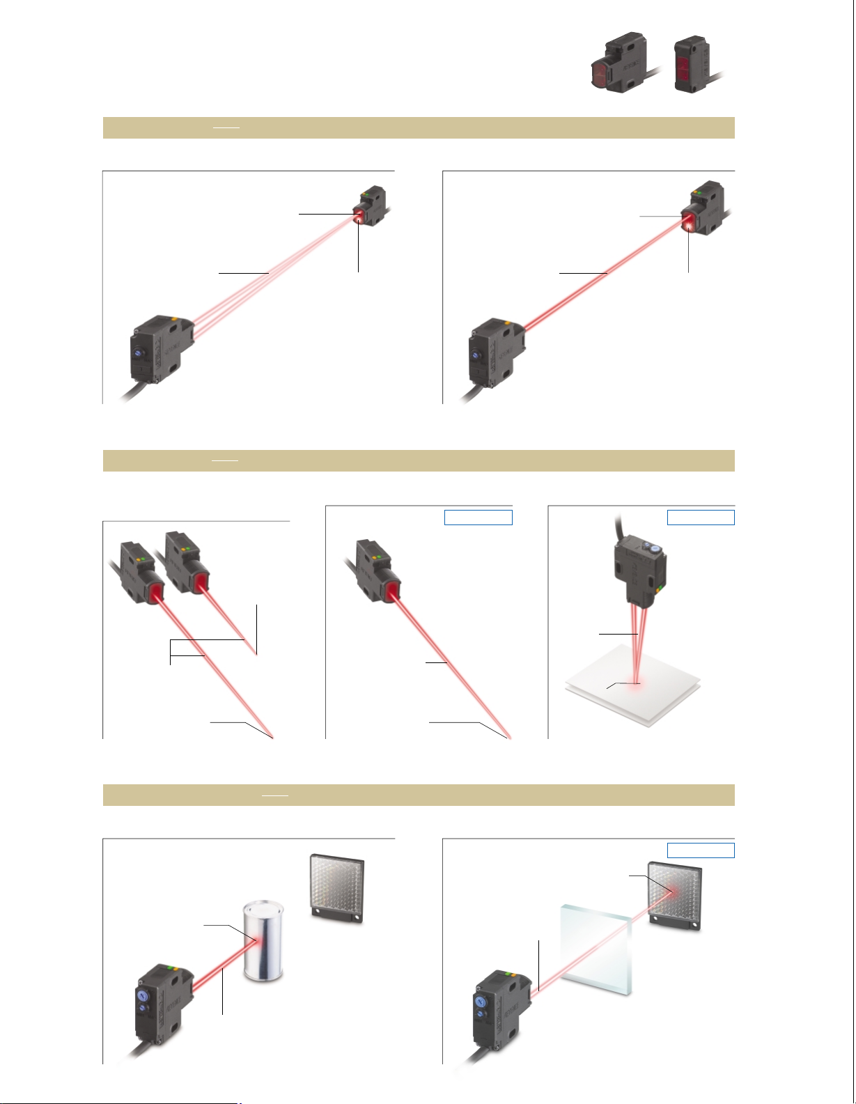
Dramatically improved performance and ease-of-use
MEGA POWER
High-Power Dual LED-type
High-power thrubeam type PZ-G52
4-element red LED-type
Thrubeam type PZ-G51
Detecting distance:
Detecting distance:
40 m
20m
(
131.2’
(
65.6’
)
4
times
longer detecting distance
2
times
faster response speed
*
*
* Compared with our conventional models
)
2
times
longer detecting distance
*
Reflective type PZ-G41
Retro-reflective type PZ-G61
Detecting distance:
Detecting distance:
(
1m
3.3’
4.2m
)
(
13.8’
*
2
times
faster response speed
The high-intensity 4-element red LED has
greatly improved the detecting distance.
The bright beam spot makes it easy to
align the optical axis.
A 4-element LED is used in upper-level fiber sensors
because its wavelength can be easily observed by the
human eye and the intensity change over time is small.
* Compared with our conventional models
)
Self-contained Threaded Sensors PZ
2
-
G Series
Page 3
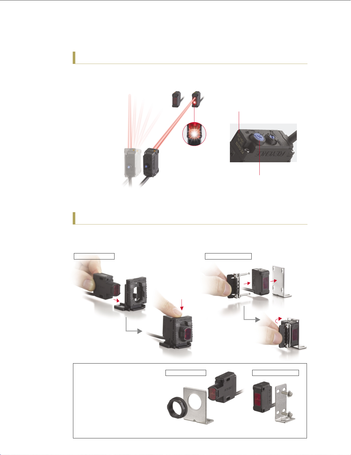
EA SY ADJU STMENT
Alignment indicator takes the guesswork
out of long distance sensor setup
Has your receiver
been bumped out of
alignment? How can
you tell?
Thrubeam PZ-G
models feature a bright
red LED indicator that
alerts you the instant
proper alignment has
been obtained. This
simple yet crucial
feature allows you to
troubleshoot setup and
run-time issues
quickly, before they
can snowball into
major problems.
Laser Marked tags eliminate
possible contamination
All information (model#, lot#, etc.) is laser
marked directly onto the sensor housing.
There are no labels, inks or paints to peel
or chip off into your products.
Easy-to-see blue trimmer
Enhances operation efficiency
EASY INSTALLATION
One-Touch mounting brackets cut installation time
Our unique one-touch brackets can save you and your customers considerable man-hours
during installation or replacement.
Threaded models
Slide it through
Rectangular models
Slide it through
A variety of mounting
styles are available to
adapt to your application.
Just push
until it clicks
Threaded models
Can be attached
with an M18 nut
Just push
until it clicks
Rectangular models
Can be attached
with two M3 screws
3
Page 4
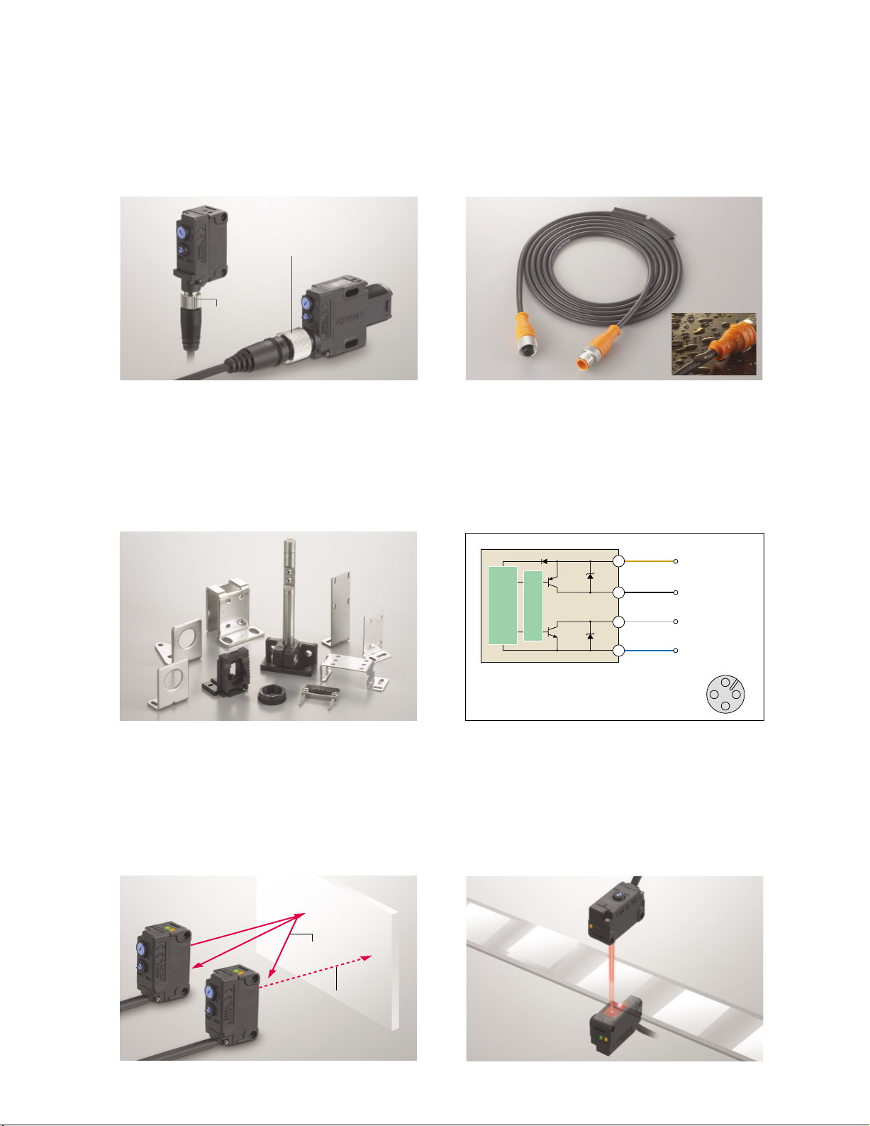
Enhanced user-friendliness Model features
Standard M8 and M1 2 q uick -disconnects
make replacement easier
The PZ-G features a standard pin-out, which allows it to be
a drop-in replacement with existing wiring.
Threaded type
M12 connector
Rectangular type
M8 connector
19 types of mounting brackets provide
a variety of mounting methods
A bracket can be selected according to the installation
conditions. 19 types, including a one-touch bracket, are
available.
Our oil-resistant cable ensures reliable
operation in an oily environment
In addition to the standard PVC cable, an oil-resistant PUR
cable is available for use in harsh environments.
PUR cable
Bipolar output (NPN+PNP) compatible
with any input device
Threaded models feature bipolar output (NPN and PNP),
eliminating the need to stock sensors for both outputs.
The mounting brackets shown above are only part of the lineup.
See page 7 for further details.
The interference suppression function
prevents interference from nearby units
With thrubeam models, up to two sensors can be mounted
in close proximity. Four sensors can be used by alternating
the transmitter/ receiver position.
Ambient light
Overcurrent
protection circuit
Sensor main circuit
Bipolar output type
PZ-G**(C)B
Brown (Pin1)
Black (Pin 4)
White (Pin 2)
Blue (Pin 3)
DC10−30V
PNP control output
NPN control output
0V
M12 connector
2
3
1
4
High-speed targets can be detected
at a response speed of up to 500 s
A high-speed response of up to 500 s, twice as fast as our
conventional models, ensures detection on a high-speed line.
The high power ensures stable detection.
Different frequency beam
Differentiating the
number of sheets
The different frequency function automatically shifts the emission cycle if ambient
light is received by the receiver.
4
Page 5
Rectangular modelsThreaded models
Thrubeam
The long-range high-power beam makes it easy to align the optical axis
Long-range detection
40m (131.2’)
High-power
dual IR LED
Reflective
Diffuse reflective PZ-G41
PZ-G42
The visible spot makes it easy to align the optical axis
(long-range)
(short-range)
Standard PZ-G51High-power PZ-G52
High-intensity
Alignment
4-element red LED
Indicator
Clearly indicates when
emitter/receiver are
properly aligned.
Narrow-view reflective type PZ-G101
Coming soon Coming soon
Long-range detection
20m (65.6’)
Alignment
Indicator
Clearly indicates when
emitter/receiver are
properly aligned.
Thrubeam
Definite reflective type PZ-G102
Short-range
detection
300mm
(11.81")
High-intensity
High-intensity
4-element red LED
Long-range detection
1m (3.3’)
Retro-reflective
Standard PZ-G61 (with P. R. O. function) Transparent object detection type PZ-G62
High-power long-range detection
4-element red LED
Spot diameter of
approx.
5 mm (0.20") at a
detecting distance of
100 mm (3.94")
Short-range
detection
200mm
(7.87")
Detecting distance
High-intensity
4-element
red LED
Detecting
distance of
5 to 45 mm
(0.20" to 1.77")
Spot diameter of
approx. 2 mm (0.08") at a
detecting distance of
40 mm (1.58")
Coming soon
0.1 to 1 m (0.3’ to 3.3’)
Long-range detection
(When using R-2L)
0.1 to 4.2 m
(0.3’ to 13.8’)
(When using R-2L)
Single IR LED
High-intensity
4-element red LED
P.R.O. function
The P. R. O. function*
cancels direct
reflections from metallic
or mirror surfaced
targets, allowing the
PZ-G to reliably detect
metal targets.
* Polarized Reflection Optics
DEX circuit
The PZ-G employs a DEX circuit*
(patented) that greatly amplifies the slight
light attenuation caused by transparent
targets ensuring stable detection.
* Difference Expansion
5
Page 6
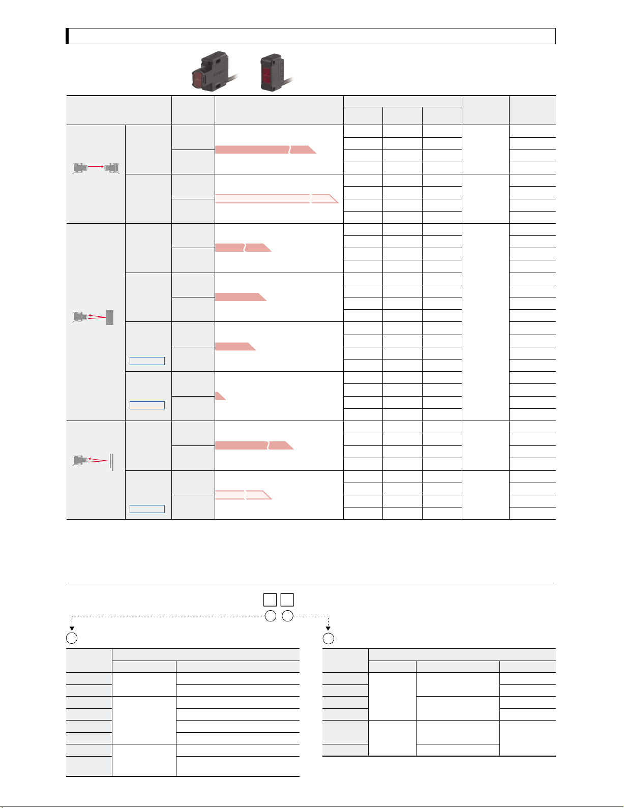
Sensor head lineup / Model variations
Sensor head lineup
Type
Standard
Thrubeam
Highpower
Diffuse
reflective
long-range
Diffuse
reflective
short-range
Reflective
Retroreflective**
*Cable sold separately for connector models **Reflector sold separately
Narrowview
reflective
Coming soon
Difinite
reflective
Coming soon
Longrange
(with P. R. O.
function)
Transparent
object
detection
Coming soon
Design
Rectangular
Threaded
Rectangular
Threaded
Rectangular
Threaded
Rectangular
Threaded
Rectangular
Threaded
Rectangular
Threaded
Rectangular
Threaded
Rectangular
Threaded
Threaded
models
Detecting distance
1 m (3.3’)
300 mm (11.81")
200 mm (7.87")
5 to 45 mm (0.20" to 1.77")
0.1 to 4.2 m (0.3’ to 13.8’)
0.1 to 1 m (0.3’ to 3.3’)
(when using R-2L)
Rectangular
models
20 m (65.6’)
40 m (131.2’)
(when using R-2L)
Model variations
NPN PNP
Bipolar
(NPN+PNP)
―PZ-G51PPZ-G51N
―PZ-G51CPPZ-G51CN
PZ-G51B――
PZ-G51CB――
―PZ-G52PPZ-G52N
―PZ-G52CPPZ-G52CN
PZ-G52B――
PZ-G52CB――
―PZ-G41PPZ-G41N
―PZ-G41CPPZ-G41CN
PZ-G41B――
PZ-G41CB――
―PZ-G42PPZ-G42N
―PZ-G42CPPZ-G42CN
PZ-G42B――
PZ-G42CB――
―PZ-G101PPZ-G101N
―PZ-G101CPPZ-G101CN
PZ-G101B――
PZ-G101CB――
―PZ-G102PPZ-G102N
―PZ-G102CPPZ-G102CN
PZ-G102B――
PZ-G102CB――
―PZ-G61PPZ-G61N
―PZ-G61CPPZ-G61CN
PZ-G61B――
PZ-G61CB――
―PZ-G62PPZ-G62N
―PZ-G62CPPZ-G62CN
PZ-G62B――
PZ-G62CB――
Light source
(LED)
Red
Infrared x 2
Red
Red
Infrared
Cable*
Cable (2m 6.6’)
M8 connector
Cable (2m 6.6’)
M12 connector
Cable (2m 6.6’)
M8 connector
Cable (2m 6.6’)
M12 connector
Cable (2m 6.6’)
M8 connector
Cable (2m 6.6’)
M12 connector
Cable (2m 6.6’)
M8 connector
Cable (2m 6.6’)
M12 connector
Cable (2m 6.6’)
M8 connector
Cable (2m 6.6’)
M12 connector
Cable (2m 6.6’)
M8 connector
Cable (2m 6.6’)
M12 connector
Cable (2m 6.6’)
M8 connector
Cable (2m 6.6’)
M12 connector
Cable (2m 6.6’)
M8 connector
Cable (2m 6.6’)
M12 connector
Model variations
PZ-G
2
1
Detection method Details
1
Reference
No.
51
52
41
42
101
102
61
62
Detection method
Thrubeam type
Reflective type
Retro-reflective
Reference No. description
Diffuse reflective long range
Diffuse reflective short range
Long range (with P. R. O. function)
type
Transparent object detection
(without P. R. O. function)
Details
Standard
High-power
Narrow-view
Definite reflective
6
2
Reference
letter
P
CN
CP
B
CB
Reference letter description
Details Cable Output
2 m 6.6’ cable with a
Rectangular
models
Threaded
models
loose wire end
M8 connector
2 m 6.6’ cable with a
loose wire end
M12 connector
(NPN+PNP)
NPNN
PNP
NPN
PNP
Bipolar
Page 7

Options
Brackets
PZ-B41A PZ-B01A PZ-B61 PZ-B21A
PZ-B22A
PZ-B31
PZ-B32
PZ-B11 PZ-B81 PZ-B02 PZ-B23
PZ-B03 PZ-B04 OP-84220
(for PZ-B81/B83)
PZ-B24
PZ-S10A
PZ-S20A
360ß
PZ-B25 PZ-B82 OP-84225
(for PZ-B03/B04/B25)
PZ-S10A (L=55 to 100 mm 2.17" to 3.94")
PZ-S20A (L=55 to 200 mm 2.17" to 7.87")
* PZ-B21A and PZ-B22A
are plate-symmetrical
PZ-B21A is shown
* PZ-B23 and PZ-B24
are plate-symmetrical
PZ-B23 is shown
L
* PZ-B31 and PZ-B32
are plate-symmetrical
PZ-B31 is shown
PZ-B83
Thrubeam
Rectangular models
Model For use with: Details*
PZ-B41A
PZ-B01A
PZ-B61
PZ-B21A
PZ-B22A
PZ-B31
PZ-B32
PZ-B11
PZ-B81
PZ-B02
PZ-B23
PZ-B24
PZ-B83
OP-84220
*One piece is included.
Cable models
Connector models
(M8 L-shaped
cable only)
Cable models
Connector models
L-shaped mounting bracket (standard)
L-shaped mounting bracket (small)
L-shaped mounting bracket (protective)
Side-mounting bracket (vertical L)
Side-mounting bracket (vertical R)
Side-mounting bracket (landscape L)
Side-mounting bracket (landscape R)
Landscape mounting bracket
One-touch mounting bracket
L-shaped mounting bracket
Side-mounting bracket (vertical L)
Side-mounting bracket (vertical R)
One-touch mounting bracket
Stopper for one-touch mounting brackets
(PZ-B81/B83) (without an L-shaped bracket)
Accessories
M3 screw,
P=0.5xL12 (2 pieces)
Stopper
M3 screw,
P=0.5xL12 (2 pieces)
Stopper
―
Mounting bracket: SUS304
Mounting bracket: SUS304
Stopper: SUS303, Polyacetal
Mounting bracket: SUS304
Mounting bracket: SUS304
Stopper: SUS303, Polyacetal
Threaded models
Model For use with: Details* Accessories
PZ-B03
PZ-B04
PZ-B25
PZ-B82**
OP-84225
*One piece is included (except OP-84225). **One M18 nut is supplied with threaded models. **When using PZ-B82, OP-85135 attachment cannot be used.
Cable models
Connector models
L-shaped mounting bracket A (standard)
L-shaped mounting bracket (angle-adjustable)
Side-mounting bracket (vertical)
One-touch mounting bracket
M18 nut (2 pieces)
―
Slide: Glass-reinforced polyamide
Rectangular/Threaded models
Model For use with:
PZ-S10A
PZ-S20A
* One piece is included.
Cable models
Connector models
Free adjuster tool (L=55 to 100 mm 2.17" to 3.94")
Applicable mounting bracket: Side-mounting bracket
(PZ-B21A,B22A,B31,B32,B23,B24,B25)
Freeadjustertool(L=55to200mm2.17" to 7.87")
Applicable mounting bracket: Side-mounting bracket
(PZ-B21A,B22A,B31,B32,B23,B24,B25)
Details* Accessories
Binding band (2 pieces)
Plate washer (1 piece)
Material
Screw: Stainless
Screw: Stainless
SUS303, Polyacetal
Material
SUS304
SUS304
SUS304
Base: Polyacetal
Glass-reinforced PBT
Material
Shaft: SUS303
Plastic part: Polyamide
Weight
Approx. 15 g
Approx. 10 g
Approx. 90 g
Approx. 15 g
Approx. 15 g
Approx. 20 g
Approx. 20 g
Approx. 20 g
Approx. 20 g
Approx. 20 g
Approx. 25 g
Approx. 25 g
Approx. 30 g
Approx. 10 g
Weight
Approx. 25 g
Approx. 35 g
Approx. 30 g
Approx. 10 g
Approx. 5 g
Weight
Approx. 105 g
Approx. 165 g
7
Page 8

Options
Attachments
OP-85136
OP-85135
OP-85137
OP-85138
OP-85139
Model
OP-85136
OP-85135*
OP-85137
OP-85138
OP-85139
* OP-85135 cannot be attached when using PZ-B82 one-touch mounting bracket.
Thrubeam (square/threaded models)
For use with: Description Number included
Thrubeam (Rectangular models)
Thrubeam (threaded models)
Thrubeam (red LED models)
Thrubeam (red IR LED models)
Attachment A (for attaching a slit or a polarization filter)
Attachment B (for attaching a slit or a polarization filter)
Slit (0.5 mm 0.02", 1 mm 0.04", 2 mm 0.08")
Polarization filter A (for the red LED type)
Polarization filter B (for the red IR LED type)
Specifications when an attachment is used
Sensor
model
PZ-G51
PZ-G52
* When attaching to make the polarization direction of the transmitter and the receiver same.
[
Usage example 1
Suppressing interference between two thrubeam sensors
Interference between thrubeam sensors
can be suppressed with polarization
filters. A polarization filter’s characteristic
depends on the direction and notch in
which it is set. If the polarization direction
of the filters attached to the transmitter
and the receiver is the same, the beam
can be received. If the direction of the
filter is changed by 90 degrees, however,
the beam cannot be received. Using this
restriction, interference can be
suppressed with polarization filters as
shown.
* Remove the protective sheets on both sides of the polarization filter before use.
* Adjust the sensitivity if interference occurs even with polarization filters.
Slit (mm inch) Polarization filter Detecting distance (m ft)
0.5 x 5 (0.02" x 0.20") 1 (3.3’)
1 x 5 (0.04" x 0.20") 2.5 (8.2’)
2 x 5 (0.08" x 0.20") 5 (16.4’)
0.5 x 5 (0.02" x 0.20") Attached* 0.5 (1.6’)
1 x 5 (0.04" x 0.20) Attached* 1.5 (4.9’)
2 x 5 (0.08" x 0.20")
0.5 x 5 (0.02" x 0.20")
1 x 5 (0.04" x 0.20")
2 x 5 (0.08" x 0.20")
0.5 x 5 (0.02" x 0.20")
1 x 5 (0.04" x 0.20")
2 x 5 (0.08" x 0.20")
Attached*
Attached* 3 (9.8’)
Attached*
Attached* 1 (3.3’)
Attached* 2 (6.6’)
Attached* 5 (16.4’)
]
Direction A
Polarization filter
Receiver
Direction B
Transmitter
Transmitter
Receiver
Weight
Approx. 2 g
Approx. 1 g
Approx. 1 g
Approx. 1 g
Approx. 1 g
9 (29.5’)
2.5 (8.2’)
5.5 (18.0’)
10 (32.8’)
15 (49.2’)
[
Usage example 2
2 sets
2 sets
3sets
2 pieces
3 pieces
]
Material
Polyacetal (POM)
Polyacetal (POM)
Polyvinyl chloride (PVC)
Triacetate (TAC)
Polyvinyl alcohol (PVA)
Acetate plastic
Suppressing interference between four thrubeam-type sensors
With another set of sensors
set as in Usage Example 1,
interference between four
sensors can be suppressed
by alternating the positions
Transmitter
Transmitter
Receiver
of the transmitters and the
receivers. Be sure to pay
attention to the direction of
the notches on the filters.
Receiver
Receiver
Transmitter
Transmitter
Receiver
Reflectors
OP-84219
Model For use with:
OP-84219
OP-96436
R-5
OP-84221
8
OP-96436
Retro-reflective
models
R-5
Detecting distance (m ft)
PZ-G61
Long-range
0.1 to 4.2 (0.3’ to 13.8’)
0.1 to 2.9 (0.3’ to 9.5’)
0.1 to 2.5 (0.3’ to 8.2’)
0.1 to 0.7 (0.3’ to 2.3’)
OP-84221
PZ-G62
Transparent object detection
0.1 to 2 (0.3
0.1 to 0.4 (0.3
0.1 to 0.5 (0.3
’
to 6.6’)
’
to 1.3’)
’
to 1.6’)
Description
Reflector (R-2L)
Reflector (R-3)
Reflector (R-5)
Reflective tape
Number
included
1 piece
Material
Reflective area: Acrylic, Base: ABS
Reflective area: Acrylic, Base: ABS
Reflective area: Acrylic, Base: ABS
Surface: Acrylic, Cube: Polycarbonate
Weight
Approx. 20 g
Approx. 10 g
Approx. 5 g
Approx. 1 g
Page 9

Cables / Input/output circuits
Connector cables
M8: Straight
PVC
M8: Straight
PUR
M8: L-shaped
PVC
M8: L-shaped
PUR
M8 connector
Model
OP-73864
OP-73865
OP-85497
OP-85498
OP-85499
OP-85500
OP-85584
OP-85585
OP-85501
OP-85586
OP-85509
OP-85510
OP-85587
OP-85588
M12: Straight
PVC
M12 connector
Model
OP-75721
OP-85502
OP-75722
OP-85503
OP-85504
OP-85505
OP-85506
OP-85507
OP-85508
Cable
material
PVC
PUR
M12: Straight
PUR
Cable
material
PVC
PUR
Description
Connector - loose wires
Connector
-
connector
Connector
-
loose wires
Connector - connector
M12: L-shaped
PVC
Description
Connector - loose wires
Connector - connector
Connector - loose wires
Connector - connector
Sensor connection Opposite connection
Connector size
Sensor connection Opposite connection
Connector size
Design
Straight ― Loose wiresM8
Straight ― Loose wiresM8
L-shaped ― Loose wiresM8
Straight M8 StraightM8
Straight ― Loose wiresM8
Straight ― Loose wiresM8
L-shaped ― Loose wiresM8
L-shaped ― Loose wiresM8
Straight M8 StraightM8
L-shaped M8 StraightM8
Straight M12 StraightM8
Straight M12 StraightM8
L-shaped M12 StraightM8
L-shaped M12 Straight
Design
Straight ― Loose wiresM12
Straight ― Loose wiresM12
L-shaped ― Loose wiresM12
Straight M12 StraightM12
Straight M12 StraightM12
Straight ― Loose wiresM12
Straight ― Loose wiresM12
Straight M12 StraightM12
Straight M12 Straight
Connector size
Connector size
Design
Design
Cable length (m ft)
2 (6.6’)
10 (32.8’)
2 (6.6’)
2 (6.6’)
2 (6.6’)
10 (32.8’)
2 (6.6’)
10 (32.8’)
2 (6.6’)
2 (6.6’)
2 (6.6’)
5 (16.4’)
2 (6.6’)
5 (16.4’)M8
Cable length (m ft) Weight
2 (6.6’)
10 (32.8’)
2 (6.6’)
2 (6.6’)
5 (16.4’)
2 (6.6’)
10 (32.8’)
2 (6.6’)
5 (16.4’)M12
Weight
Approx. 55 g
Approx. 220 g
Approx. 55 g
Approx. 55 g
Approx. 65 g
Approx. 310 g
Approx. 65 g
Approx. 310 g
Approx. 75 g
Approx. 75 g
Approx. 80 g
Approx. 165 g
Approx. 80 g
Approx. 170 g
* One piece is included.
Approx. 65 g
Approx. 230 g
Approx. 65 g
Approx. 70 g
Approx. 130 g
Approx. 75 g
Approx. 320 g
Approx. 90 g
Approx. 175 g
* One piece is included.
Input/output circuits
Thrubeam transmitter
PZ-G5*(C)PZ-G5*(C)B
Sensor
main circuit
Brown (Pin 1)
Blue (Pin 3)
DC10-30V
0V
PNP output (thrubeam receiver, reflective, retro-reflective)
PZ-G**(C)P
Sensor
main circuit
Overcurrent
protection circuit
Brown (Pin 1) M8 connector
Black (Pin 4)
Blue (Pin 3)
DC10-30V
PNP control output
0V
M8 connector
2
4
1
M12 connector
2
3
4
2
4
1
NPN output (thrubeam receiver, reflective, retro-reflective)
PZ-G**(C)N
3
Sensor
main circuit
1
Overcurrent
protection circuit
Brown (Pin 1) M8 connector
Black (Pin 4)
Blue (Pin 3)
DC10-30V
NPN control output
0V
2
4
3
1
Bipolar output (thrubeam receiver, reflective, retro-reflective)
PZ-G**(C)B
Brown (Pin 1) M12 connector
3
Overcurrent
Sensor
protection circuit
main circuit
Black (Pin 4)
White (Pin 2)
Blue (Pin 3)
DC10-30V
PNP control output
NPN control output
0V
2
3
1
4
9
Page 10

Characteristics
Receiver excess gain vs. detecting distance (Typical)
PZ-G51 PZ-G52 PZ-G41 PZ-G42
1000
100
10
Excess gain
1
05
16.4’1032.8’1549.2’2065.6’2582.0’
Detecting distance (m / ft)
X
PZ-G101 PZ-G102 PZ-G61 PZ-G62
1000
100
10
Excess gainDistance Y (m / ft)
1
0100
200
3.94"
7.87"
Detecting distance (mm / inch) Detecting distance (mm / inch)
11.81"
X X
300
400
500
600
15.75"
19.69"
27.56"
1000
100
10
Excess gain
1
010
32.8’2065.6’3098.4’40131.2’50164’
Detecting distance (m / ft) Detecting distance (m / ft) Detecting distance (mm / inch)
1000
100
10
Excess gain
1
010
0.39"200.79"301.18"401.58"501.97"702.76"
X
60
2.36"
1000
100
10
Excess gain
1
0 0.5
1.0
1.6’
3.3’
100
10
Excess gain
1
01
3.3’26.6’39.8’413.1’516.4’619.7’826.3’
Detecting distance (m / ft) Detecting distance (m / ft)
X X
1.5
2.0
2.5
6.6’
8.2’
R-2L
R-3
R-5
Reflective tape
X
7
23.0’
3.0
9.8’
4.9’
1000
100
10
Excess gain
1
0 100
10
Excess gain
1
0 0.5
Interference area (Typical)
PZ-G51 PZ-G52 PZ-G41 PZ-G42
1.4
Operating area
1.2
1.0
0.8
0.6
0.4
0.2
0
010
32.8’2065.6’3098.4’
Distance X (m / ft)
Interference area Interference area
4.6’
3.9’
3.3’
2.6’
2.0’
Y
1.3’
X
0.7’
4.0
Operating area
3.5
3.0
2.5
2.0
1.5
1.0
Distance Y (m / ft)
0.5
0.0
010
32.8’2065.6’40131.2’
30
98.4’
Distance X (m / ft)
13.1’
11.5’
9.8’
8.2’
6.6’
Y
4.9’
3.3’
X
1.6’
50
164’
90
Operating area Operating
80
70
60
50
40
30
20
Distance Y (mm / inch)
10
0
0 0.2
White
mat
Y
paper
Y
0.4
0.7’
1.3’
Distance X (m / ft)
X
0.8
0.6
2.6’
2.0’
Interference
area
1.0
3.3’
3.9’
3.54"
3.15"
2.76"
2.36"
1.97"
1.58"
1.18"
0.79"
0.39"
1.2
35
30
25
20
15
10
Distance Y (mm / inch)
5
0
050
200
300
3.94"
7.87"
11.81"
1.0
1.6’
3.3’
area
White
mat
Y
paper
Y
X
100
150
1.97"
3.94"
5.91"
Distance X (mm / inch)
400
15.75"
Interference
area
200
7.87"
500
19.69"
1.5
4.9’
600
23.26"
R-2L
R-3
R-5
X
250
9.84"
700
27.56"
2.0
6.6’
300
11.81"
1.38"
1.18"
0.98"
0.79"
0.59"
0.39"
0.20"
10
PZ-G101
40
Operating area
35
30
25
20
15
10
Distance Y (mm / inch)Distance Y (mm / inch)
5
0
050
White
Y
mat
paper
Y
1.97"
Distance X (mm / inch)
X
100
3.94"
Interference
area
150
5.91"
200
7.87"
250
9.84"
1.58"
1.38"
1.18"
0.98"
0.79"
0.59"
0.39"
0.20"
Note: PZ-G102/G61/G62 can be used while 3 units are mounted
in close proximity to each other without mutual interference.
Parallel displacement of optical (Typical)
Without slit
PZ-G51 PZ-G52 PZ-G61 PZ-G62
800
600
400
200
Slit 0.5
0
-200
-400
-600
-800
05
16.4’1032.8’
Distance X (m / ft)
15
49.2’
Slit 1.0
Slit 2.0
31.5"
23.62"
15.75"
X
65.6’
7.87"
-
-
-
-
20
25
82.0’
Y
7.87"
15.75"
23.62"
31.5"
2.5
2.0
1.5
1.0
0.5
0
-0.5
-1.0
Distance Y (m / ft)
-1.5
-2.0
-2.5
010
Without slit
Slit 0.5
Y
X
32.8’2065.6’40131.2’
30
98.4’
Distance X (m / ft)
Slit 1.0
Slit 2.0
50
164’
8.2’
6.6’
4.9’
3.3’
1.6’
-1.6’
-3.3’
-4.9’
-6.6’
-8.2’
Distance Y (mm / inch)
150
100
50
0
-50
-100
-150
01
3.3’26.6’
Distance X (m / ft)
R-2L
R-3
R-5
Reflective tape
3
13.1’
9.8’
5.91"
3.94"
1.97"
Y
-1.97"
X
-3.94"
-5.91"
4
5
16.4’
40
30
20
10
0
-10
-20
Distance Y (mm / inch)
-30
-40
0 0.2
0.4
0.7’
1.3’
Distance X (m / ft)
0.6
2.0’
R-2L
R-3
0.8
2.6’
R-5
1.58"
1.18"
0.79"
0.39"
Y
-0.39"
X
-0.79"
-1.18"
-1.58"
1.2
1.0
3.9’
3.3’
Page 11

Optical axis angle (Typical)
(Lateral)
PZ-G51
25
Receiver Receiver
20
X
15
θ°
Transmitter Transmitter
10
Distance X (m / ft)
5
0
-10 -8 -6 -4 -2 0 2 4 6 8 10
Operating angle (θ°)
PZ-G41 PZ-G42 PZ-G101 PZ-G102
1000
900
800
700
600
500
400
300
200
Distance X (mm / inch)
100
0
X
θ°
-80 -60 -40 -20 0 20 40 60 80
Operating angle (θ°)
Transmitter
Receiver
θ°
X
82.0’
65.6’
49.2’
32.8’
16.4’
39.37"
35.43"
31.5"
27.56"
23.62"
19.69"
15.75"
11.81"
7.87"
3.94"
(Longitudal)
PZ-G51
25
Transmitter
Receiver
θ°
20
X
15
10
Distance X (m / ft)Distance X (m / ft)
5
0
-10 -8 -6 -4 -2 0 2 4 6 8 10
Operating angle (θ°)
300
250
200
150
100
Distance X (mm / inch)
X
θ°
50
0
-80 -60 -40 -20 0 20 40 60 80
Operating angle (θ°)
Transmitter
Receiver
Transmitter Receiver
θ°
X
82.0’
65.6’
49.2’
32.8’
16.4’
11.81"
9.84"
7.87"
5.91"
3.94"
1.97"
(Lateral)
PZ-G52
45
Receiver Receiver
40
X
35
30
θ°
25
Transmitter Transmitter
20
15
Distance X (m / ft)
10
5
0
-10 -8 -6 -4 -2 0 2 4 6 8 10
Operating angle (θ°)
200
180
160
140
120
100
80
60
40
Distance X (mm / inch)
20
X
θ°
0
-80 -60 -40 -20 0 20 40 60 80
Operating angle (θ°)
Transmitter
Receiver
θ°
X
147.6’
131.2’
114.8’
98.4’
82.0’
65.6’
49.2’
32.8’
16.4’
7.87"
7.09"
6.30"
5.51"
4.72"
3.94"
3.15"
2.36"
1.58"
0.79"
PZ-G52
45
40
35
30
25
20
15
Distance X (m / ft)
10
5
0
-10 -8 -6 -4 -2 0 2 4 6 8 10
50
45
40
35
30
25
20
15
10
Distance X (mm / inch)
5
0
-80 -60 -40 -20 0 20 40 60 80
(Longitudal)
Transmitter
Receiver
θ°
X
Transmitter
Receiver
θ°
X
Operating angle (θ°)
X
θ°
Operating angle (θ°)
Transmitter
Receiver
147.6’
131.2’
114.8’
98.4’
82.0’
65.6’
49.2’
32.8’
16.4’
1.97"
1.77"
1.58"
1.38"
1.18"
0.98"
0.79"
0.59"
0.39"
0.20"
PZ-G61
(Sensor:Lateral)
5
4
3
2
Distance X (m / ft)
1
0
-5 -4 -3 -2 -1 0 1 2 3 4 5
Operating angle (θ°)
R-2L
R-3
R-5
Reflective tape
θ°
X
16.4’
13.1’
9.8’
6.6’
3.3’
PZ-G61
(Sensor:Longitudal)
5
4
3
2
1
0
-5 -4 -3 -2 -1 0 1 2 3 4 5
Operating angle (θ°) Operating angle (θ°) Operating angle (θ°)
R-2L
R-3
R-5
Reflective tape
θ°
X
16.4’
13.1’
9.8’
6.6’
3.3’
PZ-G62
(Sensor:Lateral)
1.2
1.0
0.8
0.6
0.4
Distance X (m / ft)
0.2
0
-6 -4 -2 0 2 4 6
θ°
R-2L
R-3
R-5
PZ-G62
(Sensor:Longitudal)
3.9’
3.3’
X
2.6’
2.0’
1.3’
0.7’
1.2
1.0
0.8
0.6
0.4
Distance X (m / ft)
0.2
0
-6 -4 -2 0 2 4 6
Operating distance vs. detecting distance (Typical)
PZ-G41 PZ-G42 PZ-G101 PZ-G102
30
20
10
Distance Y (mm / inch)
0
-10
-20
-30
0 200
7.87"
Y
X
400
600
15.75"
23.62"
Distance X (mm / inch)
800
31.5"
1000
39.37"
1.18"
0.79"
0.39"
-0.39"
-0.79"
-1.18"
Distance Y (mm / inch)
12
8
4
0
-4
-8
-12
050
Y
X
100
150
1.97"
200
3.94"
5.91"
7.87"
Distance X (mm / inch)
250
9.84"
300
11.81"
0.47"
0.32"
0.16"
-0.16"
-0.32"
-0.47"
350
13.78"
8
6
4
2
0
-2
-4
Distance Y (mm / inch)
-6
-8
050
Y
X
100
3.94"
150
5.91"
1.97"
Distance X (mm / inch)
200
7.87"
0.32"
0.24"
0.16"
0.08"
-
-
-
-
0.08"
0.16"
0.24"
0.32"
2.5
2.0
1.5
1.0
0.5
0.0
-0.5
-1.0
-1.5
Distance Y (mm / inch)
-2.0
-2.5
010
R-2L
R-3
R-5
θ°
X
Y
X
0.39"200.79"301.18"401.58"501.97"
Distance X (mm / inch)
3.9’
3.3’
2.6’
2.0’
1.3’
0.7’
0.10"
0.08"
0.06"
0.04"
0.02"
-0.5
-1.0
-1.5
-2.0
-2.5
11
Page 12

Specifications
Models
Design Cable type*
Cable (2m)
Rectangular
M8 connector
Threaded
Cable (2m)
M12 connector
Detecting distance
Spot diameter
Light source
Sensitivity adjustment
Response time
Operation mode
Indicators (LED)
Output
NPN
PNP
NPN
PNP
Bipolar
(NPN+PNP)
Thrubeam
Standard
PZ-G51N
PZ-G51P
PZ-G51CN
PZ-G51CP
PZ-G51B
PZ-G51CB
20 m
(65.6')
Red LED
T: Power (orange LED)
R: Output (orange LED)
Stable operation (green LED)
Light receiving (red LED)
High-power
PZ-G52N
PZ-G52P
PZ-G52CN
PZ-G52CP
PZ-G52B
PZ-G52CB
40 m
(131.2')
Infrared LED x 2
Long-range
PZ-G41N
PZ-G41P
PZ-G41CN
PZ-G41CP
PZ-G41B
PZ-G41CB
1 m
(3.3')
(When detecting
30 x 30 cm
(11.81"x11.81")
white paper)
LIGHT-ON/DARK-ON (switch-selectable)
Diffuse Reflective Retro-reflective**
Short-range
PZ-G42N
PZ-G42P
PZ-G42CN
PZ-G42CP
PZ-G42B
PZ-G42CB
300 mm
(11.81")
(When detecting
10 x 10 cm
(3.94" x 3.94")
white paper)
1-turn trimmer (230˚)
Narrow-view
reflective
PZ-G101N
PZ-G101P
PZ-G101CN
PZ-G101CP
PZ-G101B
PZ-G101CB
200 mm
(7.87")
Approx. 5 mm
0.20" dia.
(At a detecting
distance of
100 mm 3.94")
Red LED
500 µs
Output: Orange LED, Stable operation: Green LED
reflective
Coming soon Coming soonComing soon
PZ-G102N
PZ-G102P
PZ-G102CN
PZ-G102CP
PZ-G102B
PZ-G102CB
5 to 45 mm
(0.20" to 1.77")
Approx. 2 mm
0.08" dia.
(At a detecting
distance of
40 mm 1.57")
Difinite
Long-range
(with P.R.O.
function)
PZ-G61N
PZ-G61P
PZ-G61CN
PZ-G61CP
PZ-G61B
PZ-G61CB
0.1 to 4.2 m
(0.3" to 13.8")
(When R-2L
reflector is
used)
Transparent
object
detection
PZ-G62N
PZ-G62P
PZ-G62CN
PZ-G62CP
PZ-G62B
PZ-G62CB
0.1 to 1 m
(0.3" to 3.3")
(When R-2L
reflector is
used)
Infrared LED
Control output
Protection circuit
Power supply
Rating
Current consumption
T: 20 mA max.
R: 28 mA max.
T: 25 mA max.
R: 28 mA max.
Enclosure rating
Ambient light
Environmental
resistance
Ambient temperature
Relative humidity
Vibration
10 to 55 Hz, 1.5 mm double amplitude in the X, Y, and Z directions, 2 hours respectively
Shock
Interference suppression
Up to 2 units
(When polarization filters
are attached)
Housing, M18 nut
(threaded models only)
Material
Lens cover
Trimmer
Cable (cable models only)
Tightening torque
Threaded models (front M18 part): 1.0 N·m max., (side slotted hole part): 0.5 N·m max.
Accessories
Rectangular cable models: Approx. 60 g (Thrubeam-models transmitter: Approx. 50 g)
Weight
*Cable sold separately for connector models **Reflector sold separately
Threaded cable models: Approx. 65 g (Thrubeam-models transmitter: Approx. 55 g)
Open collector output, 30 V max., 100 mA max., Residual voltage: 1 V max.
Reversed polarity, overcurrent protection, surge absorber
10 to 30 VDC including Ripple ±10% (P-P)
34 mA max.
IEC, IP67 / NEMA: 4x, 6, 12 / DIN: IP69K
Incandescent lamp: 5,000 lux max., Sunlight: 20,000 lux max.
-20 to 55˚C (-4 to 130˚F), No freezing
35 to 85%, No condensation
2
1000 m/s
6 times in the X and Y directions
(with the automatic different frequency function)
Glass-fiber reinforced PBT
Polyarylate
(PAR)
Glass-fiber reinforced polyamide (PA)
Polyvinyl chloride (PVC)
Instruction manual, M18 nut x 1 piece (threaded models only)
Square connector models: Approx. 10 g
Threaded connector models: Approx. 15 g
Up to 2 units
Acrylic
(PMMA)
Polyarylate
(PAR)
12
Page 13

Dimensions
CAD Download
www.keyence.com/cad
13
Page 14

Dimensions
14
Page 15

CAD Download
www.keyence.com/cad
15
Page 16

Dimensions
16
Page 17

CAD Download
www.keyence.com/cad
17
Page 18

Dimensions
CAD Download
www.keyence.com/cad
18
Page 19

MEMO
19
Page 20

Background Suppression Model Unaffected by Color!
Self-contained Photoelectric Sensors
PZ-V Series
Features
Intelligent reflective type
unaffected by a target’s
color or angle
Digital display
High-power custom red LED
(Except for PZ-V71)
High-intensity operation
indicator
Here’s How
One-touch
Fully-automatic calibration
PSD (Position-Sensitive Detector)
The target distance is detected according to the angle of
the reflected light beam.
• Unaffected by a highly reflective target background
• Stable detection of targets with colors and materials of
varying reflectance
• Highly accurate detection of minute objects
OFF
ON
Sensor head lineup
Type
Intelligent
reflective
1. Different frequency type
Adjustment Configuration
Auto
ON
OFF
Detecting distance Connector Cable
300 mm 11.81"
100 mm 3.94"
A.P.R. circuit (Automatic Power Reinforcement)
Stable detection is possible due to the A.P.R. circuit
which automatically adjusts the amount of light emitted
according to the color and angle of the target.
Model
NPN PNP
900 mm 35.43"
PZ-V71
PZ-V72
PZ-V73
PZ-V75
PZ-V31
PZ-V32
PZ-V33
PZ-V35
PZ-V11
PZ-V12
PZ-V13
PZ-V15
1.
1.
1.
PZ-V71P
PZ-V72P
PZ-V73P
PZ-V31P
PZ-V32P
PZ-V33P
PZ-V35P
PZ-V11P
PZ-V12P
PZ-V13P
M8 connector
M12 connector
M8 connector
M12 connector
1.
M8 connector
M12 connector
2 m
0.13 m
0.3 m
2 m
2 m
0.13 m
0.3 m
2 m
2 m
0.13 m
0.3 m
2 m
6.6’
0.43’
0.98’
6.6’
6.6’
0.43’
0.98’
6.6’
6.6’
0.43’
0.98’
6.6’
Specifications are subject to change without notice.
CALL
TOLL
FREE
KEYENCE CORPORATION OF AMERICA
Corporate Office 50 Tice Blvd., Woodcliff Lake, NJ 07677 Phone:201-930-0100 Fax:201-930-0099 E-mail:keyence@keyence.com
■
Regional offices
KEYENCE CANADA INC.
Head Office
Montreal Phone:514-694-4740 Fax:514-694-3206
AL
Birmingham
CA
N.California
CA
Los Angeles
CO
Denver
Phone:905-696-9970 Fax:905-696-8340 E-mail:keyence@keyence.com
FL
GA
IL
IN
Tampa
Atlanta
Chicago
Indianapolis
TO CONTACT YOUR LOCAL OFFICE
1-888-539-3623
KS
KY
MA
MI
Kansas City
Louisville
Boston
Detroit
MI
MN
MO
NJ
Grand Rapids
Minneapolis
St. Louis
Woodcliff Lake
KEYENCE MEXICO S.A. DE C.V.
Phone:+1-201-590-6000 Fax:+52-81-5000-9229
Email:keyencemexico@keyence.com
NY
NC
NC
OH
Rochester
Charlotte
Raleigh
Cincinnati
www.keyence.com
Fax
: 201-930-0099
OH
Cleveland
OR
Portland
PA
Philadelphia
TN
Nashville
TN
TX
VA
WA
Knoxville
Dallas
Richmond
Seattle
KA1-0087
 Loading...