

Page 1
DANGER
WARNING
CAUTION
NOTICE
Important
Point
Reference
WARNING
CAUTION
NOTICE
KV-10AR
Output type: R = relay output, T(P) = transistor output (PNP)
Power supply type: A = AC power type, D = DC power type
Number of I/O points:
10 = 10 points, 16 = 16 points, 24 = 24 points, 40 = 40 points
metI snoitacificepS
epytylppusrewoP
cisaB
stinu
epytrewopCAepytrewopCD
)P(TA/RA01-VK)P(TA/RA61-VK)P(TD/RD01-VK)P(TD/RD61-VK
)P(TA/RA42-VK)P(TA/RA04-VK)P(TD/RD42-VK)P(TD/RD04-VK
egatlovylppustupnI (CAV042ot001±)%
01)%02-,%01+(CDV42
elbawollA
emitsuoenatnatsni
sm04nahtsseLsm2nahtsseL
tnerruclanretnI
noitpmusnoc
otnidetrevnoc(
)eulavCDV42
stinucisaB
sselroAm001:RD/RA01-VKsselroAm08:TD/TA01-VKsselroAm58:PTD/PTA01-VK
sselroAm021:RD/RA61-VKsselroAm09:TD/TA61-VKsselroAm001:PTD/PTA61-VK
sselroAm041:RD/RA42-VKsselroAm001:TD/TA42-VKsselroAm501:PTD/PTA42-VK
sselroAm081:RD/RA04-VKsselroAm021:TD/TA04-VKsselroAm031:PTD/PTA04-VK
noisnapxE
stinu
sselroAm02:X4E-VKsselroAm52:X8E-VKsselroAm53:X61E-VK
sselroAm52:T4E-VKsselroAm04:)P(T8E-VKsselroAm06:T61E-VK
sselroAm04:R4E-VKsselroAm07:R8E-VKsselroAm07:PT61E-VK
sselroAm03:)P(TX4E-VKsselroAm54:RX4E-VKsselroAm011:R61E-VK
srehtO
sselroAm06:lenapecafretnirotarepO02D-VK
sselroAm56:remmargorpdlehdnaH)10(E3P-VK
Sur
r
ounding air temperature 05+ot0° 221ot23(C° 54+ot0:)10(E3P-VK,)F°31
1ot23(C° gnizeerfoN,)F
ytidimuhevitaleR noitasnednocoN,%58ot53
erutarepmetegarotstneibmA 07+ot02-° 85
1ot4-(C° gnizeerfoN,)F
egatlovdnatshtiW
etunim1rofCAV005,1
slanimretO/IdnalanimretrewopneewteB(
)esacdnaslanimretlanretxeeritneneewtebsallewsa
ecnatsiseresioN
1:htdiweslup,eromrop-pV005,1µ)r
otalumisesionyb(sn05,s
)6-/4-/3-/2-4-00016CEI(dradnatsCEIhtiwecnamrofnocnI
ecnatsisertcapmI
otsmrofnoC
dna2053BSIJ
2-13116CEI
tneserpsinoitarbivtnettimretninehWspeewsfoycneuqerF
ycneuqerFnoitareleccAedutilpmA
)setunim08(semit01
ZdnaY,Xfohcaeni
snoitceridsixa
zH75ot01–
mm
570.0
zH051ot75s/m8.9
2
–
tneserpsinoitarbivsuounitnocnehW
ycneuqerFnoitareleccAedutilpmA
zH75ot01–mm530.0
zH051ot75s/m9.4
2
–
ecnatsisernoitarbiV
s/m741,2-13116CEIdna2053BSIJotsmrofnoC
2
,
snoitceridsixaZdnaY,Xfohcaenisemit3,sm11:emitgnikrow
ecnatsisernoitalusnI
M05 Ω eromro
sallewsaslanimretO/IdnalanimretrewopneewteB(
)retemmhogemCDV005ybesacdnaslanimretlanretxeeritneneewteb
erehpsomtagnitarepO .dewollasesagevisorrocrotsudevissecxeoN
thgieW
stinucisaB
g052.xorppA:RA01-VKg051.xorppA:RD01-VKg003.xorppA:RA61-VK
g091.xorppA:RD61-VKg053.xorppA:RA42-VKg042.xorppA:RD42-VK
g054.xorppA:RA04-VKg033.xorppA:RD04-VKg042.xorppA:)P(TA01-VK
g041.xorppA:)P(TD01-VKg082.xorppA:)P(TA61-VKg081.xorppA:)P(TD61-VK
g033.xorppA:)P(TA42-VKg012.xorppA:)P(TD42-VKg014.xorppA:)P(TA04-VK
g082.xorppA:)P(TD04-VK
noisnapxE
stinu
g08.xorppA:X4E-VKg001.xorppA:X8E-VKg031.xorppA:X61E-VK
g08.xorppA:T4E-VKg001.xorppA:)P(T8E-VKg031.xorppA:)P(T61E-VK
g001.xorppA:R4E-VKg031.xorppA:R8E-VKg091.xorppA:R61E-VK
g001.xorppA:)P(TX4E-VKg021.xorppA:RX4E-VK
srehtO :)10(E3P-VKg032.xorppA
sselroAm014:lenapecafretnirotarepO03D-VK
metIedomV42
edomV5
ebnac700ot000stupnI(
).tupniV5otdegnahc
gnitartupnimumixaM CDV4.62
egatlovtupnI Am3.5,CDV42mA0.1,CDV5
egatlovNOmuminiM V915 V.
4
)egatlov(tnerrucFFOmuminiM Am25 V.2
dohtemnommoC .edisniderahssiMOC
tnatsnocemittupnI
01,lacipytsm01
µ
spets7nielbairaV,desusinoitcurtsniPSHnehws
01morfµ
)0
491MDybteS(NOsi3182yalerytilitulaicepselihwsm01ots
esnopsertupnitpurretnI 01
µ
)evitatneserper(s
esnopsertupniretnuocdeeps-hgiH V42(zHk03
±
)%05:ytud()%01
5 V mode response frequency characteristic chart (representative example)
Input voltage (V)
Response frequency
(kHz)
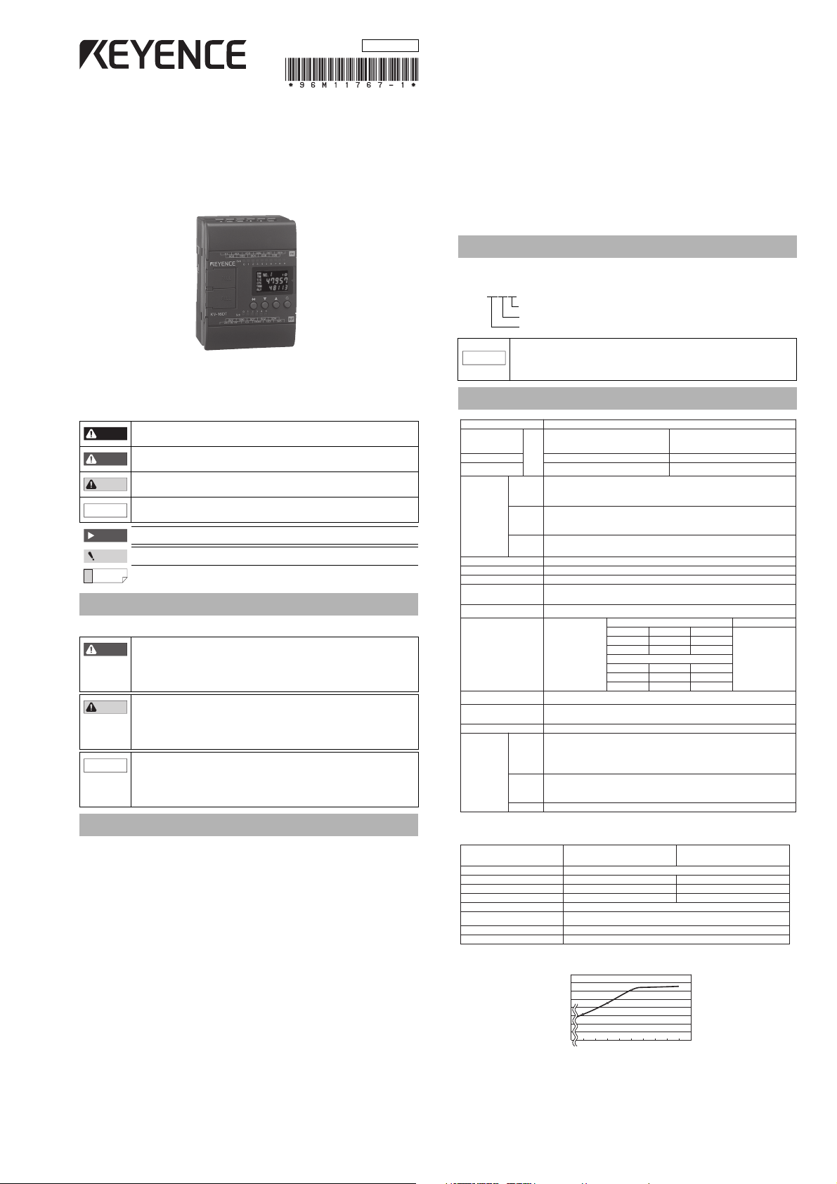
96M11767
Super-small Programmable Logic Controller
with Built-in Display
KV Series Basic Unit
Instruction Manual
Read this manual before using the product in order to achieve maximum performance.
Keep this manual in a safe place after reading it so that it can be used at any time.
Symbols
The following symbols alert you to important messages. Be sure to read these messages
carefully.
It indicates a hazardous situation which, if not avoided, will result in
death or serious injury.
It indicates a hazardous situation which, if not avoided, could result in
death or serious injury.
It indicates a hazardous situation which, if not avoided, could result in
minor or moderate injury.
It indicates a situation which, if not avoided, could result in product
damage as well as property damage.
It indicates cautions and limitations that must be followed during operation.
It indicates additional information on proper operation.
It indicates tips for better understanding or useful information.
Low-Voltage Directive (2006/95/EC)
The Low-voltage Directive is applied to AC power type and/or Relay output type.
• Applicable standard EN61131-2
• Over voltage c ateg ory II
• Use this product under pollution degree 2.
• The AC power type models are designed as Class I equipment. Be sure to connect the
protective earthing terminal located on the power supply terminal to the protective
earthing conductor in the building installation.
• This product has the temperature derating curve depends on the Continuous
Simultaneous ON Ratio. Install the product within the tempeature derating curve.
• Use insulated type crimp-style terminals.
• For wiring materials, use lead wires whose sheath is 0.4 mm or more.
• The KV Series is allowed to be installed in a front installation only. (Spacers for
expansion units are not available.)
• This product is an open type device. Therefore, it must be installed in an enclosure with
IP54 or higher. (e.g. Industrial control panel)
• For wiring to the Power input terminal, Input terminal block and Output Terminal block,
use stranded copper wire having a gage of AWG#16 to #24. The tightening torque is 0.5
N·m.
Model of a Basic Unit
Basic unit model designation
The model of a KV Series basic unit is indicated as follows:
When the ladder support software "KV-IncrediWare (DOS)" or
"LADDER BUILDER for KV Ver. 1.0x" is used, the change all function
NOTICE
on the monitor is not available. Using the change all function may
damage the basic unit. Never use the change all function.
Specifications
Safety Information for KV Series
General Precautions
• Do not use this product for the purpose to protect a human body or
a part of human body.
• This product is not intended for use as explosion-proof product. Do
not use this product in a hazardous location and/or potentially
explosive atmosphere.
• At startup and during operation of the Ladder Builder for KV, be
sure to monitor the functions and performance of the KV Series
basic unit and the KV CPU.
• We recommend that you take substantial safety measures to avoid
any damage in the event a problem occurs.
• Do not open or modify the KV or use it in any way other than
described in the specifications.
• When the KV is used in combination with other instruments,
Precautions on Regulations and Standards
CE Marking
Keyence Corporation has confirmed that this product complies with the essential requirements of
the applicable EC Directive, based on the following specifications. Be sure to consider the
following specifications when using this product in the Member State of European Union.
EMC Directive(2004/108/EC)
• Applicable standard EMI : EN61131-2, Class A
• Any of the following specifications must be considered if the DC power type (the letter
"D" is assigned in models) is installed for use.
- The length of cable connected to the power supply connector must be less than
or equal to 30 m.
-
Mount the following silicon surge protector to the power input terminal of the unit.
Okaya Electric Industries Co., Ltd.: RSP-DC24Q-4 (However, shorten the cable
length of the silicon surge protector to 100 mm or less)
• When you use the relay output type unit (A model type with R on the end), connect the
pressure resistance spark killer which has an appropriate load capacity to the output
terminal in tandem with the contact. (As the equipment discharges when the relay
contact opens and a noise occurs)KEYENCE use the following spark killer for the test.
Okaya Electric Industries Co., Ltd.: XEB0101 0.1μF-10
• As for KV-24AR/T(P) and KV-40AR/T(P), insert the following ferrite core once to the AC
power input terminal, and for KV-40DR/T(P) to the DC power input terminal.
TDK Corporation: ZCAT3035-1330
Remarks:
These specifications do not give any guarantee that the end-product with this product
incorporated complies with the essential requirements of EMC Directive. The manufacturer
of the end-product is solely responsible for the compli ance on the end-product itself
according to EMC Directive.
functions and performance may be degraded, depending on
operating conditions and the surrounding environment.
EMS : EN61131-2
Common I/O specifications
Input specifications
*
For 5 V ±10%, refer to the 5 V mode response frequency characteristic chart (representative example).
1
40
35
30
25
20
15
10
5
0
5.55.45.35.25.154.94.84.74.6
KV Series Basic Unit-IM_E
Page 2
Output specifications
Point
Instantaneous power interruption: Less than 40 ms
Instantaneous power interruption: 40 ms or more
Rated voltage
Rated voltage
Rated voltage
Rated voltage
Point
NOTICE
Front installation
Correct Incorrect
* See page 3.
Installation on ceiling
Upward installation Vertical installation
Correct
Incorrect
20 mm
20 mm
10 mm
Point
(relay output): KV-10AR/DR, KV-16AR/DR, KV-24AR/DR, and KV-40AR/DR
(transistor output): KV-10AT(P)/DT(P), KV-16AT(P)/DT(P), KV-24AT(P)/DT(P),
Item Specifications (relay output): Specifications (transistor output):
Rated load
Peak load current
ON resistance
Rising operating
time (OFF → ON)
Falling operating
time (ON → OFF)
Common method
Relay service life
Relay
replacement
and KV-40AT(P)/DT(P)
250 V AC/30 V DC, 2 A (inductive load),
4 A (resistive load)
5A 0.2 A (500 to 502), 1 A (others)
50 mΩ or less
10 ms or less
10 ms or less
Each common terminal is
independent.
Electrical service life: 100,000 times
or more (20 times/min)
Mechanical service life: 20,000,000
times or more
Not allowed
30 V DC, 0.1 A (500 to 502), 0.3 A (others)
Maximum
voltage at OFF
Leak current in
OFF status
Residual voltage
in ON status
10 µs or less (500 to 502) (at 5 to 100 mA),
20 µs or less (others) (at 10 to 300 mA)
10 µs or less (500 to 502) (at 5 to 100 mA),
100 µs or less (others) (at 10 to 300 mA)
1 common
Output
frequency
Built-in serial
resistance
1.6 kΩ 1/2 W (R500 to R502)
30VDC
100 µA or less
0.8Vorless
50 kHz (500 to 502)
AC Power Specifications
metInsoitacificepS
dohteM dohtemgnihctiwS
esionelppiR sselrop-pVm042
egatlovtuptuO CDV42
yticapactuptuO A7.0:xA04-VKA6.0:xA42-VKA6.0:xA61-VKA4.0:xA01-VK
esufdesU epytgnitlem-tsaF:scitsiretcarahC,A51.3:tnerrucdetar,CAV042:egatlovdetaR
* Includes the internal current consumption and current consumption of expansion units.
KV Series operation at power interruption
Drop in supply voltage
• When the supply voltage drops, the KV Series stops operating and the output turns off.
Detection of instantaneous power interruption
• An AC type basic unit continues operating against instantaneous power interruption of
less than 40 ms. A DC type basic unit continues operating against instantaneous power
interruption of less than 2 ms.
• An AC type basic unit may or may not accept instantaneous power interruption of 40 ms
or more. A DC type basic unit may or may not accept instantaneous power interruption
of 2 ms or more.
• When accepting instantaneous power interruption, a basic unit stops operating and the
output turns off.
Automatic recovery
• Once the supply voltage recovers, the KV Series restarts operation automatically.
noitpmusnoctnerrucrewopCA A7.0:xA04-VKA4.0:xA42-VKA5.0:xA61-VKA4.0:xA01-VK
egatlovtupnirewopCA (CAV042ot001
rotcafrewopCA %06
noitpmusnocrewoP W42:xA04-VKW12:xA42-VKW12:xA61-VKW41:xA01-VK
The maximum output capacity available with the AC type service
power output is the output capacity of each basic unit subtracted by
the internal current consumption of the basic unit, connected
expansion units, and connected peripheral units.
If the supply voltage increases gradually or drops, the KV Series may repeat
operation and then stop. If problems continue to occur with equipment and
other operations from repetitive starts and stops, provide a protection circuit
so that the output shuts down until the voltage reaches the rated value.
)%01
±
%01
±
Installation Environment
Installation environment
• Locations exposed to direct sunlight
• Locations whose ambient temperature is outside the allowable range of 0 to +50°C (32
to 122°F) (No freezing)
• Locations whose ambient humidity is outside the allowable range of 35 to 85% RH (No
condensation)
• Locations subject to drastic temperature change where condensation may occur
• Locations with corrosive or flammable gases
• Locations with excessive dust, salt, iron powder, or soot
• Locations subject to direct vibrations and impacts
• Locations subject to splashes of water, oil, chemicals, etc.
• Locations where a strong magnetic or electrical field is generated
Units are made of synthetic resin. If the unit surf ace touches a solvent with a strong
dissolving force, it could melt. Keep such solvents away from the units.
.
Installation Position
Installation direction
When attaching a unit inside a panel, install the unit so that the front face (equipped with the
access window, communication ports, etc.) faces front or upward.
Distance between adjacent panels/equipment
When installing a unit, keep the distances shown on the right
between the panel or equipment so that the power suppl y can
release heat.
• If the temperature inside the panel exceeds 50°C (122°F), which is
specified as the maximum ambient operating temperature, then
install heat exchangers, etc. to reduce the temperature.
• Ensure sufficient ventilation space so that the power supply can
release heat.
• Never install a unit just above any equipment which generates a lot
of heat.
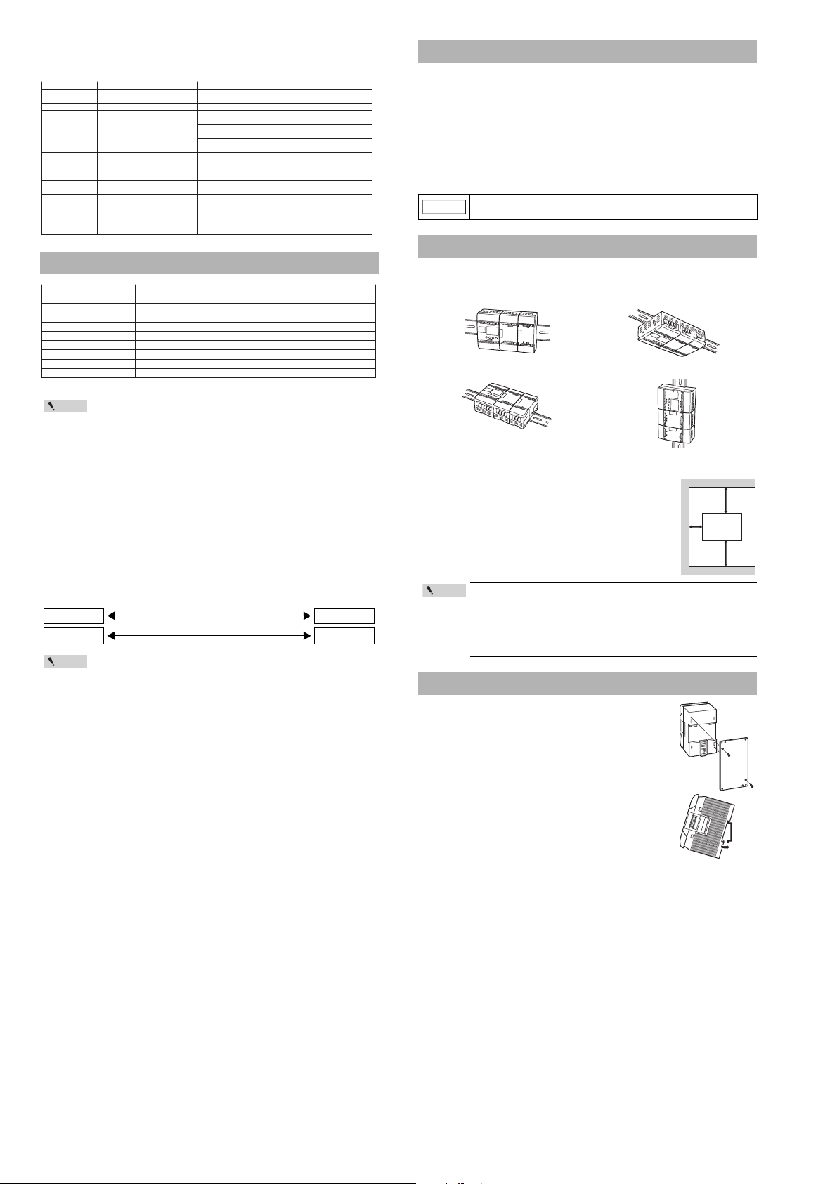
Installation Procedure
This section describes how to attach a connected unit directly to a
panel, to a DIN rail, or to a DIN rail with an expansion unit spacer.
Attaching a unit directly to a panel
Attach a metal fixture for screw tightening to a KV Series basic unit
with set screws. Then, attach the basic unit with a metal fixture
directly to the panel.
Attaching a unit to a DIN rail
Hang an upper claw of a KV Series basic unit to the upper side of
the DIN rail, and press the basic unit onto the DIN rain until a click
sound is heard.
Removing a unit from a DIN rail
Pull a lower claw of a KV Series basic unit downward from the
front direction using a screwdriver, and then remove the basic unit
from the DIN rail.
KV Series Basic Unit-IM_E
2
Page 3

Cautions on Wiring for Each Unit
NOTICE
24 V DC service
power supply
(supplied from
outside)
Grounding
The power input
terminals at the lower
side of the unit
Insulating transformer,
noise filter, etc.
Breaker
AC100 to
240 V
±10%
KV-10AR
Point
24 V DC external power supply
Breaker
Point
RL
24 V DC
KV
Sensor
Ground
Shielded cable
Input
Output
M3
6.0 maximum
Completely grounding
012345
0123456789
5ch
0ch
C1 001 003 005 007 009
008006004002
500
KV-16AR
C324V-OUT-OV C4 503 505
501 502 504
000
IN
OUT
EYENCE
24V
5V
INPUT
VOLT
AC100V-240V
0.5A 50/60Hz
L
~
N
.oNemaNnoitcnuF
1etalplanimrettupnI .)tupniV5otdegnahcebnac700ot000(etalplanimrettupniCDV42
2etalplanimrettuptuO
Output terminal plate. Pulse output function is built in 500 to 502 (in transistor output type only).
k6.1A Ω .)revirdrotomatcennocot(205Rnitliubsirotsisergnitimiltnerruc
3
lanimrettupnirewoP
))P(TD/RD-VK(
.CDV42seilppuS
lanimrettuptuorewoP
))P(TA/RA-VK(
tinuehtfoedisrewolehtnoslanimrettupnirewopehtotCAV042ot001seilppuS
.lanimretCDV42ehtmorfnekatebotrewopecivresswolladna
4spmalrotacidnitupnI .NOtapusthgilpmalhcaE.sutatstupnietacidnI
5spmalrotacidnituptuO .NOtapusthgilpmalhcaE.sutatstuptuoetacidnI
6)edisnodedivorp(rotcennoC .tinunoisnapxenatcennocotdesU
7wodniwsseccA
sasretnuocdnasremitfoseulavtesdnatnerrucehtegnahcdnaotreferotdesU
.seiromematadfostnetnocehtsallew
.sutatsnoitarepoehtsetacidnirolocthgilkcabehT
sutatsrorrE:dergnihsalFedomMARGORP:dernitiLedomNUR:neergnitiL
8syekgnitteS .wodniwsseccaehtotgnirreferelihw.cte,seulavtnerrucegnahcdnaotreferotdesU
9hctiwsrotcelesegatlovtupnI
.tinucisabehtfoegatlovtupniehtsegnahC
tupniV5:tupniV42:
01AtropnoitacinummoC
Modular connector for connecting a personal computer, handheld programmer, or operator panel.
11BtropnoitacinummoC
Modular connector for connecting a personal computer, handheld programmer, or operator panel.
6.
Connector (provided on side)
2. Output terminal block
3. Power input terminal
10.Communication
port A
9. Input voltage selector
switch
Provided on side
1. Input terminal block
4. Input indicator lamps
5. Output indicator lamps
7. Access window
11. Communication
port B
(Power input terminals for
AC power types are provided
on the lower
side of the
unit.)
8. Setting keys
503
502C4501
C35000V24V
• C3 and C4 are each independent.
Internal circuit
Internal circuit
C4
501
C3 503 505
500 502 504
0V
24V
C1 001 003 005 007 009
000 002 004 006 008
24V 0V C3 C4 503 505
500 501 502 504
• C3 and C4 are each independent.
Internal circuit
Internal circuit
C1 001 003 005 007 009 011 013 015
000 002 004 006 008 010 012 014
24V 0V C3 C4 C5 C6 505 507
500 501 502 503 504 506
C6
503
C5 505 507
502 504 506
C4C3
501500
0V
24V
500
501
502 to 503
504 to 507
C3
C4
C5
C6
• C3 to C6 are each independent.
Internal circuit
Internal circuit
This section describes cautions to keep in mind when wiring is performed for I/O units. Be
sure to read this section before starting wiring.
Wiring procedures for basic units
The wiring procedures for basic units are described below.
• Turn off the power before starting wiring.
• For the installation position, select a location whose ambient
temperature is 0 to +50°C (32 to 122°F) (No freezing), whose
ambient humidity is 35 to 85% RH (No condensation), and one
which is not subject to drastic temperature changes.
• If the 24 V DC + output terminal and the 24 V DC - output terminal
are switched, the power supply unit and connected units may be
damaged. Never switch them.
• Be sure that the sum of the current consumption of all connected
units does not exceed the output capacity of the service power
supply. If the system is operating in an overload status, the internal
circuits may generate heat or be damaged. To recover from an
overload status, disconnect some of the connected units.
• Never connect the DC output of any other power supply, either in
serial or parallel, to the 24 V DC output terminals. If the DC output is
connected, the power supply unit may be damaged.
Wiring for an AC type basic unit
For an AC type basic unit, perform the wiring as shown in the figure below.
• Connect an insulating transformer (1:1) or noise filter to reduce line noise.
• Use twisted cables to reduce induction effects.
• When using a basic unit in a location with a lot of noise, the noise
may be reduced by using completely grounding the basic unit.
Wiring for a DC type basic unit
For a DC type basic unit, perform the wiring as shown in the figure below.
.
001 002 003 004 005
000
EYENCE
KV-10AR
C1
000
EYENCE
C2
0ch
012345
0123
5ch
50024V-OUT-OV C3 C4 503
KV-10DR
001 002 003 004 005
C2
C1
0ch
012345
IN
501 502
OUT
IN
Contact Protection
If inductive loads such as clutches, motors, and solenoids are used, a rush current may flow
when the load power supply is turned on, or a counter electromotive voltage may be
generated when the load power supply is shut down. The rush current and the counter
electromotive voltage can contribute considerably to shortening the service life of the
contacts. To prevent this from happening, provide a contact protection circuit.
Part Names and Functions
• Connect the power supply to the power supply input terminals with
24 VDC output, which offers a sufficient margin of power capacity.
Usually, the sum of the current consumption of all connected units
multiplied by 1.5 or more is required for the power capacity.
• To reduce line noise, insert a ferrite core.
Cautions on wiring for I/O units
When performing wiring for an I/O unit, pay strict attention to the following contents.
• Separate input lines from output lines in wiring.
• If the wiring for power is located near I/O signal lines, a malfunction may occur caused
by the effects of a high voltage and large current.
• Keep I/O signal lines away from the power wiring by at least 100 mm.
• Separate 24VDC I/O lines from 100 VAC and 200 VAC lines.
• When using pipes for wiring, make sure that the pipes are securely grounded.
When I/O signal lines cannot be separated from the wiring for power
In such a case, perform grounding on the KV side using batch-shielded cables. (In some
environments, grounding should be performed on the reverse side of the KV.)
Term inal
The terminal screws used are M3. When performing wiring with crimp-style terminals, use
the following ones.
Cautions on grounding
Because the KV Series is constructed to be sufficiently resistant to noise, it can usually be
used without being grounded. However, when the KV Series is used in an environment with
a lot of noise, grounding is required. In such a case, pay strict attention to the following
contents.
• Perform completely grounding for each individual unit. In this case, the ground
resistance should be 100 ¾ or less.
• If individual grounding is not possible, perform common grounding. In this case, the
length of each grounding cable should be equal.
KV KV
A
A = B A > B
0123
KV-10DR
5ch
50024V-IN-OV C3 C4 503
B
KV
A
501 502
A < B
OUT
Terminal layout drawings and I/O circuit diagrams
KV-10AR/DR (Relay output type)
Terminal layout drawing Output circuit diagram
000 001 002 003 004 005
C1 C2
500
501 to 503
501 502
24V 0V 500 C3 C4 503
C3
C4
KV-16AR/DR (Relay output type)
Terminal layout drawing Output circuit diagram
500 to 501
502 to 505
C3
C4
KV-24AR/DR (Relay output type)
Terminal layout drawing Output circuit diagram
B
3
KV Series Basic Unit-IM_E
Page 4

Terminal layout drawings and I/O circuit diagrams
C1 001 003 005 007 009 011 013 015 101 103 105 107
24V 0V C3 C4 C5 C6 505 507 509 511 C8 513 515
000 002 004 006 008 010 012 014 100 102 104 106
500 501 502 503 504 506 508 510 C7 512 514
C6
503
C5 505 507 509 511 C8 513 515
502 504 506 508 510 C7 512 514
C4C3
501500
0V
24V
• C3 to C8 are each
independent.
Internal circuit
Internal circuit
005
004 002 000
C1001003
*
C1 is shared
in common.
Three wire
tipe
Brown
Black
Blue
Three-wire
tipe
Brown
Blue
Three-wire
tipe
Brown
Black
Blue
Three-wire
tipe
Brown
Black
Blue
Three-wire
tipe
Brown
Black
Blue
Three-wire
tipe
Brown
Black
Blue
Three-wire
tipe
Brown
Black
Blue
Circuit
000 to 007
C1
4.3 KΩ
Circuit configuration of inputs 000 to 007
Circuit configuration of inputs 008 to 107
Internal circuit
Internal circuit
Photocoupler
insulation
Photocoupler
insulation
24 V/5 V
selector
circuit
000 001 002 003 004 005
24V 0V 500 C3 C4 503
C1 C2
501 502
503
500
502
R502
501
C3
*
0V24V
Insultating
power
supply
Internal circuit
500 to 503
C3
R502
1.6 kΩ W
1
2
•A 1.6 k current limiting resistor is built in R502
(to connect a motor driver).
Internal circuit
NPN
* For KV-10ATP/KV-10DTP
PNP
Insultating
power
supply
Internal circuit
500 to 505
C3
R502
1.6 kΩ W
1
2
C1 001 003 005 007 009
000 002 004 006 008
24V 0V C3
R502
503 505
24V 500 501 502 504
500 to 505
C3
R502
1.6 kΩ
W
1
2
Insultating
power
supply
Internal
circuit
•A 1.6 k current limiting resistor is built in
R502 (to connect a motor driver).
Internal circuit
NPN
* For KV-16ATP/
KV-16DTP
PNP
Insultating
power
supply
Internal circuit
R500 to R502
C3
500 to 507
1.6 kΩ W
1
2
•A 1.6 k current limiting resistor is built in each
of R500 to R502 (to connect a motor driver).
• V1 to V3 are short-circuited inside (so they
can be used as a relay terminal block).
Internal circuit
NPN
* For KV-24ATP/KV-24DTP
PNP
C1 001 003 005 007 009 011 013 015 101 103 105 107
24V 0V C3
R500 R501 R502
V3 505 507 509 511 513 515
000 002 004 006 008 010 012 014 100 102 104 106
V1 V2 500 501 502 503 504 506 508 510 512 514
V2
R5O1
501
R502
502V3503
505
504
507
506
R500
500
V1
C30V*24V 509
508
511
510
513
512
515
514
500 to 515
C3
R500 to R502
1.6 kΩ W
1
2
Insultating
power
supply
Internal
circuit
•A 1.6 k current limiting resistor is built in each of R500 to R502 (to connect a motor driver).
• V1 to V3 are short-circuited inside (so they can be used as a relay terminal block).
Internal circuit
NPN
* For KV-40ATP/KV-40DTP
PNP
000 to 007
C1
4.3 kΩ
008 to 107
C1
4.3 KΩ
510 Ω
005
004 002 000
C1001003
*
C1 is shared
in common.
Three wire
tipe
Brown
Black
Blue
Three-wire
tipe
Brown
Blue
Three-wire
tipe
Brown
Black
Blue
Three-wire
tipe
Brown
Black
Blue
Three-wire
tipe
Brown
Black
Blue
Three-wire
tipe
Brown
Black
Blue
Three-wire
tipe
Brown
Black
Blue
Circuit
Circuit configuration of inputs 000 to 007
Circuit configuration of inputs 008 to 107
Internal circuit
Internal circuit
Photocoupler
insulation
Photocoupler
insulation
24 V/5 V
selector
circuit
KV-40AR/DR (Relay output type)
Terminal layout drawing
KV-24AT(P)/DT(P) (Transistor output type)
Terminal layout drawing Output circuit diagram
C1 001 003 005 007 009 011 013 015
000 002 004 006 008 010 012 014
V1
V2
501
502V3503
500
R500
C30V24V
*
504
R5O1
R502
506
505
507
Output circuit diagram
Input circuit diagram (KV-AR/KV-DR)
*The number of input points varies with the model.
008 to 107
C1
4.3 KΩ
510 Ω
500
501
502 to 503
504 to 507
508 to 511
512 to 515
C3
C4
C5
C6
C7
C8
V1 V2 500 501 502 503 504 506
24V 0V C3
R500 R501 R502
V3 505 507
Internal
circuit
Insultating
power
supply
KV-40AT(P)/DT(P) (Transistor output type)
Terminal layout drawing
Output circuit diagram
1
1.6 k
2
Ω W
R500 to R502
500 to 507
C3
C3
KV-10AT(P)/DT(P) (Transmitter output type)
Terminal layout drawing Output circuit diagram
1.6 kΩ W
1
2
R502
500 to 503
C3
Internal
circuit
Insultating
power
supply
KV-16AT(P)/DT(P) (Transistor output type)
Terminal layout drawing Output circuit diagram
KV Series Basic Unit-IM_E
24V
500 502
501
C3
*
503
R502
504
5050V24V
Input circuit diagram (KV-AT( P) /K V-DT(P))
*The number of input points varies with the model.
4
Internal circuit
Insultating
power
supply
1.6 kΩ W
1
2
500 to 515
R500 to R502
Page 5

Relationship between Continuous Simultaneous
NOTICE
110
100
90
80
70
60
50
40
30
20
10
0
30 35 40 45 50
Individual unit
With expansion unit
Continuous simultaneous ON ratio (%)
Ambient temperature (°C)
110
100
90
80
70
60
50
40
30
20
10
0
30 35 40 45 50
45°C
58%
Individual unit
With expansion unit
Continuous simultaneous ON ratio (%)
Ambient temperature (°C)
110
100
90
80
70
60
50
40
30
20
10
0
30 35 40 45 50
48°C
80%
Individual unit
With expansion unit
Continuous simultaneous ON ratio (%)
Ambient temperature (°C)
110
100
90
80
70
60
50
40
30
20
10
0
30 35 40 45 50
Individual unit
With expansion unit
Continuous simultaneous ON ratio (%)
Ambient temperature (°C)
110
100
90
80
70
60
50
40
30
20
10
0
30 35 40 45 50
36°C 37°C
41°C
40°C
39°C
50%
38%
18%
13%
44%
49
L=0
L=1/2Max.
L=1/2Max.
L=Max.
L=Max.
L=0
35°C
Individual unit
With expansion unit
Continuous simultaneous ON ratio (%)
Ambient temperature (°C)
110
100
90
80
70
60
50
40
30
20
10
0
30 35 40 45 50
43°C 47°C
50%
75%
Individual unit
With expansion unit
Continuous simultaneous ON ratio (%)
Ambient temperature (°C)
110
100
90
80
70
60
50
40
30
20
10
0
30 35 40 45 50
44°C 49°C
58%
93%
Individual unit
With expansion unit
Continuous simultaneous ON ratio (%)
Ambient temperature (°C)
110
100
90
80
70
60
50
40
30
20
10
0
30 35 40 45 50
32°C 33°C
29°C
11%
6%
L=0
L=1/2Max.
L=1/2Max.
L=Max.
L=Max.
L=0
31°C
34°C
Individual unit
With expansion unit
Continuous simultaneous ON ratio (%)
Ambient temperature (°C)
110
100
90
80
70
60
50
40
30
20
10
0
30 35 40 45 50
37°C
36°C
29°C 31°C
19%
38%
45%
6%
L=0
L=1/2Max.
L=1/2Max.
L=Max.
L=Max.
L=0
35°C
38°C
Individual unit
With expansion unit
Continuous simultaneous ON ratio (%)
Ambient temperature (°C)
110
100
90
80
70
60
50
40
30
20
10
0
30 35 40 45 50
43°C 44°C
63%
72%
88%
50%
L=0, 1/2Max.
L=Max.
L=0, 1/2Max.
L=Max.
48°C
40°C
Individual unit
With expansion unit
Continuous simultaneous ON ratio (%)
Ambient temperature (°C)
110
100
90
80
70
60
50
40
30
20
10
0
30 35 40 45 50
37°C 43°C
67%
44%
Individual unit
With expansion unit
Continuous simultaneous ON ratio (%)
Ambient temperature (°C)
110
100
90
80
70
60
50
40
30
20
10
0
30 35 40 45 50
47°C
91%
79%
Individual unit
With expansion unit
Continuous simultaneous ON ratio (%)
Ambient temperature (°C)
110
100
90
80
70
60
50
40
30
20
10
0
30 35 40 45 50
43°C
41%
50%
90%
83%
75%
L=1/2Max.
L=Max.
L=0
L=1/2Max.
L=Max.
L=0
48°C46°C
41°C
44°C
45°C
Individual unit
With expansion unit
Continuous simultaneous ON ratio (%)
Ambient temperature (°C)
ON Ratio and Ambient Temperature
If the number of I/O points which turn ON at the same time exceeds the
specifications range, the unit may be damaged.
The graphs below show the relationship between the ambient temperature and the
continuous simultaneous ON ratio.
Load current L:
(AC power output
capacity at 400 mA)
KV-10AR/AT (P)/DR/DT (P)
Derating when KV-10AR is mounted upward Derating when KV-10AR is mounted in front
110
100
90
80
70
60
50
40
30
20
10
0
Continuous simultaneous ON ratio (%)
Derating when KV-10AT(P) is mounted upward Derating when KV-10AT(P) is mounted in front
110
100
90
80
70
60
50
40
30
20
10
0
Continuous simultaneous ON ratio (%)
Derating when KV-10DR is mounted upward Derating when KV-10DR is mounted in front
(Individual current
-
consumption when KV-D20
is connected)
41°C
44°C
42°C
39°C
L=0
L=1/2Max.
L=Max.
L=0
L=1/2Max.
41°C 43°C 46°C 47°C
L=0
L=1/2Max.
L=Max.
L=Max.
L=0
Individual unit
With expansion unit
30 35 40 45 50
Ambient temperature (°C)
Individual unit
With expansion unit
30 35 40 45 50
Ambient temperature (°C)
(Service power
=
output current)
110
46°C
49
100
90
80
70
63%
60
50
40
38%
30
25%
20
10
0
Continuous simultaneous ON ratio (%)
86%
68%
60%
30%
(Expansion unit current
+
consumption)
47°C 48°C
45°C
L=Max.
L=0,1/2Max.
L=Max.
Individual unit
With expansion unit
30 35 40 45 50
Ambient temperature (°C)
86%
79%
64%
Derating when KV-16DT(P)is mounted upward Derating when KV-16DT(P) is mounted in front
110
100
90
80
70
60
50
40
30
20
Individual unit
10
With expansion unit
0
Continuous simultaneous ON ratio (%)
30 35 40 45 50
Ambient temperature (°C)
KV-24AR/AT (P)/DR/DT (P)
Load current L:
(AC power output
capacity at 600 mA)
43°C 47°C
(Individual current
-
consumption when KV-D20
is connected)
75%
50%
110
100
90
80
70
60
50
40
30
20
10
0
Continuous simultaneous ON ratio (%)
(Service power
=
output current)
44°C 49°C
Individual unit
With expansion unit
30 35 40 45 50
Ambient temperature (°C)
(Expansion unit current
+
consumption)
93%
58%
Derating when KV-24AR is mounted upward Derating when KV-24AR is mounted in front
110
100
90
80
70
60
50
40
30
20
10
0
Continuous simultaneous ON ratio (%)
Derating when KV-24AT(P) is mounted upward Derating when KV-24AT(P) is mounted in front
37°C 40°C
L=0 to Max.
L=0 to Max.
Individual unit
With expansion unit
30 35 40 45 50
Ambient temperature (°C)
56%
44%
Derating when KV-10DT(P) is mounted upward Derating when KV-10DT(P) is mounted in front
110
100
90
80
70
60
50
40
30
20
Individual unit
10
With expansion unit
0
Continuous simultaneous ON ratio (%)
30 35 40 45 50
Ambient temperature (°C)
KV-16AR/AT (P)/DR/DT (P)
Load current L:
(AC power output
capacity at 600 mA)
Derating when KV-16AR is mounted upward Derating when KV-16AR is mounted in front
110
100
90
80
70
60
50
40
30
20
10
0
Continuous simultaneous ON ratio (%)
Derating when KV-16AT(P) is mounted upward Derating when KV-16AT(P) is mounted in front
(Individual current
-
consumption when KV-D20
is connected)
36°C 37°C
35°C
39°C
L=1/2Max.
L=Max.
L=0
L=1/2Max.
Individual unit
With expansion unit
30 35 40 45 50
L=Max.
Ambient temperature (°C)
40°C
49°C
88%
(Service power
=
output current)
110
41°C
L=0
49
100
90
80
70
60
50
50%
44%
40
38%
30
20
18%
13%
10
0
Continuous simultaneous ON ratio (%)
110
100
90
80
70
60
50
40
30
20
10
0
Continuous simultaneous ON ratio (%)
(Expansion unit current
+
consumption)
47°C
44°C
46°C
L=0, 1/2Max.
L=0, 1/2Max.
L=Max.
L=Max.
Individual unit
With expansion unit
30 35 40 45 50
Ambient temperature (°C)
47°C
44°C
46°C
L=0, 1/2Max.
L=0, 1/2Max.
L=Max.
L=Max.
Individual unit
With expansion unit
30 35 40 45 50
Ambient temperature (°C)
49°C
91%
75%
66%
50%
49°C
91%
75%
66%
50%
Derating when KV-16DR is mounted upward Derating when KV-16DR is mounted in front
Derating when KV-24DR is mounted upward Derating when KV-24DR is mounted in front
110
30°C 35°C
100
90
80
70
60
50
40
30
20
Individual unit
10
With expansion unit
0
Continuous simultaneous ON ratio (%)
30 35 40 45 50
Derating when KV-24DT(P)is mounted upward Derating when KV-24DT(P) is mounted in front
KV-40AR/AT (P)/DR/DT (P)
Load current L:
(AC power output
capacity at 700 mA)
Ambient temperature (°C)
110
100
90
80
70
60
50
40
30
20
Individual unit
10
With expansion unit
0
Continuous simultaneous ON ratio (%)
30 35 40 45 50
Ambient temperature (°C)
37°C 42°C
(Individual current
-
consumption when KV-D20
is connected)
42%
16%
67%
39%
(Service power
=
output current)
(Expansion unit current
+
consumption)
Derating when KV-40AR is mounted upward Derating when KV-40AR is mounted in front
110
33°C
100
90
80
70
60
50
40
30
20
10
0
Continuous simultaneous ON ratio (%)
Derating when KV-40AT(P) is mounted upward Derating when KV-40AT(P) is mounted in front
110
100
90
80
70
60
50
40
30
20
10
0
Continuous simultaneous ON ratio (%)
34°C
35°C
32°C
Individual unit
With expansion unit
30 35 40 45
Ambient temperature (°C)
27°C
33°C 34°C
31°C
Individual unit
With expansion unit
30 35 40 45 50
Ambient temperature (°C)
L=0
L=1/2Max.
L=0
L=1/2Max.
L=1/2Max. Max
L=Max.
35°C
L=Max.
L=0
L=1/2Max.
L=Max.
L=0
49
48
49
110
100
90
80
70
60
50
40
33%
30
27%
20
Individual unit
10
Continuous simultaneous ON ratio (%)
0
With expansion unit
6%
38%
27%
39°C
44°C 45°C
40°C
41°C
37°C
L=1/2Max.
L=Max.
L=1/2Max.
30 35 40 45 50
Ambient temperature (°C)
L=0
L=0
L=Max.
75%
70%
55%
16%
8%
5
KV Series Basic Unit-IM_E
Page 6

Derating when KV-40DR is mounted upward Derating when KV-40DR is mounted in front
110
100
90
80
70
60
50
40
30
20
10
0
30 35 40 45 50
33°C 36°C
53%
34%
Individual unit
With expansion unit
Continuous simultaneous ON ratio (%)
Ambient temperature (°C)
110
100
90
80
70
60
50
40
30
20
10
0
30 35 40 45 50
42°C 46°C
80%
60%
Individual unit
With expansion unit
Continuous simultaneous ON ratio (%)
Ambient temperature (°C)
110
100
90
80
70
60
50
40
30
20
10
0
30 35 40 45 50
40°C36°C
54%
30%
Individual unit
With expansion unit
Continuous simultaneous ON ratio (%)
Ambient temperature (°C)
110
100
90
80
70
60
50
40
30
20
10
0
30 35 40 45 50
48°C44°C
87%
62.5%
Individual unit
With expansion unit
Continuous simultaneous ON ratio (%)
Ambient temperature (°C)
111
99
50
(66)
64
(79)
6-ø5.0
(Mounting hole)
Main unit
mounting hole*
(2 positions)
t=2
31
(48)
* Two M3.5 countersunk-head screws are
included for mounting the main unit.
KV-40AR/AT(P)/DR/DT(P)
(40-I/O basic unit)
OP-35348
Copyright (c) 2011 KEYENCE CORPORATION. All rights reserved.
11767E 1081-1 96M11767 Printed in Japan
Derating when KV-40DT(P)is mounted upward Derating when KV-40DT(P) is mounted in front
Dimensions
24.5
9.9
17
35.4 90
35.4 90
17.5
4.1
3.8
A
22
70
4
22
KV-10AR/AT(P)/DR/DT(P) (10-I/O basic unit)
KV-16AR/AT(P)/DR/DT(P) (16-I/O basic unit)
KV-24AR/AT(P)/DR/DT(P) (24-I/O basic unit)
KV-40AR/AT(P)/DR/DT(P) (40-I/O basic unit)
3.8
4
43
20.5
A
55
65
80
110
Metal Fixture for Screw Tightening
KV-10AR/AT(P)/DR/DT(P) KV-16 (24) AR/AT(P)/DR/DT(P)
(10-I/O basic unit) (16 (24) -I/O basic unit)
OP-35345 OP-35346 (OP-35347)
Main unit
mounting hole*
(2 positions)
* Two M3.5 countersunk-head screws are
included for mounting the main unit.
4-ø5.0
(Mounting hole)
40
54
11199
t=2
WARRANTIES AND DISCLAIMERS
(1) KEYENCE warrants the Products to be free of defects in materials and
workmanship for a period of one (1) year from the date of shipment. If any
models or samples were shown to Buyer, such models or samples were
used merely to illustrate the general type and quality of the Products and
not to represent that the Products would necessarily conform to said
models or samples. Any Products found to be defective must be shipped to
KEYENCE with all shipping costs paid by Buyer or offered to KEYENCE for
inspection and examination. Upon examination by KEYENCE, KEYENCE,
at its sole option, will refund the purchase price of, or repair or replace at no
charge any Products found to be defective. This warranty does not apply to
any defects resulting from any action of Buyer, including but not limited to
improper installation, improper interfacing, improper repair, unauthorized
modification, misapplication and mishandling, such as exposure to
excessive current, heat, coldness, moisture, vibration or outdoors air.
Components which wear are not warranted.
(2) KEYENCE is pleased to offer suggestions on the use of its various
Products. They are only suggestions, and it is Buyer's responsibility to
ascertain the fitness of the Products for Buyer’s intended use. KEYENCE
will not be responsible for any damages that may result from the use of the
Products.
(3) The Products and any samples ("Products/Samples") supplied to Buyer are
not to be used internally in humans, for human transportation, as safety
devices or fail-safe systems, unless their written specifications state
otherwise. Should any Products/Samples be used in such a manner or
misused in any way, KEYENCE assumes no responsibility, and additionally
Buyer will indemnify KEYENCE and hold KEYENCE harmless from any
liability or damage whatsoever arising out of any misuse of the Products/
Samples.
(4) OTHER THAN AS STATED HEREIN, THE PRODUCTS/SAMPLES ARE
PROVIDED WITH NO OTHER WARRANTIES WHATSOEVER. ALL
EXPRESS, IMPLIED, AND STATUTORY WARRANTIES, INCLUDING,
WITHOUT LIMITATION, THE WARRANTIES OF MERCHANTABILITY,
FITNESS FOR A PARTICULAR PURPOSE, AND NON-INFRINGEMENT
OF PROPRIETARY RIGHTS, ARE EXPRESSLY DISCLAIMED.
IN NO EVENT SHALL KEYENCE AND ITS A FFILIATED ENTITIES BE
LIABLE TO ANY PERSON OR ENTITY FOR ANY DIRECT, INDIRECT,
INCIDENTAL, PUNITIVE, SPECIAL OR CONSEQUENTIAL DAMAGES
(INCLUDING, WITHOUT LIMITATION, ANY DAMAGES RESULTING
FROM LOSS OF USE, BUSINESS INTERRUPTION, LOSS OF
INFORMATION, LOSS OR INACCURACY OF DATA, LOSS OF
PROFITS, LOSS OF SAVINGS, THE COST OF PROCUREMENT OF
SUBSTITUTED GOODS, SERVICES OR TECHNOLOGIES, OR FOR
ANY MATTER ARISING OUT OF OR IN CONNECTION WITH THE USE
OR INABILITY TO USE THE PRODUCTS, EVEN IF KEYENCE OR ONE
OF ITS AFFILIATED ENTITIES WAS ADVISED OF A POSSIBLE THIRD
PARTY’S CLAIM FOR DAMAGES OR ANY OTHER CLAIM AGAINST
BUYER. In some jurisdictions, some of the foregoing warranty disclaimers
or damage limitations may not apply.
BUYER'S TRANSFER OBLIGATIONS:
If the Products/Samples purchased by Buyer are to be resold or delivered
to a third party, Buyer must provide such third party with a copy of this
document, all specifications, manuals, catalogs, leaflets and written
information provided to Buyer pertaining to the Products/Samples.
E 1110-2
* Two M3.5 countersunk-head screws are
included for mounting the main unit.
KV Series Basic Unit-IM_E
Main unit
mounting hole*
(2 positions)
78
109
4-ø5.0
(Mounting hole)
11199
t=2
6
 Loading...