

Page 1
User's Manual
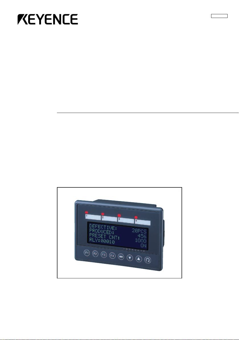
Operator Interface Panel
KV-D20
96M00261
Page 2

Safety Precautions
Symbols
This instruction manual describes the operation and function of the Operator
Interface Panel. Read this manual carefully to ensure safe use and maximum
performance from your KV-D20.
The following symbols alert you to important messages. Be sure to read these
messages carefully.
General Precautions
WARNING
CAUTION
Note:
• At startup and during operation, be sure to monitor the functions and performance of the KV-D20.
• We recommend that you take substantial safety measures to avoid any damage
in the event a problem occurs.
• Do not open or modify the KV-D20 or use it in any way other than described in
the specifications.
• When the KV-D20 is used in combination with other instruments, functions and
performance may be degraded, depending on operating conditions and the
surrounding environment.
• Do not use the KV-D20 for the purpose of protecting the human body.
Failure to follow instructions may lead to injury. (electric
shock, burn, etc.)
Failure to follow instructions may lead to product damage.
Provides additional information on proper operation.
2
Page 3

Note to User
When using the NEW KV Series in the following conditions or environments, be
sure to use the NEW KV Series with sufficient margin regarding the rating and
functions, take appropriate safety precautions such as fail-safe, and contact our
sales personnel if any questions arise.
• Use in conditions or environments not described in this manual
• Use for nuclear power control, railway facilities, air service facilities, vehicles,
combustion devices, medical equipment, amusement machines, safety equipment, etc.
• Use for applications where large effects are predicted to be given on human
lives and properties and safety is especially requested.
Restriction on Acquiring the CE Marking
■ Restriction to be compatible with EMC directives
• When using a relay output type unit (whose model name ends with "R"), connect spark killers having the appropriate withstand voltage against the load to
the output terminals in parallel to contacts (because the unit discharges when a
relay contact becomes open and noise is generated). In our experiments, we
use the following models of spark killers.
XEB0101 0.1 µF-10 Ω manufactured by OKAYA DENKI SANGYO
The following 1-turn ferrite core is added to the AC power input circuit of the KV40AR/T, the KV-24AR/T and to the DC power input circuit of the KV-40DR/T.
ZCAT3035-1330 manufactured by TDK
Note: The contents above do not by themselves ensure that the entire machine
manufactured in accordance with the above contents is compatible with EMC
directives.
You must judge by yourself whether or not the entire machine is compatible with
EMC directives because compatibility may change depending on the component
configuration, wiring and location inside of the machine.
■ Restriction on compatibility with low-voltage directives (IEC-1010-1)
• Use insulated type crimp-style terminals.
• For wiring materials, use lead wires whose sheath is 0.4 mm or more.
• The NEW KV Series is allowed to be installed in a vertical position only.
(Spacers for expansion units are not available.)
• Be sure to use the NEW KV Series inside the control panel.
3
Page 4

Warranty
Caution
Our products are thoroughly inspected before shipment. However, in the event of a
malfunction, contact your nearest KEYENCE office.
KEYENCE will replace or repair any defective parts free of charge for one year
from the date of shipment from the factory. However, we shall not be responsible
for any failure resulting from improper use, negligence, natural disaster or fire.
• No part of this manual may be reprinted or reproduced in any form or by any
means without the prior written permission of KEYENCE CORPORATION.
• The content of this manual is subject to change without notice.
• KEYENCE has thoroughly checked and reviewed this manual. Please contact
the sales office listed at the end of this manual if you have any questions or
comments regarding this manual or if you find an error.
• KEYENCE assumes no liability for damages resulting from the use of the
information in this manual, item 3 above notwithstanding.
• KEYENCE will replace any incomplete or incorrectly collated manual.
All company names and product names in this manual are registered trademarks
or trademarks of their respective owners.
4
Page 5

5
Page 6

Contents
1 Before Operation 8
1.1 Checking Package Contents .................................................................8
1.2 Part Names and Functions ....................................................................9
1.3 Details about the KV-D20 ....................................................................10
General specifications .......................................................................10
Functional specifications....................................................................10
Dimensions ........................................................................................11
1.4 Installation and Environment ..............................................................12
Use environment................................................................................12
Panel mounting..................................................................................13
1.5 Inspection and Maintenance ...............................................................14
Inspection ..........................................................................................14
Maintenance ......................................................................................14
2 Overview and Operation 15
2.1 Use Examples for the KV-D20 .............................................................15
2.2 Connection with the KV Series ...........................................................16
Connection.........................................................................................16
Precautions........................................................................................16
2.3 Overview of the KV-D20 ......................................................................17
Switching the display mode ...............................................................17
Overview of each display mode.........................................................18
Assignment of relays/DM...................................................................19
Other functions ..................................................................................20
Precautions about screen change function........................................23
2.4 Operator Mode .....................................................................................25
Screen selection in operator mode ....................................................25
Operator screen.................................................................................26
Direct access screen .........................................................................34
KV-I/O monitor screen .......................................................................35
Switch comment screen.....................................................................36
Lamp comment screen ......................................................................36
Screen change permission in operator mode ....................................37
2.5 Device Mode .........................................................................................38
Device mode......................................................................................38
Operation example for device mode..................................................40
2.6 System Mode ........................................................................................42
System mode.....................................................................................42
6
Page 7

3 Examples of Ladder Programs 43
3.1 Basic Ladder Programs .......................................................................43
Before creating ladder programs .......................................................43
Basic ladder programs.......................................................................44
3.2 Examples of Ladder Programs ...........................................................51
Example of displaying user messages ..............................................51
Example of displaying messages with titles.......................................53
Example of position control................................................................54
Example of frequency counter ...........................................................57
Example of 24-bit high-speed counter ...............................................60
Example of cam switch function ........................................................62
4 Appendix 66
4.1 Troubleshooting ...................................................................................66
4.2 Available Character List ......................................................................70
4.3 Comment Draft Sheet ..........................................................................71
7
Page 8
1. Before Operation
1. Before Operation
This section includes the names, functions, and details of the KV-D20 and information required before starting operation.
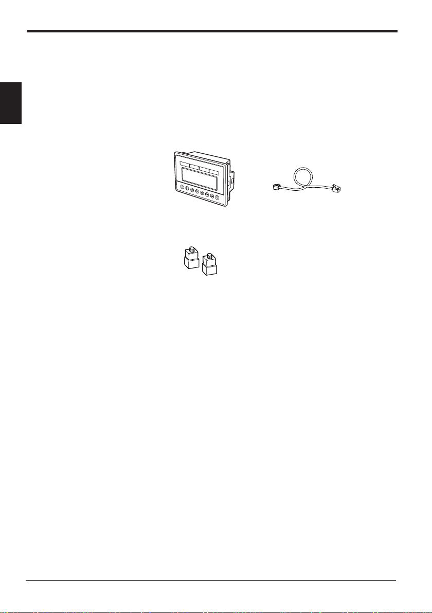
1.1 Checking Package Contents
1
The KV-D20 package includes the following components. Before using the KVD20, check that all components have been included in the package.
76543210
KV-D20 Display
Mounting fixture (2 pcs.)
Modular cable (2.5 m)
OP-26487
8
Page 9
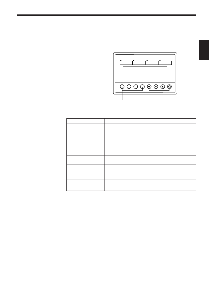
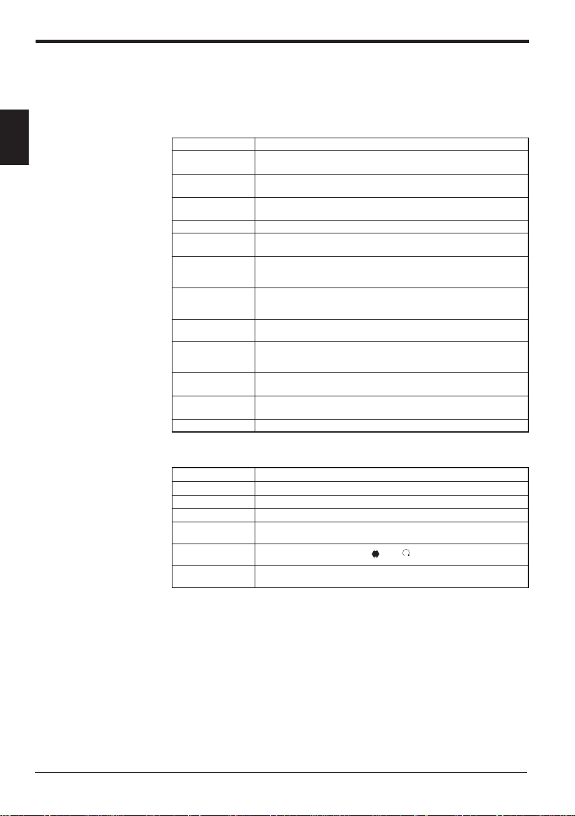
1.2 Part Names and Functions
This section describes the part names and functions of the KV-D20.
1. Before Operation
1. Customized lamps
5. Communication port
(rear side)
6. Bit guide
.oNemaNnoitcnuF
1
2
3
4
5
6
dezimotsuC
spmal
yalpsidDCL
dezimotsuC
sehctiws
noitarepognitteS
sehctiws
trop
noitacinummoC
ediugtiB
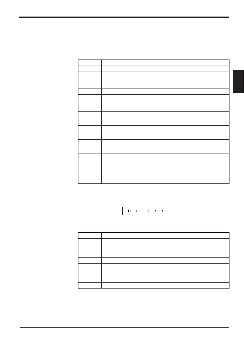
1 2 3 4
F1 F2 F3 F4
2. LCD display
76543210
4. Setting operation switch3. Customized switches
.nosnrutyalergnidnopserroc
.yalpsidneercsegnahC
.)78462-PO(elbacdeilppuseht
.edomecivedehtninoitacidni
1
ehtnehwsetanimulliDELehT.syalerytilitulaicepsotdengissA
)7052:4pmaL,6052:3pmaL,5052:2pmaL,4052:1pmaL(
reddalnidebircsedsretcarahc02otpufostnemmocsyalpsiD
.tinuVKehtnidesusecivedllasyalpsidro,smargorp
.nodenrutsihctiwsgnidnopserroc
)3052:4F,2052:3F,1052:2F,0052:1F(
.tinuVKehthtiwnoitcennocrofdesU
ehtnehwnosnrutyalerehT.syalerytilitulaicepsotdengissA
htiwtinucisabVKehtfotropnoitacinummocehtotdetcennoC
.02D-VKehtotylppusrewopevirdehtseilppusoslA
O/I-VKehtnotibhcaeforebmungnidnopserrocehtswohS
FFO/NOtib-8ehtro,neercsrotarepoeht,neercsrotinom
9
Page 10
1. Before Operation
1.3 Details about the KV-D20
This section describes the general specifications, functional specifications, and
dimensions of the KV-D20.
General specifications
1
metInoitacificepS
ylppusrewoP
egatlov
tnerruC
noitpmusnoc
riagnidnuorruS
erutarepmet
ytidimuhevitaleR
egarotstneibmA
erutarepmet
egatlovdnatshtiW
ytinummiesioN
noitarbiV
noitalusnI
ecnatsiser
latnemnorivnE
snoitcirtser
thgieW
erutcurtS
M05 Ω .nim
.xamAm081,CDV5
05+ot0 °C
%58ot53
07ot02- °C
.nim1rofCAV0051
1:htdiwesluP,.nimp-pV0051 µ sn05dnas
ylevitcepsersruoh2,snoitcerid
)retemmhogemCDV005
sesagevisorrocrotsudevissecxeoN
)CDV5(VKehtfotropnoitacinummocehtmorfdeilppuS
)V42rofdetrevnocnehw.xamAm06(
dna,slanimretO/Idnalanimretrewopneewteb(
)gnisuohdnaslanimretlanretxeneewteb
,)rotalumisesionybdetarenegesioN(
)6-/4-/3-/2-4-00016CEI(dradnatsCEIotgnimrofnoC
ZdnaY,Xniedutilpmaelbuod.xammm5.1,zH55ot01
htiwderusaem,gnisuohdnalanimretrewopneewteB(
,g06.xorppA:elbacnoitacinummoC,g061.xorppA:yalpsiD
).scp2(g03.xorppA:erutxifgnitnuomlaicepS
lenapnoitarepotnorfehtrofylnoF56-PI,lenapni-tliuB
Functional specifications
10
metInoitacificepS
yalpsiD DCLtilkcabepytevitagen-eulB,senil4xstigid02
hctiws
hctiws
stinuelbatcennoC tinucisabVKenorof02D-VKenO
ezisretcarahC )stod7x5(mm57.4xmm59.2
dezimotsuC
noitarepognitteS
pmaldezimotsuC
syalerytilitulaicepsotdengissasehctiws4
)3052:4F,2052:3F,1052:2F,0052:1F(
▼▲
syalerytilitulaicepsotdengissa,sDELdeR4
)7052:4pmaL,6052:3pmaL,5052:2pmaL,4052:1pmaL(
Page 11
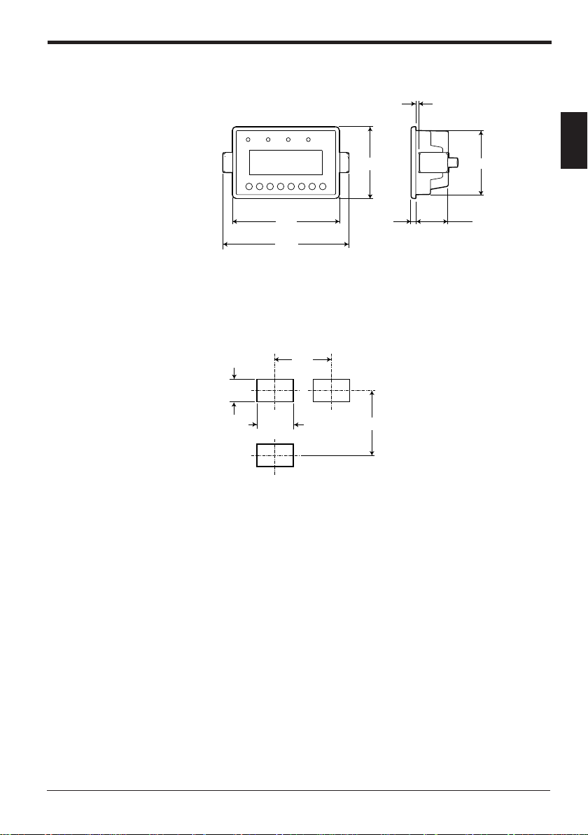
Dimensions
■ KV-D20
1. Before Operation
Panel thickness: 1.2 to 3.0 mm
1
75
67
(Including mounting fixtures)
■ Panel cutout
+1
68
0
112
133
145
+1
105 83
0
5
34
11
Page 12

1. Before Operation
1.4 Installation and Envir onment
This section describes the panel mounting method and precautions for installation.
Use environment
1
This section describes environment, location, and wiring precautions for the KVD20.
■ Locations
Avoid installing the KV-D20 in the following locations:
• Locations in which the KV-D20 may be subjected to direct sunlight.
• Locations in which the surrounding air temperature drops below 0°C or
exceeds 50°C.
• Locations in which the relative humidity drops below 35% or exceeds 85%.
• Locations in which condensation occurs due to sudden temperature drops.
• Locations in which there are corrosive or flammable gases.
• Locations exposed to dust, salt, metal particles, or greasy fumes.
• Locations in which the KV-D20 may be directly subjected to vibration or
impact.
• Locations in which water, oil, or chemicals may splash the KV-D20.
• Locations in which a strong magnetic or electric field is generated.
CAUTION
Install the KV-D20 as far as possible from radio transmitters and receivers.
Radio waves generated by the KV-D20 may cause noises on these devices.
■ Precautions for improving noise immunity
• Do not install the KV-D20 inside of a panel along with high-voltage equipment.
• Install the KV-D20 as far as possible from power lines.
• If the KV-D20 is installed near equipment that generates a strong electric or
magnetic field (e.g. solenoids, choppers, etc.), install it as far as possible from
the equipment.
• Precautions for operability and maintenance
To improve safety during operation and maintenance, install the KV-D20 as far
as possible from high-voltage equipment or power equipment.
• Do not install the I/O signal lines in the same conduit as power lines or high
voltage lines. Otherwise, generated noise may cause malfunctions.
If noise causes flicker on the display of the KV-D20, provide ferrite cores on the
modular cable. (It is more effective to wrap the cable once around the ferrite
core.)
Modular cable supplied with the KV-D20
Ferrite cores
12
Page 13
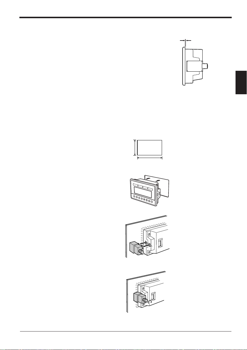
Panel mounting
2. Overview and Operation
■ Precautions
• Install the KV-D20 by holding the panel at
1.2 to 3.0 mm
the front and rear sides with the unit and
mounting fixtures.
Available panel thickness: 1.2 mm to 3.0
mm
* If your panel has a thickness of 3.0 mm
or more, contact your nearest KEYENCE
office listed at the back of this manual.
• To ensure maintainability, operability, and ventilation, keep as much distance as
possible between the KV-D20 and the surrounding structure or components.
• Prevent the KV-D20 from being heated by the heat released by other devices.
• Install the KV-D20 as far as possible from devices that may generate arcs (e.g.
electromagnetic switches, no-fuse circuit breakers, etc.).
■ Mounting method
1. Cut an opening with the following dimensions in the panel to mount the KV-D20.
+1
68
0
+1
105
2. Insert the KV-D20 through the opening from the front surface of the panel.
0
2
76543210
3. Secure the KV-D20 to the panel with the mounting fixtures.
4. Tighten the screws of the fixtures. [Tightening torque: 0.2 N•m (2 kgf•cm) max.]
13
Page 14

2. Overview and Operation
1.5 Inspection and Maintenance
This section describes how to inspect and maintain the KV-D20.
Inspection
The KV-D20 may cause malfunctions due to loose modular cable connectors or
mounting fixtures during long-term use.
Be sure to regularly check the KV-D20 unit and connections.
The major items to check are as follows:
2
Maintenance
CAUTION
• Are the modular cable connectors disconnected or loosened?
• Are the mounting fixtures of the KV-D20 detached or loosened?
Dust adheres to the KV-D20 during long-term use.
Wipe the dust off using a clean dry cloth.
If dust or dirt adheres to a small part, wipe it off using a cotton swab.
Be sure to turn off the KV-D20 before inspection or maintenance.
14
Page 15

2. Overview and Operation
2.1 Use Examples for the KV-D20
This section includes examples of uses for the KV-D20.
As a handheld programmer
The KV-D20 allows you to change the KV series’ operating mode (RUN or PROGRAM) or to change the preset values of timers and counters without using the
KV-P3E(01) handheld programmer.
As a digital switch
Various values can be input with the KV-D20. You can directly change the values
of desired devices without using ladder programs.
Moreover, the KV-D20 can be connected with a cable instead of the I/O unit, so
that the amount of wiring and I/O points can both be reduced.
As a display unit
The KV-D20 can display the number of products or the tact time. Since the KV-D20
can be connected with a cable instead of the I/O unit, the amount of wiring and I/O
points can both be reduced.
As a device to give instructions to workers
When using a rotating beacon, the occurrence of an error can be noted but the
contents of the error, such as a clogged workpiece, missing workpiece, or product
changeover, may often be unclear.
The KV-D20 features a user message function. By using the function, work efficiency can be greatly improved.
A beep function is also available to indicate errors with sound.
2. Overview and Operation
2
15
Page 16
2. Overview and Operation
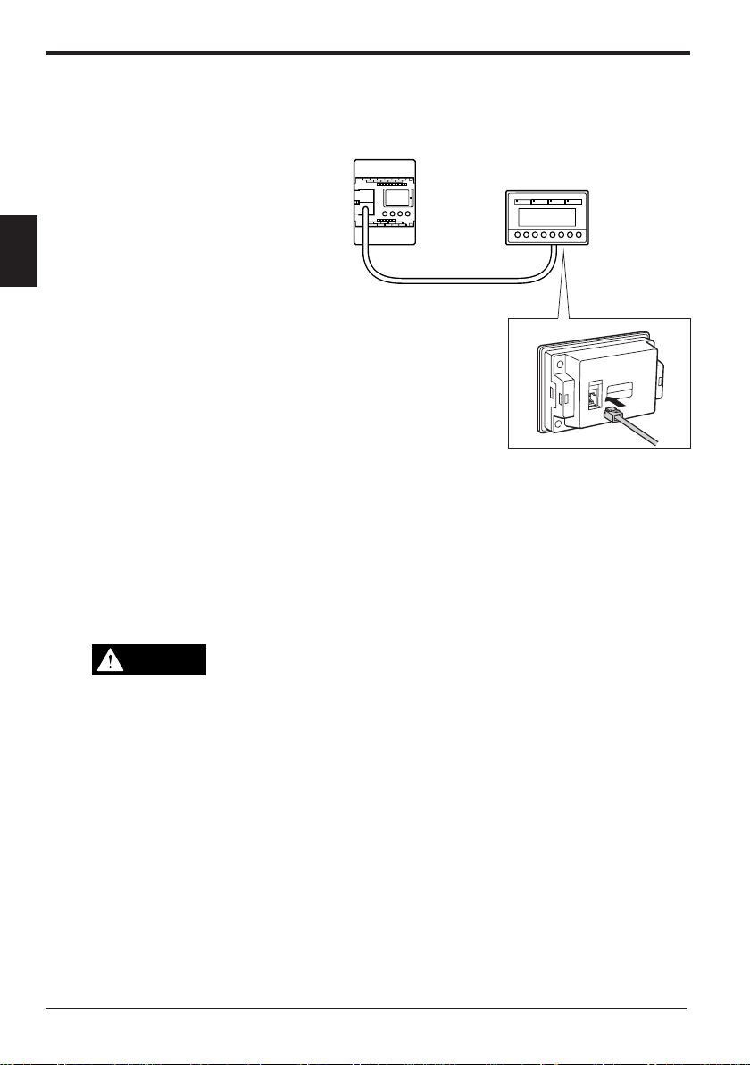
2.2 Connection with the KV Series
This section describes how to connect the KV-D20 with the KV Series.
Connection
Open the connector
cover of the KV basic
unit and connect the
modular connector
supplied with the KVD20. (Either communi-
2
Precautions
WARNING
cation port A or B can
be used.)
• Connecting/disconnecting the modular cable can be done at any time regardless of whether the KV unit is turned on or off.
• Both communication ports A and B can be used to connect the KV-D20. However, do not connect two KV-D20s at the same time.
• When connecting the KV-P3E(01) handheld programmer to a KV Series that is
already connected to the KV-D20, set the mode selector switch of the KVP3E(01) to "PROGRAM" before connecting it. Do not connect the KV-P3E(01)
to the KV series together with the KV-D20 for a long period of time.
• Never tie the modular cable together with or route it close to strong electrical lines or output lines. This will cause damage to the KV-D20.
• Prevent a strong force from being applied to the modular cable.
• Be sure to use the modular cable specified by KEYENCE (OP-26487,
supplied with the KV-D20). Use of an unspecified cable may cause malfunctions.
• The modular cable cannot be extended.
Modular cable (2.5 m)
Insert the other end of the modular
cable to the communication port at
the rear of the KV-D20.
16
Page 17
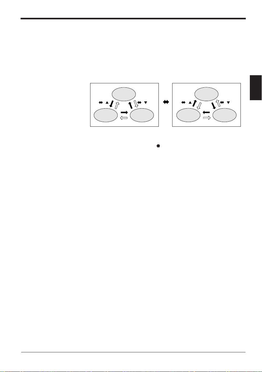
2.3 Overview of the KV-D20
+ + ++
The KV-D20 has three display modes: operator mode, device mode, and system
mode. This section includes an overview of these modes.
Switching the display mode
The KV series has two operating modes: RUN and PROGRAM.
The KV-D20 allows changes among the operator mode, device mode, and system
mode for the RUN and PROGRAM modes respectively.
RUN mode
Operator
mode
2. Overview and Operation
PROGRAM mode
Operator
mode
2
Device mode
Customized switches F1 through F4 and customized lamps 1 through 4 can be
used in all modes.
To lock the display screen, press the
seconds to set/reset the key-lock function.
Changes between display modes can be limited by setting special utility relays
2508 and 2509 and data memory DM1676.
➮
Refer to "Screen change function" on page 22.
System mode
Device mode
and ▲ (▼) keys simultaneously for three
System mode
17
Page 18

2. Overview and Operation
Overview of each display mode
2
This section includes an overview of the three display modes: operator mode,
device mode, and system mode.
■ Operator mode
Normally, operators use this mode. It includes the following five screens:
• Operator screen (
Allows you to display five pages (20 lines/page) of devices by writing simple
ladder programs. Contact comments that are entered with alphanumeric characters can also be displayed. Each device can be displayed along with various
attributes.
• Direct access screen (
This screen corresponds to the digital trimmer mode of the Access Window of
the KV unit. Values in three DM (DM1677, DM1678, and DM1679) can be
changed in real time.
• KV-I/O monitor screen (
Allows simultaneous monitoring of two channels (8 bits x 4 lines) for the I/O
status and unit connection information for the KV series I/O devices.
• Switch comment screen (
Displays the contact comments for relays (2500 to 2503) assigned to four builtin customized switches (F1 to F4) of the KV-D20, provided that the comments
are entered with alphanumeric characters.
• Lamp comment screen (
Displays the contact comments for relays (2504 to 2507) assigned to four builtin customized lamps (Lamp 1 to Lamp 4) of the KV-D20, provided that the
comments are entered with alphanumeric characters.
■ Device mode
This mode corresponds to the device mode of the Access Window of the KV unit.
Allows you to display or change all device values (The digital trimmer value cannot
be changed.).
■ System mode (
This mode corresponds to the system mode of the Access Window of the KV unit.
Allows you to switch the KV unit between RUN and PROGRAM modes using the
KV-D20. However, LOAD/SAVE functions using EEPROM are not available.
(➮ page 25)
➮
page 26
➮
page 34
➮
(➮ page 38)
➮
page 42)
)
page 35
➮
page 36
➮
page 36
)
)
)
)
18
Page 19
Assignment of relays/DM
In the KV series, special utility relays 2500 through 2513, DM1580 through 1599,
and DM1670 through 1699 are the devices relevant to the KV-D20. The devices
are assigned as follows:
■ Special utility relays used for the KV-D20
.oNyaleRnoitcnuF
0052 .yalersihtnosnrut)1hctiwsdezimotsuC(1FgnisserP
1052 .yalersihtnosnrut)2hctiwsdezimotsuC(2FgnisserP
2052 .yalersihtnosnrut)3hctiwsdezimotsuC(3FgnisserP
3052 .yalersihtnosnrut)4hctiwsdezimotsuC(4FgnisserP
4052 .NOsiyalersihtnehwsetanimulli1pmaL
5052 .NOsiyalersihtnehwsetanimulli2pmaL
6052 .NOsiyalersihtnehwsetanimulli3pmaL
7052 .NOsiyalersihtnehwsetanimulli4pmaL
8052
9052
0152
1152 .NOsiyalersihtnehwsdnuospeebA:gnittespeeB
3152
5152 elbasiD:FFO,elbanE:NO:)0591MD(yalpsidegassemresU
elbanE:NO,elbasiD:FFO
elbanE:NO,elbasiD:FFO
02D-VKfognittesteseR
.tesersi02D-VK
2. Overview and Operation
2
:edomeciveddnaedomrotareponeewtebegnahC
.edomecivedotsegnahcselbasidgnitteslaitiniehT
:edommetsysdnaedomrotareponeewtebegnahC
:segassemmetsysrofegaugnalyalpsiD
.hsilgnEsignitteslaitiniehT
)anakatak(esenapaJ:NO,hsilgnE:FFO
.edommetsysotsegnahcselbasidgnitteslaitiniehT
.noissimrepegnahcneercssahcusegnahcatcelferyletaidemmiotdesU
ehtnehwyllacitamotuaffosnruT.NOsiyalersihtnehw02D-VKehtsteseR
Note: To set special utility relay 2513 to reset the KV-D20, turn on (SET) 2513 for
one scan as shown below. The relay is automatically turned off after the KV-D20 is
reset.
1000
XXXX 1000
DIFU
2513
SET
xxxx: Condition (Trigger input)
■ Data memory used for the KV-D20
.oNMDnoitcnuF
ot0851MD
9951MD
ot0761MD
5761MD
6761MD .edomrotareponiegnahcneercsstimreP
ot7761MD
9761MD
ot0861MD
9961MD
0591MD .secivedyalpsidegassemresuseificepS
metsysrofdevreseR
neercssseccatceridrofdesU
)enilht02oteniltsrif(deyalpsidebotrebmuneciveD
)enilht02oteniltsrif(eciveddeyalpsidfosetubirttA
19
Page 20
2. Overview and Operation
Other functions
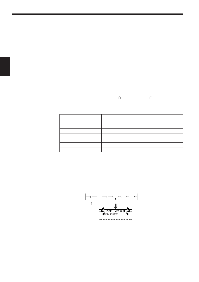
User message function
2
This section describes other functions of the KV-D20.
This function corresponds to the user message function of the Access Window of
the KV unit. The Access Window displays numeric values only, but the KV-D20
displays comments as well.
Messages are displayed with 32 characters (16 characters x 2 lines).
The Access Window displays the desired number stored in DM1950 when a certain
relay turns on. However, the KV-D20 displays the contact comment for the device
specified with the value stored in DM1950, in the same manner as the operator
screen.
Note that although the KV unit is running, the Access Window does not display the
correct value while the user message is displayed.
To cancel the user message, press the
key. (Pressing the key is effective
even while the key-lock function is set.)
■ Type of device to be displayed
remiT )942ot0(T94202ot00002
CTC )3ot0(30022ot00022
HTC )1,0(10032ot00032
yaleR )51971ot0(YLR51975ot00004
eciveDeulavdnarepOeulavgnittes0591MD
retnuoC )942ot0(C94212ot00012
yromematadyraropmeT )13ot0(MT13042ot00042
yromemataD )9991ot0(MD99913ot00003
Note: Do not enter a value in DM1950 other than those above.
Example
When the value specifying a certain relay is stored in DM1950 and the relay turns
on, the comment for the relay is displayed on the KV-D20 screen.
The following ladder program displays the message "Add screws" when relay 0001
turns on.
Specified
relay
1000
1000
DIFU
0001
"ADD SCREW"
Contact comment
#40001
LDA
Instruction to display comment for relay 0001
2515
DM1950
SET
STA
[RLY0001 turns on]
20
Note 1: To enter a space to the left of a contact comment, input "~" (swung dash)
at the left end of the comment with the LADDER BUILDER for KV. Spaces without
"~" at the left end will be ignored. Please note when "~" is used in the middle of a
contact comment, it is displayed as "➞".
Note 2: Contact comments can be displayed only when the LADDER BUILDER for
KV Ver. 1.5 or later is used and the compression transfer of contact comments is
not selected.
Page 21
2. Overview and Operation
Note 3: Even the contact comments for ladder programs created with LADDER
BUILDER for KV Ver. 1.0x or KV-LADDER can be displayed on the KV-D20 after
being transferred to the KV unit with the LADDER BUILDER for KV Ver. 1.5 or
later.
Note 4: "Not transfer" is initially set as the contact comment transfer setting of the
LADDER BUILDER for KV Ver. 1.5 or later. To display contact comments on the
KV-D20, enable the contact comment transfer setting with the LADDER BUILDER
for KV Ver. 1.5 or later.
➮
Refer to the NEW KV Series User's Manual "Chapter 6 Software-Windows [KV-H6WE2]" on page
195.
When a system error occurs
Display language selection
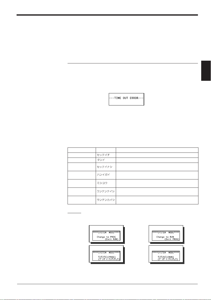
The KV-D20 monitors only the communication status with the KV series.
When a system error occurs or communication is disabled in the KV unit, the KVD20 displays the message "TIME OUT ERROR".
The KV-D20 allows language selection from "English" or "Japanese" for the messages defined by the system of the KV series. The initial setting is English (Refer to
the table below).
To switch the display to Japanese, turn on special utility relay 2510.
hsilgnEesenapaJnoitpircseD
TESERP retnuocroremitafoeulavteserP
CED/CNI neercssseccatceridrofytitnauq)tnemerced(tnemercnI
MARGORPON
EGNARFOTUO
DESUNU
GORPotegnahC
)NURtixE(
NURotegnahC
)GORPtixE(
.yromem
.egnarelbaliava
.yromematadretalro0851MD
edommetsysniGORPotNURmorfsegnahcneercS
edommetsysniNURotGORPmorfsegnahcneercS
Example
Display in system mode
RUN mode
English display
PROG mode
English display
2
atadretalro0851MDotdeificepssi)0eulavro(gnihtoN
fotuosiyromematadretalro0851MDrofeulavteserP
otdeificepssiretnuocdeeps-hgih/retnuoc/remitdesunU
Japanese display
Japanese display
21
Page 22
2. Overview and Operation
Beep function
The KV-D20 features a beep function to provide an audio signal for workers.
The beep sounds while special utility relay 2511 is turned on.
2
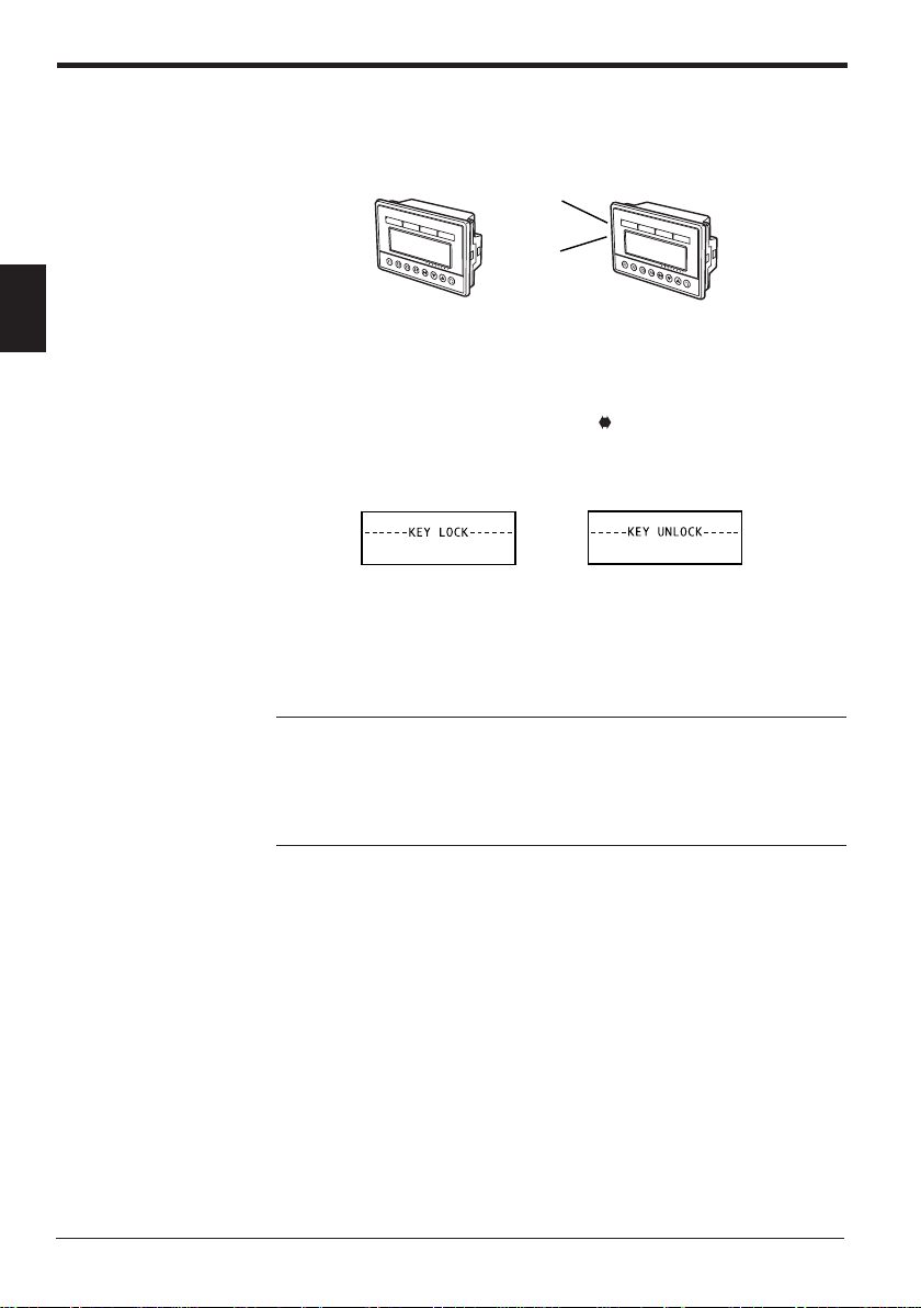
Key-lock function
Screen retention function
2511 is OFF.
Beep
The key-lock function is used to lock the display screen.
When the key-lock function is set, the current screen is locked regardless of the
display screen mode or status.
To set or reset the key-lock function, press the
for three seconds.
The key-lock setting is retained even when the KV-D20 is turned off once and on
again.
Key-lock
When the KV-D20 is turned on again, it shows the last screen displayed before the
power was turned off.
However, the decimal/hexadecimal notation setting in device mode is not retained.
Decimal notation is used when the KV-D20 is turned on again.
Note 1: The status of the KV-D20 is retained by the KV unit.
Note 2: The status of the KV-D20 is retained only for the memory backup period of
the KV unit.
Note 3: To retain the status longer, select "SAVE" in the system mode of the
Access Window of the KV unit.
➮
Refer to "LOAD mode and SAVE mode" on page 4.
2511 is ON.
and ▲ (▼) keys simultaneously
Key-unlock (reset)
Screen change function
22
Setting special utility relay 2508 to "ON" enables switching between the operator
mode and the device mode. Setting special utility relay 2509 to "ON" enables
switching between the operator mode and the system mode.
Setting each bit of DM1676 to "ON" enables the screen change in the operator
mode. The initial setting (DM1676 = #00000) only allows switching between the
operator, switch comment, and lamp comment screens.
When changing the current mode (screen) is disabled during operation, the setting
becomes effective after the current mode (screen) is changed to another mode
(screen). To activate the setting immediately, turn on special utility relay 2513. The
mode is switched to the operator mode when the setting of special utility relays
2508 or 2509 is changed. The mode is switched to the next available mode when
the setting of data memory DM1676 is changed.
Page 23

6761MDedoM
0tiB neercsrotarepO
1tiB )7761MD(neercssseccatceriD
2tiB )8761MD(neercssseccatceriD
3tiB )9761MD(neercssseccatceriD
4tiB neercsrotinomO/I-VK
5tiB neercstnemmochctiwS
6tiB neercstnemmocpmaL
* Enter "0" in Bits 7 and following.
2. Overview and Operation
Note: To set special utility relay 2513 to reset the KV-D20, turn on (SET) 2513 for
one scan as shown below. The relay is automatically turned off after the KV-D20 is
reset.
Precautions about screen change function
Disabling mode (screen) change setting
Do not disable the mode (screen) change setting during operation.
■ When change setting is disabled for the current mode (screen):
The setting is not effective until the current mode (screen) is changed to another
mode (screen).
To activate the setting immediately, turn on special utility relay 2513 for one scan.
Note: To set special utility relay 2513 to reset the KV-D20, turn on (SET) 2513 for
one scan as shown below. The relay is automatically turned off after the KV-D20 is
reset.
When the setting is activated in the operator mode, the screen is switched to the
next available screen.
For example, when the screen change is set to the operator screen, KV-I/O monitor
screen, or switch comment screens while the direct access screen (DM1677) is
displayed, the screen is switched to the KV-I/O monitor screen after the setting is
activated.
egnahcforedrOneercS
0 neercsrotarepO
1 )7761MD(neercssseccatceriD
2 )8761MD(neercssseccatceriD
3 )9761MD(neercssseccatceriD
4 neercsrotinomO/I-VK
5 neercstnemmochctiwS
6 neercstnemmocpmaL
When special utility relay 2508 is turned off in the device mode or special utility
relay 2509 is turned off in the system mode and the setting is activated, the current
mode is switched to the operator mode.
* When the operator screen is displayed, the screen change setting is not acti-
vated unless it is changed to another screen with the
▼ key only to change pages does not activate the screen change setting.
1000
XXXX 1000
DIFU
1000
XXXX 1000
DIFU
2513
SET
xxxx: Condition (Trigger input)
2513
SET
xxxx: Condition (Trigger input)
2
key. Pressing the ▲ or
23
Page 24

2. Overview and Operation
■ When change setting is disabled for the current mode (screen) and the
KV-D20 is turned off:
The setting is activated when the KV-D20 is turned on again. The screen next to
the disabled screen appears.
■ When change setting is disabled to a mode (screen) other than the current
mode (screen):
The change to the specified mode (screen) is disabled. The mode (screen) is not
displayed when screens are switched.
Process when the KV unit status is changed
2
When a ladder program is written to the KV unit or the unit is switched to PROGRAM mode, the contents of special utility relays 2500 through 2515 are processed as shown below.
.nettirw
.nettirwsi
tinuVKninoitarepO
dnadeppotssiVKehT
simargorpreddala
noitareponisiVKehT
margorpreddaladna
ottessiVKehT
.etatsMARGORP
syaleR
5152ot0052
deraelC
deniateR
deniateR
.edomrotarepo
noitpircseD
ecivedehtnidemrofrepsinoitareposihtnehW
otdecrofsineercseht,edommetsysroedom
enoehtsaemasehtsineercstnerrucehT
simargorpreddalehterofebdeyalpsid
edomtnerrucehtotegnahcehtnehW.degnahc
ehtretfadetavitcasignitteseht,delbasidsi
.edomrehtonaotdegnahcsiedomtnerruc
.etatsNURnisaemasehtsi
gnittesegnahcneercsdnaneercstnerrucehT
24
Page 25

2.4 Operator Mode
The operator mode has five screens: operator screen, direct access screen,
KV-I/O monitor screen, switch comment screen, and lamp comment screen.
This section includes an overview and description of operation of each screen.
Screen selection in operator mode
Press the key to select screens in the operator mode.
The screens are changed in the following order.
0 neercsrotarepO
1 )7761MD(neercssseccatceriD
2 )8761MD(neercssseccatceriD
3 )9761MD(neercssseccatceriD
4 neercsrotinomO/I-VK
5 neercstnemmochctiwS
6 neercstnemmocpmaL
* The operator screen appears after the lamp comment screen.
It is necessary to turn on the bit of the desired screen to enable selection in
DM1676.
➮
Refer to "Screen change permission in operator mode" on page 37.
The initial setting allows switching between the operator, switch comment, and
lamp comment screens only.
egnahcforedrOedoM
Operator screen (initial screen)
➮
Page 26
DEFECTIVE: 20PCS
PRODUCED: 456
PRESET CNT: 1000
RLY00010 ON
2. Overview and Operation
2
Direct access screen
➮
Page 34
PROCESS SPEED1: 25
PROCESS SPEED3: 25
(DM1677)
(DM1678)
(DM1679)
KV-I/O monitor screen
➮
Page 35
LED1:MOTOR A RUNNING
LED2:MOTOR B RUNNING
LED3:RLY 2506
LED4:RLY 2507
Switch comment screen
➮
Page 36
F1:MOTOR A START
F2:MOTOR A STOP
F3:RLY 2502
F4:RLY 2503
Lamp comment screen
➮
Page 36
25
Page 26

2. Overview and Operation
*3
*2
*1
1DEFECTIVE: 10PCS
PRODUCED: 456
PRESET: 1000
RLY 00010 ON
2DEFECTIVE: 20PCS
PRODUCED: 456
PRESET: 1000
RLY00060 ON
3DEFECTIVE: 30PCS
PRODUCED: 456
PRESET: 1000
RLY 00020 ON
4DEFECTIVE: 30PCS
PRODUCED: 456
PRESET: 1000
RLY 00020 ON
5DEFECTIVE: 30PCS
PRODUCED: 456
PRESET: 1000
RLY 00020 ON
1DEFECTIVE: 10PCS
PRODUCED: 456
PRESET: 1000
RLY 00010 ON
1DEFECTIVE: 10PCS
PRODUCED: 456
PRESET: 1000
RLY 00010 ON
1DEFECTIVE: 10PCS
PRODUCED: 456
PRESET: 1000
RLY 00010 ON
1DEFECTIVE: 10PCS
PRODUCED: 456
PRESET: 1000
RLY 00010 ON
1DEFECTIVE:
PRODUCED:
PRESET:
RLY 00010
1DEFECTIVE:
PRODUCED:
PRESET:
RLY 00010
1DEFECTIVE:
PRODUCED:
PRESET:
RLY 00010
Operator screen
2
Devices and their attributes can be easily displayed on the KV-D20.
Canceled when is pressed or
when no key is pressed for 25
seconds
x
1.5 sec.
• Press the ▲ or ▼ key to select the device to
change its value.
• Only the items that can be changed will flash.
• Press the ▲ or ▼ key to switch pages.
• Up to 5 pages can be displayed.
Normal mode
26
Numeric value change mode
Customized switches F1 through F4 and customized lamps 1 through 4 can be
used in all modes.
To lock the display screen, press the
seconds to set/reset the key-lock function.
and ▲ (▼) keys simultaneously for three
Page 27

2. Overview and Operation
1DEFECTIVE: 10PCS
PRODUCED: 456
PRESET: 1000
RLY 00010 ON
1DEFECTIVE: 10PCS
PRODUCED: 456
PRESET: 1000
RLY 00010 ON
1DEFECTIVE: PCS
PRODUCED: 456
PRESET: 1000
RLY 00010 ON
Canceled when
or when no key is pressed
for 25 seconds.
1DEFECTIVE: 10PCS
PRODUCED: 456
PRESET: 1000
RLY 00010 ON
1DEFECTIVE: 10PCS
PRODUCED: 456
PRESET: 1000
RLY 00010 ON
1DEFECTIVE: 01010PCS
PRODUCED: 456
PRESET: 1000
RLY 00010 ON
• Press the key to move through digits.
• Press the s or t key to increment/decrement a value.
• Digits do not shift automatically.
*1. Select the page of the device to change its value and enter the change mode. (The line flashes.)
*2. A line does not flash if it is set to disable the value change by the device attribute display setting. If
all lines are set to disable the value change, no line flashes.
➮
Refer to "Device attribute display setting" on page 30.
*3. The value section of the device flashes. (The zero suppression is canceled. The leftmost digit
flashes.)
*4. Confirm the new value.
is pressed
1DEFECTIVE: 9010PCS
*4
PRODUCED: 456
PRESET: 1000
RLY 00010 ON
x
1.5
sec.
2
27
Page 28

2. Overview and Operation
Device display setting
2
Set the desired device to be displayed on the screen to DM1580 (first line) through
DM1599 (20th line) with the setting number according to the following table.
■ Type of device to be displayed
eciveDeulavdnarepOeulavgnittes9951-0851MD
remiT )942ot0(T94202ot00002
retnuoC )942ot0(C94212ot00012
CTC )3ot0(30022ot00022
HTC )1,0(10032ot00032
yromemataD )9991ot0(MD99913ot00003
yaleR )51971ot0(YLR51975ot00004
• When the change to the operator screen is enabled but no value is entered in
DM1580 through DM1599, "NO PROGRAM" is displayed.
• For example, enter "#30003" to specify DM0003, and "#40010" to specify input
relay 00010.
• The device specified for DM1580 is the one displayed on the first line, and the
device specified for DM1581 is the one displayed on the second line.
• When no device is specified for a certain DM, the line of the DM is displayed as
blank.
yromematadyraropmeT )13ot0(MT13042ot00042
Example
When devices are specified for DM1584 and following, the first page is displayed as blank.
• Timers and counters are displayed using two lines because preset values
shown with "PRESET" are also displayed (initial setting). The preset value
display can be hidden by the device attribute display setting.
➮
Refer to "Device attribute display setting" on page 30.
• Devices can be displayed for as many as five pages (4 lines x 5 pages = 20
lines). The number of devices is reduced when some devices, such as timers
and counters, use two lines. For example, when only timers and counters are
specified, up to 10 devices can be displayed.
• If a device that uses 2 lines is specified on the fourth line of a page, the fourth
line is left blank and the current and preset values are displayed on the first line
of the next page.
If a device that uses 2 lines is specified on the 20th line, it is canceled.
First page
Second page
28
The fourth line is left blank.
• If a timer, counter, or high-speed counter that is not described in a ladder
program is specified, "UNUSED" is displayed.
Page 29

Displaying contact comments
• The contact comments for the specified devices are displayed from the left end,
• Up to 20 characters can be displayed for a comment. The 21st and following
• If a numeric value and a comment overlap, the numeric value has priority to be
• If a device has no contact comment, the device number is displayed.
• If a contact comment is changed and transferred to the KV unit, disconnect the
Note 1: To enter a space to the left of a contact comment, input "~" (swung dash)
at the left end of the comment with the LADDER BUILDER for KV. Spaces without
"~" at the left end will be ignored. When "~" is used in the middle of a contact
comment, it is displayed as "➞".
Note 2: Contact comments can be displayed only when the LADDER BUILDER for
KV Ver. 1.5 or later is used and the compression transfer of contact comments is
not selected.
Note 3: Even the contact comments for ladder programs created with LADDER
BUILDER for KV Ver. 1.0x or KV-LADDER can be displayed on the KV-D20 after
being transferred to the KV unit with the LADDER BUILDER for KV Ver. 1.5 or
later.
Note 4: "Not transfer" is initially set as the contact comment transfer setting of the
LADDER BUILDER for KV Ver. 1.5 or later. To display contact comments on the
KV-D20, enable the contact comment transfer setting with the LADDER BUILDER
for KV Ver. 1.5 or later.
➮
2. Overview and Operation
provided they are set with alphanumeric characters. However, only comment 1
is displayed.
characters are not displayed.
displayed.
communication cable of the KV-D20 once and connect it again. This updates
the display.
Refer to the NEW KV Series User's Manual "Chapter 6 Software-Windows [KV-H6WE2]" on page
195.
2
29
Page 30

2. Overview and Operation
Device attribute display setting [DM1680 (first line) through DM1699 (20th line)]
The KV-D20 allows the display of devices with desired attributes.
When no attributes are specified, the initial setting is used.
The following 10 attributes can be specified using hexadecimal numbers for each
line.
$ ■■■■■■■■
▲
2
▲
▲
▲
.oNsetubirttA
stiB
3ot0
stiB
7ot4
8tiB seulavciremunedih/wohS
9tiB sngisedih/wohS.sngisediH.sngiswohS
01tiB stibfo.oNstib61stib23
11tiB noitatoNlamiceDlamicedaxeH
21tiB seulavteserpedih/wohS.seulavteserpwohS.seulavteserpediH
31tiB gnittesnoisserppus-oreZ.noisserppusorezesU
41tiB
51tiB
noitisoptnioplamiceDtnioplamicedoN
thgirehtotsecapsfo.oN
seulavciremunfo
seulavteserp
gnignahcelbasid/elbanE
gnignahcelbasid/elbanE
seulav)tnerruc(
*)FFO(0)NO(1
thgir-hsulF)F(51ot0:secapsfo.oN
.seulavciremun
elbanEelbasiD
elbanEelbasiD
* 0 is initial setting.
■ Decimal point position (Bits 0 to 3) [Initial setting: 0 (No decimal point)]
• Specify the number of digits to the right of the decimal point.
• The position of the decimal point can be set within the maximum number of
digits to be displayed. The setting of a larger value is ignored.
Example
When the number of bits is set to 16 bits, the maximum number of digits is 5, so
that the decimal point position can be set between 0 and 5. Values larger than 5
are regarded as 5.
• The decimal point is fixed at the specified position.
• Values between 0 through 15 can be used (4-bit binary).
• If a device has a preset value such as counters and timers, the decimal point is
also set to the preset value at the same position as the current value.
• If a device has no numeric values to the left of the decimal point, "0." is displayed.
Example
When a decimal point position is specified at the third digit from the right, value
"123" is displayed as "0.123".
Example
Bits: 15 14 13 12 11 10 9 8 7 6 5 4 3 2 1 0
Setting: 10100001
$ 10(A) 1 4 2
* 2 digits are displayed in the right of decimal point.
* 4 digits of spaces are placed in the right of value.
noitcnufdnaeulavteS
)F(51ot0
dnastnemmocwohS
:noitisoptnioplamiceD
.ylnostnemmocwohS
orezesutonoD
.noisserppus
30
Page 31

2. Overview and Operation
■ Number of spaces to the right of a numeric value (Bit 4 to 7)
• Normally, numeric values are displayed from the right end. Setting the number
of spaces to the right of a numeric value changes the position of the numeric
value as desired.
Note: The position of the PRESET value cannot be changed.
• Values from 0 through 15 can be used (4-bit binary).
However, the maximum number of spaces is the one at which the maximum
value is left flush. The number of spaces is not increased even when a larger
number is specified.
Example
When the device display is set to 16 bits with signs, the allowable number of
spaces is obtained in the following equation:
• Carefully selecting the number of spaces to the right of a numeric value and the
comment results in an easy-to-see display.
Example
"_" represents a space.
Comment: "DEFECTIVE:_ _ _ _ _ _ _ _PACKS"
Number of spaces to the right of a numeric value: 5
Displayed comment: "DEFECTIVE:_ _ _ _ _123PACKS"
As shown above, the comment can be added at the end of the numeric value,
improving visibility.
■ Show/hide numeric values (Bit 8)
Specify whether or not to display a numeric value on each line.
• To display only the comment on a line, turn on Bit 8.
• Even when Bit 8 is on, PRESET is displayed for devices using two lines (timers
and counters). To hide the PRESET display, turn on Bit 12 (Show/hide preset
value).
[Initial setting: 0 (No spaces on the right end)]
20 - 5 - 1 = 14
↓
↑↑
Sign
5 spaces
Number of digits of
numeric value
Number of spaces is limited to 14 even when "15" is specified.
[Initial setting: Show comment and numeric value]
2
■ Show/hide signs (Bit 9) [Initial setting: Hide signs]
Specify whether or not to display signs for the displayed value.
• To display a minus sign, turn on Bit 9.
• The value is processed with two’s complement number and displayed with a
negative sign.
Example
"#65535" is displayed as "-1".
•A negative sign is displayed to the left of the numeric value. (The sign shifts its
position as the number of digits increases.)
31
Page 32

2. Overview and Operation
2
■ Number of bits (Bit 10) [Initial setting: 16 bits]
Specify the number of bits to be used to display the numeric value.
• To display a value with 32 bits, turn on Bit 10.
• The 32-bit display is available only for devices TM and DM.
• When 32-bit display is set, the specified device is displayed in low-order bits,
and the device that has the next device number of the specified device is
displayed in high-order bits.
• Devices CTC and CTH can be displayed with 24 bits, which is specified with the
MEMSW instruction. (In this case, the Bit 10 setting is ignored.)
■ Notation (Bit 11) [Initial setting: Decimal]
Specify the notation used for the numeric value to be displayed.
• To select hexadecimal notation, turn on Bit 11.
• In the hexadecimal notation, "$" is prefixed to the numeric value and the zerosuppression function is disabled.
• If a device has a preset value such as timers and counters, the same notation is
used for both the preset value and the current value.
• The initial setting for relay is turning on/off one bit. When Bit 11 is ON, the
status of eight bits is displayed collectively. These eight bits cannot be turned
on or off.
• When eight bits are displayed collectively, relays of eight bits starting from the
specified relay are displayed.
Example
When relay 00502 is specified, the status of relays 00502 through 00509 is
displayed from the right end.
Decimal display
Hexadecimal display
8-bit ON/OFF indication
32
■ Show/hide preset values (Bit 12) [Initial setting: Show preset values]
Specify whether or not to display a preset value when the device has a preset
value such as timers and counters.
• To hide the preset value, turn on Bit 12.
■ Zero-suppression setting (Bit 13) [Initial setting: Use zero suppression]
Specify whether or not to use the zero-suppression function for the displayed
preset value.
• To disable the zero-suppression function, turn on Bit 13.
■ Enable/disable changing preset values (Bit 14) [Initial setting: Enable]
If a device has a preset value such as timers and counters, specify whether or not
to change the preset value with the KV-D20.
• To disable changes, turn on Bit 14.
■ Enable/disable changing (current) values (Bit 15) [Initial setting: Enable]
Specify whether or not to change the currently displayed value with the KV-D20.
• To disable changes, turn on Bit 15.
Page 33

Priority of attribute display (except for Bits 14 and 15)
1. Show/hide numeric value
2. Notation
3. Others
Note 1: When "Show/hide numeric value" is set to OFF (Bit 8 is ON), the numeric
value is not displayed even if other bits are turned ON. Only comments are displayed. However, the display of the preset value for a device using two lines
(timers and counters) depends on the Bit 12 setting.
Note 2: When "Notation" is set to "hexadecimal" (Bit 11 is ON), the decimal point,
zero-suppression, and sign settings are ignored even if they are specified.
Cautions about the numeric value change mode
• Numeric values can be changed when the KV is in both RUN and PROGRAM
modes.
• The KV-D20 automatically exits the numeric value change mode and returns to
the normal mode when no keys are pressed for approximately 25 seconds. In
such a case, the value being changed is canceled.
• Even if the zero-suppression function is specified in the normal mode, the
function is canceled in the numeric value change mode. In such a case, some
comments may be hidden by zeros.
•A line does not flash if it is set to disable the value change by the device attribute display setting. If all lines are set to disable the value change, no line
flashes.
➮
Refer to "Device attribute display setting" on page 30.
• After values are changed, it takes "one scan + 100 ms" at maximum until the
change is reflected.
• All contents of the displayed devices are not actually changed while the KV-D20
is in the numeric value change mode. The contents are updated after the KVD20 returns to the normal mode.
• Do not change the ladder program in the KV while the numeric value is changed
with the KV-D20.
• Values outside of the available setting range cannot be entered.
Error messages
The following table shows the error messages that may appear during the display
setting of DM1580 through DM1599.
egasseMnoitpircseD
MARGORPON .deificepssignihtoN
EGNARFOTUO .egnarelbaliavaehtfotuosieulavdeificepS
DESUNU .deificepssiretnuocdeeps-hgih/retnuoc/remitdesunU
* For other devices, their values are displayed even if they are not used.
2. Overview and Operation
2
33
Page 34

2. Overview and Operation
Direct access screen
2
This screen corresponds to the digital trimmer mode of the Access Window of the
KV unit. Values in DM1677, DM1678, and DM1679 can be changed in real time.
Operator screen
PROCESS SPEED: 11
KV-I/O monitor screen
Select the device to be changed
from the three devices.
• Press the
(1, 10, 100, 1000, and 10000)
• Press the ▲ or ▼ key to increment/decrement a value.
(0 to 65535)
• Digits are shifted automatically.
key to select the increment/decrement quantity.
Numeric value change mode
Customized switches F1 through F4 and customized lamps 1 through 4 can be
used in all screens.
To lock the display screen, press the
and ▲ (▼) keys simultaneously for three
seconds to set/reset the key-lock function.
• You can set the DM to be used for direct access in DM1676.
➮
Refer to "Screen change permission in operator mode" on page 37.
• Values can be changed to between 0 and 65535.
• When a contact comment is specified, the comment is displayed.
• Pressing the
key changes the screen from [Operator screen], [Direct access
screen: DM1677], [Direct access screen: DM1678], [Direct access screen:
DM1679], to [KV-I/O monitor screen].
• The specified increment/decrement quantity is stored until the KV-D20 is turned
off.
Note 1: Numeric values can be changed when the KV unit is in both RUN and
PROGRAM modes.
Note 2: After the current value of DM is changed, it takes "one scan + 100 ms" at
maximum until the change is reflected.
34
Page 35

KV-I/O monitor screen
2. Overview and Operation
Allows simultaneous monitoring of two channels (8 bits x 4) for the ON/OFF status
of the input (IN), output (OUT), and connection information (USE) of the KV series
I/O devices.
■
" represents the ON status, and "_" represents the OFF status.
"
Bits are assigned from right to left: bits 0 through 7 on "L" lines, and bits 8 through
15 on "H" lines.
• Press the ▲ or ▼ key to select the
device number (IN, OUT, or USE).
Holding down the ▲ or ▼ key lets the screen scroll faster (turbo function). However, in the turbo mode, the screen does not show the ON/OFF status but shows
only device numbers.
Customized switches F1 through F4 and customized lamps 1 through 4 can be
used in all modes.
To lock the display screen, press the
seconds to set/reset the key-lock function.
➮
Refer to the table below for the information displayed on the KV-I/O monitor screen.
)seireS(ledoMnoitamrofninoitcennoC.oNMD/yaleR
O/I
* The initial setting displays "RLY00000" (KV-40: "RLY00100") for "I/O-IN",
"RLY00500" for "I/O-OUT", and "DM1937" for "I/O-USE".
The relays for the expansion unit (RLY00100 to 00415, RLY00600 to 00915)
are displayed only when the corresponding expansion unit is connected.
NI51400ot00000YLR
TUO51900ot00500YLR
ESU7391MD
and ▲ (▼) keys simultaneously for three
2
35
Page 36

2. Overview and Operation
Switch comment screen
2
Lamp comment screen
The customized switches (F1 to F4) are assigned to the following four relays.
Each relay turns on only while the corresponding switch is pressed. When several
switches are pressed simultaneously, one of the relays for the switches turns on.
dezimotsuC
pmal
1pmaL 4052YLR
2pmaL 5052YLR
3pmaL 6052YLR
4pmaL 7052YLR
• When a contact comment is set to a relay, the comment is displayed (up to 17
characters). When no contact comment is set, the device number is displayed.
➮
Refer to "Displaying contact comment" on page 29.
• The customized switches can be used in all modes.
Note 1: The speed required to capture the ON/OFF status of the customized
switches depends on the scan time, communication time, and internal processing
time. If the switches are operated at a speed faster than the capture speed, the KV
unit does not recognize the operation properly.
Note 2: If the modular cable is disconnected while a customized switch is pressed,
the relay corresponding to the switch remains on.
The customized lamps (1 to 4) are assigned to the following four relays.
Each lamp illuminates only while the corresponding relay is ON.
dezimotsuC
pmal
1pmaL 4052YLR
2pmaL 5052YLR
3pmaL 6052YLR
4pmaL 7052YLR
• When a contact comment is set to a relay, the comment is displayed (up to 15
characters). When no contact comment is set, the device number is displayed.
➮
Refer to "Displaying contact comment" on page 29.
• The customized lamps can be used in all modes.
.oNyaleR
.oNyaleR
36
Page 37

Screen change permission in operator mode
The operator mode has five screens.
You can set the permission to change the screens in DM1676. Turn on the bit of
the desired screen to be displayed.
6761MDedoM
0tiB neercsrotarepO
1tiB )7761MD(neercssseccatceriD
2tiB )8761MD(neercssseccatceriD
3tiB )9761MD(neercssseccatceriD
4tiB neercsrotinomO/I-VK
5tiB neercstnemmochctiwS
6tiB neercstnemmocpmaL
* Enter "0" in Bits 7 and following.
• When no bits are specified in DM1676 (DM1676: #00000), changes are limited
to between the operator, switch comment, and lamp comment screens (Initial
setting).
• When changing the current mode (screen) is disabled during operation, the
setting becomes effective after the current mode (screen) is changed to another
mode (screen). To activate the setting immediately, turn on special utility relay
2513. The mode is switched to the next available mode.
➮
Refer to "Screen change function" on page 22.
2. Overview and Operation
2
37
Page 38

2. Overview and Operation
2.5 Device Mode
Device mode
2
This section includes an overview and description of operation of the device mode.
This mode corresponds to the device mode of the Access Window of the KV unit.
The device mode allows you to display all values of devices: data memory (DM),
temporary memory (TM), timers (T), counters (C), high-speed counters (CTH),
high-speed counter comparators (CTC), trimmers (TRM), and relays (RLY). (T, C,
CTH, and CTC values can be displayed only when they are described in the ladder
program).
Moreover, you can change the values of all devices except for TRM and the relays
set to 8-bit ON/OFF indication.
Data memory (Initial screen)
Temporary data memory
Timer
Counter
• Pressing the
(This change switches relays between ON/OFF display and 8-bit ON/OFF
indication. When the 8-bit ON/OFF indication is set, these eight bits cannot be
turned ON or OFF.)
• When the 8-bit ON/OFF indication is set, the relay numbers 0 through 7 (8
through 15) are assigned from the right to left.
When the 8-bit ON/OFF indication is reset to the ON/OFF display, the device
that was displayed on the first line comes to the top of the screen.
Example
• In the hexadecimal notation, "$" is prefixed to the numeric value and the zerosuppression function is disabled.
• In the device mode, contact comments are not displayed but only device numbers are displayed.
• Devices of consecutive numbers are displayed on four lines.
• In the device mode, the attributes specified in DM1680 through DM1699 are not
reflected.
• CTC and CTH can be changed to a 24-bit display with the MEMSW instruction.
In this case, other devices remain at a 16-bit display.
key changes between decimal and hexadecimal notation.
High-speed counter comparator
Relay
Trimmer
(value cannot
be changed)
38
Page 39

• To change from the operator mode to the device mode, special utility relay 2508
must be turned on. (The initial setting disables the change.)
• When changing to the current mode (screen) is disabled during operation, the
setting becomes effective after the current mode (screen) is changed to another
mode (screen). To activate the setting immediately, turn on special utility relay
2513. The mode is switched to the operator mode.
➮
Refer to "Screen change function" on page 22.
• When high-speed counter is specified, CTH0, CTC0, and CTC1, or CTH1,
CTC2, and CTC3 are displayed on one screen.
• If a timer, counter, or high-speed counter that is not described in a ladder
program is specified, "- - - - -" is displayed.
Precautions about numeric value change mode (when a device is flashing)
• Numeric values can be changed when the KV unit is in both RUN and PROGRAM modes.
• The KV-D20 automatically exits the numeric value change mode and returns to
the normal mode when no keys are pressed for approximately 25 seconds.
• Even if the zero-suppression function is specified in the normal mode, the
function is canceled in the numeric value change mode.
• After values are changed, it takes "one scan + 100 ms" at maximum until the
change is reflected.
• All contents of the displayed devices are not actually changed while the KV-D20
is in the numeric value change mode. The contents are updated after the KVD20 returns to the normal mode.
• Do not change the ladder program in the KV while the numeric value is changed
with the KV-D20.
• Values outside of the available setting range cannot be entered.
• The numeric value change mode is canceled when a user message is displayed
during the change.
2. Overview and Operation
2
39
Page 40

2. Overview and Operation
*2
*1
*1
Operation example for device mode
The following is an example of the operation to change the value of data memory.
Note: The method is the same for other devices.
2
x
1.5 sec.
Canceled when is
pressed or when no key is
pressed for 25 seconds
Press the ▲ or ▼ key to move the flashing line
and select the device to be changed (within a
page).
40
• Press the ▲ or ▼ key to select the
device number to be displayed.
• The turbo function is available to
increment/decrement the device number.
• The numeric value display is not
displayed while the turbo function is
used.
Normal mode
Numeric value change mode
x1.5 sec.
Display change between decimal and hexadecimal
(Relays are changed between ON/OFF status and
8-bit ON/OFF indications.)
To select devices, you can scroll the screen faster by holding down the ▲ or ▼ key
(turbo function). However, in the turbo mode the screen does not show values but
shows only device numbers.
Customized switches F1 through F4 and customized lamps 1 through 4 can be
used in all modes.
To lock the display screen, press the
and ▲ (▼) keys simultaneously for three
seconds in the normal mode to set/reset the key-lock function.
Page 41

Canceled when is pressed
or when no key is pressed for
25 seconds
1.5
sec.
2. Overview and Operation
*3
x
2
• Press the
• Press the
• Digits are not shifted automatically.
key to move through digits.
or key to increment/decrement a value.
*1.Change the page to select the device and enter the change mode. (A device
number flashes.)
*2.The value section of the device flashes. (Zero suppression is canceled. The
leftmost digit flashes.)
*3.Confirm the changed value.
41
Page 42

2. Overview and Operation
2.6 System Mode
System mode
This section includes an overview and description of operation of the system mode.
This mode corresponds to the system mode of the Access Window of the KV unit.
The system mode allows you to change the KV unit between RUN and PROGRAM
modes with the KV-D20.
RUN mode
2
• To change from the operator mode to the system mode, special utility relay
• When changing the current mode (screen) is disabled during operation, the
• The current status of the KV unit is displayed on the fourth line.
English display
Japanese display
2509 must be turned on. (The initial setting disables the change.)
setting becomes effective after the current mode (screen) is changed to another
mode (screen). To activate the setting immediately, turn on special utility relay
2513. The mode is switched to the operator mode.
➮
Refer to "Screen change function" on page 22.
Confirm the change
x 1.5 sec.
x 1.5 sec.
PROG mode
English display
Japanese display
42
Page 43

3. Examples of Ladder Programs
3.1 Basic Ladder Programs
This section describes basic ladder programs for actual use of the KV-D20.
Before creating ladder programs
Notes on contact comment display
When entering a contact comment, note the following:
• Enter a contact comment using alphanumeric characters.
• To enter a space to the left of a contact comment, input "~" (swung dash) at the
left end of the comment with the LADDER BUILDER for KV. Spaces without "~"
at the left end will be ignored. When "~" is used in the middle of a contact
comment, it is displayed as "➞".
• Contact comments can be displayed only when the LADDER BUILDER for KV
Ver. 1.5 or later is used and the compression transfer of contact comments is
not selected.
• Even the contact comments for ladder programs created with LADDER
BUILDER for KV Ver. 1.0x or KV-LADDER can be displayed on the KV-D20
after being transferred to the KV unit with the LADDER BUILDER for KV Ver.
1.5 or later.
• "Not transfer" is initially set as the contact comment transfer setting of the
LADDER BUILDER for KV Ver. 1.5 or later. To display contact comments on
the KV-D20, enable the contact comment transfer setting with the LADDER
BUILDER for KV Ver. 1.5 or later.
➮
Refer to the NEW KV Series User's Manual "Chapter 6 Software-Windows [KV-H6WE2]" on
page 103.
3. Examples of Ladder Programs
3
Type of device to be displayed
Set the desired device to be displayed on the screen to DM1580 (first line) through
DM1599 (20th line) with the setting number according to the following table.
eciveDeulavdnarepOeulavgnittes9951-0851MD
remiT )942ot0(T94202ot00002
retnuoC )942ot0(C94212ot00012
CTC )3ot0(30022ot00022
HTC )1,0(10032ot00032
yromematadyraropmeT )13ot0(MT13042ot00042
yromemataD )9991ot0(MD99913ot00003
yaleR )51971ot0(YLR51975ot00004
43
Page 44

3. Examples of Ladder Programs
Device attribute display setting [DM1680 (first line) through DM1699 (20th line)]
The following 10 attributes can be specified.
$ ■■■■■■■■
▲
▲
▲
3
▲
.oNsetubirttA
stiB
3ot0
stiB
7ot4
8tiB seulavciremunedih/wohS
9tiB sngisedih/wohS.sngisediH.sngiswohS
01tiB stibfo.oNstib61stib23
11tiB noitatoNlamiceDlamicedaxeH
21tiB seulavteserpedih/wohS.seulavteserpwohS.seulavteserpediH
31tiB gnittesnoisserppus-oreZ.noisserppusorezesU
41tiB
51tiB
noitisoptnioplamiceDtnioplamicedoN
thgirehtotsecapsfo.oN
seulavciremunfo
seulavteserp
gnignahcelbasid/elbanE
gnignahcelbasid/elbanE
seulav)tnerruc(
* 0 is initial setting.
➮
Refer to page 122 for details.
*)FFO(0)NO(1
thgir-hsulF)F(51ot0:secapsfo.oN
.seulavciremun
elbanEelbasiD
elbanEelbasiD
Basic ladder programs
Displaying " PACKS"
Operator screen Ladder program
noitcnufdnaeulavteS
)F(51ot0
dnastnemmocwohS
:noitisoptnioplamiceD
.ylnostnemmocwohS
orezesutonoD
.noisserppus
44
1 2 3 4
PRODUCED: 100PACKS
F1 F2 F3 F4
2002
#21000
DW
DM1580
$1050
DW
DM1680
Description
• Display the current value of C000 with a comment. The counter preset value is
not displayed.
• To avoid overlapping the character and numeric value, shift the position of the
numeric value by 5 digits to the left.
Comment
Device No. Comment 1
Counter C000
PRODUCED : PACKS
Page 45

Displaying a decimal point
Operator screen Ladder program
Description
Display a decimal point in the third place from the right in DM0000 (display two
digits to the right of the decimal point).
Comment
Data memory DM0000
Displaying a two-word number
Operator screen Ladder program
1 2 3 4
F1 F2 F3 F4
Device No. Comment 1
1 2 3 4
PRODUCT A: 123456789
F1 F2 F3 F4
2002
2002
3. Examples of Ladder Programs
#30000
$0002
DW
DW
DM1580
DM1680
#30100
$0400
DW
DW
DM1580
DM1680
3
Description
Display a two-word number consisting of the low-order 16 bits in DM0100 and the
high-order 16 bits in DM0101 (with a comment).
Comment
Device No. Comment 1
Data memory DM0100
PRODUCT A :
45
Page 46

3. Examples of Ladder Programs
Displaying a value with a sign
3
Displaying hexadecimal notation
Operator screen Ladder program
2002
1 2 3 4
CURRENT POS: -2367
F1 F2 F3 F4
#23000
DW
DM1580
Description
Display the value of CTH0 as a binary value with a sign.
Example
"#65535" is displayed as "-1".
Comment
Device No. Comment 1
High-speed counter CTH0
CURR ENT POS :
Operator screen Ladder program
1 2 3 4
2002
#24010
DW
DM1580
$0200
DW
DM1680
$0800
DW
DM1680
46
F1 F2 F3 F4
Description
Display the value in TM10 in hexadecimal notation ($).
Comment
Device No. Comment 1
Temporary memory TM10
Page 47

Displaying current and preset values of counter simultaneously
F1 F2 F3 F4
1 2 3 4
F1 F2 F3 F4
1 2 3 4
Operator screen Ladder program
1 2 3 4
PRESET
F1 F2 F3 F4
Description
• Display the current and preset values of C100 simultaneously. The upper line is
the current value, and the lower line is the preset value.
• The system message is displayed in Japanese (katakana).
Comment
Device No. Comment 1
Counter C100
Changing devices to be displayed
Operator screen
3. Examples of Ladder Programs
2002
2510
#21100
$0000
DW
DM1580
DW
DM1680
SET
3
ACCEPTABLE:
DEFECTIVE:
Ladder program
2500 2501
2500 2501
#21000
DW
DM1580
#21001
DW
DM1580
$1000
DW
DM1680
$1000
DW
DM1680
Description
Change the displayed device by pressing customized switches F1 and F2.
Comment
Device No. Comment 1
Counter
C000
C001
ACCEP TABLE
DEF ECT I VE
47
Page 48

3. Examples of Ladder Programs
Disabling mode change
Operator screen Ladder program
1 2 3 4
F1 F2 F3 F4
2002
$0001
DW
DM1676
3
Sounding a beep
Setting customized switches
The screen is locked.
The mode cannot be changed.
Description
Displays only the operator screen on the KV-D20.
Note: This ladder program displays nothing on the operator screen.
Operator screen Ladder program
1 2 3 4
0000
Beep
F1 F2 F3 F4
2511
Description
The KV-D20 produces a beep sound while input 0000 is ON.
Operator screen Ladder program
1 2 3 4
F1 F2 F3 F4
2500
2501
2502
2503
0500
0501
0600
0603
Description
• Pressing customized switch F1 turns ON output 0500.
• Pressing customized switch F2 turns ON output 0501.
• Pressing customized switch F3 turns ON output 0600.
• Pressing customized switch F4 turns ON output 0603.
48
Page 49

Setting customized lamps
Operator screen Ladder program
1 2 3 4
F1 F2 F3 F4
Description
• Customized lamp 1 illuminates while input 0000 is ON.
• Customized lamp 2 illuminates while input 0001 is ON.
• Customized lamp 3 illuminates while input 0002 is ON.
• Customized lamp 4 illuminates while input 0003 is ON.
Disabling the zero-suppression function
Operator screen Ladder program
1 2 3 4
F1 F2 F3 F4
Description
Display the value in DM0100 without the zero-suppression function.
Comment
Device No. Comment 1
Data memory DM0100
3. Examples of Ladder Programs
0000 2504
0001 2505
0002 2506
0003
2002
2507
#30100
DW
DM1580
$2000
DW
DM1680
3
Changing numeric values individually
Operator screen Ladder program
1 2 3 4
TARGET:
PRODUCED:
OK RATIO:
F1 F2 F3 F4
Description
Among the displayed values of DM0100, DM0101, and DM0102, enable the
change in values only for DM0100.
Comment
Device No. Comment 1
Data memory
DM0000
DM0001
DM0002
2002
TARGET :
PRODUCED :
OK RAT I O:
#30000
DW
DM1580
$0000
DW
DM1680
#30001
DW
DM1581
$8000
DW
DM1681
#30002
$8010
DW
DW
DM1582
DM1682
%
49
Page 50

3. Examples of Ladder Programs
Displaying a flashing message
Operator screen Ladder program
1 2 3 4
NOW RUNNING
F1 F2 F3 F4
Description
• The comment display flashes (disappears for 1 second and appears for 0.5
seconds) while input 0000 is ON.
• The status of the device is not displayed. Only the comment is displayed.
3
Comment
Device No. Comment 1
Relay
Entering spaces at the beginning of a comment
Operator screen Ladder program
1 2 3 4
F1 F2 F3 F4
01000
01001
T0010000
#41000
DW
DM1580
T000
2002
#41001
DW
DM1580
*** NOW RUNNING ***
~
#30700
DW
DM1580
$0100
DM1680
$0100
DM1680
$0020
DW
DM1680
#0005
DW
T000
#0010
DW
T001
50
Description
• Display the value in DM0700 with a comment.
• The comment is displayed at the right end only.
Comment
Device No. Comment 1
Data memory DM0700
~
mm
Page 51

3.2 Examples of Ladder Programs
This section includes examples of ladder programs for actual use of the KV-D20,
along with the operator screen display and comment to be entered.
Refer to "Before creating ladder programs" on page 135 for the notes about contact
comment entry and details about the comment type and attributes.
Example of displaying user messages
Display user messages.
The user messages are displayed at the rising edge of inputs 0000 through 0002.
A beep sounds for three seconds only when input 0002 turns ON.
The user message is canceled by pressing the
Operator screen
When input 0000 turns ON
1 2 3 4
3. Examples of Ladder Programs
key of the KV-D20.
When input 0001 turns ON
3
1 2 3 4
OUT OF MATERIAL
F1 F2 F3 F4
When input 0002 turns ON
1 2 3 4
TARGET FIGURE
F1 F2 F3 F4
REACHED
Beep
5 MORE PRODUCTS
GO TO PRODUCT B
F1 F2 F3 F4
51
Page 52

3. Examples of Ladder Programs
Ladder program
3
To display user messages
0001
0002
Display a user message (contact comment for input 0000).
1000
DIFU
1001
DIFU
1002
DIFU
#00030
T000
1000
1001
1002
T000
2511
SET
Beep
sounds.
#40000
DW
DM1950
Message
No.
#20010
DW
DM1950
Message
No.
#30100
DW
DM1950
Message
No.
2515
SET
User
message
display
2515
SET
User
message
display
2515
SET
User
message
display
2511
RES
Beep
sounds.
END
ENDH
1
2
3
4
0000
0003
Display a user message (contact comment for timer 010).
0004
0001
0005
Display a user message (contact comment for DM0100)
0006
and produce a beep sound.
0002
0007
2511
0008
Beep
sounds.
0009
0010
1. At the rising edge of input 0000, specify "#40000 (input relay 0000)" in the user
message DM (DM1950). Turn on (SET) special utility relay 2515 to display the
user message.
2. At the rising edge of input 0001, specify "#20010 (timer T010)" in the user
message DM (DM1950). Turn on (SET) special utility relay 2515 to display the
user message.
3. At the rising edge of input 0002, specify "#30100 (DM0100)" in the user message DM (DM1950). Turn on (SET) special utility relay 2515 to display the user
message.
At the same time, turn on (SET) special utility relay 2511 to produce a beep
sound for three seconds.
Comment
Device No. Comment 1
Relay
Timer
Data memory
0000
T010
DM0100
~
CAUT I ON ! ! OUT OF MATER I AL
~
5MORE PRODUCTS GO TO PRODUCT B
~
TARGET F IGURE REACHED
52
Page 53

Example of displaying messages with titles
Display messages with titles.
The current values of C000 and C001 are displayed with comments.
The comments of relays 10000 and 10001 are used as titles.
Switching between screens is disabled.
Operator screen
1 2 3 4
*MILK CARAMEL NO 1*
PRODUCED: 470PACKS
DEFECTIVE: 12PACKS
ABCDE CO.
F1 F2 F3 F4
Ladder program
To display product information
0001
Display values of counters 0 and 1 with titles.
0002
Switching to other modes is disabled. The screen cannot be changed.
0003
Initial setting
0004
2002
$0001
0005
0006
0007
0008
0009
0010
0011
0012
0013
0014
0015
DW
DM1676
Always ON
Counter
0000
0002
Display titles.
Use the comments for internal utility relays 10000 and 10001 as titles.
2002
#50000
$0100
DW
DW
DM1580
DM1680
$D050
DW
DM1681
DM1583
DM1582
Always ON
Display the current values of the counters and disable changes.
2002
#21000
DW
DM1581
Always ON
#50001
DW
#21001
DW
$0100
DW
DM1683
$D050
DW
DM1682
3. Examples of Ladder Programs
1
#65535
C000
0001
#00010
C001
0003
2
3
END
ENDH
3
1. Turn on Bit 0 of DM1676 ($0001) to allow the screen to be changed only to the
operator screen.
2. Assign relay 10000 to the device displayed on the first line (specify "#50000" in
DM1580) and set the attributes so that only the comment is displayed (Bit 8:
ON) (DM1680 = $0100).
Assign relay 10001 to the device displayed on the fourth line (specify "#50001"
in DM1583) and set the attributes so that only the comment is displayed (Bit 8:
ON).
53
Page 54

3. Examples of Ladder Programs
3
Example of position control
3. Assign counter C000 to the device displayed on the second line (specify
"#21000" in DM1581). Set the attributes so that the number of spaces at the
right end is "5" ($0050), the counter preset value is hidden (Bit 12: ON), changing the preset value is disabled (Bit 14:ON), and changing the value is disabled
(Bit 15: ON) (DM1681 = $D050).
Assign counter C001 to the device displayed on the third line (specify "#21001"
in DM1582). Set the attributes so that the number of spaces at the right end is
"5" ($0050), counter preset values are hidden (Bit 12: ON), changing the preset
value is disabled (Bit 14:ON), and changing the value is disabled (Bit 15: ON)
(DM1682 = $D050).
Comment
Device No. Comment 1
Relay
Counter
10000
10001
C000
C001
* MILK CARAMEL NO 1**
**** ABCDE CO. *****
PRODU CED: PACKS
DEFECTI VE: P ACKS
Operate the KV-D20 to use the simplified positioning control function of the KV
basic unit. Each parameter is set in the numeric value change mode of the operator
screen.
➮
Refer to "Changing numeric values individually" on page 49.
When an error relating to the simplified positioning control function occurs, the KVD20 displays the message according to the error code and produces a beep
sound.
The user message display is canceled by pressing the
key of the KV-D20.
The customized switches are assigned to the following functions:
F1: Starts positioning.
F2: Slow-down stop
F3: Emergency stop
F4: Not used
The customized lamps are assigned to the following functions:
LED1: Illuminates during positioning.
LED2: Not used
LED3: Not used
LED4: Not used
➮
Refer to the NEW KV Series User's Manual "Chapter 11 Positioning Control" on page 647.
Operator screen Switch comment screen
F1:START
1 2 3 4
STARTUP SPD:
RUN SPD:
ACCEL/DECEL SPD:
MOVE:
F1 F2 F3 F4
F2:SLOWDOWN STOP
F3:EMERGENCY STOP
F4:RLY 2503
Lamp comment screen
LED1:POSITIONING
LED2:RLY 2505
LED3:RLY 2506
LED4:RLY 2507
54
Page 55

Ladder program
0001
0002
0003
0004
0005
0006
0007
0008
$0061
DM1676
DW
2002
2500
2310
1
2
0009
0010
0011
0012
0013
0014
0015
0016
0017
0018
0019
0020
0021
0022
0023
0024
0025
#31480
DM1580
DW
DM1486
LDA
#00000
CMP
#24000
ADD
DM1950
STA
#00000
DM1486
DW
$0030
DM1680
DW
#31481
DM1581
DW
$0030
DM1681
DW
#31482
DM1582
DW
$0030
DM1682
DW
#31484
DM1583
DW
$0430
DM1683
DW
2501
2502
11002010
2309
2002
2002
2515
2308
2504
2511
2309
RES
2515
SET
DIFU
1100
END
ENDH
≠
3
4
5
6
7
8
3. Examples of Ladder Programs
Parameter settings for positioning control
Use the KV-D20 to set the parameters for the simplified positioning control of the KV basic unit.
Enable changing the screen between the operator, switch comment, and lamp comment screens.
Initial setting
Always ON
Customized switch setting
Start positioning control operation.
Slow-down stop
Emergency stop
Operating Operating
Customized lamp setting
RUNNING lamp
Always ON
Preset value display
Set the display of the contents of the data memory for the positioning control.
Display a user message when positioning setting error occurs.
Use the contact comment of TM to display user messages.
Always
Error
ON
code
Produce a beep sound when a user message is displayed.
User
message
display
User
message
display
Error code
User
message
display
1. Turn on Bits 0, 5, and 6 of DM1676 ($0061) to enable changing the screen
between the operator, switch comment, and lamp comment screens.
2. The operation starts when customized switch F1 is pressed.
3. The operation is slowed down and stopped when customized switch F2 is
pressed.
4. The operation is stopped in an emergency when customized switch F3 is
pressed.
Start
Slow-down
stop
Beep
3
55
Page 56

3. Examples of Ladder Programs
Relay
Data memory
Temporary
memory
2500
2501
2502
2504
DM1480
DM1481
DM1482
DM1484
TM11
TM12
TM13
TM14
TM15
TM16
TM17
Device No. Comment 1
~
START FR EQUENCY SET E RROR! !
START
SLOWDOWN S TO P
EMERGENCY STOP
POSI TIONING
STARTUP SPD: Hz
RUN S PD: Hz
ACCEL/DECEL SPD: ms
MOVE : PLS
~
RUN FREQUENCY SET ERROR ! !
~
SET FREQUENCY OUT OF RANGE ! !
~
S TART>RUN FREQUENCY E RROR! !
~
ACCEL/DECEL TIME OUT OF R ANGE ! !
~
SYSTEM ERROR
~
ACCEL/DECEL T IME PULSE SET ERROR ! !
3
5. Customized lamp 1 illuminates during the positioning control operation.
6. Assign DM1480 to the device displayed on the first line (specify "#31480" in
DM1580), and set the attributes so that the number of spaces at the right end is
"3" ($0030) (DM1680 = $0030).
Assign DM1481 to the device displayed on the second line (specify "#31481" in
DM1581), and set the attributes so that the number of spaces at the right end is
"3" ($0030) (DM1681 = $0030).
Assign DM1482 to the device displayed on the third line (specify "#31482" in
DM1582), and set the attributes so that the number of spaces at the right end is
"3" ($0030) (DM1682 = $0030).
Assign DM1484 to the device displayed on the fourth line (specify "#31484" in
DM1583), and set the attributes so that the number of spaces at the right end is
"3" ($0030) and the number of bits is "32 bits" (Bit 1: ON) (DM1683 = $0430).
7. When any error codes are input to DM1486 (DM for positioning control error
code) (DM1486 is not "0"), the contact comment stored in the temporary
memory corresponding to the error code is displayed as a user message.
When the user message is displayed, DM1486 is cleared (set to "0").
8. A beep sounds while the user message is displayed.
Comment
56
Page 57

Example of frequency counter
Operate the KV-D20 to use the frequency counter function of the KV basic unit. In
the numeric value change mode of the operator screen, set the number of pulses
of one encoder rotation to obtain the measurement cycle and rpm.
➮
Refer to "Changing numeric values individually" on page 49.
The customized switches are assigned to the following functions:
F1: Starts operation.
F2: Finishes operation.
F3: Frequency (Hz) measurement
F4: Rotation (rpm) measurement
The customized lamps are assigned to the following functions:
LED1: Illuminates during operation.
LED2: Illuminates during frequency (Hz) measurement.
LED3: Illuminates during rotation (rpm) measurement.
LED4: Not used
➮
Refer to the NEW KV Series User's Manual "Frequency Counter Function" on page 625 for details.
Operator screen Switch comment screen
1 2 3 4
FREQUENCY COUNTER:Hz
MEASUREMENT CYCLE: 0ms
PULSE FOR 1 ROTATION:0PLS
FREQUENCY: 0Hz
F1 F2 F3 F4
F3 F4
FREQUENCY COUNTER:rpm
MEASUREMENT CYCLE: 0ms
PULSE FOR 1 ROTATION:0PLS
ROTATION: 0rpm
3. Examples of Ladder Programs
F1:START
F2:END
F3:UNIT CHANGE (Hz)
F4:UNIT CHANGE (rpm)
Lamp comment screen
LED1:MEASURING
LED2:UNIT (Hz)
LED3:UNIT (rpm)
LED4:RLY 2507
3
57
Page 58

3. Examples of Ladder Programs
Ladder program
3
0001
Frequency counter
Use the KV-D20 to set the parameters for the frequency counter of the KV basic unit
0002
and to display the measured frequency.
Enable changing the screen between the operator, switch comment, and lamp comment
0003
screens.
0004
Initial setting
2002
$0061
0005
0006
0007
0008
0009
0010
0011
0012
0013
0014
0015
0016
0017
0018
0019
0020
0021
0022
0023
0024
0025
0026
0027
0028
0029
0030
0031
0032
0033
0034
DW
DM1676
Always ON
2002
Always ON
Customized switch setting
Start frequency counter operation.
2500
Finish frequency counter operation.
2501
Change units (Hz).
2502
Change units (rpm).
2503
Customized lamp setting
MEASURING lamp
2305
Frequency counter
operation
Display units (Hz).
1000
Unit change
Display units (rpm).
1000
Unit change
Preset value display
Set the display of the contents of the data memory for the frequency counter.
2002
#31404
$0030
#30000
Always ON
DW
DM1581
DW
DM1681
DW
DM1582
$0030
DW
DM1682
Change the displayed values when the units are changed.
Display values in Hz.
1000
#24030
$0100
#31405
Unit change
DW
DM1580
DW
DM1680
DW
DM1583
$8030
DW
DM1683
Display values in rpm.
1000
#24031
$0100
#30001
Unit change
DW
DM1580
DW
DM1680
DW
DM1583
$8030
DW
DM1683
Calculation of rpm
1000
DM1405
#00060
DM0000
Unit
change
LDA
Measured
frequency
(Hz)
MUL
DIV
No. of
pulses for
1 rotation
DM0001
STA
No. of
rotations
(rpm)
HSP
0004
2305
SET
Frequency
counter
operation
2305
RES
Frequency
counter
operation
1000
RES
Unit change
1000
SET
Unit change
2504
2505
2506
END
ENDH
1
2
3
4
5
6
7
8
9
10
11
12
13
58
Page 59

3. Examples of Ladder Programs
1. Turn on Bits 0, 5, and 6 of DM1676 ($0061) to enable changing the screen
between the operator, switch comment, and lamp comment screens.
2. Set the input time constant of input 0004 to 10 µs for pulse input.
3. The measurement starts when customized switch F1 is pressed.
4. The measurement stops when customized switch F2 is pressed.
5. The frequency (Hz) measurement is set when customized switch F3 is
pressed.
6. The rotation (rpm) measurement is set when customized switch F4 is pressed.
7. Customized lamp 1 illuminates during frequency counter operation.
8. Customized lamp 2 illuminates during frequency (Hz) measurement.
9. Customized lamp 3 illuminates during rotation (rpm) measurement.
10. Assign DM1404 to the device displayed on the second line (specify "#31404"
in DM1581), and set the attributes so that the number of spaces at the right
end is "3" ($0030) (DM1681 = $0030).
Assign DM0000 to the device displayed on the third line (specify "#30000" in
DM1582), and set the attributes so that the number of spaces at the right end
is "3" ($0030) (DM1682 = $0030).
11. During frequency (Hz) measurement (relay 1000 is turned off), assign TM30 to
the device displayed on the first line (specify "#24030" in DM1580), and set the
attributes so that only the comment is displayed (Bit 8: ON) (DM1680 =
$0100).
Assign DM1405 to the device displayed on the fourth line (specify "#31405" in
DM1583), and set the attributes so that the number of spaces at the right end
is "3" ($0030) and changing the value is disabled (Bit 15: ON) (DM1683 =
$8030).
12. During rotation (rpm) measurement (relay 1000 is turned on), assign TM31 to
the device displayed on the first line (specify "#24031" in DM1580), and set the
attributes so that only the comment is displayed (Bit 8: ON) (DM1680 =
$0100).
Assign DM0001 to the device displayed on the fourth line (specify "#30001" in
DM1583), and set the attributes so that the number of spaces at the right end
is "3" ($0030) and changing the value is disabled (Bit 15: ON) (DM1683 =
$8030).
13. The number of rotations (rpm) is obtained during rotation (rpm) measurement
(when relay 1000 is turned on) using the following equation.
No. of rotations (rpm) = Measured frequency (Hz) x 60 ÷ No. of pulses for 1 rotation
Comment
Device No. Comment 1
Relay
Data memory
Temporary memory
2500
2501
2502
2503
2504
2505
2506
DM0000
DM0001
DM1404
DM1405
TM30
TM31
START
END
UN I T CHANGE (H z)
UN IT CHANGE ( r pm)
ME ASUR I N G
UN I T (Hz )
UN IT(rpm)
PULS E FOR 1 ROTATI ON : PLS
ROTATI ON r pm
ME ASURE MENT C YCLE : ms
FREQUENCY: Hz
*FREQUENCY C OUNTER : Hz*
*FREQUENCY C OUNTER : rpm*
3
59
Page 60

3. Examples of Ladder Programs
0001
0002
0003
0004
0005
2002
$0061
DM1676
DW
1
0006
0007
0008
0009
0010
2008
1000
CTC1
#65535
CTC0
#65535
2504
CTH0
RES
2114
RES
2113
SET
MEMSW
$0800
CTH0
0004
2
3
4
Example of 24-bit high-speed counter
Operate the KV-D20 to use the 24-bit high-speed counter function of the KV basic
unit. Set the high-speed counter comparator 0 (CTC0) and 1 (CTC1) in the numeric
value change mode of the operator screen.
➮
Refer to "Changing numeric values individually" on page 49.
The customized switches are assigned to the following functions:
F1: Turns on/off the high-speed counter operation.
F2: Not used
F3: Resets the high-speed counter.
F4: Not used
The customized lamps are assigned to the following functions:
LED1: Illuminates during high-speed counter operation.
LED2: Illuminates when high-speed counter comparator 0 is ON.
LED3: Illuminates when high-speed counter comparator 1 is ON.
3
Ladder program
LED4: Not used
➮
Refer to the NEW KV Series User's Manual "24-bit High-speed Counters" on page 615 for details.
Operator screen
When the high-speed counter is stopped
1 2 3 4
CURRENT:
PRESET0:
PRESET1:
F1 F2 F3 F4
When the high-speed counter is in operation
1 2 3 4
HIGH-SPEED COUNTER:ON
CURRENT:
PRESET0:
PRESET1:
F1 F2 F3 F4
60
High-speed counter display
Display the current value of high-speed counter 0 with two words.
Enable changing the screen between the operator, switch comment, and lamp comment
screens.
Initial setting
Always ON
24-bit high-speed counter 0 (phase-differential input)
ON for 1 scan
Page 61

3. Examples of Ladder Programs
Alternating switch
0011
CTC1
RES
$0100
DW
DM1680
$0100
DW
DM1680
SFT
D
1000
CLK
1000
RES
CTH0
RES
2505
2506
#00005
T000
#00010
T001
END
ENDH
5
6
7
8
9
10
1000
0012
2500
0013
2003
0014
Always OFF
Reset
0015
2501
0016
High-speed counter comparator setting
0017
CTC0
0018
CTC1
0019
0020
Flashing title display
Use the comments of internal utility relays 15000 and 15001 as titles.
0021
1000 T001
0022
T000
0023
Display the current and preset values of high-speed counter 0
0024
(2-words with a sign and two decimal places)
2008
#23000
$8222
#22000
$0222
#22001
DW
DW
DW
0025
0026
0027
1. Turn on Bits 0, 5, and 6 of DM1676 ($0061) to enable changing the screen between the
2. With the MEMSW instruction, turn on SW3-3 of the memory switch ($0800) to set the
3. Set the high-speed counter in double multiplication mode and reset high-speed counter
4. High-speed counter 0 starts when relay 1000 is turned on. Customized lamp 1 illumi-
5. The ON/OFF status of relay 1000 is switched every time customized switch F1 is
6. The current value of high-speed counter 0 and the outputs of comparators 0 and 1 are
DM1581
ON for
1 scan
DM1681
operator, switch comment, and lamp comment screens.
24-bit high-speed counter.
0.
nates while the high-speed counter is operating.
pressed. (Alternating circuit)
reset when customized switch F2 is pressed.
DM1582
DW
DM1682
DW
DM1583
$0222
DW
DM1683
CTC0
RES
#55000
DW
DM1580
#55001
DW
DM1580
7. Customized lamp 2 illuminates when comparator 0 turns on.
8. Customized lamp 3 illuminates when comparator 1 turns on.
9. A flicker circuit is used to flash the titles.
When relay 1000 is turned on, assign relay 15000 to the device displayed on the first
line (specify "#55000" in DM1580), and set the attributes so that only the comment is
displayed (Bit 8: ON) (DM1680 = $0100). Continue this operation for 500 ms.
After 500 ms, assign relay 15001 to the device displayed on the first line (specify
"#55001" in DM1580), and set the attributes so that only the comment is displayed (Bit
8: ON) (DM1680 = $0100). Continue this operation for 1 second.
Repeat the operations above to flash the title.
10. Assign CTH0 to the device displayed on the second line (specify "#23000" in DM1581).
Set the attributes so that the decimal point position is "2" ($0002), the number of
spaces at the right end is "2" ($0020), a sign is used (Bit 9: ON), and changing the
value is disabled (Bit 15: ON) (DM1681 = $8222).
3
61
Page 62

3. Examples of Ladder Programs
3
Example of cam switch function
Assign CTC0 to the device displayed on the third line (specify "#22000" in DM1582).
Set the attributes so that the decimal point position is "2" ($0002), the number of
spaces at the right end is "2" ($0020), and a sign is used (Bit 9: ON) (DM1682 =
$0222).
Assign CTC1 to the device displayed on the fourth line (specify "#22001" in DM1583).
Set the attributes so that the decimal point position is "2" ($0002), the number of
spaces at the right end is "2" ($0020), and a sign is used (Bit 9: ON) (DM1683 =
$0222).
Comment
Device No. Comment 1
Relay
Data memory
2500
2501
2502
2503
2504
2505
2506
15000
15001
DM1900
DM1916
DM1918
CTH0 ON/ OFF
CTC0 SET
CTC1 SET
CTH0 RESET
CTH0 OPERAT ING
CTC0 ON
CTC1 ON
~
**HIGH- SPEED COUNTER :ON* *
CURRENT : mm
PRESET0 : mm
PRESET1: mm
Operate the KV-D20 to use the cam switch function of the KV basic unit. Set the
range of the cam switch output (output 0500 through 0508) in the numeric value
change mode of the operator screen.
➮
Refer to "Changing numeric values individually" on page 49.
The customized switches are assigned to the following functions:
F1: Starts the cam switch operation and updates settings.
F2: Stops the cam switch operation.
F3: Not used
F4: Not used
The customized lamps are assigned to the following functions:
LED1: Indicates cam switch error.
LED2: Illuminates during cam switch operation.
LED3: Illuminates during cam switch output 0.
LED4: Illuminates during cam switch output 1.
➮
Refer to the NEW KV Series User's Manual "Cam Switch Function" on page 627 for details.
62
Operator screen
Page 1 Page 2
1 2 3 4
INDEX TABLE NO1
CURRENT ANGLE: 118.0°
OUTPUT0 FROM: 0030.0°
F1 F2 F3 F4
OUTPUT7 FROM: 0270.0°
OUTPUT8 FROM: 0190.0°
TO: 0071.0°
Page 5 Page 4
TO: 0333.0°
TO: 0345.0°
OUTPUT1 FROM: 0050.0°
OUTPUT2 FROM: 0053.0°
OUTPUT3 FROM: 0015.0°
OUTPUT4 FROM: 0047.0°
OUTPUT5 FROM: 0120.0°
OUTPUT6 FROM: 0250.0°
TO: 0080.0°
TO:0072.0°
Page 3
TO: 0100.0°
TO: 0090.0°
TO: 0170.0°
TO: 0314.0°
Page 63

3. Examples of Ladder Programs
Ladder program
0001
Initial setting of cam switch function
Output relays for cam switch function: 0500 through 0615
0002
Resolution of the encoder to be connected: 360 pulses/rotation
0003
2008
0004
ON for
1 scan
2002
0005
Always
ON
0006
0007
Initial setting of operator interface panel
0008
Enable changing the screen between the operator, switch comment, and lamp comment screens.
0009
2002
$0061
0010
0011
0012
0013
0014
0015
0016
0017
0018
0019
0020
0021
0022
0023
0024
0025
0026
0027
0028
0029
0030
0031
DW
DM1676
Always
ON
Customized switch setting
1000
2500
2501
Customized lamp setting
2315
2715
0500
0501
Title display
Use the comment of TM30 as the title.
2002
Always ON
Display the current angle.
2002
Always
ON
Display the setting of the output range of the cam switch function.
2002
Always ON
DIFU
1001
DIFU
#24030
DW
DM1580
DM1900
LDA
Current
No. of
pulses
1000
1001
$0100
DW
DM1680
#03600
MUL
DM1402
DIV
No. of pulses
for 1 encoder
rotation
#31406
DW
DM1582
#31410
DW
DM1586
#31414
DW
DM1590
#31418
DW
DM1594
#31422
DW
DM1598
DM0000
STA
Current
angle
$2041
DW
DM1682
$2041
DW
DM1686
$2041
DW
DM1690
$2041
DW
DM1694
$2041
DW
DM1698
#31407
DW
DM1583
#31411
DW
DM1587
#31415
DW
DM1591
#31419
DW
DM1595
#31423
DW
DM1599
$2041
DW
DM1683
$2041
DW
DM1687
$2041
DW
DM1691
$2041
DW
DM1695
$2041
DW
DM1699
#00500
LDA
#31408
DW
DM1584
#31412
DW
DM1588
#31416
DW
DM1592
#31420
DW
DM1596
DM1400
STA
Initial No.
of output
relays
$2041
DW
DM1684
$2041
DW
DM1688
$2041
DW
DM1692
$2041
DW
DM1696
#00720
DM1402
LDA
STA
No. of pulses for
1 encoder rotation
HSP
0004
HSP
0006
HSP
0008
2314
#30000
DW
DM1581
#31409
DW
DM1585
#31413
DW
DM1589
#31417
DW
DM1593
#31421
DW
DM1597
SET
2715
RES
Cam switch
operation
2504
2505
2506
2507
$0041
DW
DM1681
$2041
DW
DM1685
$2041
DW
DM1689
$2041
DW
DM1693
$2041
DW
DM1697
END
ENDH
Starting cam switch operation
1
2
3
3
4
5
6
7
8
9
10
11
12
63
Page 64

3. Examples of Ladder Programs
3
1. Set the initial number of relays for the cam switch function (0500) in DM1400,
and "No. of 1 encoder rotation x 2 (360 x 2 = 720)" in DM1402.
2. Set the input time constant of input 0004 to 10 µs.
Set the input time constant of input 0006 to 10 µs.
Set the input time constant of input 0008 to 10 µs.
3. Turn on Bits 0, 5, and 6 of DM1676 ($0061) to enable changing the screen
between the operator, switch comment, and lamp comment screens.
4. The cam switch function is started at the rising edge of the ON status of
customized switch F1.
5. The cam switch function is stopped at the rising edge of the ON status of
customized switch F2.
6. Customized lamp 1 illuminates when a cam switch error occurs.
7. Customized lamp 2 illuminates during cam switch operation.
8. Customized lamp 3 illuminates when cam switch output 0 turns on.
9. Customized lamp 4 illuminates when cam switch output 1 turns on.
10. Assign TM30 to the device displayed on the first line (specify "#24030" in
DM1580), and set the attributes so that only the comment is displayed (Bit 8:
ON) (DM1680 = $0100).
11. The current angle is obtained from the current number of pulses using the
following equation.
Current angle (Units: 0.1°) =
Current No. of pulses x 3600 ÷ No. of pulses for 1 encoder rotation
Assign DM0000 to the device displayed on the second line (specify "#30000"
in DM1581), and set the attributes so that the decimal point position is "1"
($0001) and the number of spaces at the right end is "4" ($0040) (DM1681 =
$0041).
12. Assign DM1406 to the device displayed on the third line (specify "#31406" in
DM1582), and set the attributes so that the decimal point position is "1"
($0001), the number of spaces at the right end is "4" ($0040), and the zerosuppression function is disabled (Bit 13: ON) (DM1682 = $2041).
Assign DM1407 to the device displayed on the fourth line (specify "#31407" in
DM1583), and set the attributes so that the decimal point position is "1"
($0001), the number of spaces at the right end is "4" ($0040), and the zerosuppression function is disabled (Bit 13: ON) (DM1683 = $2041).
:
Repeat the setting above through to the 20th line.
:
Assign DM1423 to the device displayed on the 20th line (specify "#31423" in
DM1599), and set the attributes so that the decimal point position is "1"
($0001), the number of spaces at the right end is "4" ($0040), and the zerosuppression function is disabled (Bit 13: ON) (DM1699 = $2041).
64
Page 65

Comment
Device No. Comment
Relay
Data memory
Temporary memory
2500
2501
2504
2505
2506
2507
DM0000
DM1406
DM1407
DM1408
DM1409
DM1410
DM1411
DM1412
DM1413
DM1414
DM1415
DM1416
DM1417
DM1418
DM1419
DM1420
DM1421
DM1422
DM1423
TM30
3. Examples of Ladder Programs
CAM SW STAR T
CAM SWSTOP
CAMSWERROR
CAM SW O PERAT I NG
CAMSWOUT0
CAMSWOUT1
CURRENT ANGLE: °
O UTPUT0 FROM: °
~
O UTPUT1 FROM: °
~
O UTPUT2 FROM: °
~
O UTPUT3 FROM: °
~
O UTPUT4 FROM: °
~
O UTPUT5 FROM: °
~
O UTPUT6 FROM: °
~
O UTPUT7 FROM: °
~
O UTPUT8 FROM: °
~
* INDEX TABLE NO1 *
TO : °
TO : °
TO : °
TO : °
TO : °
TO : °
TO : °
TO : °
TO : °
3
65
Page 66

4. Appendix
4. Appendix
The appendix includes a troubleshooting section, available character list, and
comment draft sheet.
4.1 Troubleshooting
The troubleshooting section describes the types, causes, and remedies of the
problems that may arise in each mode or screen.
General operation
melborPesuaCydemeR
sraeppagnihtoN
.neercsehtno
.noitaidaresion
4
GNITRATS“ehT
neercs”METSYS
.egnahctonseod
sineercsehT
.nezorf
neercsehT
.srekcilf
ebtonnaceulaV
ehtnidegnahc
eulavciremun
.edomegnahc
ciremunehT
sietadpueulav
.wols
.NOsniamer
.esion
.esion
.egnar
.yalpsid
.esion
tonsielbacC232-SRehT
nA.ylreporpdetcennoc
.desusielbacreporpmi
ybdetceffasi02D-VKehT
ybdetceffasi02D-VKehT
.yticirtcelecitats
3152yalerytilitulaicepS
ybdetceffasi02D-VKehT
ybdetceffasi02D-VKehT
sieulavdeificepsehT
gnittesehtfoedistuo
desserptonsiyekehT
.sdnoces5.1rof
gnitnuocrofdeepsehT
eulavdeyalpsideht
ebottsafootsinwod/pu
DCLehtnodeyalpsid
ybdetceffasi02D-VKehT
.ylreporpelbaceht
.eciffoECNEYEK
.noitcurtsniUFIDeht
.niaganotinrutdnaecruos
.niaganotinrutdnaecruos
.eulavehtenimreteddna
.erutarepmet
.niaganotinrutdnaecruos
tcennocdna,elbacdnagniriwehtkcehC
esionehtmorfyawa02D-VKehtevoM
ehtfI.niaganotinrutdnaecruos
tseraenruoytcatnoc,seunitnocmelborp
tahtosmargorpreddalehtegnahC
ybnodenrutsi3152yalerytilitulaiceps
esionehtmorfyawa02D-VKehtevoM
raludomehtnoserocetirrefedivorP
ehtparwotevitceffeeromsitI.elbac
.erocetirrefehtdnuoraecnoelbac
esionehtmorfyawa02D-VKehtevoM
raludomehtnoserocetirrefedivorP
ehtparwotevitceffeeromsitI.elbac
.erocetirrefehtdnuoraecnoelbac
gnittesngisrostibforebmunehtkcehC
.eromrosdnoces5.1rofyekehtsserP
deepsetadpuehT.deepsehtnwodwolS
tneibmaehtnosdnepedDCLehtfo
esionehtmorfyawa02D-VKehtevoM
raludomehtnoserocetirrefedivorP
ehtparwotevitceffeeromsitI.elbac
.erocetirrefehtdnuoraecnoelbac
66
Page 67

4. Appendix
melborPesuaCydemeR
esnopserehT
sehctiwsehtmorf
.wolssispmalro
.tinu
neercsedomehT
ebtonnac
.degnahc
edomniatrecA
tonsi)neercs(
.deyalpsid
tahtneercsehT
putratstasraeppa
morftnereffidsi
tahtenoeht
erofebderaeppa
saw02D-VKeht
.ffodenrut
ehtgnisserP
noitarepognittes
tonsisehctiws
.detpecca
egassemresuehT
.teserebtonnac
dezimotsuC
4Fot1Fsehctiws
.desuebtonnac
sthgildezimotsuC
.etanimullitonod
tonseodpeebA
.dnuos
ehtgnignahC
sineercstnerruc
ehttub,delbasid
llitssineercs
.deyalpsid
.detavitca
.detavitca
.tcerrocni
.tcerrocni
.tcerrocni
.trohs
.degnahc
noitarepognittesehT
htiwdesserperasehctiws
.neewtebnislavretnitrohs
nosdnepedesnopserehT
VKehtfoemitnacseht
derisedehtotgnignahC
.delbasidsi)neercs(edom
sinoitcnufkcol-yekehT
derisedehtotgnignahC
.delbasidsi)neercs(edom
nideretneeraseulaV
.5761MDot3761MD
ottessawneercstsalehT
nignitteslamicedaxeheht
.edomecivedeht
yalpsidehtgnignahC
si02D-VKehterofeb
.delbasidsiffodenrut
sinoitcnufkcol-yekehT
ebnacegassemresuehT
.yekehthtiwylnoteser
si5152yalerytilitulaicepS
.nosyawlaebottes
nitnemngissayalerehT
simargorpreddaleht
tonsitinuVKehT
.gnitarepo
nitnemngissayalerehT
simargorpreddaleht
nitnemngissayalerehT
simargorpreddaleht
laicepsrofemitNOehT
ootsi1152yalerytilitu
evitceffetonsignittesehT
sineercsehtlitnu
gnisserpnehwslavretnitneiciffuswollA
.sehctiwsnoitarepognitteseht
ehttahtosmargorpreddalehtegnahC
.retsafsemocebtinuVKehtfoemitnacs
syalerytilitulaicepsfognittesehtkcehC
.6761MDdna,9052dna8052
.noitcnufkcol-yekehtlecnaC
syalerytilitulaicepsfognittesehtkcehC
.6761MDdna,9052dna8052
.5761MDot3761MDesutonoD
gnittesyalpsidlamicedaxeh/lamicedehT
.ffosirewopeht
.gnittesegnahc
.yekehtsserP
.noitcurtsniUFIDeht
.3052dna,2052
.tinuVKehtkcehC
.7052dna,6052
.1152yaler
.egnahc
retfadeniatertonsiedomecivedehtni
syalerytilitulaicepsfognittesehtkcehC
yalpsidrof6761MDdna,9052dna8052
4
.noitcnufkcol-yekehtlecnaC
tahtosmargorpreddalehtegnahC
ybnodenrutsi5152yalerytilitulaiceps
,1052,0052syalerytilitulaicepskcehC
,5052,4052syalerytilitulaicepskcehC
.1152yalerytilitulaicepskcehC
ytilitulaicepsrofemitNOehtdnetxE
laicepsnonrut,rO.neercsehtegnahC
ehtgnilbasidretfa3152yalerytilitu
67
Page 68

4. Appendix
Operator mode
4
Operator screen
“➞ .”
melborPesuaCydemeR
tcatnocafotraP
tonsitnemmoc
.deyalpsid
railimafnU
erasretcarahc
.deyalpsid
tnemmoctcatnoC
.deyalpsidtonsi
ebtonnacsecapS
tfelehtotderetne
.tnemmocafo
tnemmocani”~“
sadeyalpsidsi
melborPesuaCydemeR
sraeppagnihtoN
.neercsehtno
deificepsnU
siecived
.deyalpsid
eraseciveD
nideyalpsid
.mrofrailimafnu
eraHTCdnaCTC
htiwdeyalpsidton
yeht,rO.stib23
htiwdeyalpsidera
tuohtiwstib42
etubirttayna
.sgnittes
ehtfotraP
tonsitnemmoc
nideyalpsid
eulavciremun
.edomegnahc
.palrevoeulav
.tnemmoc
.VKrof
eromroruofrof
.stnemmocon
.noitcurtsni
.deppalrevo
ciremundnatnemmocehT
eromsahtnemmocehT
.sretcarahc02naht
erasretcarahchtdiw-lluF
tcatnocehtrofdesu
.VK
otrefsnarttnemmocehT
deificepstonsitinuVKeht
REDLIUBREDDALehtni
.deretnetonsi”~“
sezingocer02D-VKehT
“satnemmocani”~“ ➞ .”
deificepstoneraseciveD
neewteb(MDevitucesnoc
ni)9951MDdna0851MD
.gnittesyalpsidecivedeht
erasetubirttayalpsidehT
stnemmocyalpsidottes
evahsecivedehttub,ylno
sieulavdetcepxenuemoS
.9951ot0851MDniderots
sieulavdetcepxenuemoS
.9961ot0861MDniderots
eraHTCdnaCTC
dehctiwsyllacitamotua
42dnastib61neewteb
WSMEMehtybstib
noisserppus-orezehT
ehtnidelecnacsinoitcnuf
egnahceulavciremun
eulavciremunehT.edom
nehwytiroirpsah
ehT.tnemmoctcatnocehtkcehC
.deppalrevo
.tnemmoceht
.)9961MD
nehwytiroirpsaheulavciremun
.sretcarahc02ottnemmocehttimiL
anakatak(sretcarahchtdiw-flahylnoesU
.)secapsdnasretcarahcciremunahplaro
gnitcelesybgnittescitamotuateS
refsnarttnemmoC[dna]noitacinummoC[
rofREDLIUBREDDALehthtiw]gnittes
otderrefsnartsitnemmoctcatnocehT
REDLIUBREDDALehthtiwtinuVKeht
,rO.REDDAL-VKehtrox0.1.reVVKrof
htiwdesserpmocsitnemmoctcatnoceht
.x5.1.reVVKrofREDLIUBREDDALeht
ehthtiwtnemmoctcatnocehtrefsnarT
.tignisserpmoctuohtiw
.niagasecivedtesdna
.niagasecivedtesdna
x5.1.reVVKrofREDLIUBREDDAL
ehtezingocertonseod02D-VKehT
sselnutnemmocafotfelehtotsecaps
fodnetfelehtta”~“retnE.deretnesi”~“
.tnemmoctcatnocehtkcehC
onnehwknalbsanwohseraseniL
yficepS.MDehtrofdeificepssiecived
.MDevitucesnocrofsecived
ot0861MD(setubirttayalpsidehtkcehC
ecno9951ot0851MDniatadllaraelC
ecno9961ot0861MDniatadllaraelC
.margorpreddalehtkcehC
.margorpreddalehtkcehC
68
Page 69

KV-I/O monitor screen
melborPesuaCydemeR
erasecapsynamooT
tcatnocA
tonsitnemmoc
.deyalpsid
forebmunehT
secapsdeyalpsid
deificepssatonsi
yalpsidehtni
etubirttaecived
.gnittes
tonodseciveD
ehtnihsalf
eulavciremun
.edomegnahc
odsecivedemoS
ehtnihsalfton
eulavciremun
.edomegnahc
seulavyalerehT
HCninwohs
FFO/NOtib-8(
yalpsid)noitacidni
ebtonnac
.degnahc
melborPesuaCydemeR
-O/IdnaNI-O/I
toneraTUO
.deyalpsid
.tnemmoc
.delbasidsi
.delbasid
.TUO
fothgirehtotdeificeps
ehtybtnemmoceht
.gnittesetubirttayalpsid
ehtrofecapsonsierehT
sisecapsforebmunehT
otdetsujdayllacitamotua
tuohtiwstigidllayalpsid
.noisserppusorez
secivedllagnignahC
neercsehtnodeyalpsid
sisecivedehtgnignahC
yalpsidHCehtgnignahC
.elbaliavatonsi
yllacitamotua02D-VKehT
detcennocehtsezingocer
dnatinunoisnapxe
-O/IdnaNI-O/Isyalpsid
4. Appendix
.margorpreddalehtkcehC
.margorpreddalehtkcehC
.secived
.secived
.tinunoisnapxeehtkcehC
deyalpsidehtfosetubirttaehtkcehC
deyalpsidehtfosetubirttaehtkcehC
gnihctiwsretfaseulavehtegnahC
.yalpsid)FFO/NO(tib-1otnimeht
4
Device mode
System mode
melborPesuaCydemeR
eulavremmirtehT
yalerehtro
ninwohsseulav
FFO/NOtib-8(HC
yalpsid)noitacidni
ebtonnac
.degnahc
tcatnoC
tonerastnemmoc
.deyalpsid
secivedhguohtlA
nideificepsera
retaldna0851MD
,yromematad
tonerayeht
.deyalpsid
melborPesuaCydemeR
tonnacnoitarepO
.detratseb
.stnemmoc
.tinuVK
remmirtehtgnignahC
yalpsidHCehtdnaeulav
.elbaliavatonsi
seodedomecivedehT
tcatnocwohston
nacedomecivedehT
fosenilruofylnoyalpsid
.secivedevitucesnoc
ehthtiwrorrenasierehT
ehthtiweulavremmirtehtegnahC
yalerehtegnahC.wodniwssecca
.yalpsid)FFO/NO(
.edom
.tinuVKehtkcehC
tib-1otnimehtgnihctiwsretfaseulav
rotarepoehtotedomehtegnahC
yficepsotedomrotarepoehtesU
.MDderisedehtrofsecived
69
Page 70

4. Appendix
4.2 Available Character List
The following list shows characters that can be used with the KV-D20.
4
70
* Enter "~" to display "➞" on the KV-D20.
Page 71

4.3 Comment Draft Sheet
Copy the following sheet and use it to record comments.
Comment input can be done quickly when the comments are already determined.
Device No. Comment 1
Device No. Comment 1
Device No. Comment 1
Device No. Comment 1
4. Appendix
32201
32201
4
32201
Device No. Comment 1
32201
32201
71
Page 72

KEYENCE CORPORATION
1-3-14, Higashi-Nakajima,
Higashi-Yodogawa-ku, Osaka,
533-8555, Japan
Phone: 81-6-6379-2211
Fax: 81-6-6379-2131
Specifications are subject to change without notice.
AFFILIATED COMPANIES
KEYENCE CORPORATION OF AMERICA
Phone: 201-930-0100 Fax: 201-930-0099
KEYENCE DEUTSCHLAND GmbH
Phone: 06102-36 89-0 Fax: 06102-36 89-10
KEYENCE (UK) LIMITED
Phone: 01908-696900 Fax: 01908-696777
KEYENCE FRANCE S.A.
Phone: 01 56 37 78 00 Fax: 01 56 37 78 01
KEYENCE ITALIA S.p.A.
Phone: 02-6688220 Fax: 02-66825099
KEYENCE SINGAPORE PTE LTD.
Phone: 6392-1011 Fax: 6392-5055
© KEYENCE CORPORATION, 2000 KVD20-UM-1-0038 Printed in Japan
KEYENCE (MALAYSIA) SDN BHD
Phone: 03-2092-2211 Fax: 03-2092-2131
KEYENCE (THAILAND) CO., LTD.
Phone: 02-369-2777 Fax: 02-369-2775
KEYENCE TAIWAN CO., LTD.
2718-8700
Fax: 02-
Phone: 02-
KEYENCE (HONG KONG) CO., LTD.
Phone: 3104-1010 Fax: 3104-1080
KEYENCE INTERNATIONAL TRADING
(SHANGHAI) CO., LTD.
Phone: 021-6875-7500 Fax: 021-6875-7550
KOREA KEYENCE CO., LTD.
Phone: 31-642-1270 Fax: 31-642-1271
2718-8711
 Loading...