

Page 1

[KV0971GB]
KV-5000/3000 Tutorial for
Beginners
(Basic Ladder Circuit)
This tutorial is for people who are using a programmable logic controller
for the first time. It extracts frequently used commands from the User's
Manual and describes them accordingly.
In addition, it is possible to input commands to the KV-5000/3000
and do programming based on the explanations in this book.
However, if you want to try it without connecting to the
KV-5000/3000, please replace the R000 to R005 with MR000 to
MR005, etc. and perform the contacts' ON/OFF operation using
the ladder diagram software. (When operation is based on a
simulator, it can also be performed without changing the R000 to
R005.)
Please read this tutorial in combination with the actual KV-5000/3000.
KEYENCE Corporation
Control System Division
Page 2

Content
Chapter 1 What is KV-5000/3000?
What is the KV-5000/3000? ...........................P2
Control in FA ................................................P3
What is Sequential Program Control? ............P4
Functions of the KV-5000/3000......................P5
Chapter 2 Programming of the KV-5000/3000
What is a Ladder Program? ...........................P6
Programs of the KV-5000/3000......................P7
Structure of Devices of the KV-5000/3000 ......P8
Startup of the KV STUDIO ...........................P9
New Programming Method with Ladder Diagram
and Initial Setting of the Units .......................P10
Writing Ladder Programs (① LD OUT) ...........P12
Transfer and Monitoring of Ladder Programs..P14
Writing Ladder Programs (② LDB OUT) ...............P16
Writing Ladder Programs (③ AND circuit) ......P18
Writing Ladder Programs (④ OR circuit) ........P19
Writing Ladder Programs (Self⑤ -hold circuit) P20
Relationship between Control and Time .........P21
Control Based Upon an ON Delay Timer...............P22
Application of the an ON Delay Timer ...................P23
Control Based Upon an OFF Delay Timer....... P24
Control Based Upon a One-Shot Timer .......... P25
Summary of Control Based Timers................. P26
Flexible Use of Counters ...............................P27
Control of Counters .....................................P28
Ideas About Scan Time/Dual Coil................... P30
Principle of A Dual Coil .................................P31
Questions Sum-up ........................................ P32
Answers to Questions ................................... P33
Convenient Commands ...............................P35
Simulator Function ......................................P37
- 1 -
Page 3

Chapter 1 What is the KV-5000/3000?
[What is KV-5000/3000?]
KV-5000/3000 is a programmable logic controller with a built-in CPU and memory.
It is a device that can conveniently and freely control external output devices (such as
indicator lights or cylinder shape coils) through the operation of various external input
devices (push buttons, limit switches, etc.) equipped on the control panel and
equipment.
From a PC with the dedicated ladder support software (KV STUDIO) installed,
programs can be written into the internal memory of the KV-5000/3000.
Various external input devices
Push button
Switchover switch
Memory
Output circuit
Limit switch
Relay contact
Photoelectric
sensor
Proximity sensor
Various sensors
Other
Control section
Micro
Computer
KV-5000/3000
★☆★☆★☆★☆★☆★☆★☆★☆★☆★☆★☆★☆★☆★☆★☆★☆★☆★
To use the KV-5000/3000, computer knowledge is not
necessary. Simply imagine the KV-5000/3000 as a box
which contains a large number of relays, timers, and
counters.
☆★☆★☆★☆★☆★☆★☆★☆★☆★☆★☆★☆★☆★☆★☆★☆★☆★☆
Indicator light
Digital indicator
Cylinder shape
coil
Solenoid valve
Electromagnetic
clutch
Contactor
Motor
Other
Various external output devices
- 2 -
Page 4

[Control in FA]
Control in FA is briefly described below.
What is "FA"? = Factory Automation
To make manufacturing systems automatic, labor saving, and
unattended.
What is "Control"? = The operation that is performed to make the
machinery/devices keep their target status.
Why should we strive for automation?
The following are some advantages of automation:
・ Reduction in production costs
・ Increase in production output
・ Extended running time
・ Decrease in the rate of defects.
★☆★☆★☆★☆★☆★☆★☆★☆★☆★☆★☆★☆★☆★☆★☆★☆★☆★
"Control" mentioned in FA industry refers to:
"Sequential Program Control"
Sequence Control
(Continuous) (To realize desired operationtate)
Control is performed according to a sequence determined in
advance.
☆★☆★☆★☆★☆★☆★☆★☆★☆★☆★☆★☆★☆★☆★☆★☆★☆★☆
- 3 -
Page 5

[What is Sequential Program Control?]
The flow of sequential program control will be explained by using a real-life example of
a piece of equipment.
Example
■ When playing a claw machine ■ When using a fully automatic
game in an arcade. washing machine.
① Determine the object ① Inject water
② Align the horizontal position ② Wash
③ Align the back and forth position ③ Drain water
Grab the presents ④ ④ Inject water
⑤ Wash
⑥ Drain water
⑦ Dry
★☆★☆★☆★☆★☆★☆★☆★☆★☆★☆★☆★☆★☆★☆★☆★☆★☆★
The PLC will verify the condition changes under the above-mentioned
sequential program control, and is responsible for performing control
tasks until the next process. It is referred to as a “programmable
controller".
☆★☆★☆★☆★☆★☆★☆★☆★☆★☆★☆★☆★☆★☆★☆★☆★☆★☆
[What is a PLC?]
"PLC" is short for "Programmable Logic Controller".
It means "a logic controller device that can be programmed". To put it simply, it is a
computer that is used in a factory.
- 4 -
Page 6

L
-net
g
[Functions of the KV-5000/3000]
The KV-5000/3000 Series are PLCs with high performance and high expansibility.
In this tutorial, we will only discuss the basic aspects of the controller. However, it can
also be used in the following controls, in order to deepen the understanding of the
KV-5000/3000 PLCs.
■ An example of the functions/expansibility of the KV-5000/3000 Series
CPU functions
●Ethernet function
Communication with PC/external
equipment communication used for
production management or operation
management etc., possible to realize
the communication between the field
PLC and PC.
Also possible to realize a high speed
connection to multiple touch panels and
image sensors.
●FL-net function
It is possible to realize a high speed/high
volume data connection to PLCs of various
manufacturers using the CPU unit.
● Logging/tracking function
Through the built-in memory card slot in
the main unit, it is possible to write data
onto a memory card.
Ethernet
F
Other PLCsOther PLCs
Functions that can be realized
throu
● Analog control
Through super high conversion speed of
25 μ s/ch and analog control with a
resolution of 1/20000, the measurement
data of the displacement sensor can be
loaded into the PLC in real time.
Flowmeter
● Positioning control
It is possible to control the motor used for
positioning. Possible to perform correct
positioning control of the XY table etc.
(CPU unit also has a built-in positioning
function.)
h special units
Displacement
sensor
Pressure
sensor
- 5 -
Page 7

Chapter 2 Programming of the KV-5000/3000
To make the PLC perform controller operation, a program is required.
This program is called a “ladder program”.
In Chapter 2, we will describe the steps for actual programming.
[What is a Ladder Program?]
A ladder program is a program in which the wiring diagram has been simplified.
What steps need to be taken to complete a ladder program?
Please look at the following diagram.
Wiring diagram of units Sequential program diagram Ladder program
First, verify the wiring diagram of units. This is the wiring diagram for a battery
and a switch that we have tested in previous physical experiments.
Actually, this switch may be a sensor or a limit switch, and the light may be a solenoid
valve, a motor, etc. In such a case, the actual unit wiring is relatively hard to view.
We can then put the "+" and "-" end of the battery on the left and right side
respectively, and represent the switch (PB) and the light (PL) using symbols,
then a easy-to-view sequential program diagram is completed. A sequential
program diagram is composed of graphs and symbols developed in order to
simplify the wiring diagram when performing relay sequential program control.
However, it is necessary to further simplify it when performing control through a PLC.
The reason is that the actual inputs and outputs are not limited to PB (push buttons) or
PL (indicator lights), a variety of other equipment may also be included. No matter what
equipment is connected, they all can be represented only by the connected terminal
numbers.
The R000 or R500 shown in the diagram is the number for the PLC.
★☆★☆★☆★☆★☆★☆★☆★☆★☆★☆★☆★☆★☆★☆★☆★☆★☆★
The shape of the completed program is like a ladder, so it is called
"ladder program".
☆★☆★☆★☆★☆★☆★☆★☆★☆★☆★☆★☆★☆★☆★☆★☆★☆★☆
PB1
+ -
PL1
R000
R500
END
ENDH
- 6 -
Page 8

[Programs of the KV-5000/3000]
A program of KV-5000/3000 is written using many commands.
These commands are composed of an instruction (symbol) and a device number
(element number), and are divided into basic commands, application commands,
arithmetic commands, etc.
Generally, basic commands can be used to write a program, and application
commands can be used to simplify a program or to perform more complicated control.
A device number (element number) refers to the number of an input relay, an
output relay, a timer, a counter, or an internal auxiliary relay, etc. It can freely
use any number within the number range in the KV-5000/3000 PLC.
★☆★☆★☆★☆★☆★☆★☆★☆★☆★☆★☆★☆★☆★☆★☆★☆★☆★
For the range of device numbers that can be used, please refer to the
list of devices in section "1-3 Devices and Constants" in the
"KV-5000/3000/1000 Instruction Reference Manual".
☆★☆★☆★☆★☆★☆★☆★☆★☆★☆★☆★☆★☆★☆★☆★☆★☆★☆
R000 R500
Device no.
Instruction
(symbol)
- 7 -
Page 9

[Structure of Devices of the KV-5000/3000]
The main devices of the KV-5000/3000 are divided into the following types.
Please verify according to each device.
◆Bit device◆
【Input relay】 R
The device used to load ON/OFF information from external equipment.
【Output relay】 R
The device used to output ON/OFF information from external equipment.
【Internal auxiliary relay】 MR
The device that can only be used inside a CPU
※ When a relay circuit is used and the same relay contact is used many
times in the circuit, sometimes multiple relays with the corresponding
number of times of use have to be used. Since the internal auxiliary relay
functions only on the program level, it completely eliminates the
complexity of the relay circuit, making circuit design easier.
【Control relay】 CR
The device used to control functions of the PLC or get its states.
※ The control relay has been assigned with special functions in advance
according to the device number.
【Timer】 T
1ms/10ms/100ms down timer and 10ms up/down timer
※ It is possible to assign settings respectively according to different devices.
The number of counts that can be used is 4000.
【Counter】 C
Up counter/up and down counter
※ It is possible to assign settings respectively according to different devices.
In addition, there are also latching relay (LR), link relay (B), etc.
The number of counts that can be used is 4000.
◆Word device◆
【Data memory】 DM
The device used to store digital data in the PLC. Data will be processed in
16-bit unit.
※ For example, it is used when performing arithmetic operation in the PLC.
The data stored in the data memory will be kept even if the PLC is turned
off.
【Control memory】 CM
The device used to control functions of the PLC or get its states.
※ The control memory has been assigned with special functions in advance according to
In addition, there also expansion data memory (EM), file register (FM), link register (W)
and index register (Z), etc.
the device number.
★☆★☆★☆★☆★☆★☆★☆★☆★☆★☆★☆★☆★☆★☆★☆★☆★☆★
Bit Only processes ON/OFF
Word Processes numerical value 1 word = 16 bit (to process
☆★☆★☆★☆★☆★☆★☆★☆★☆★☆★☆★☆★☆★☆★☆★☆★☆★☆
16
2
=65535)
- 8 -
Page 10

[Startup of the Ladder Support Software "KV STUDIO"]
A ladder program is written through the dedicated ladder support software.
The ladder support software installed on the KV-5000/3000 Series PLCs is "KV
STUDIO".
Here, we will actually start the KV STUDIO support software.
★☆★☆★☆★☆★☆★☆★☆★☆★☆★☆★☆★☆★☆★☆★☆★☆★☆★
For the installation procedure of the software, please refer to Chapter
1 of the "KV STUDIO User's Manual".
☆★☆★☆★☆★☆★☆★☆★☆★☆★☆★☆★☆★☆★☆★☆★☆★☆★☆
After installation, let’s start the software!
① Double click the KV STUDIO icon on the desktop to start the KV STUDIO.
The title screen of KV STUDIO
② After the title screen appears, the edit screen will be displayed.
Let’s try to write an actual ladder diagram.
The edit screen after startup
- 9 -
Page 11

[New Programming Method with Ladder Diagram and Initial Setting of the Units]
Before writing a ladder program with KV STUDIO, set up the unit first.
Follow the instructions below.
① Click the "New project" icon.
② Enter the project name.
The project name is the name that
corresponds to the file name of the ladder
program.
Please enter suitable names for
equipment/objects.
③ A "Setup initial unit configuration?" message
will appear. Select "Yes(Y)".
・ If you select "Yes", the Unit Editor will be started, and you can perform initial setup for
the units in it.
・ If you select "No", the edit screen will be displayed. You can also start the Unit
Editor while editing the ladder program.
・ If you select "Read unit configuration", the unit configuration information will
be read from the KV-5000/3000. At this point, the PC (with KV STUDIO) should
be connected to the KV-5000/3000.
- 10 -
Page 12

④ Start the Unit Editor.
Here, you can perform unit setup of the KV-5000/3000 Series PLC.
What is unit setup? To specify the units that need to be added to the
KV-5000/3000 and perform basic settings for the units
(the range and functions of the device number used).
The operation of unit addition is done by dragging/dropping
and connecting the CPU unit from the "Unit selection(1)" tag
on the right of the Unit Editor screen, and the added units
can be set up through the "Unit setting(2)" tag.
⑤ To perform assignment setting of relays/DMs,
click the icon below.
Here, you can perform unit setup of the
KV-5000/3000 Series PLC.
What is the assignment setting of relays/DMs? To setup the leading device
number of each unit.
For the CPU, it is fixed within R000-R015
(input)/R500-R507 (output); For the added units,
it can be set up freely in the range of R1000
(10ch)-R99900 (999ch) for both inputs and
outputs.
※ The initial value uses R30000 (300ch)-。
⑤ The initial setup is now complete. Click "Close" icon to exit
the Unit Editor.
- 11 -
Page 13

[Writing a Ladder Program ①(LD OUT)]
After the initial setting of the units is completed, an actual ladder program will be
written as follows.
■ Example 1:a program for LD+OUT
We will write a basic program first.
・ When R000 is ON, the light R500 will be ON (light up).
For the convenience of operation, program input can be done without many input
methods. The method used in this example is the "direct input method" in which
instructions are input directly using the keyboard.
In this case, move the green cursor on the KV STUDIO screen to the position where an
instruction is to be input (a cell), and input directly using the keyboard.
By pushing - , enter a connection
line.
Draw the connection line up to the
right end with the Alt + Enter key.
END and ENDH commands represent the end of the ladder program.
They have to be entered at the very end of the ladder program.
※ When writing a new module, the END/ENDH commands will be added
automatically at the end of the program.
★☆★☆★☆★☆★☆★☆★☆★☆★☆★☆★☆★☆★☆★☆★☆★☆★☆★
"A_0" is the short form for "LD_0". "LD" stands for "LOAD", and has the
same meaning as a-contact (normally open contact).
In addition, the OUT (output) command can also be abbreviated into "O_500".
Since they are commonly used commands, please memorize them through
unique input forms.
For the short input forms for other commands, please refer to the
"KV-5000/3000/1000 Command Reference Manual".
Attention
!
_ refers to a space. It is actually blank.
☆★☆★☆★☆★☆★☆★☆★☆★☆★☆★☆★☆★☆★☆★☆★☆★☆★☆
Input A (blank) 0 Enter .
(Processed as "LD_0'" in the program, so the result is the same as that of
entering LD (blank) 0 Enter. )
(Processed as "OUT_500" in the program.
"O" is the short input form of "OUT".
- 12 -
Page 14

What is the Relay Number (Device Number) of the Built-In
I/O of the KV-5000/3000?
A relay number (device number) refers to the number used to distinguish between the
input equipment (sensors or switches) and output equipment (lights or motors) that are
connected to the KV-5000/3000 or the expansion units.
Up to 16 input devices can be connected to KV-5000/3000 (R000-R015), and up
to 8 output devices can be connected (R500-R507).
Input/output connector
R000 R500
Terminal No. of the connector
- 13 -
Page 15

[Transfer and Monitoring of Ladder Programs]
After writing a program, please transfer it and verify its operation.
Transfer the completed ladder program to the KV-5000/3000 series PLC, and verify the
actual operation.
① Connect the KV-5000/3000 to a PC (with KV STUDIO ).
★☆★☆★☆★☆★☆★☆★☆★☆★☆★☆★☆★☆★☆★☆★☆★☆★☆★
When the operating system is Windows XP/2000, it is necessary to
install the driver for KV-5000/3000 only when connecting the
KV-5000/3000 to the PC for the first time.
For more information on how to install the USB driver, please refer to
the "KV STUDIO User's Manual".
☆★☆★☆★☆★☆★☆★☆★☆★☆★☆★☆★☆★☆★☆★☆★☆★☆★☆
② Click the "PLC transfer"→”Monitor mode" icon.
(Cable length: 3m)
USB connector
PC
- 14 -
Page 16

③ The dialog box for confirming project
transfer appears. Click the "Execute"
button.
④ The program transfer starts.
⑤ The dialog box for confirming the operationtate
of PLC appears. Click the "Yes" button.
After "Yes" is clicked, it will say "RUN" state.
⑥ After the monitor is displayed, verify that it is in the "RUN" state.
If "PROG" is displayed in the lower part
of the screen instead of "RUN", it
indicates that the program has been
started.
Monitor
Current operation mode of KV
STUDIO is displayed.
PLC not running.
(PROG mode)
PLC running.
(RUN mode)
- 15 -
Page 17

⑥ When the R000 of KV-5000/3000 is ON, the input R000 on the ladder diagram will
light up green, and the R500 will be ON (light up green).
[Writing Ladder Programs (② LDB OUT)]
LD (LOAD) represents N.O.(normally open) = a-contact (normally open contact)
LDB (LOAD BAR) represents N.C. (normally closed) = b-contact (normally closed
contact).
Please write a ladder program and verify its operation.
The ladder diagram will add records to the program of "LD OUT" just entered.
When adding the logging program, it is necessary to leave space (a blank line) after the
END command.
Additional lines can be done as shown below.
Method for inserting and deleting a line.
R000
R000
R500
■ Inserting a line
Move the cursor to the place
for inserting a line, and press
the "Shift+Enter" buttons to
insert a line.
R500
■ Deleting a line
Move the cursor to the place
for deleting a line, and press
the "Shift+Delete" buttons to
delete a line.
- 16 -
Page 18
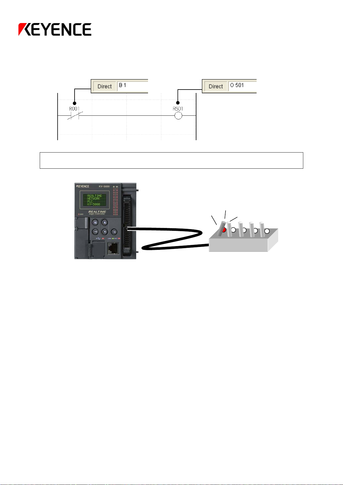
■ Example 2: a program for LDB OUT
When the switch R001 is OFF, R501 will be ON.
After the program is entered,
please transfer the program and verify its operation.
★☆★☆★☆★☆★☆★☆★☆★☆★☆★☆★☆★☆★☆★☆★☆★☆★☆★
"B_0" is the short form for "LDB_0". "LDB" stands for "LOAD
BAR", and has the same meaning as b-contact (normally closed
contact).
Attention
☆★☆★☆★☆★☆★☆★☆★☆★☆★☆★☆★☆★☆★☆★☆★☆★☆★☆
!
_ refers to a space. It is actually blank.
- 17 -
Page 19

[Writing Ladder Programs (③ AND circuit)]
If a circuit is ON when both contacts are ON, then it is called an "AND" circuit.
Please write a ladder program and verify its operation.
Add a ladder program after operation of line insertion has been performed.
■ Example 3: a program of an AND circuit (AND command)
When both the switch R002 and R003 are ON, the light R502 will be ON.
■ Example 4: a program of an AND circuit (ANB command)
When the switch R004 is ON and the switch R005 is OFF, the light R503 will be ON.
After the program is entered,
please transfer the program and verify its operation.
Processed as "AND_3" in the program.
The same result will appear even if you
have input "AND_3" or "LD_3".
Processed as "ANB_5" in the program.
The same result will appear even if you
have input "ANB_5" or "LDB_5".
- 18 -
Page 20

[Writing Ladder Programs (④ OR circuit)]
If a circuit will be ON when one of the two contacts is ON, it is called an "OR" circuit.
Please write a ladder program and verify its operation.
After deleting the program that has been written up to now through the line
deletion operation, rewrite the ladder program.
■ Example 5: a program of an OR circuit (OR command)
When either switch R000 or switch R001 is ON, the light R500 will be ON.
Processed as "OR_1" in the program.
After "OR_1" is input, the vertical line will be drawn at
the same time.
・The vertical connection line is input
through the F8 key.
・ The vertical connection line is
deleted through the Shift + F8
key.
■ Example 6: a program of an OR circuit (ORB command)
When the switch R002 is ON or the switch R003 is OFF, the light R501 will be ON.
・The vertical connection line is input
through the F8 key.
・ The vertical connection line is
deleted through the Shift + F8
key.
Processed as "ORB_1" in the program.
After "ORB_1" is input, the vertical line will be drawn at the
same time.
After the program is entered,
please transfer the program and verify its operation.
- 19 -
Page 21

[Writing Ladder Programs (Self⑤ -hold circuit)]
If the output of a circuit will be ON continuously once the contact is ON, this circuit is
called a self-hold circuit.
Please write a ladder program and verify its operation.
After deleting the program that has been written up to now through the line
deletion operation, rewrite the ladder program.
■ Example 7: a program of a self-hold circuit
When the switch R000 is ON, the light R500 will be ON.
Even if the switch R000 is OFF, the light R500 will remain ON.
When the switch R001 is ON, the light R500 will be OFF.
★☆★☆★☆★☆★☆★☆★☆★☆★☆★☆★☆★☆★☆★☆★☆★☆★☆★
Such a circuit as the above one is called a self-hold circuit.
The program flow: at the moment when the input R000 is ON, the
output R500 will be ON, and the second contact R500 will also be ON.
Since the R500 itself is ON, so it will keep its own output at the ON
state (hold), even if the input R000 is OFF.
This is a basic circuit that is effective for control when input time is
short (single pulse).
Attention
!
The self-hold circuit must contain a reset input.
(In this example, input R001 is the reset input.)
POINT The commands that have the same functions include KEEP
and SET/RES commands, etc.
Please verify them in the KV-5000/3000 Command Manual.
☆★☆★☆★☆★☆★☆★☆★☆★☆★☆★☆★☆★☆★☆★☆★☆★☆★☆
The coil and contact
are ON at the same
time
- 20 -
Page 22

[Relationship between Control and Time]
Often, time has to be considered when performing controlling devices.
The function of adjusting time through control is called "Timer" function.
Example
① Verify a signal input error, and make buzzer sound after 1 second.
② Verify that a work-piece has arrived, and set the cylinder to ON after 1
second.
③ After the conveyor belt has verified passing of the workpiece, it will still
move for a certain time.
[Timers of the KV-5000/3000]
The processing of timers is an important element of control. Of course, PLCs
represented by the KV-5000/3000 are also equipped with timers. It is possible to
realize time control only with the KV-5000/3000.
The timer commands of the KV-5000/3000 are divided into the following 3 types.
Command Symbol Mnemonics Function
#dddd
#dddd
XXX
#dddd
XXX
TMR
TMH
TMS
Timer
High speed
timer
High speed 1ms
timer
Timer number and settings
XXX : Number of timers. PLCs represented by the KV-5000/3000 equipped with
many timers.
To distinguish between various timers, we add a number to each timer in order
to facilitate management.
The number of timers that can be used depends upon the PLC model.
KV-5000/3000 may use 4000 counts between T0000-T3999.
ddddd : The time before the timer becomes ON (setting).
The setting range of this value of the KV-5000/3000 is #0-#4294967295.
Possible timing range:
Timer (TMR): 0-429496729.5 s (4971 days)
High speed timer (TMH): 0-42949672.95 s (497 days)
High speed 1ms timer (TMS): 0-4294967.295 s (49 days)
★☆★☆★☆★☆★☆★☆★☆★☆★☆★☆★☆★☆★☆★☆★☆★☆★☆★
In addition, KV-5000/3000 also has a built-in calendar timer.
Through this calendar timer, it is possible to realize control based on
"Year/Month/Day/Hour/Minute/Second/Week" system.
☆★☆★☆★☆★☆★☆★☆★☆★☆★☆★☆★☆★☆★☆★☆★☆★☆★☆
Decrement delay in 0.1 s
unit
ON timer
Decrement delay in 0.01
s unit
ON timer
Decrement delay in
0.001 s unit
ON timer
- 21 -
Page 23

[Control Based Upon ON Delay Timer]
In the following section, we will describe the controls in which timers are used.
On Delay Timer
To perform ON delay
Example: to analyze an output error.
× Without a timer ◎ Wi th a timer
Buzzer sounds instantly
When there is no timer, or the error signal vibrates, the buzzer will sound for a short period.
When there is a timer, the buzzer will sound only after an error signal is actually detected to
prevent mis-operation.
Please write a ladder program and verify its operation.
After deleting the program that has been written up to now through the line
deletion operation, rewrite the ladder program.
■ Example 8: a program of an ON delay timer
When the switch R000 is ON, the light R500 will be ON after 3 seconds.
When the switch R000 is OFF, the light R500 will be OFF immediately.
please transfer the program and verify its operation.
・・・・The timer that makes the next operation (action) delay to ON.
Error signal ON
Error signal ON
Error lasts 1 s
Buzzer sounds
After the program is entered,
- 22 -
Page 24

[Application of the ON Delay Timer]
In this section, we will discuss the controls in which the timer functions of
KV-5000/3000 are flexibly used.
First, let us consider a control combined with an ON delay timer and a self-hold
function.
For example, let's try to analyze the operation of a conveyor belt.
Please write a ladder program and verify its operation.
After deleting the program that has been written up to now through the line deletion
operation, rewrite the ladder program.
■ Example 9: a program combined with an ON delay timer and a self-hold circuit
Start switch
On delay timer
Conveyor belt starts moving
Stop switch
Conveyor belt stops moving
① After the start switch R000 is ON
Wait 3 seconds (ON delay)
②
When the timer is ON, the output R500 of
③
KV-5000/3000 will be ON and self hold.
④ After the stop switch R001 is ON
The output R500 of KV-5000/3000 is OFF
⑤
After the program is entered,
please transfer the program and verify its operation.
- 23 -
Page 25

[Control Based Upon OFF Delay Timer]
Off Delay Timer
For example, let's try to analyze the operation of a conveyor belt.
Photoelectric switch ON
Conveyor belt starts moving
Photoelectric switch OFF
Timer OFF delay
Please write a ladder program and verify its operation.
After deleting the program that has been written up to now through the line deletion
operation, rewrite the ladder program.
■ Example 10: a program of an OFF delay timer
please transfer the program and verify its operation.
a timer that enables a signal in ON state to perform OFF delay.
① After the photoelectric switch detects a workpiece
② Output of the KV-5000/3000 is ON
The conveyor belt will continue to move for some
③
time even if the work-piece has passed the sensor
completely
④ 3 seconds after the detection signal is OFF
Stop moving
Output of the KV-5000/3000 is OFF
⑤
After the program is entered,
- 24 -
Page 26

[Control Based Upon a One-Shot Timer]
One-Shot Timer
For example, let's try to analyze the operation of a buzzer.
Push button ON
■ Example 11: a program of a one-shot timer
After the program is entered, please transfer the program and verify its
A timer that generates a signal that will be ON for a certain time.
① Operator sets the push button switch R000 to
After 1 second, the output will be OFF
Buzzer sounds
Single shot timer
Buzzer stops
ON state
② Output R500 of KV-5000/3000 turns ON
immediately
③ The buzzer will sound continuously for 1
second even if the switch is OFF
④
operation.
- 25 -
Page 27

[Summary of Control Based Timers]
Do you understand control based timers?
The program charts of timers used as control centers are summed up below, so
be sure to remember them. They can help reduce the time required to write
programs.
In addition, an operation timing sequence is listed on the right of the ladder for easy
understanding. Please verify the actual operation according to the timing sequence.
ON delay timer
When switch R000 is ON, light
R500 will be ON after 3 seconds.
Output R500 will not be ON within 3
seconds after input R000 is ON.
ON
R000
OFF
ON
R500
OFF
OFF delay timer
Single-shot
When input R000 is ON, output R500
will be ON.
After R000 is OFF, R500 will be
OFF after 3 seconds.
ON
R000
OFF
ON
R500
OFF
After R000 is ON, output R500 will
be ON, and will be OFF after 3
seconds.
ON
R000
OFF
ON
R500
OFF
3 s 0.5 s
3 s
3 s 3 s
- 26 -
Page 28

[Flexible Use of Counters]
The KV-5000/3000 PLCs can perform counting.
The device that is used to count during control is called a counter.
Let’s analyze the controls in which a counter is used.
Example
① Counting of production quantity
② Counting of the quantity of defective products
[Counters of the KV-5000/3000]
Counters play an important role in control. Of course, PLCs represented by the
KV-5000/3000 are also equipped with counters. It is possible to realize counting
control only with the KV-5000/3000.
The counting commands of the KV-5000/3000 are shown as follows.
Command Symbol Mnemonics Function
#dddd
Counter
XXX
C
nnnnn
#dddd
OUT Counter
XXX
OUTC
Counter number and settings
XXX : Number of the counter. PLCs represented by the KV-5000/3000 equipped with
many counters.
To distinguish between various counters, we add a number to each counter to
facilitate management.
The number of counters that can be used depends upon the PLC model.
KV-5000/3000 may use 4000 counts between C0-C3999.
ddddd : The value until the counter is ON (setting).
The setting range of this value of the KV-5000/3000 is #0-#4294967295.
nnnnn : The number of the contact used to perform counting input.
Specifies the input relay for which the value of connected switch is to be
counted.
★☆★☆★☆★☆★☆★☆★☆★☆★☆★☆★☆★☆★☆★☆★☆★☆★☆★
Whereas timer command is always decrement operation, counter
command is always increment operation.
The reason is that a counter needs to realize overflow counting (i.e., it
will continue to count even if the setting value is reached).
☆★☆★☆★☆★☆★☆★☆★☆★☆★☆★☆★☆★☆★☆★☆★☆★☆★☆
Up counter
※
Counts according to
nnnnn, and resets when
the execution condition
is OFF.
Up counter
※
Counts according to the
execution condition, and
resets through the RES
command.
- 27 -
Page 29

[Control of Counters]
Let’s write a control program that uses a counter.
For example, let's try to analyze the management of production quantity.
The finished products will be checked using a photoelectric sensor and will be counted
using a counter of the KV-5000/3000.
A light will light up when the number of products reaches 10, notifying the operator that
production is finished.
After verifying, the operator will press the push button switch to turn off the light, and
reset the counter of the KV-5000/3000 (return to 0).
■ Timing sequence
R000
(Count)
R001
(Reset)
Setting 10
C0
(Current value)
C0
(Contact)
R500
(Output)
KV-5000/3000
(Reset)
(Output)
- 28 -
Page 30

Please write a ladder program and verify its operation.
After deleting the program that has been written up to now through the line deletion
operation, rewrite the ladder program.
■ Example 12: a program of counter
The contact is ON, the counter will reset.
Setting value of
the counter
After the current value of
the counter changes to
10, contact C0 will be
ON.
Counting input
After the program is entered,
please transfer the program and verify its operation.
★☆★☆★☆★☆★☆★☆★☆★☆★☆★☆★☆★☆★☆★☆★☆★☆★☆★
Write input conditions through the B-contact before the counter
command.
(It is LDB_1 in the above ladder)
Since B-contact is used, the power of the counter will always be
ON. (When the input R0 is ON, counting will be performed all the
time)
When this contact is disconnected, the current value of the counter
will be reset (the power of the counter is turned off).
★☆★☆★☆★☆★☆★☆★☆★☆★☆★☆★☆★☆★☆★☆★☆★☆★☆★
- 29 -
Page 31

The concepts of scan time and dual coil that are familiar to us will be described
here.
[Concept of scan time]
The KV-5000/3000 PLCs can complete operations of the entered program through
repeatedly performing a sequence of operation called "scan execution".
As shown below, scan execution is composed of three elements: input processing,
program execution processing and output processing, and the time required for "scan
execution" is called "scan time".
Input
processing
The ON/OFF state of the input will be loaded during input processing; during output
processing, the results of the program execution will be output collectively.
★☆★ The PLC with shorter scan time can write a program for a device that can
perform tasks faster ★☆★
Program execution processing
Scan time
Output
processing
[Concept of a dual coil]
Here, we describe the "dual coil" concept that has to be considered when writing a ladder
program.
The way in which the KV-5000/3000 executes a program is line by line from top to bottom
(from left to right).
PLC-specific rules apply for the steps of executing a program.
Please write a ladder program and verify its operation.
After deleting the program that has been written up to now through the line deletion
operation, rewrite the ladder program.
■ Example 13: a program of a dual coil
After the above ladder program is executed, the output R500 will not be ON even if the
contact R000 or R001 is ON. Only when R002 is ON, will R500 be ON.
After the program is entered,
please transfer the program and verify its operation.
Output R500 is used
many times.
- 30 -
Page 32

[Principle of a Dual Coil]
Here we describe the reason why execution of the verified program will cause the
operations shown in Example 13.
A ladder program will not output a result after each command execution.
★ Incorrect
・・・・①
・・・・②
・・・・③
・・・・④
R500:ON R500:ON R500:OFF
☆ Correct (refresh method)
R500:ON R500:ON R500:OFF
As described above, the PLC will not output a result after each
command execution, instead it will output total results at the end of
the scan time. Obviously, to easier for a PLC with shorter scan time
to realize high speed control.
① ②
output output output
①
② ③
③
output
④
- 31 -
Page 33

[Questions Summary]
Please consider the following issues after you have learned about circuits from this
tutorial.
Normal controls as shown below can be realized by combining the basic circuits
together.
■ Question
You are a responsible person for Production Technique in a food processing company.
In order to produce and sell new products for Christmas, it is necessary to rebuild the
production equipment.
Please try to write a program for realizing the following operation.
Example ①: Whether the produced chocolate products are good or defective needs
to be decided. After being detected by the decision sensor (R000), defective
products are to be pushed out using a 3-second push lever (R500).
Example ②:Good chocolate products are transferred on the conveyor belt.
After 12 products are detected by the sensor (R001), the buzzer (R501) will
sound for 5 seconds.
(The counter will be reset automatically after counting is finished.)
Example ③: 12 chocolates are put in one box.
The number of boxes is counted through a sensor (R002); the job
completion light will turn ON when 10 boxes are reached.
The job completion light will remain in an ON state, until operator A presses
the confirmation switch (R004).
- 32 -
Page 34

t
[Answers to Questions]
Example ①
☆ The key point is to use a single-shot timer.
Example ②
NG signal inpu
Push lever
☆ The key point is to perform a counter reset when the buzzer begins to sound
Reset signal
Counter
Self-hold circuit
Will be ON when setting of the counter is reached
It also seems possible to perform a counter reset through the buzzer
output R501; however, if the buzzer output R501 is used, the subsequent
workpieces cannot be counted, since the reset operation will be
performed all the time while the buzzer is sounding (5 seconds).
Therefore, the correct answer is that you should perform counter reset
through the signal that is output when the counter reaches its setting
value (C0).
3-second timer
5-second timer
Push lever
3-second timer
Setting
Sensor input
Counter
Self-hold circuit
5-second timer
- 33 -
Page 35

Example ③
☆ The key point is to build a self-hold circuit through the signal of the counter.
Counter
Job completion
indicator light
Self-hold circuit
Will be ON when setting of Self-hold circuit reset
the counter is reached
Counter reset is done still by the signal of C1.
When composing a self-hold circuit, don't forget the reset signal!
★☆★☆★☆★☆★☆★☆★☆★☆★☆★☆★☆★☆★☆★☆★☆★☆★☆★
The commands that have the same functions as in the self-hold circuit
include KEEP and SET/RES commands, etc.
Please verify using the following reference ladder diagrams.
Please refer to Chapter 2 "Basic Commands" in the
KV-5000/3000/1000 Command Manual.
★☆★☆★☆★☆★☆★☆★☆★☆★☆★☆★☆★☆★☆★☆★☆★☆★☆★
※SET/RES command ※KEEP command
Setting
Sensor input
- 34 -
Page 36

[Convenient Commands]
In order to make composing ladder diagrams easier, the KV-5000/3000 Series
PLCs are equipped with many convenient commands. Here we will describe
some of the commands.
Be sure to use them flexibly in subsequent programming.
The circuits described in this tutorial are frequently used circuits when building any control
schemes.
The KV-5000/3000 PLCs have added the most frequently used common circuits that
can be used for the ON delay or OFF delay ladder programs as new commands.
A circuit with multiple lines is changed into one command through new commands
(convenient commands), which reduces the time required for programming and
realizes efficient program operation.
Example ① The ON delay timer circuit
The ON delay timer circuit we discussed on the last page is shown as follows.
The two-line program can be realized using one line in a convenient command.
★☆★☆★☆★☆★☆★☆★☆★☆★☆★☆★☆★☆★☆★☆★☆★☆★☆★
A convenient command also has advantages/disadvantages.
The advantages are: the program is simplified, time for
programming is reduced, and scan time is shorter. In addition, it
can be used without limit, since no timer number is required.
The disadvantages are: the timer unit is only 0.01 s, and the current value
cannot be displayed during monitoring, etc. (The normal timer can monitor
the decrement state.)
Please use normal commands and convenient commands flexibly
according to different conditions.
★☆★☆★☆★☆★☆★☆★☆★☆★☆★☆★☆★☆★☆★☆★☆★☆★☆★
NOTE The unit of the timer is 0.01s.
Therefore, a setting value of 3 s should be
entered by #300.
- 35 -
Page 37

Example ② The OFF delay timer circuit
The ON delay timer circuit we discussed on last page is shown below.
The two-line program can be realized through one line in a convenient command.
The following convenient commands are included in the KV-5000/3000.
・ SET command ・ RESET command
・ ON delay command ・ OFF delay command
・ Blinking command
・ Single-shot command ・ Alternating command
★ Be sure to try to using them in the program and verify their operation!
- 36 -
Page 38

[Simulator Function]
Until now, switches and other devices have been used to verify operation after a
program is transferred to the KV-5000/3000 unit. However, when configuring a
device, the PLC unit is often connected to the device. Even if you want to
perform a program test (debugging), sometimes it is not possible to verify before
the device installation is finished.
In order to avoid this kind of debugging problem, the KV-5000/3000 is equipped with a
"simulator function" in the ladder support software "KV STUDIO", through which it is
possible to debug a program without transferring the ladder program to the unit.
Here, we will describe how to use the simulator.
■ The method used until now
■ The simulator function of the KV STUDIO
★☆★☆★☆★☆★☆★☆★☆★☆★☆★☆★☆★☆★☆★☆★☆★☆★☆★
The following page will describe how to start the simulator.
After confirmation, please practice the programs you have learned
until now (self-hold or timer/counter) by using the simulator.
In addition to having the simple timer/counter function, this simulator
function is very useful for operation programs used in the future.
Be sure to understand it.
★☆★☆★☆★☆★☆★☆★☆★☆★☆★☆★☆★☆★☆★☆★☆★☆★☆★
The ladder diagram is
transferred to the PLC,
and operations of the
program are verified.
It is possible to verify
operation of the program by
only using a PC.
- 37 -
Page 39
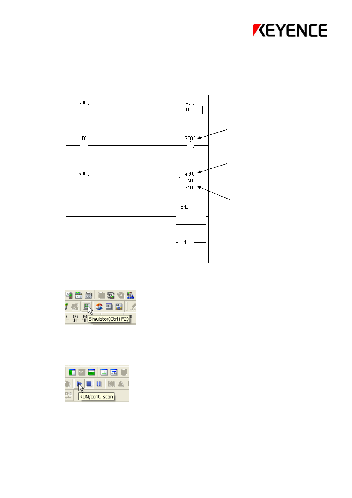
① First, write the program as shown below.
This is the program written by using the ON delay timer through a common method,
in which convenient commands are used.
After the input R000 is ON, it is possible to verify that the normal command and the
convenient command have set output R500 and R501 to ON simultaneously.
Output R500
Pay attention to the unit!
Output R501
② Click the "Simulator" icon to run the simulator.
③ Change to the simulator screen, and click the "Execute continuous scan" icon.
The ladder program will run on the PC.
- 38 -
Page 40

④ On the simulator screen, double click a contact on the ladder program to switch
the input ON/OFF。
Try to double click the input R000. The input will be ON, and the timer will
begin to operate.
Double click the cell
for the contact R000
⑤ After 3 seconds, both inputs will be ON.
⑥ On the simulator screen, double click
the contact on the ladder program again.
The input R000 will turn OFF, and the timer will reset.
- 39 -
Page 41

MEMO
- 40 -
Page 42

[End]
Were you able to understand and grasp the content in this tutorial?
If you have any questions about the content in this tutorial, please contact our
company's business office.
The personnel of each business office are ready to help you.
You are also welcome to purchase any of our products in the future.
※All of the content in this tutorial is copyrighted.
Reprinting or reproduction is not allowed without permission.
Model ※ number, specifications, and other information are subject to change without notice
- 41 -
1094-1 600F63
 Loading...