

Page 1

96M12231
Intelligent monitor
IV-M30
Instruction Manual
Read this manual before using the product in order to
achieve maximum performance.
Keep this manual in a safe place after reading it so that it
can be used at any time.
For details of functions, refer to the IV Series User's Manual
(Monitor).
The IV Series User's Manual can be downloaded from the
KEYENCE web site:
http://www.keyence.com/
Symbols
The following symbols alert you to important messages.
Be sure to read these messages carefully.
It indicates a hazardous situation which, if not
avoided, will result in death or serious injury.
It indicates a hazardous situation which, if
not avoided, could result in death or serious
injury.
It indicates a hazardous situation which, if not
avoided, could result in minor or moderate
injury.
It indicates a situation which, if not avoided,
could result in product damage as well as
property damage.
It indicates cautions and limitations that must
be followed during operation.
It indicates additional information on proper
operation.
It indicates tips for better understanding or useful
information.
Cautions
(1) Unauthorized reproduction of this manual in whole or
part is prohibited.
(2) The contents of this manual may be changed for
improvements without prior notice.
(3)
An utmost effort has been made to ensure the contents of
this manual are as complete as possible. If there are any
mistakes or questions, please contact a KEYENCE ofce
listed in the back of the manual.
(4) Regardless of item (3), KEYENCE will not be liable for
any effect resulting from the use of this unit.
(5) Any manuals with missing pages or other paging faults
will be replaced.
The company names and product names used in this
manual are registered trademarks or the trademarks of their
respective companies.
You must verify that the IV Series are operating
correctly in terms of functionality and performance
before the start and the operation of the IV
We recommend that you take substantial
safety measures to avoid any damage in the
event of a problem occurring.
KEYENCE never warrants the function or performance
of the IV-M30 if it is used in manner that differs from
the IV-M30 specications contained in this instruction
manual or if the IV-M30s are modied by yourself.
When the IV-M30 is used in combination with
other instruments, functions and performance
may be degraded, depending on operating
conditions and the surrounding environment.
Do not place the instruments, including
peripherals, under rapid temperature
change. It may cause condensation and may
damage instruments or peripherals.
Remove the power cable from the power supply
if you do not use IV-M30 for a long time.
Series.
Important Instructions
Observe the following precautions to prevent malfunction of
the IV Series and to ensure that it is used properly.
Precautions on use
The power of the IV-M30 and instruments
connected to IV-M30 must be turned off when the
cable is to be installed or removed. Failure to do so
may cause an electric shock or a product damage.
Use the IV-M30 in the correct supply voltage.
Failure to do so may cause product damage.
For instructions
Do not turn OFF the power while setting
the items or saving the settings. Otherwise,
all or part of the setting data may be lost.
The enclosure rating of the monitor (IV-M30)
is IP40. As it is not waterproof, be careful
when handling it.
When the IV-M30 becomes dirty, do not rub it with
a wet cloth, benzene, thinner, or alcohol. Doing
so may change the color or shape of the unit.
If the unit is heavily contaminated, disconnect
all the cables including the power supply cable,
wipe off the dirt with a cloth soaked with mild
detergent, and then wipe with a soft dry cloth.
LCD panel
Do not press the touch panel with the tip of your
nail or anything that has a sharp tip such as a pen
or a screwdriver. Doing so may cause damage.
Do not apply shock to the touch panel or press it
with excessive force. Doing so may cause damage.
The LCD panel may have some dots that are always
lit (bright dots) or ones that are always unlit (black
dots). This phenomenon is not a problem.
Due to the unique characteristics of an
LCD, displaying the same image for a long
time may cause an afterimage.
USB memory
Use products recommended by KEYENCE.
A USB memory device with a security
function cannot be used.
Unplug the USB memory when turning on
or off the power of IV-M30.
Do not remove the USB memory while the USB
is being written on. Otherwise, all or part of the
setting data may be lost or it may cause damage.
Safety Information for IV-M30
General Precautions
Do not use this product for the purpose to
protect a human body or a part of human body.
This product is not intended for use as an explosion-
proof product. Do not use this product in a hazardous
location and/or potentially explosive atmosphere.
Measures to be taken when an abnormality occurs
In the following cases, turn the power OFF
immediately. Using the IV Series in an abnormal
condition could cause re, electric shock, or
malfunction. Contact our ofce for repair.
If water or debris enters the IV Series.
If the IV Series is dropped or the case is damaged.
If abnormal smoke or odor emanates from
the IV Series.
1
IV Series (Monitor) - IM_E
Page 2

Precautions on installation
To use the IV-M30 correctly and safely, avoid
installing it in the following locations. Failure
to do so may cause re, electric shock, or
malfunction.
Outdoors
Altitude above 2000 m
Locations that are humid, dusty or poorly
ventilated
Locations where the temperature is high
such as those exposed to direct sunlight
Locations where there are ammable or
corrosive gases
Locations where the unit may be directly
subjected to vibration or impact
Locations where water, oil, or chemicals
may splash onto the unit
To improve the anti-noise feature, install
the unit following the precautions below.
Otherwise, a malfunction may occur.
Do not mount the unit in a cabinet where
high-voltage equipment is already installed.
Mount the unit as far from power lines as
possible.
Separate the unit as far as possible from the
devices that emit strong electric or magnetic
eld (such as solenoid or chopper).
Separate the I/O signal line from the power
line or high-voltage line.
For power supply
Noise superimposed on the power supply
could cause malfunction. Use a stabilized
DC power supply congured with an
isolation transformer.
When using a commercially available
switching regulator, be sure to ground the
frame ground terminal.
Devices including this unit are precision
components. Do not apply shock or vibration.
When connecting to a network, let engineers
who are knowledgeable about networks
handle it.
Precautions on Regulations and Standards
UL Certication
This product is a UL/C-UL Listed product.
UL File No. E207185
Category NRAQ, NRAQ7
Be sure to consider the following specications when using
this product as a UL Listed product
Use a power supply with Class 2 output dened in
NFPA70 (NEC: National Electrical Code).
This product is for use on a at surface of a Type 1 enclosure.
Checking the Package Contents
Intelligent Monitor
IV-M30
Stylus x 1
String for hanging the stylus x 1
Monitor x 1
Instruction Manual x 1
(This manual)
Starting Guide x 1
Wall mounting adapter x 1
Screw for adapter x 2
Hexagon nut x 2
Options for Monitor
Monitor power cable (M8 4pin - strand wire)
OP-87443 (2m) OP-87444 (5m) OP-87445 (10m)
Monitor power cable (M8 4pin - strand wire) x 1
USB memory (1GB)
OP-87502
USB memory x 1
Protection sheet
OP-87463
CE Marking
Keyence Corporation has conrmed that this product complies with
the essential requirements of the applicable EC Directive, based
on the following specications. Be sure to consider the following
specications when using this product in the Member State of
European Union.
EMC Directive (2004/108/EC)
Applicable Standard EMI : EN61326-1, Class A
EMS : EN61326-1
The length of Monitor power cable, Ethernet cable and
Monitor cable must be less than or equal to 30m.
Remarks:
These specications do not give any guarantee that the
end-product with this product incorporated complies
with the essential requirements of EMC Directive. The
manufacturer of the end-product is solely responsible
for the compliance on the end-product itself according to
EMC Directive.
IV Series (Monitor) - IM_E
Protection sheet x 1
Stylus
OP-87462
String for hanging the stylus x 1
Stylus x 1
Same as accessories for monitors.
Optional parts in case of loss/damage.
2
Page 3
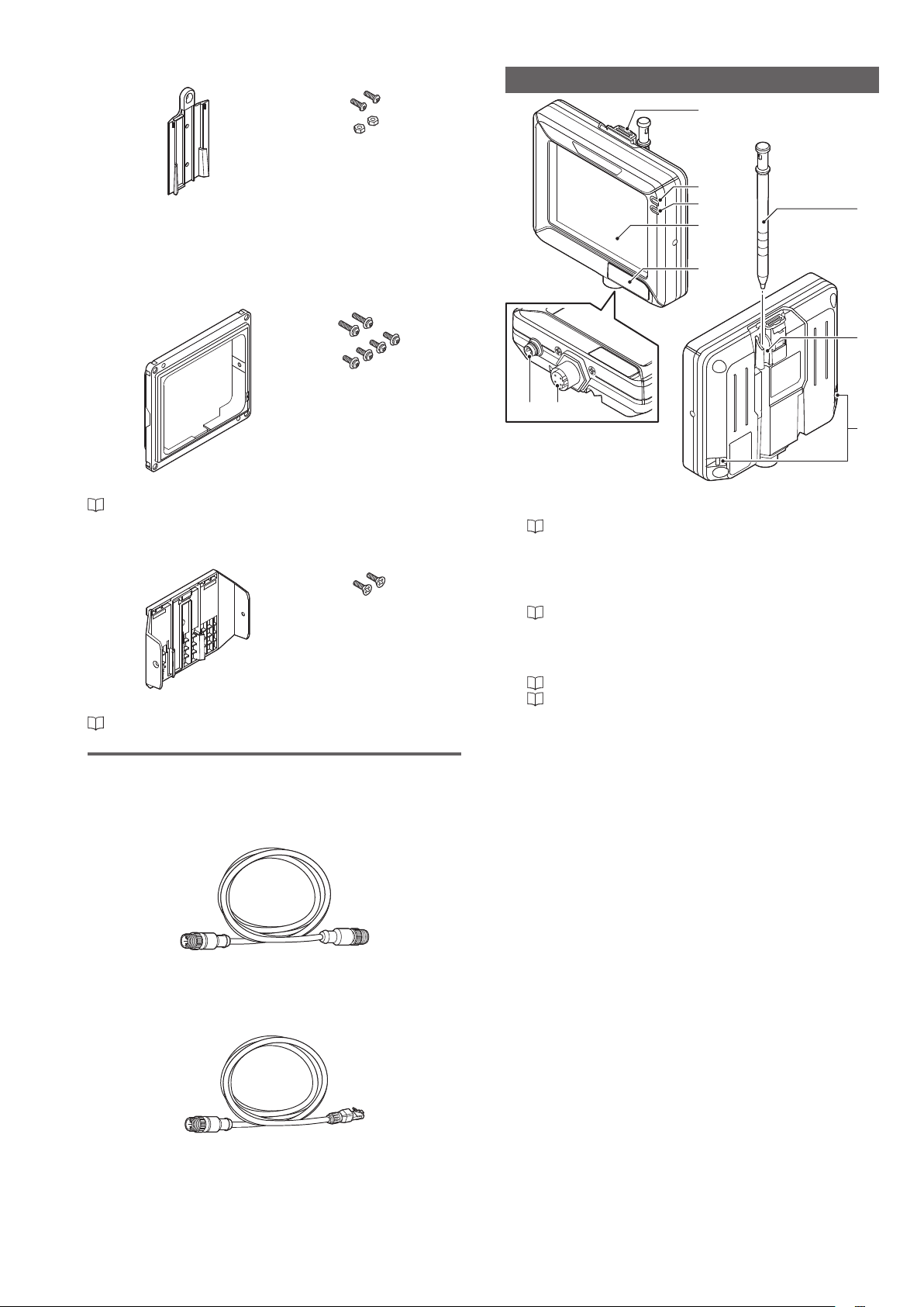
Wall mounting adapter
10
OP-87464
Screws for adapter x2
Hexagon nut x 2
Wall mounting adapter x 1
Same as accessories for monitors.
Optional parts in case of loss/damage.
Panel mounting adapter
OP-87465
Mounting screw
(lateral) x 2
Mounting screw
(front) x 4
Name and function of each part
3
4
5
6
7
21
8
9
Panel mounting adapter x 1
“Mounting to a panel” (Page 5)
DIN mounting adapter
OP-87466
Mounting screw
(lateral) x 2
DIN mounting adapter x 1
“Mounting to the DIN rail” (Page 5)
Communication Cable
Monitor cable (M12 4pin - M12 4pin)
OP-87450 (2m)
OP-87451 (5m)
OP-87452 (10m)
OP-87453 (20m)
1 Power connector
Connects the monitor power cable.
“Cables” (Page 6)
2 Connector for the mo
Connector for connecting the monitor cable or Ethernet
cable. Used when connecting with the sensor or Ethernet
switch.
“Cables” (Page 6)
3 Unlock button
Push this button when dismounting the monitor from the
wall mounting adapter or DIN mounting adapter.
“Unmounting from the wall mounting adapter” (Page 5)
“Unmounting from the DIN mounting adapter” (Page 6)
4 Indicator light (PWR)
Indicates the operating status of the monitor.
Green (ON) ...... The power is turned ON.
Red (ON) .......... Unrecoverable error occurred to the
Red (Blink) ....... Recoverable error occurred to the
(OFF) ............... The power is turned OFF.
nitor cable/Ethernet cable
sensor or monitor.
sensor or monitor.
Monitor cable (M12 4pin - M12 4pin) x 1
Ethernet cable (M12 4pin - RJ-45)
OP-87457 (2m) OP-87458 (5m) OP-87459 (10m)
Ethernet cable (M12 4pin - RJ-45) x 1
3
IV Series (Monitor) - IM_E
Page 4

5 Indicator light (SENSOR)
Indicates the connecting status to the sensor.
Green (ON) ...... Connected normally to the sensor.
Green
(Slowly blinks)
(OFF) ............... It is not properly connected because it
6 LCD monitor/Touch panel
Displays the operation screen and setup screen.
Operates by touching the screen with the stylus.
7 USB connecting connector
Connector for connecting the USB memory. Connector is
protected by a cover.
8 Stylus
Used to operate the touch-screen.
9 Stylus holder
Stores the stylus.
10
Strap holder
Holds the strap or hangs the stylus.
... Linked normally but it is not properly
connected to the sensor.
did not link normally.
Attachment
Mounting to a wall
Use the wall mounting adapter (accessories or OP-87464).
Hang it on the hook with the wall mounting adapter mounted
to the monitor, or mount the monitor to the wall mounting
adapter mounted on the wall.
The monitor is shipped with the wall mounting
adapter mounted.
Hanging on the hook
For operation take the monitor from the hook and operate it
while holding it in your hands.
Mount the monitor to the wall mounting adapter
1
by aligning the stopper of the wall mounting
adapter to the groove on the rear monitor.
Slide the monitor down all the way, and conrm that the
monitor is locked.
Hang the monitor on the hook.
2
Mounting with the wall mounting adapter
The monitor can be operated by the following methods.
Unhang to pick up the monitor from the hook and operate it.
Operate it while mounted on the wall.
Mount the wall mounting adapter to the wall.
1
Mounting by creating a screw hole in the wall
Screw : M3 x 2
Use commercially available screws.
Tightening torque : 0.27 to 0.33 N·m
Mounting by creating a plated through hole on the
panel
Screw : M3 x 2, Nut : M3 x 2
Use the attached screws and nuts.
Tightening torque : 0.27 to 0.33 N·m
IV Series (Monitor) - IM_E
Stopper
Mount the monitor to the wall mounting adapter
2
by aligning the stopper of the wall mounting
adapter to the groove on the rear monitor.
Slide the monitor down all the way, and conrm that the
monitor is locked.
Stopper
4
Page 5

Unmounting from the wall mounting adapter
Unlock the monitor from the wall mounting adapter by pulling
toward the unlock button. And slide up to unmount the
monitor mounted to the adapter.
Unlock
Mount the monitor with the panel adapter
3
mounted to the control board from the rear side,
and x it with the screws.
Make a “92mm x 111mm” size mounting hole on the
control board.
Mountable board thickness : 1 to 4 mm
Screw : M3, 7 mm long, with 4 washers
Use the attached screws.
Tightening torque : 0.5 N·m or lower
Mounting to a panel
Operate the monitor by mounting it to a panel such as a
control board.
Mount the panel adapter (OP-87465) to the monitor, and
mount it to the panel.
Connect the power cable and monitor cable to the
1
monitor.
“Cables” (Page 6)
Mount the panel adapter to the monitor and x it
2
with the attached screws.
Screw : M3, 11 mm long, with 2 washers
Use the attached screws.
Tightening torque : 0.27 to 0.33 N·m
Strap holder
Stylus can be hung from the strap holder
using the hanging string (accessory).
Mounting to the DIN rail
Mount the DIN adapter (OP-87466) to the monitor, and
mount it to the DIN rail.
The monitor can be operated by the following methods.
Pick up the monitor from the DIN mounting adapter and
operate it.
Operate it while mounted on the DIN rail.
Mounting using DIN mounting adapter
Mount the monitor to the DIN mounting adapter.
1
Slide the monitor until the end of the stopper, and conrm
that the monitor is locked.
Stopper
Fixing to the DIN mounting adapter
To x the monitor to the DIN mounting adapter, use the
attached screws.
Screw : M3 x 2
Use the attached at head screw.
Tightening torque : 0.27 to 0.33N·m
5
IV Series (Monitor) - IM_E
Page 6

Adjust the position of the DIN mounting adapter
2
and the DIN rail by pulling down the stopper of the
adapter, and then push up the stopper to lock it.
Stopper
Unmounting from the DIN mounting adapter
Unlock the monitor from the DIN mounting adapter by pulling
toward the unlock button. And slide up to unmount the
monitor mounted to the adapter.
Wire to the power supply.
3
Monitor power cable
(2m/5m/10m)
Cable specication Brown/Blue: AWG24
Brown (DC24V)
Blue (0V)
DC24V
Unlock
Cables
Connecting the power cable of the monitor
Align the arrow mark of the power cable and the
1
direction of the front monitor, and connect the
cable to the monitor.
Connecting the sensor and the monitor
Connecting directly
Connect the sensor and monitor using the monitor cable.
Monitor cable
(2m/5m/10m/20m)
For details on connecting the monitor cable, refer to
“Connecting the monitor cable/Ethernet cable” (Page 7).
Arrow mark
Turn the screw-on connector in clockwise direction
2
to tighten it.
IV Series (Monitor) - IM_E
6
Page 7

Connecting via network
Connect each Ethernet cable to the monitor and sensor.
Connect the other side of the Ethernet cable to the Ethernet
switch.
Ethernet switch
Ethernet cable
(2m/5m/10m)
For details on connecting the Ethernet cable, refer to
“Connecting the monitor cable/Ethernet cable” (Page 7).
The sensor and monitor do not support PoE
(Power over Ethernet). Supply power using
the power cable.
Connecting the monitor cable/Ethernet cable
This section describes the details on connecting the monitor
cable/Ethernet cable using the example of connecting the
monitor cable to the sensor.
Align the pin connection parts of the monitor
1
cable/Ethernet cable connector with three pins of
the cable connector, and connect the cable to the
sensor.
Tighten the connector by turning the screw-
2
on connector in the clockwise direction. When
connecting the connector, insert it without
inclination while pushing in and tighten it well.
(2)
When the screw stops rotating by the locking
mechanism, further tighten it while pushing.
(1)
Tighten the screw.
* Same procedures for monitors.
Repeat the steps (1) and (2) and when you cannot
tighten the screw by hand any more, use a tool such as
pliers for further tightening. Tightening torque, retorque
degree, and acceptable spaces between connectors are
shown below.
Monitor cable/Ethernet cable
(OP-87450/OP-87451/OP-87452/OP-87453/
OP-87457/OP-87458/OP-87459)
Tightening torque : 0.8 to 1.0 N·m
Retightening degree
Spaces between connectors (reference value)
For sensors : 0 mm
For monitors : 2.2 mm
If the connector cable tightening is weak,
vibration may loosen the connector and cause
bad connections or cable disconnections.
Also, the enclosure rating may not be
maintained with loose connection.
Properly follow the procedures above and
tighten the connector completely.
Check the spaces between the monitor cable/
Ethernet cable and the cable connector.
For sensors
: 5 to 10°
Spaces between
connectors
For monitors
Align the pins and
the pin connection
* Same procedures for monitors.
Spaces between
connectors
7
IV Series (Monitor) - IM_E
Page 8

Dimensions
6
98.7
Monitor
IV-M30
1.4
52.12
84
(Display area)
(52)
R20
(109)
R50
Using the wall mounting adapter
8
2.74
102.3
70.56
(Display area)
(2.2)
(13)
USB port
26.4
(Excluding the
convexed surface)
Using the panel mounting adapter
119
110
109 100 91.5
(40)
110.5
4-M3
Screw depth 4.2
30.3
4 22.8
Panel thickness
1 to 4mm
40
20.2
2-φ3.5
Mounting hole dimension
40
+1
92
0
Panel cutting dimensions
110
2-M3
111
4-φ3.5
100
+1
0
(97)
IV Series (Monitor) - IM_E
8
Page 9

yUsing the DIN mounting adapter
107
3.7
φ9.5
47.3
47.3
φ14.8
φ14.8
35.9
57.1
33.8
Monitor power cable
OP-87443 (2m) / OP-87444 (5m) / OP-87445 (10m)
φ
26.7
2000
5000
10000
Monitor cable
OP-87450 (2m) / OP-87451 (5m) / OP-87452 (10m) / OP87453 (20m)
φ6.4
2000
5000
10000
20000
Ethernet cable
OP-87457 (2m) / OP-87458 (5m) / OP-87459 (10m)
φ6.4
2000
5000
1000047.3 59
14.6
9
IV Series (Monitor) - IM_E
Page 10

Specications
Model IV-M30
Display
Method White LED
Backlight
Duration Approx. 50,000 hours (25 ˚C)
Touch
panel
Method Analog resistive
Actuating
force
Indicators PWR, SENSOR
Standard 100BASE-TX/10BASE-T
Ethernet
*1
Connector M12 4pin connector
Languages
Expanded memory USB memory
Power
voltage
Rating
Consumption
current
Ambient
temperature
Relative
humidity
Environmental
Vibration
resistance
Drop
impact
resistance
Enclosure
rating
Material Polycarbonate
Weight Approx. 180 g
3.5" TFT color LCD
320 x 240 dot (QVGA)
0.8 N or less
Japanese / English / Deutsch /
Chinese (Simplied) /
Chinese (Traditional) / Italian /
French / Spanish / Portuguese /
Korean
DC24V ± 10% (including ripple)
0.2 A or lower
0 to + 50˚C (No freezing)
35 to 80 % RH
*3
(No condensation)
10 to 55 Hz, 0.7 mm double
amplitude, 2 hours each for X, Y,
and Z axes
1.3m over the concrete (2 times
each in the arbitrary direction)
IP40
Warranties and Disclaimers
(1) KEYENCE warrants the Products to be free of defects in materials and
workmanship for a period of one (1) year from the date of shipment. If any
models or samples were shown to Buyer, such models or samples were
used merely to illustrate the general type and quality of the Products and not
to represent that the Products would necessarily conform to said models or
samples. Any Products found to be defective must be shipped to KEYENCE
with all shipping costs paid by Buyer or offered to KEYENCE for inspection and
examination. Upon examination by KEYENCE, KEYENCE, at its sole option,
will refund the purchase price of, or repair or replace at no charge any Products
found to be defective. This warranty does not apply to any defects resulting from
any action of Buyer, including but not limited to improper installation, improper
interfacing, improper repair, unauthorized modication, misapplication and
mishandling, such as exposure to excessive current, heat, coldness, moisture,
vibration or outdoors air. Components which wear are not warranted.
(2) KEYENCE is pleased to offer suggestions on the use of its various Products.
They are only suggestions, and it is Buyer's responsibility to ascertain the
tness of the Products for Buyer’s intended use. KEYENCE will not be
responsible for any damages that may result from the use of the Products.
(3) The Products and any samples ("Products/Samples") supplied to Buyer are not
to be used internally in humans, for human transportation, as safety devices or
fail-safe systems, unless their written specications state otherwise. Should any
Products/Samples be used in such a manner or misused in any way, KEYENCE
assumes no responsibility, and additionally Buyer will indemnify KEYENCE and
hold KEYENCE harmless from any liability or damage whatsoever arising out of
any misuse of the Products/ Samples.
(4) OTHER THAN AS STATED HEREIN, THE PRODUCTS/SAMPLES ARE
PROVIDED WITH NO OTHER WARRANTIES WHATSOEVER. ALL EXPRESS,
IMPLIED, AND STATUTORY WARRANTIES, INCLUDING, WITHOUT
LIMITATION, THE WARRANTIES OF MERCHANTABILITY, FITNESS FOR A
*2
PARTICULAR PURPOSE, AND NON-INFRINGEMENT OF PROPRIETARY
RIGHTS, ARE EXPRESSLY DISCLAIMED. IN NO EVENT SHALL KEYENCE
AND ITS AFFILIATED ENTITIES BE LIABLE TO ANY PERSON OR ENTITY
FOR ANY DIRECT, INDIRECT, INCIDENTAL, PUNITIVE, SPECIAL OR
CONSEQUENTIAL DAMAGES (INCLUDING, WITHOUT LIMITATION, ANY
DAMAGES RESULTING FROM LOSS OF USE, BUSINESS INTERRUPTION,
LOSS OF INFORMATION, LOSS OR INACCURACY OF DATA, LOSS
OF PROFITS, LOSS OF SAVINGS, THE COST OF PROCUREMENT OF
SUBSTITUTED GOODS, SERVICES OR TECHNOLOGIES, OR FOR ANY
MATTER ARISING OUT OF OR IN CONNECTION WITH THE USE OR
INABILITY TO USE THE PRODUCTS, EVEN IF KEYENCE OR ONE OF ITS
AFFILIATED ENTITIES WAS ADVISED OF A POSSIBLE THIRD PARTY’S
CLAIM FOR DAMAGES OR ANY OTHER CLAIM AGAINST BUYER. In some
jurisdictions, some of the foregoing warranty disclaimers or damage limitations
may not apply.
BUYER'S TRANSFER OBLIGATIONS:
If the Products/Samples purchased by Buyer are to be resold or delivered to a
third party, Buyer must provide such third party with a copy of this document, all
specications, manuals, catalogs, leaets and written information provided to
Buyer pertaining to the Products/Samples.
E 1101-3
*1 This is dedicated for connection with IV-series sensor.
*2 Use the KEYENCE recommended product.
*3 If the ambient temperature is over 40˚C, use it in the
absolute humidity of 40˚C 80% RH or lower.
IV Series (Monitor) - IM_E
Copyright (c) 2012 KEYENCE CORPORATION. All rights reserved.
12231E 1123-2 96M12231 Printed in Japan
10
 Loading...