

Page 1
IL Series
User’s Manual
Read this manual before using in order to achieve
maximum performance.
After reading, keep this manual in a safe place so that
you can refer to it at any time.
CMOS Multi-Function
Analog Laser Sensor
236GB
Page 2
Introduction
This manual describes the basic operations and information for the IL Series.
Read this manual carefully to ensure performance and function of the IL Series for safe use.
Keep this manual in a safe place for future reference.
Make sure this manual is provided to the end user of this device.
Symbols
The following symbols alert you to important messages. Be sure to read these messages
carefully.
DANGER
WARNING
CAUTION
NOTICE
Important
Point
Reference
It indicates a hazardous situation which, if not avoided, will result in
death or serious injury.
It indicates a hazardous situation which, if not avoided, could result in
death or serious injury.
It indicates a hazardous situation which, if not avoided, could result in
minor or moderate injury.
It indicates a situation which, if not avoided, could result in product
damage as well as property damage.
It indicates cautions and limitations that must be followed during
operation.
It indicates additional information on proper operation.
It indicates tips for better understanding or useful information.
Provides reference pages.
Page 3
Safety Precautions
WARNING
General Precautions
• At startup and during operation, be sure to monitor the functions and performance of this
product and confirm normal operation.
• We recommend that you take substantial safety measures to avoid any damage in the
event that a problem occurs.
• If the product is modified or used in any way other than those described in the
specifications, its functions and performance cannot be guaranteed.
• When this product is used in combination with other devices, the functions and
performance may be weaken, depending on the operating conditions, surrounding
environment, etc.
• Do not use this product for the purpose of protecting the human body.
• Do not subject each device including peripheral devices to rapid temperature change.
Product failure may occur due to condensation.
Safety Information for the IL series
• This product is just intended to detect the object(s). Do not use
this product for the purpose to protect a human body or a part of
human body.
• This product is not intended for use as explosion-proof product.
Do not use this product in hazardous location and/or potentially
explosive atmosphere.
Safety Precautions on Laser Products
• Use of controls or adjustments or performance of procedures other than those specified
herein may result in hazardous radiation exposure.
• Follow the instructions mentioned in this manual. Otherwise, injury to the human body
(eyes and skin) may result.
• Do not disassemble this product. Laser emission from this product is not automatically
stopped when it is disassembled.
• Precautions on class 2 laser products
- Do not stare into the beam.
- Do not direct the beam at other people or into areas where other people unconnected
with the laser work might be present.
- Be careful of the path of the laser beam.
When the laser beam is reflected or diffused from a mirror surface, and this reflection
may cause danger, block this reflection using a surrounding enclosure.
- Install the products so that the path of the laser beam is not as the same height as that
of human eye.
IL-E
236GB
1
Page 4
Laser radiation
emission indicator
<Sensor amplifier>
<Sensor head>
Item Description
Model IL-030
Wavelength 655 nm 655 nm
FDA (CDRH)
Part1040.10
IEC 60825-1
Laser Class Class 1 Laser Product* Class 2 Laser Product*
Output 220 μW560 μW
Laser Class Class 1 Laser Product Class 2 Laser Product
Output 220 μW560 μW
IL-S025/IL-S065/IL-065/
IL-100/IL-300/IL-600/
IL-2000
* The classification is implemented based on IEC60825-1 following the requirement of
Laser Notice No.50 of FDA (CDRH).
Safety measures for the laser
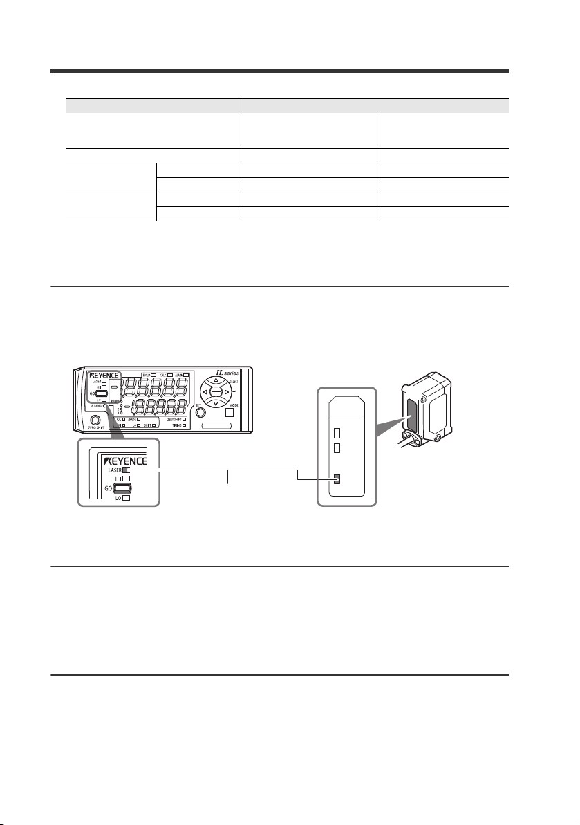
Laser radiation emission indicator
The laser radiation emission indicator is lit during laser emission. It flashes when laser
emission is stopped.
IL-030
CENTER
A. RANGE
LASER
The position of the indicator of the IL-S025/IL-S065/IL-2000 will differ from above.
Laser emission stop input
When laser emission stop input is set as an external input, laser emission can be stopped
by turning on the external input (input response time 20 ms). Laser emission remains
stopped while the external input is on. The laser is emitted within 20 ms being external
input of the turned off. For the conditions of detection outputs and analog outputs during
laser emission stop input, refer to
Warming up
Leave the IL Series about 30 minutes after turning on the power.
The circuit is not stable immediately after the power turns on, so the display value may
gradually fluctuate.
2
"11. External Input" (page 4-30) of the User's Manual.
IL-E
Page 5
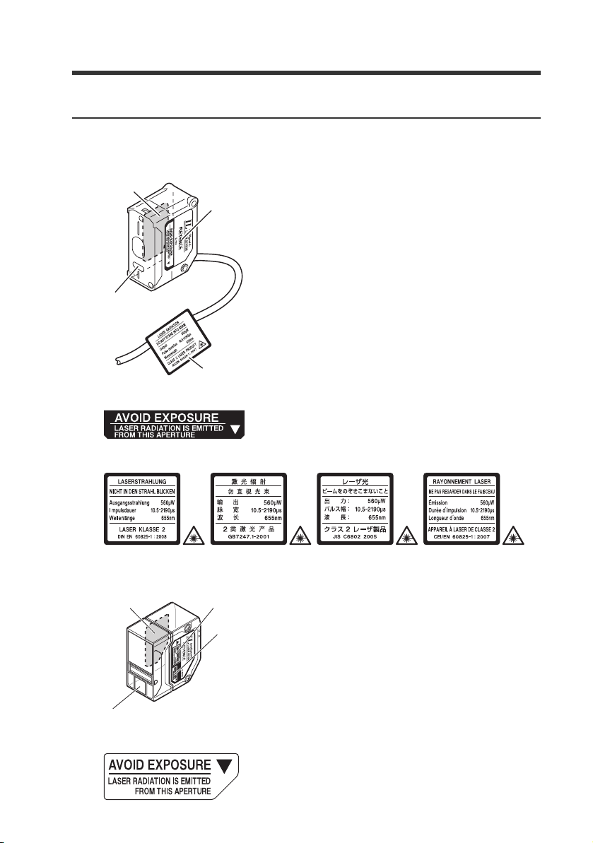
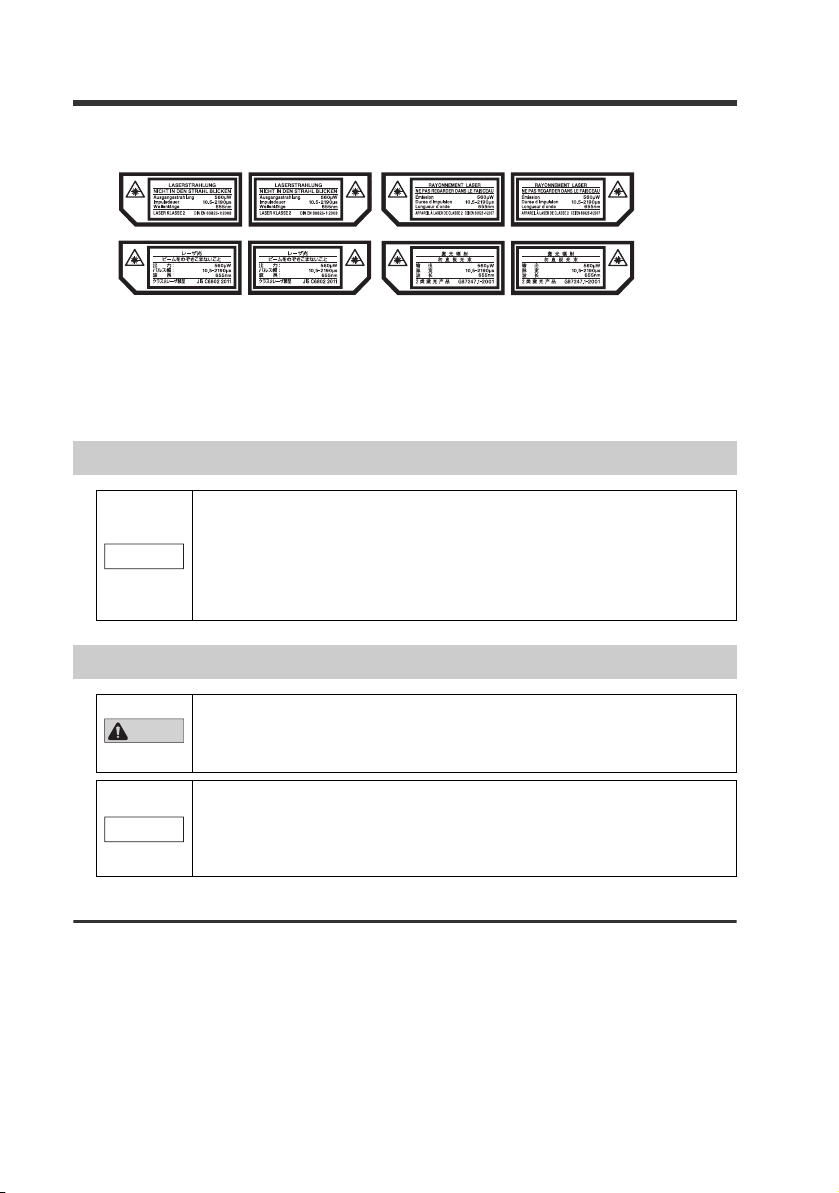
Laser warning labels
Aperture
label
Aperture
label
Laser
transmitter
IEC warning label (Class 2)
Aperture
label
Aperture
label
Laser transmitter
IEC warning/explanatory
label (Class 2)
The following diagrams show the type and position of laser warning labels on to the IL Series.
IL-S025/IL-S065/IL-065/IL-100/IL-300/IL-600
Aperture label
IEC warning/explanatory label (CLASS 2)
IL-E
IL-2000
Aperture label
3
Page 6
CAU
IEC warning/explanatory label (CLASS 2)
The IEC warning/explanatory labels are only affixed to Class 2 laser products.
Use the suitable IEC warning/explanatory label included in the package of this product
according to the countries and/or regions where this product is used.
In this case, it can be affixed on the IEC warning/explanatory label, which has already been
affixed to this product.
Abnormal Conditions
If the following conditions occur, turn OFF the power immediately.
Continuing to use this product under abnormal conditions may
NOTICE
cause product failure.
• When water or foreign matter enters the IL Series
• When the IL Series is dropped or the case is damaged
• If smoke or unpleasant odor is present.
Precautions on Use
• Use with the correct power source and voltage. Otherwise, fire,
CAUTION
NOTICE
electric shock or product failure may result.
• Do not attempt to open or modify the IL Series. Doing so may
cause fire or electric shock.
• Before disconnecting the cables, make sure to turn off the main
unit and devices connected to the main unit. Otherwise, the unit
may be damaged.
• Do not turn off the power while modifying settings. Some or all of
the setting data may be lost.
Installation environment
To use this product normally and safely, do not install this product in the following locations.
Product failure may occur.
• High-humidity, dusty and poorly-ventilated locations
• High-temperature locations where the unit is exposed to direct sunlight
• Locations where there is corrosive or combustible gas
• Locations where the unit may be directly subjected to vibration or impact
• Locations where water, oil or chemicals may splash onto the unit
• Locations where static electricity tends to be generated
4
IL-E
Page 7

Influence of dirt
Measurement errors may occur due to dust, water, oil, etc.
• Blow away dirt on the transmitter and the receiver with clean air. Wipe with a soft cloth
moistened with alcohol for heavy dirt.
• Blow away the dirt attached to the object with clean air or wipe it off.
• If dirt is floating in the measurement range, take adequate measures, such as installing a
protective cover or air purge.
Anti-noise prevention
When the unit is installed near electric noise source such as a power source or high-voltage
line, operational errors or product failure may occur. Take adequate measures such as using a
noise filter, arranging cables separately or insulating the sensor amplifier and the sensor head.
Power ON Reset
After the power is turned ON, it will take approx. two seconds for the measurement to start.
The judgment results will be output after the sampling period has elapsed.
Other Precautions
Power source
• Noise superimposed on the power supply may cause malfunction. Use a direct current
stabilized power source which uses an insulation transformer.
• When using a commercially available switching regulator, make sure to ground the frame
ground terminal.
Precautions on Regulations and Standards
CE Marking
Keyence corporation has confirmed that this product complies with the essential
requirements of the applicable EC Directives, based on the following specifications.
Be sure to consider the following specifications when using this product in the Member
States of European Union.
EMC Directive
• Applicable standards EMI : EN61326-1,ClassA
EMS : EN61326-1
• The length of the sensor head cable and all I/O cables must be less than 30m.
Remarks
These specifications do not give any guarantee that the end-product with this product
incorporated complies with the essential requirements of EMC Directive.
The manufacturer of the end-product is solely responsible for the compliance on the
end-product itself according to EMC Directive.
IL-E
5
Page 8

CSA Certificate
IL series complies with the following CSA and UL standards and has been certified by CSA
(Class 2252 05 / Class 2252 85).
• Applicable standard: CAN/CSA C22.2 No.61010-1
• Use the following power supply.
CSA/UL-listed power supply that provides Class 2 output as defined in the CEC
(Canadian Electrical Code) and NEC (National Electrical Code), or CSA/UL-listed power
supply that has been evaluated as a Limited Power Source as defined in CAN/
CSA-C22.2 No. 60950-1/UL60950-1
• Use this product at the altitude of 2000 m or less.
• Indoor use only.
• The sensor head cable and the sensor head connection cable must be installed in such a
way as to avoid mechanical damage (e.g.: crushing).
• The power/input-output cable for amplifier unit is for internal wiring only.
• The following cables are rated 30 V.
- sensor head cable
- sensor head connection cable
- power/input-output cable for amplifier unit
Install these cables where it is separated from the circuit over 30 V.
UL61010-1
6
IL-E
Page 9

IL-E
7
Page 10

Table of Contents
Introduction
Safety Precautions.................................................................................... 1
General Precautions ................................................................................ 1
Safety Information for the IL series .......................................................... 1
Safety Precautions on Laser Products..................................................... 1
Abnormal Conditions................................................................................ 4
Precautions on Use.................................................................................. 4
Other Precautions .................................................................................... 5
Precautions on Regulations and Standards............................................. 5
Chapter 1 Before Use
1-1 Checking the Package Contents ................................................... 1-2
Sensor Amplifier.................................................................................... 1-2
Sensor Head ......................................................................................... 1-3
List of Optional Parts............................................................................. 1-3
1-2 Part Names and Functions............................................................1-5
Sensor Amplifier Unit ............................................................................ 1-5
Sensor Head Unit.................................................................................. 1-8
Chapter 2 Installation and Connection
2-1 Mounting and Wiring the Sensor Amplifier .................................... 2-2
Mounting the Sensor Amplifier.............................................................. 2-2
Sensor Amplifier Wiring ........................................................................ 2-6
2-2 Connecting and Mounting the Sensor Head .................................2-8
Mounting the Sensor Head ................................................................... 2-8
Connection and Wiring.......................................................................... 2-9
Chapter 3 Basic Operations
3-1 Operation When the Power is Turned on for the First Time.......... 3-2
3-2 Operations on the Main Screens................................................... 3-3
R.V. (Internal Measurement Value) and P.V. (Judgment Value) .......... 3-3
Main Display (Upper Level)................................................................... 3-3
Sub Display (Lower Level) .................................................................... 3-4
Setting Operations ................................................................................ 3-6
8
IL-E
Page 11

3-3 Initial Reset (Initialize)................................................................... 3-8
Operation for Changing the Model of Connected Head........................ 3-9
3-4 Setting the Tolerance Setting Value ........................................... 3-10
Manual Setting .................................................................................... 3-11
Automatic Setting (When other than step count filter) ........................ 3-12
Automatic Setting (When step count filter).......................................... 3-16
3-5 Zero Shift Function (Shifting the Internal Measurement Value (R.V.)) .3-18
Setting the Shift Target Value ............................................................. 3-18
Enabling the Zero Shift ....................................................................... 3-19
Canceling the Zero Shift (Reset)......................................................... 3-19
3-6 Bank Function (Registering Multiple Tolerance Setting Values). 3-20
Settings Registered with the Bank ...................................................... 3-20
How to Switch the Bank ...................................................................... 3-20
3-7 Key Lock Function ...................................................................... 3-21
Starting the Key Lock .......................................................................... 3-21
Canceling the Key Lock (Unlock) ........................................................ 3-21
Chapter 4 Setting Various Functions
4-1 Setting Operations ........................................................................ 4-2
Setting Operations ................................................................................ 4-2
4-2 Basic Settings and Advanced Settings ......................................... 4-4
List of Setting Items .............................................................................. 4-4
Setting Screen ...................................................................................... 4-6
1. Measurement Direction ..................................................................... 4-8
2. Sampling Rate .................................................................................. 4-8
3. Averaging rate, Step count filter, High-pass filter.............................. 4-9
4. Alarm Setting .................................................................................. 4-13
5. Output State.................................................................................... 4-14
6. Hold Function.................................................................................. 4-15
7. Timing Input .................................................................................... 4-23
8. Delay Timer..................................................................................... 4-23
9. Hysteresis ....................................................................................... 4-26
10. Analog Output Scaling .................................................................. 4-27
Analog Output Accuracy ..................................................................... 4-29
11. External Input ................................................................................ 4-30
12. Bank Switching Method ................................................................ 4-35
13. Zero Shift Value Memory Function ............................................... 4-38
14. Interference Prevention Function (Only for IL-1000/1500)............ 4-38
IL-E
9
Page 12

15. Display Digit .................................................................................. 4-39
16. Power Saving Function ................................................................. 4-40
17. Head Display Mode....................................................................... 4-40
18. Display Color................................................................................. 4-41
4-3 Calculation Function.................................................................... 4-42
Calculation Value (CALC value) ......................................................... 4-42
Addition Mode ..................................................................................... 4-43
Subtraction Mode................................................................................ 4-43
Setting Method (Only Main Unit)......................................................... 4-44
4-4 Calibration Function ....................................................................4-45
Setting method (Calibrating R.V.) ....................................................... 4-45
Setting method (Two-point calibration of calculated value (CALC value)) ....4-48
Setting method (Three-point calibration of calculated value (CALC value)).. 4-50
Chapter 5 Specifications
5-1 Specifications ................................................................................ 5-2
Sensor Head ......................................................................................... 5-2
Sensor Amplifier.................................................................................... 5-4
5-2 Circuit Diagram.............................................................................. 5-5
Output Circuit Diagram ......................................................................... 5-5
Analog Output Circuit............................................................................ 5-5
Input Circuit Diagram ............................................................................ 5-6
5-3 Dimensions.................................................................................... 5-7
Mutual-interference ............................................................................. 5-13
Spot Diameter ..................................................................................... 5-16
5-4 Response Time ........................................................................... 5-18
Appendix
Troubleshooting .................................................................................... A-2
Frequently Asked Questions.................................................................A-2
Error Displays and Corrective Actions .................................................. A-4
Non-Error Displays and Corrective Actions .......................................... A-5
Display Screen and Output................................................................... A-8
Factory Setting (Default Value) List ...................................................... A-9
Index ................................................................................................... A-10
10
IL-E
Page 13

Before Use1
This chapter describes the overview of the IL Series and the name
and function of each part.
1-1 Checking the Package Contents.......................... 1-2
1-2 Part Names and Functions ................................... 1-5
1
IL-E
1-1
Page 14
1
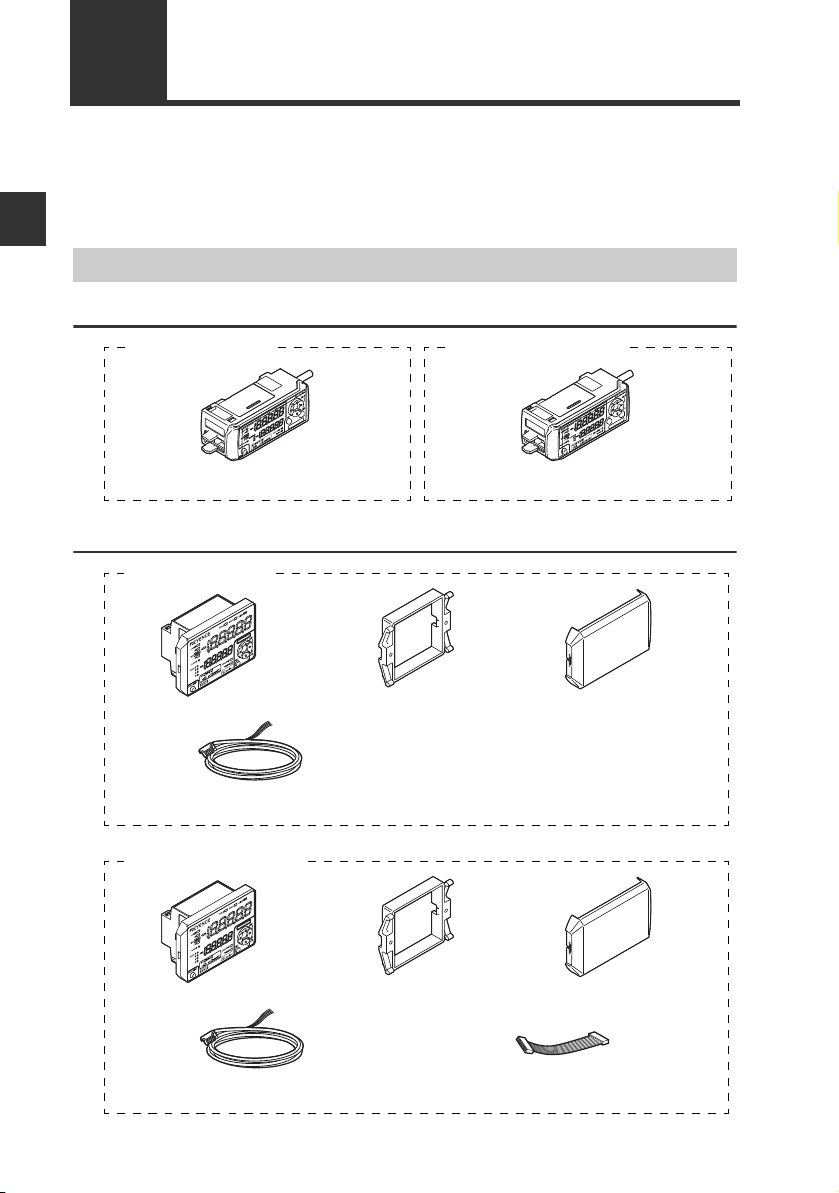
Sensor amplifier x 1
Instruction manual x 1
Sensor amplifier x 1
IL-1000 (main unit)
IL-1050 (expansion unit)
IL-1500 (main unit)
Sensor amplifier x 1 Panel mounting
bracket x 1
Front protection
cover x 1
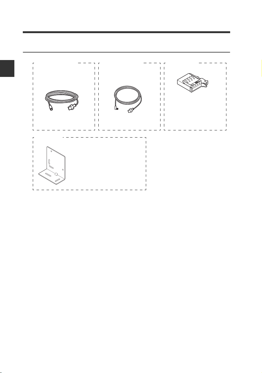
Power/Input-output cable (2 m) x 1
(12 cores)
Instruction manual x 1
IL-1550 (expansion unit)
Sensor amplifier x 1 Panel mounting
bracket x 1
Front protection
cover x 1
Input-output cable (2 m) x 1
(8 cores)
Expansion cable
(50 mm) x 1
Before Use
1-1 Checking the Package Contents
The following equipment and accessories are included in the package. Before using the
unit, make sure that all items are included.
We have thoroughly inspected the package contents before shipment. However, in the
event of defective or broken items, contact your nearest KEYENCE office.
Sensor Amplifier
DIN rail mount type
Panel mount type
1-2
IL-E
Page 15
Sensor Head
Sensor head x 1
Mounting bracket x 1
Insulating sheet x 1
Flat nut x 1
M3 x L30 screw x 2
Sensor head x 1
Mounting bracket x 1
Insulating sheet x 1
Flat nut x 1
M3 x L30 screw x 2
Laser warning sticker x 1
IL-030 (30 mm type) IL-S025 (25 mm type)
IL-S065 (65 mm type)
IL-065 (65 mm type)
IL-100 (100 mm type)
Sensor head x 1
Mounting bracket x 1
Insulating sheet x 1
Flat nut x 1
M4 x L35 screw x 2
Laser warning sticker x 1
IL-300 (300 mm type)
IL-600 (600 mm type)
IL-2000 (2000 mm type)
Sensor head x 1
M5 x L60 screw x 2
Laser warning sticker x 1
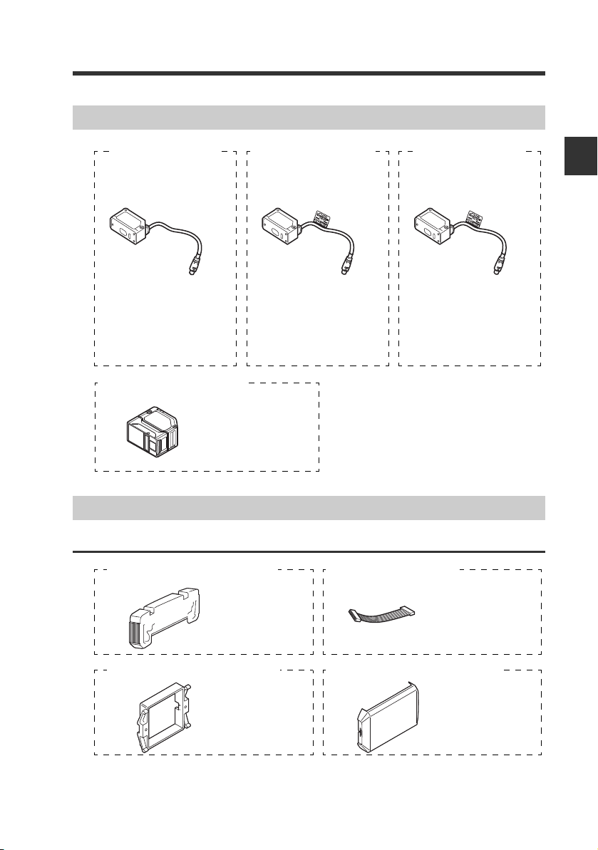
End unit
x 2
Expansion cable
(300 mm) x 1
OP-26751 (For IL-1000/IL-1050) OP-35361 (For IL-1550)
Panel mounting
bracket x 1
Front protection
cover x 1
OP-4122 (For IL-1500/IL-1550) OP-87076 (For IL-1500/IL-1550)
1-1 Checking the Package Contents
1
Before Use
List of Optional Parts
For sensor amplifier
IL-E
1-3
Page 16
1-1 Checking the Package Contents
Sensor head connection cable
(M8 straight connector) x 1
Sensor head
cable connector x 2
OP-87056 (2 m)
OP-87057 (5 m)
OP-87058 (10 m)
OP-87059 (20 m)
OP-84338
Sensor head connection cable
(M8 L-shaped connector) x 1
OP-87660 (2 m)
OP-87661 (5 m)
OP-87662 (10 m)
OP-87663 (20 m)
IL-2000 head mounting bracket x 1
Flat nut x 1
M5 x L60 screw x 2
OP-87606
For sensor head
1
Before Use
1-4
IL-E
Page 17
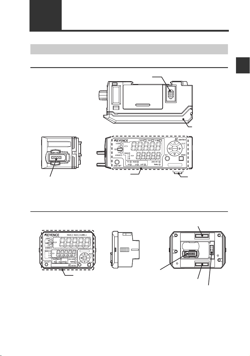
1-2 Part Names and Functions
Expansion unit connector*
1
Amplifier control
unit cover
Amplifier control unit
Sensor head connector
Expansion unit
connector*
2
Sensor Amplifier Unit
DIN rail mount type (IL-1000/IL-1050)
*1 When shipped from the factory, a protective cover is installed over the expansion slots.
*2 It is not installed on the main unit (IL-1000).
Panel mount type (IL-1500/IL-1550)
Expansion unit connector
1
(upper)*
1
Before Use
*1 It is not installed on the main unit (IL-1500).
*2 When shipped from the factory, a protective seal is attached.
IL-E
Amplifier control unit
Sensor head connector
Expansion unit connector (lower)*
2
Power/Input-output
cable connector
1-5
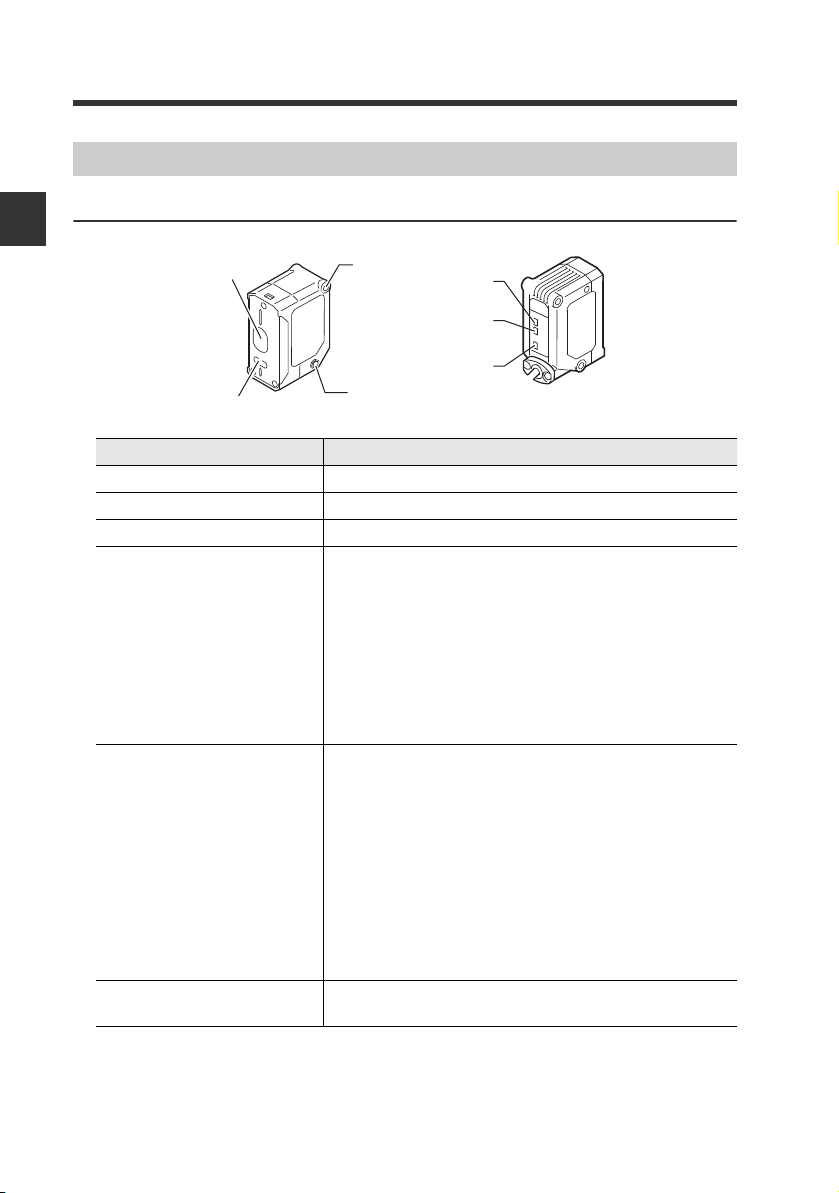
Page 18
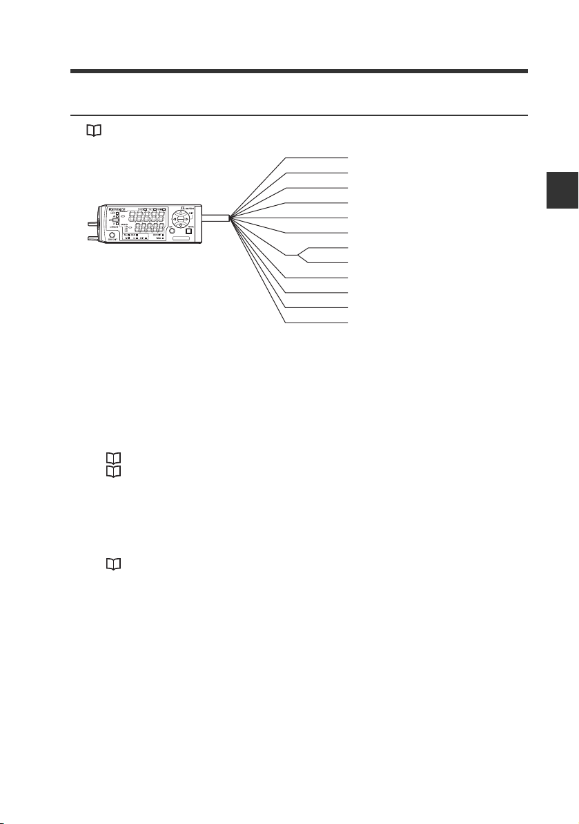
1-2 Part Names and Functions
(11) (12)(10)(6)
(16) (15) (14)
(1)
(2)
(3)
(4)
(7) (8) (9)
(13)
(5)
(11) (12)(10)(6)
(16) (15) (14)
(1)
(2)
(3)
(4)
(5)
(7) (8) (9)
(13)
Amplifier control unit
DIN rail mount type (IL-1000/IL-1050)
1
Before Use
Panel mount type (IL-1500/IL-1550)
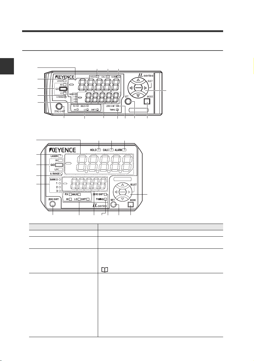
Item Description
(1) Main display Displays the judgment value (P.V.) and each setting item.
(2) Laser warning emission
indicator
(3) Judgment indicator
(4) Analog range indicator
Lights up while the laser beam is being emitted.
Blinks while the laser beam emission is stopped.
Displays whether the judgment value (P.V.) is HIGH (over the
upper limit), GO (within the acceptable range) or LOW (below
the lower limit) against the tolerance setting value.
"3-4 Setting the Tolerance Setting Value" (page 3-10)
Lights up when the P.V. (judgment value) is within the analog
output range. If the analog output setting is OFF, or when
using the expansion unit, the indicator lights within the
following detection range.
• IL-S025: 25 ± 5 mm
• IL-030: 30 ± 5 mm
• IL-S065/IL-065: 65 ± 10 mm
• IL-100: 100 ± 20 mm
• IL-300: 300 ± 140 mm
• IL-600: 600 ± 400 mm
• IL-2000: 2000 ± 1000mm
1-6
IL-E
Page 19
1-2 Part Names and Functions
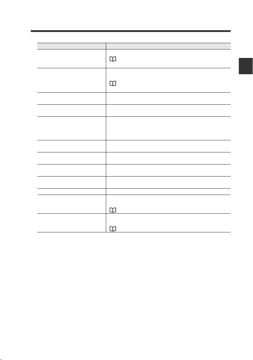
Item Description
Displays a bank in use.
(5) Bank indicator
(6) Zero shift button
(7) Sub display indicator
(8) Sub display
(9) Timing input indicator
(10) Zero shift indicator
(11) SET button
(12) MODE button
(13) Arrow button
(14) Alarm indicator Lights up in the alarm state or error state.
(15) Calculation indicator
(16) Hold indicator
"3-6 Bank Function (Registering Multiple Tolerance
Setting Values)" (page 3-20)
Press this button to match the internal measurement value
(R.V.) to the shift target value.
"3-5 Zero Shift Function (Shifting the Internal
Measurement Value (R.V.))" (page 3-18)
Lights up according to the type of values displayed on the
sub display.
Displays the internal measurement value (R.V.), analog
output value and each setting (selection) item.
Lights up while the timing input is ON when the timing input
(external input) is set to Level. Lights on approx. 0.5 sec.
when the timing input is set to Edge and the timing input is
turned ON.
The zero shift indicator will light up for approx. 0.5 second
when the zero shift function is used.
Used to automatically adjust the setting values when setting
each item.
Used when setting each item, starting/ending the setting or
moving items.
Used when selecting settings, changing display contents on
the sub display, etc.
Lights up when calculation is in process using the calculation
function.
"4-3 Calculation Function" (page 4-42)
Lights up when the Judgment Value (P.V.) is held and when
the step count filter is used.
"6. Hold Function" (page 4-15)
1
Before Use
IL-E
1-7
Page 20
1-2 Part Names and Functions
(1)
(2)
(3)
(3)
(4)
(5)
(6)
Sensor Head Unit
IL-S025/IL-030/IL-S065/IL-065/IL-100/IL-300/IL-600/IL-2000
1
Before Use
Item Description
(1) Laser receiver Laser receiver port. The surface is covered with glass.
(2) Laser transmitter Laser emission port. The surface is covered with glass.
(3) Mounting section Screwed onto dedicated bracket, etc.
(4) Reference distance
indicator
(5) Analog range indicator
(6) Laser warning emission
indicator
IL-030
CENTER
A. RANGE
LASER
By default (normal display mode), and "17. Head Display
Mode" (page 4-40), the reference distance indicator lights
within the following detection range.
• IL-S025: 25 mm ± 0.25 mm
• IL-030: 30 mm ± 0.25 mm
• IL-S065/IL-065: 65 mm ± 0.5 mm
• IL-100: 100 mm ± 1 mm
• IL-300: 300 mm ± 7 mm
• IL-600: 600 mm ± 20 mm
• IL-2000: 2000 mm ± 50 mm
By default (normal display mode), the analog range indicator
lights when the P.V. (judgment value) is within analog output
range. The indicator lights within the following detection
range, when the analog output setting is OFF and with the
expansion units.
• IL-S025: 25 mm ± 5 mm
• IL-030: 30 mm ± 5 mm
• IL-S065/IL-065: 65 mm ± 10 mm
• IL-100: 100 mm ± 20 mm
• IL-300: 300 mm ± 140 mm
• IL-600: 600 mm ± 400 mm
• IL-2000: 2000 ± 1000 mm
Lights up while the laser beam is being emitted.
Blinks while the laser beam emission is stopped.
1-8
IL-E
Page 21

Installation and Connection2
This chapter describes precautions when installing and
connecting the IL Series.
2-1 Mounting and Wiring the Sensor Amplifier ........ 2-2
2-2 Connecting and Mounting the Sensor Head....... 2-8
2
IL-E
2-1
Page 22
2
(1)
(2)
(3)
CAU
Point
Installation and Connection
2-1
Mounting and Wiring the Sensor Amplifier
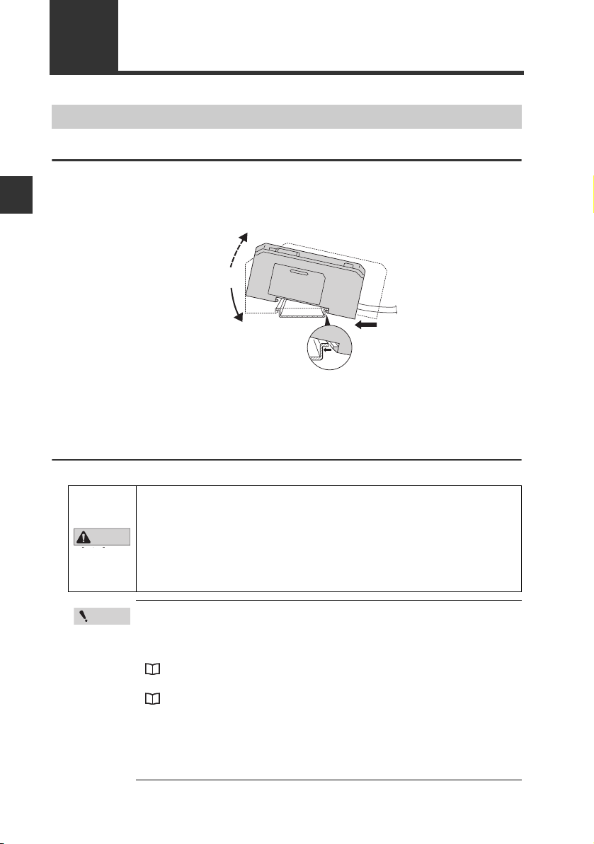
Mounting the Sensor Amplifier
DIN rail mount type, main unit (IL-1000)
Align the claw at the bottom of the main body with the DIN rail. While
1
pushing the main body in the direction of the arrow (1), slant it in the
direction of the arrow (2).
To dismount the sensor, raise the main body in the direction of the arrow
2
(3) while pushing the main body in the direction of the arrow (1).
DIN rail mount type, expansion unit (IL-1050)
Up to 7 expansion units can be connected to one main unit.
• Always mount expansion units onto a DIN rail.
• When connecting multiple amplifiers (expansion units), first check
CAUTION
2-2
to make sure that the power is turned OFF to all of the main and
expansion units. Connecting the units with the power turned ON
may cause damage to the units.
• Push the amplifiers (expansion units) as close as possible the
main unit. Improper connections may damage the equipment.
• When connecting the expansion units, make sure to initialize the
connected expansion units and set the output polarity.
(1) When turning on the amplifier for the first time after connecting
the sensor head
"3-1 Operation When the Power is Turned on for the First Time" (page 3-2)
(2) When performing the initial reset
"3-3 Initial Reset (Initialize)" (page 3-8)
• Expansion units with different setting of output polarity (such as
an NPN output expansion unit to a PNP output main unit) cannot
be connected together.
• Expansion units of DIN rail mount type cannot be connected to the
main unit of panel mount type.
IL-E
Page 23
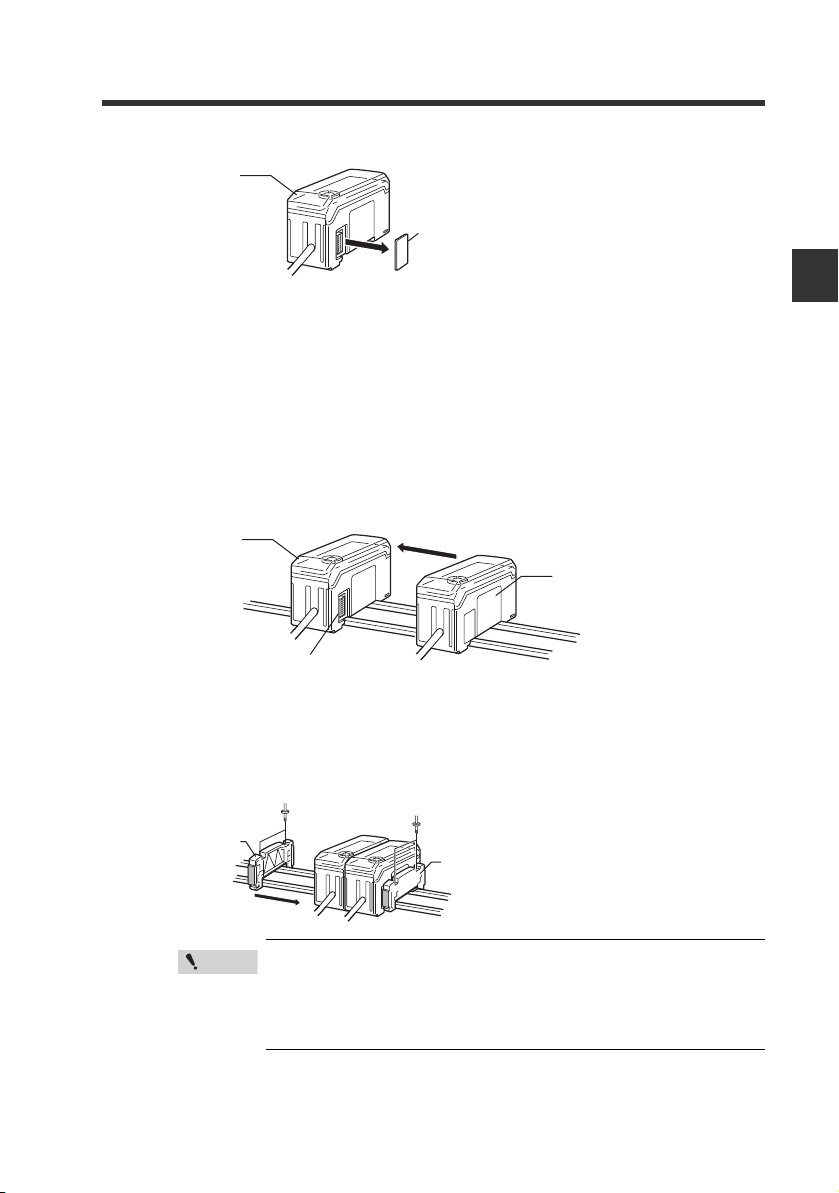
2-1 Mounting and Wiring the Sensor Amplifier
Point
Connector cover
Main unit
End unit
End unit
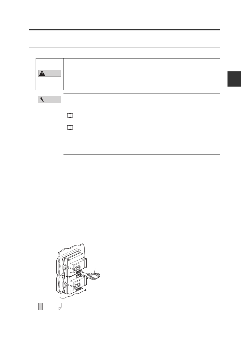
Remove the expansion protective cover from the IL-1000 (main unit).
1
Install the amplifiers (expansion units) on the DIN rail.
2
Refer to "DIN rail mount type, main unit (IL-1000)" (page 2-2) for details about how to
mount.
Push the expansion unit into the main unit connector until a clicking
3
sound can be heard.
The expansion unit installed next to the main unit is referred to as expansion unit 1.
Subsequent expansion units are referred to as expansion unit 2, expansion unit 3,
etc.
Main unit
Expansion unit 1
Connecter
2
Installation and Connection
IL-E
Install the end units (OP-26751: 2 units in a set) (optional accessory) on
4
both sides of the amplifiers (main and expansion units). Secure the end
units in place with screws on top (2 on each end unit).
The end units are mounted in the same way as the amplifiers.
Fix the amplifiers securely using the end units (OP-26751: 2
units in a set) (optional accessory) or commercially available
DIN rail fixing tool to prevent the amplifiers from slipping the
DIN rail or coming off from the DIN rail due to machine
vibration.
2-3
Page 24
2-1 Mounting and Wiring the Sensor Amplifier
45 mm
X mm
+ 0.6
− 0
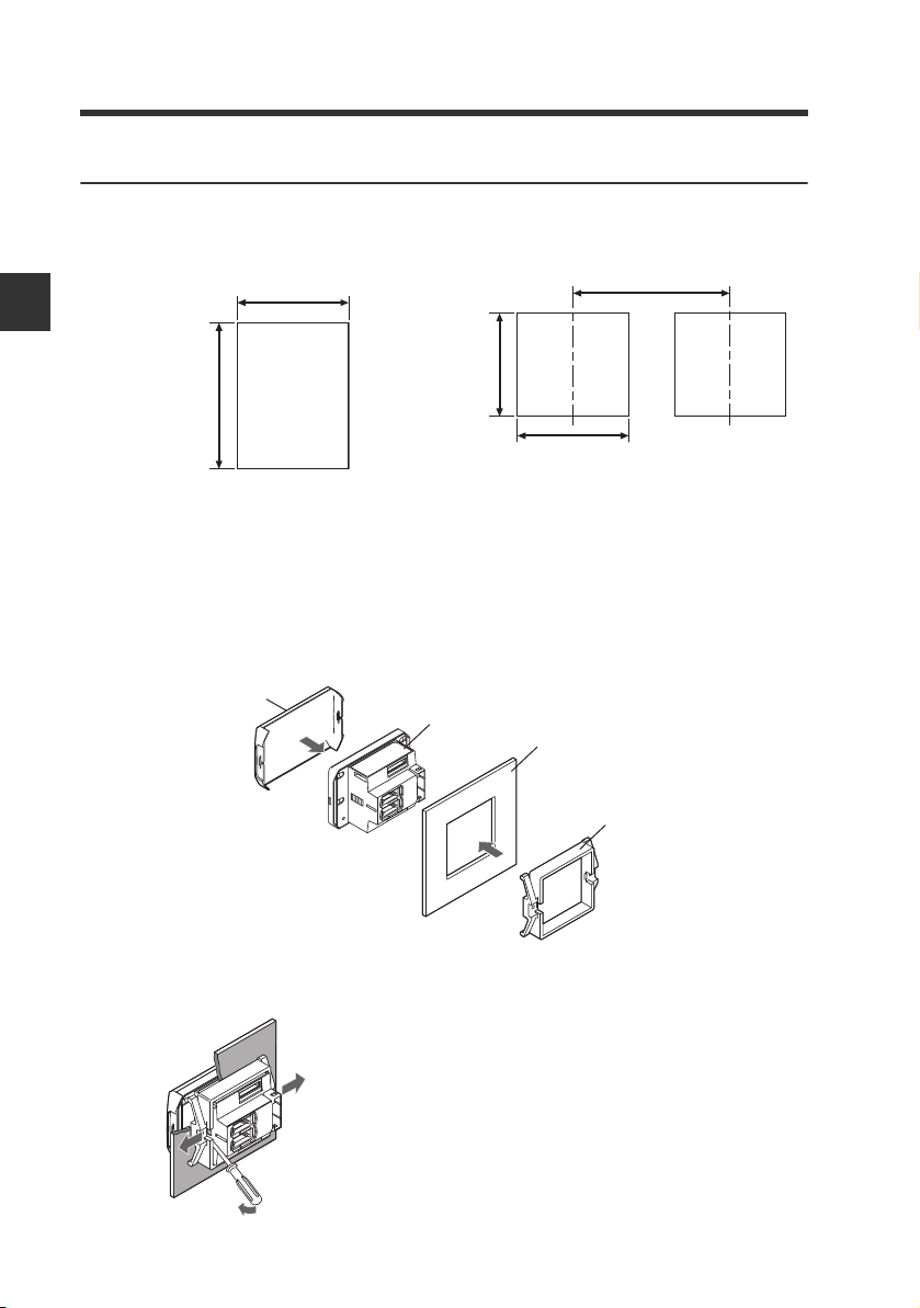
Panel mount type, main unit (IL-1500)
Make a hole on the panel as shown in the diagrams below.
1
When stacking the units vertically. When stacking the units horizontally.
2
Installation and Connection
• Panel thickness 1 to 6 mm
• X=48 x (number of amplifiers) -3
Insert the amplifier into the panel.
2
Arrange the panel mounting bracket as shown below, attach the bracket
3
to the amplifier from the back and attach the front protection cover to the
amplifier.
Front protection cover
45 mm
+ 0.6
− 0
Sensor amplifier
45 mm
Panel
Min. 85 mm
+ 0.6
− 0
2-4
Panel mounting bracket
To remove the panel mounting bracket, widen the claws at both ends of the panel
mounting bracket using a screwdriver, etc. and remove alternately.
IL-E
Page 25
2-1 Mounting and Wiring the Sensor Amplifier
CAU
CAUTION
Point
Reference
Expansion cable
Panel mount type, expansion unit (IL-1550)
Up to 7 expansion units can be connected to one main unit.
• Turn OFF the power before connecting the expansion cable.
Inserting or removing the cable with the power turned on may
cause damage to the units.
• Be sure to completely connect the expansion cable. Improper
connections may damage the equipment.
• When connecting the expansion units, make sure to initialize the
connected expansion units and set the output polarity.
When turning on the amplifier for the first time after connecting the sensor head
(1)
"3-1 Operation When the Power is Turned on for the First Time" (page 3-2)
(2) When performing the initial reset
"3-3 Initial Reset (Initialize)" (page 3-8)
•
Expansion units with different setting of output polarity (such as an NPN output
expansion unit to a PNP output main unit) cannot be connected together.
• Expansion units of panel mount type cannot be connected to the
main unit of DIN rail mount type.
Make holes on the panel to attach according to the number of amplifiers
1
(connected expansion units).
For the panel cutout dimensions, refer to the "Panel mount type, main unit (IL-1500)" (page 2-4).
Install the amplifiers (expansion units) on the panel.
2
For the amplifier mounting method, refer to the "Panel mount type, main unit
(IL-1500)" (page 2-4).
2
Installation and Connection
3
IL-E
Connect the amplifier (main unit) and amplifier (expansion unit) using the
expansion cable (50 mm) supplied with the expansion unit.
The expansion unit installed next to the main unit is referred to as expansion unit 1.
Subsequent expansion units are referred to as expansion unit 2, expansion unit 3, etc.
When arranging the amplifiers side by side, the expansion cable of 300 mm
(OP-35361) is necessary.
2-5
Page 26
2-1 Mounting and Wiring the Sensor Amplifier
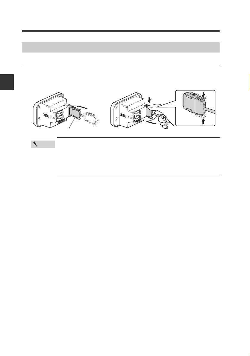
Power/Input-output cable
To attach To remove
Sensor Amplifier Wiring
Connecting power/Input-output cable (only for panel mount type)
Connect the power/input-output cable to the panel mount type main unit and connect the
input-output cable to the expansion units.
2
Installation and Connection
Point
• The power/input-output cable for the main unit has 12 core wires,
and the Input-output cable for the expansion units has 8.
• Power for the expansion units is supplied from the main unit.
• If the input-output is not used for the expansion units, cut the
cable at the connector base or terminate the wires properly for
future use.
2-6
IL-E
Page 27
2-1 Mounting and Wiring the Sensor Amplifier
Brown
Blue
Black
White
Gray
Light blue
Orange
Shield
Pink
Yellow
Pink/Purple
Purple
Green
10 to 30 VDC
0 V
HIGH judgment output
LOW judgment output
GO judgment output
Analog output +
Analog output GND
External input 1 (Zero shift input)
External input 2 (Reset input)
External input 3 (Timing input)
External Input 4 (Not in use)
Alarm output
*1
*1
*1
*2
*2
*3
*3
*3
*3
Power/Input-output cable
"Output Circuit Diagram" (page 5-5)
*1 IL-1050/IL-1550 (expansion units) do not have brown, blue or light blue wires.
Power is supplied to the expansion units through IL-1000/IL-1500 (main unit).
*2 The analog output can be set to any of the following options either "When the power is
turned on for the first time" or "When performing the initial reset".
• Not used (OFF)
• 0 to 5 V
• -5 to 5 V
• 1 to 5 V
• 4 to 20 mA
"3-1 Operation When the Power is Turned on for the First Time" (page 3-2)
"3-3 Initial Reset (Initialize)" (page 3-8)
*3 The external input can be selected among the following in addition to the above.
• Bank A input
• Bank B input
• Laser emission stop input
• Not used (OFF)
Gain input only be selected for external input 4.
"11. External Input" (page 4-30)
*4 When expanding to six or more units, use a power supply that provides 20 to 30 V.
2
Installation and Connection
IL-E
2-7
Page 28
2
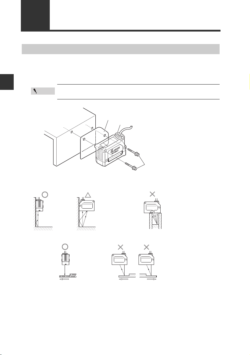
Insulating sheet
Sensor head
Screws included
with the head
Intelligent-L
AVOID EXPOSURE
LASER RADIATION IS EMITTED
FROM THIS APERTURE
IL
-
030
Tightening torque:
1.2 Nm (12kgf•cm) or less
(IL-S025/IL-030/IL-S065/IL-065/
IL-100)
2.7 Nm (27kgf•cm) or less
(IL-300/IL-600)
3.0 Nm (30kgf•cm) or less
(IL-2000)
• The stray
reflections
from the wall
have little
effect.
• Variations in
the detection
value are
possible due
to stray laser
light.
• The target
cannot be
detected when
the transmitter or
receiver is
blocked.
• Stable
detection
even on
uneven
areas.
• Incorrect values
can be detected
on uneven
areas.
Installation and Connection
2-2
Connecting and Mounting the Sensor Head
Mounting the Sensor Head
Attach the sensor head using the dedicated mounting bracket.
When the dedicated bracket is not used, place the included insulation sheet between the
mounting surface and the sensor head as indicated in the diagram. (When the dedicated
bracket is used, or when the IL-2000 is used, the insulation sheet is unnecessary.)
Point
The optical axis may vary by approximately ±1.5° (IL-S025/IL-S065/
±
IL-2000), or
2.0° (IL-030/IL-065/IL-100/IL-300/IL-600).
z Mounting when detecting targets
close to a wall
z When detecting uneven workpieces
2-8
z Mounting when detecting targets in
a hole
IL-E
Page 29
2-2 Connecting and Mounting the Sensor Head
Point
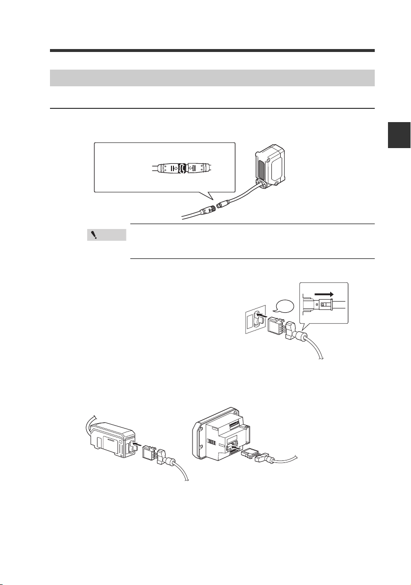
(1) Align the arrow position of the connector to insert.
(2) Rotate the connector screw to tighten.
* For the IL-2000, the direct connector will come out
directly from the sensor head, so there is no arrow.
Connection and Wiring
Connecting the sensor head and amplifier
Attach the sensor head connection cables to the sensor head cable
1
Tighten the connectors securely by hand.
If they are loose, the IP67 environmental resistance rating
cannot be guaranteed.
Attach the sensor head connection cable to the amplifier connector.
2
Remove the lock cover of the connector and
insert it into the connectors of amplifier until a
clicking sound is heard.
Click
2
Installation and Connection
Lock cover
Unlocked
DIN rail mount type
(IL-1000/IL-1050)
IL-E
Panel mount type
(IL-1500/IL-1550)
2-9
Page 30
2-2 Connecting and Mounting the Sensor Head
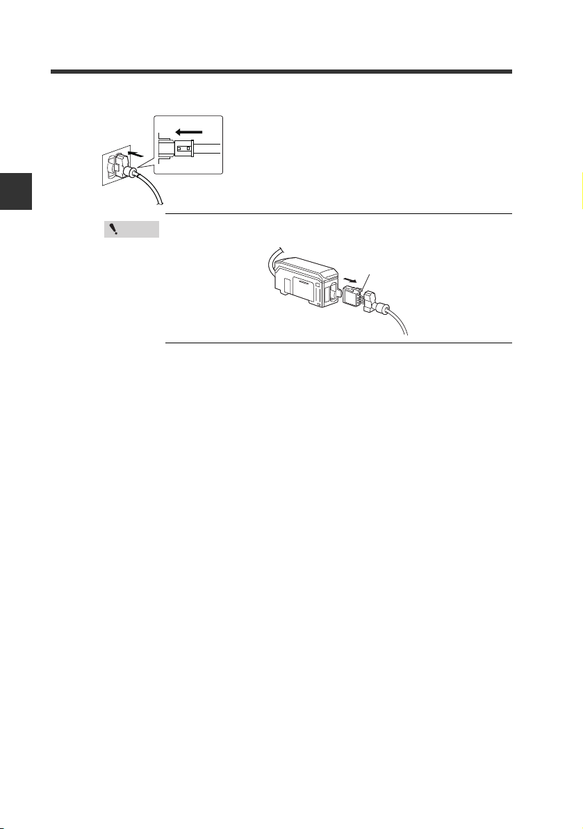
Lock lever
Attach the lock cover to the connector to secure the cable.
3
Lock cover
Locked
2
Installation and Connection
Point
When removing the sensor head connection cable, push the
lock lever and pull it out.
2-10
IL-E
Page 31

2-2 Connecting and Mounting the Sensor Head
Point
Point
Blue
White
Black
Brown
Insert further
than here.
Attaching the sensor head cable connector (OP-84338: optional accessory)
Cut the sensor head connection cable to the required length and attach the new connector
to use the sensor. The attaching method is the same for both transmitter and receiver.
Cut the cable to the required length and strip approx. 15 mm of insulation
1
from the end of the cable.
Do not strip the core wire insulation.
Insert each cable to the end matching to the same color marks on the
2
connector.
The cables should be inserted to the end and held in place.
2
Installation and Connection
IL-E
Confirm that all cables are inserted to the specified position and crimp
3
them using pliers or a similar tool.
If the connector is changed, make sure to connect it to the
amplifier and confirm the normal operation.
If it does not operate normally, crimp the connector again with
pliers.
Once the connector is crimped, it cannot be reused.
2-11
Page 32

2-2 Connecting and Mounting the Sensor Head
2
Installation and Connection
MEMO
2-12
IL-E
Page 33

Basic Operations3
This chapter describes basic operations and settings for the IL
Series.
Operation When the Power is Turned on for the First Time
3-1
3-2 Operations on the Main Screens ......................... 3-3
3-3 Initial Reset (Initialize) .......................................... 3-8
3-4 Setting the Tolerance Setting Value .................. 3-10
3-5
Zero Shift Function (Shifting the Internal Measurement Value (R.V.))
3-6
Bank Function (Registering Multiple Tolerance Setting Values)
3-7 Key Lock Function .............................................. 3-21
....... 3-2
.... 3-18
.... 3-20
3
IL-E
3-1
Page 34

3
Point
Powe r ON
Setting value
Description
npn
NPN output
pnp
PNP output
Setting value
Description
off
Not output
0-5 u
Analog output after the judgment value (P.V.) is converted to
the range from 0 to 5 V.
-5-5 u
Analog output after the judgment value (P.V.) is converted to
the range from -5 to 5 V.
1-5 u
Analog output after the judgment value (P.V.) is converted to
the range from 1 to 5 V.
ampr
Analog output after the judgment value (P.V.) is converted to
the range from 4 to 20 mA.
Basic Operations
3-1
Operation When the Power is Turned on for the First Time
When the amplifier is turned on for the first time after the sensor head is connected, the
initial setting screen appears after a few seconds. Make the initial settings according to the
following procedure.
The initial setting is necessary for both the main unit and the expansion units when units
are added.
Once the initial setting is completed, the initial setting display will
not appear when the power is turned on the second time or the after.
To change these settings, perform an initial reset.
"3-3 Initial Reset (Initialize)" (page 3-8)
LASER
GO
ALIGNMENT
HI
LO
BANK
R.V.
HOLD CALC
QWV
0
1
2
PRP
3
ZERO SHIFT
ANALOG
HI SHIFT
LO
TIMING
Output polarity
Press S/T button to select the polarity of judgment
1
output and edge check output, and then press [MODE]
button.
CHECK
[MODE] button
CHECK
LASER
GO
ALIGNMENT
HI
LO
BANK
0
1
2
3
R.V.
HI SHIFT
HOLD CALC
#P.)
QHH
ZERO SHIFT
ANALOG
LO
TIMING
Analog output
Press S/T button to select the type of analog output
2
and press [MODE] button. (for IL-1000 / IL-1500 only)
[MODE] button
"10. Analog Output Scaling" (page 4-27)
CHECK
HOLD CALC
LASER
HI
GO
LO
BANK
0
1
ALIGNMENT
2
'PF
3
ZERO SHIFT
ANALOG
R.V.
HI SHIFT
LO
TIMING
Make other settings as necessary.
4
After the setting is complete, [end] blinks several
3
times on the sub display and the main screen
appears.
3-2
IL-E
Page 35

3-2 Operations on the Main Screens
LASER
BANK
0
1
2
3
HI
GO
LO
R.V.
ANALOG
HI SHIFT
ZERO SHIFT
TIMING
LO
ALIGNMENT
HOLD CALC
CHECK
LASER
BANK
0
1
2
3
HI
LO
R.V.
ANALOG
HI SHIFT
ZERO SHIFT
TIMING
LO
ALIGNMENT
[HOLD] ON
GO
HOLD CALC
CHECK
LASER
BANK
0
1
2
3
HI
LO
R.V.
ANALOG
HI SHIFT
ZERO SHIFT
TIMING
LO
ALIGNMENT
HOLD CALC
CHECK
GO
[CALC] ON
R.V. (Internal Measurement Value) and P.V. (Judgment Value)
This section describes R.V. (Internal Measurement Value) displayed on the sub display
(lower level) and P.V. (Judgment Value) displayed on the main display (upper level).
R.V. (Internal Measurement Value)
R.V. (Internal Measurement Value) is the value displayed when a target is inserted into the
measurement range.
* R.V. = Raw Value
P.V. ( Jud g me n t Va lu e )
P.V. (Judgment Value) is the value to set the judgment output to ON/OFF according to the
tolerance setting value. Also, the analog output is output based on the P.V..
* P.V. = Present Value
"3-4 Setting the Tolerance Setting Value" (page 3-10)
The Judgment value (P.V.) and the Internal Measurement Value (R.V.) are in general the
same value. However, when the hold function or step-count filter is used, or when only the
calculation function is used, they will become different values.
"6. Hold Function" (page 4-15)
"4-3 Calculation Function" (page 4-42) (page 4-39)
Main Display (Upper Level)
The judgment value (P.V.) is displayed on the main display.
The display varies as below according to each function to be used such as Normal, Hold
function, Calculation function.
Normal
The same value as the internal measurement value (R.V.) is displayed
as a judgment value (P.V.).
When the hold function is used, when the step count filter is used
The judgment value (P.V.) is held according to the hold function settings.
The Judgment Value (P.V.) is held according to the step count filter
settings if they are stepped and acknowledged.
"6. Hold Function" (page 4-15)
"3. Averaging rate, Step count filter, High-pass filter" (page 4-9)
When the calculation function is used
Main unit:
Expansion unit: The same display as for Normal
"4-3 Calculation Function" (page 4-42) (page 4-39)
Displays the calculated result (calculation value) with the
calculation function as a judgment value (P.V.).
3
Basic Operations
Reference
When using both the hold function and calculation function with the main
unit, the hold indicator [HOLD] and calculation indicator [CALC] will light.
The judgment value (P.V.) on the main display will follow the hold function
settings. The calculated value (CALC value) will be held and displayed as
the judgment value (P.V.)
IL-E
3-3
Page 36

3-2 Operations on the Main Screens
(1) R.V. display screen
(6) Calculated value display screen
* Displayed only for the main
unit and when the calculation
function is used.
* Displayed only for the
main unit and when the
analog output is used.
(2) Analog output screen
(5) Shift target value setting screen
(3) HIGH side setting value screen
(4) LOW side setting value screen
*1 (6) [CALc] displayed for
approx. 2 seconds when
calculated value display
screen appears.
Sub Display (Lower Level)
The sub display can be switched with the arrow button W/X.
According to the type of displayed value, the sub display indicator [R.V. / ANALOG / HI / LO
/ SHIFT] lights up.
3
Basic Operations
LASER
HI
GO
[R.V.]
LO
ALIGNMENT
BANK
ON
HOLD CALC
R.V.
0
1
2
3
ZERO SHIFT
R.V.
ANALOG
HI SHIFT
LO
CHECK
TIMING
LASER
HI
GO
All
LO
BANK
0
1
ALIGNMENT
OFF
2
3
R.V.
ANALOG
HI SHIFT
LO
LASER
Shift target value
HI
GO
LO
BANK
0
1
ALIGNMENT
2
[SHIFT]
3
ANALOG
R.V.
ON
HI SHIFT
LO
HOLD CALC
CHECK
CALC value
ZERO SHIFT
TIMING
CHECK
HOLD CALC
ZERO SHIFT
TIMING
*1
LASER
GO
ALIGNMENT
[ANALOG]
LASER
HIGH side setting value
GO
ALIGNMENT
[HI]
ON
LASER
LOW side setting value
HI
GO
LO
BANK
0
1
ALIGNMENT
2
[LO]
3
R.V.
ON
HI SHIFT
CHECK
HOLD CALC
ZERO SHIFT
ANALOG
LO
TIMING
HOLD CALC
Analog output
HI
LO
BANK
0
1
2
W
3
ANALOG
R.V.
ON
HI SHIFT
LO
HOLD CALC
HI
LO
BANK
0
1
2
3
R.V.
ANALOG
LO
HI SHIFT
CHECK
ZERO SHIFT
TIMING
CHECK
ZERO SHIFT
TIMING
3-4
IL-E
Page 37

3-2 Operations on the Main Screens
(1) R.V. display screen
The internal measurement value (R.V.) is displayed. The displayed value is not held.
(2) Analog output screen (Displayed when using main unit's analog output)
The voltage value (unit: V) or current value (unit: mA) of the analog output is displayed.
"3-1 Operation When the Power is Turned on for the First Time" (page 3-2)
"3-3 Initial Reset (Initialize)" (page 3-8)
(3) HIGH side setting value screen
The upper limit of the acceptable range (tolerance setting value) for the object is
displayed. Also, the setting value can be changed. If the judgment value (P.V.) exceeds
the value set here, the HIGH judgment output turns on.
"3-4 Setting the Tolerance Setting Value" (page 3-10)
(4) LOW side setting value screen
The lower limit of the acceptable range (tolerance setting value) for the object is
displayed. Also, the setting value can be changed. If the judgment value (P.V.) falls
below the value set here, the LOW judgment output turns on.
"3-4 Setting the Tolerance Setting Value" (page 3-10)
(5) Shift target value screen
When the zero shift button is pressed or the zero shift input is set to ON, the internal
measurement value (R.V.) is adjusted to the value set here.
"3-5 Zero Shift Function (Shifting the Internal Measurement Value (R.V.))" (page 3-18)
(page 3-18)
3
Basic Operations
(6) Calculation value screen (Displayed when using main unit's calculation function)
The calculated value (CALC value) is displayed. The displayed value is not held.
"4-3 Calculation Function" (page 4-42) (page 4-39)
IL-E
3-5
Page 38

3-2 Operations on the Main Screens
LASER
BANK
0
1
2
3
HI
GO
LO
R.V.
ANALOG
HI SHIFT
ZERO SHIFT
TIMING
LO
ALIGNMENT
HOLD CALC
CHECK
Setting Operations
This section explains functions operable on the main screen and functions operable after
the display changes to each setting screen.
Functions Operable on the Main Screen
DIN rail mount type (IL-1000/IL-1050) Panel mount type (IL-1500/IL-1550)
3
Basic Operations
Main screen
Buttons used
Press W or X button.
Switching display on the sub display (lower level) (page 3-4)
Any of the internal measurement value (R.V.), analog output
value, HIGH side setting value, LOW side setting value or shift
target value are displayed and the settings can be changed.
3-4 Setting the Tolerance Setting Value (page 3-10)
HIGH side setting value and LOW side setting value are set. The judgment is
made among HIGH/GO/LOW, and the value is displayed and output.
3-5 Zero Shift Function (Shifting the Internal Measurement
Value (R.V.)) (page 3-18)
The internal measurement value (R.V.) can be shifted (offset)
to an arbitrary shift target value.
While pressing down [MODE], press S or T button.
3-6 Bank Function (Registering Multiple Tolerance Setting Values) (page 3-20)
HIGH side setting value, LOW side setting value, shift target
value, and analog output scaling upper / lower limit value can
be saved at up to four banks and switched.
Press [MODE] and S buttons for approx. 2 seconds.
or
Press [MODE] and T buttons for approx. 2 seconds.
3-7 Key Lock Function (page 3-21)
This function prevents unwanted button operations during measurement.
3-6
IL-E
Page 39

Available Functions from the Main Screen
LASER
BANK
0
1
2
3
HI
GO
LO
R.V.
ANALOG
HI SHIFT
ZERO SHIFT
TIMING
LO
ALIGNMENT
HOLD CALC
CHECK
Main screen
Press [MODE] button for approx. 2 seconds.
4-2 Basic Settings and Advanced Settings (page 4-4)
Basic settings
Basic settings such as measurement mode, response time
are made.
Advanced settings
More advanced settings such as hold function, delay timer
enable the unit to be used in wider applications.
Press [MODE] and W buttons for approx. 2 seconds.
4-3 Calculation Function (page 4-42)
The internal measurement value (R.V.) of two sets of the
sensor amplifier can be calculated (addition or subtraction).
Press [MODE] and X buttons for approx. 2 seconds.
4-4 Calibration Function (page 4-45)
When there is a difference between the internal
measurement value (R.V.) or calculated value (CALC value)
and the actual dimension of the object, the value can be
calibrated.
While pressing the [MODE] button, press the [SET] button 5
times.
3-3 Initial Reset (Initialize) (page 3-8)
All settings, excluding the calibration function, are initialized.
3-2 Operations on the Main Screens
3
Basic Operations
IL-E
3-7
Page 40

3
Reference
Setting value
Description
npn
NPN output
pnp
PNP output
Setting value
Description
off
Not output
0-5 u
Analog output after the judgment value is converted to the range from 0 to 5 V.
-5-5 u
Analog output after the judgment value is converted to the range from -5 to 5 V.
1-5 u
Analog output after the judgment value is converted to the range from 1 to 5 V.
aMpr
Analog output after the judgment value is converted to the range from 4 to 20 mA.
LASER
BANK
0
1
2
3
HI
LO
R.V.
ANALOG
HI SHIFT
ZERO SHIFT
TIMING
LO
ALIGNMENT
.QE
GO
HOLD CALC
CHECK
Basic Operations
3-3 Initial Reset (Initialize)
When initial reset is performed, all settings, excluding the calibration function, are initialized.
The judgment output's polarity and analog output setting can be changed with the same operation.
Main screen
HOLD CALC
LASER
HI
GO
LO
BANK
0
1
ALIGNMENT
2
3
ANALOG
R.V.
HI SHIFT
LO
While pressing the
[MODE] button,
press the [SET]
button 5 times.
HOLD CALC
LASER
HI
GO
T'5'V
LO
BANK
0
1
ALIGNMENT
2
3
ANALOG
R.V.
HI SHIFT
LO
Performing the initial reset
[MODE] button
HOLD CALC
LASER
HI
GO
LO
BANK
0
1
ALIGNMENT
2
3
ANALOG
R.V.
HI SHIFT
LO
Output polarity
[MODE] button
HOLD CALC
LASER
HI
GO
#P.)
LO
BANK
0
1
ALIGNMENT
2
3
ANALOG
R.V.
HI SHIFT
LO
Analog output
ZERO SHIFT
TIMING
;GU
ZERO SHIFT
TIMING
QWV
PRP
ZERO SHIFT
TIMING
QHH
ZERO SHIFT
TIMING
CHECK
CHECK
CHECK
CHECK
While pressing the [MODE] button on the main screen,
1
press the [SET] button 5 times.
[reset] is displayed on the main display (upper level).
Press S/T button to select [yes] and press the
2
[MODE] button.
If [no] is selected at this point, only the output polarity and analog
output settings can be changed without performing the initial reset.
Press S/T button to select the output polarity and
3
press the [MODE] button.
Press S/T button to select the analog output and
4
press the [MODE] button. (only for IL-1000 / IL-1500
only)
[MODE] button
LASER
GO
ALIGNMENT
HI
LO
BANK
HOLD CALC
T'5'V
0
1
2
3
ANALOG
R.V.
HI SHIFT
LO
Point
CHECK
'PF
ZERO SHIFT
TIMING
If the calculation function is used, perform the initial reset for the
main unit first.
After the initialization is complete, [
5
times on the sub display and the main screen is restored.
• When buttons other than the S/T button and [MODE] button are pressed
during the initial reset procedure, the initial reset is canceled and the
screen in step 2 is restored.
• When you attempt to initialize the unit while the key
lock function is set, the screen shown on the right
appears and the initialization fails.
3-8
Cancel the key lock before attempting to initialize the unit.
"3-7 Key Lock Function" (page 3-21)
"10. Analog Output Scaling" (page 4-27)
end
] blinks several
IL-E
Page 41

3-3 Initial Reset (Initialize)
GO
;QTP
LASER
BANK
0
1
2
3
HI
LO
R.V.
ANALOG
HI SHIFT
ZERO SHIFT
TIMING
LO
ALIGNMENT
T'5'V
HOLD CALC
CHECK
Operation for Changing the Model of Connected Head
If the model of the connected head has been changed, the zero shift function and
calibration function must be initialized.
The following display will appear when the connected head's model is changed.
Connect the head of different model into the amplifier.
1
[rESET] will appear on the main display, and [Y.or.n] will appear on the sub display.
Press S/T button to select [yes] and press the [MODE] button.
2
When [yes] is selected, all functions including the calibration function will be
initialized. After the initialization is complete, [End] blinks several times on the sub
display and the main screen is restored. When [no] is selected, the main screen is
restored. The zero shift function and calibration function will not be initialized.
3
Basic Operations
IL-E
3-9
Page 42

3
Basic Operations
3-4
The tolerance setting value consists of the upper limit value (HIGH side setting value) and
the lower limit value (LOW side setting value). By setting these values, judgments are made
in three levels: when the judgment value (P.V.) goes beyond the upper limit (HIGH
judgment), when the judgment goes beyond the lower limit (LOW judgment) and when the
judgment is within the acceptable range (GO judgment). Then, the judgment indicator and
judgment output are turned ON/OFF.
judgment
HIGH ON OFF OFF Red OFF OFF
GO OFF ON OFF OFF Green OFF
LOW OFF OFF ON OFF OFF Red
Error
*1 When the output state of judgment output is Normally Open (default value) ON/OFF is
reversed for Normal Close.
*2 The judgment indicator ON/OFF condition can be changed.
*3 "Error Displays and Corrective Actions" (page A-4)
DIN rail mount type (IL-1000/IL-1050) Panel mount type (IL-1500/IL-1550)
Setting the Tolerance Setting Value
judgment output
HIGH GO LOW HI GO LO
*3
ON OFF ON Red OFF Red
"5. Output State" (page 4-14)
"18. Display Color" (page 4-41)
*1
judgment indicator
*2
Judgment indicator
The tolerance setting value can be set either manually or automatically.
Item Setting Method
Manual setting
Automatic
setting
(When other
than step count
filter)
Automatic
setting
(When step
count filter)
Point
Tolerance tuning Detect the master workpiece and set the tolerance.
2 point tuning
2 point tuning Detect the step, set the tolerance.
1 point tuning
When setting the tolerance setting value manually using the two-point
tuning, make sure to set "HIGH side setting value
Directly enter the tolerance setting value (HIGH side
setting value, LOW side setting value).
Detect the good target and defective target and set the
tolerance.
Detect the present P.V. (Judgment Value), set the
tolerance.
3-10
>
LOW side setting value".
IL-E
Page 43

3-4 Setting the Tolerance Setting Value
Reference
GO
LASER
BANK
0
1
2
3
HI
LO
R.V.
ANALOG
HI SHIFT
ZERO SHIFT
TIMING
LO
ALIGNMENT
HOLD CALC
CHECK
[HI]
ON
HIGH side setting value
When setting "HIGH side setting value < LOW side setting value", the
judgment output is as follows.
GO judgment output is not output regardless of the judgment value (P.V.).
•
(When setting HIGH side setting value = LOW side setting value = judgment value
(P.V.) and setting the hysteresis to 0.000, GO judgment output is turned on.)
• When the judgment value (P.V.) goes beyond the HIGH side setting value
and falls below the LOW side setting value, the HIGH judgment output
and LOW judgment output are output at the same time.
Manual Setting
This is the method to directly enter the tolerance setting value (HIGH side setting value,
LOW side setting value).
Press the W / X button several times on the main screen. Then display the
1
HIGH side setting value on the sub display (lower level).
"Sub Display (Lower Level)" (page 3-4)
Press S / T button to set the HIGH side setting value.
2
IL-S025/IL-030/IL-S065/IL-065/IL-100
Item Setting range
HIGH side setting value -99.999 to 99.999 5.000
IL-300/IL-600
Item Setting range
HIGH side setting value -999.99 to 999.99 50.00
IL-2000
Item Setting range
HIGH side setting value -9999.9 to 9999.9 500.0
Press the X
3
display (lower level).
button once and display the LOW side setting value on the sub
Default value
Default value
Default value
3
Basic Operations
IL-E
LOW side setting value
[LO]
ON
3-11
Page 44

3-4 Setting the Tolerance Setting Value
Reference
Reference
Press S / T button to set the LOW side setting value.
4
IL-S025/IL-030/IL-S065/IL-065/IL-100
Item Setting range
LOW side setting value -99.999 to 99.999 -5.000
IL-300/IL-600
Item Setting range
LOW side setting value -999.99 to 999.99 -50.00
3
IL-2000
Item Setting range
Basic Operations
LOW side setting value -9999.9 to 9999.9 -500.0
After setting, press W / X button to return the sub display to the original display as
necessary.
As soon as the HIGH side setting value and the LOW side setting value are
entered, the judgment and output begin with the new setting value.
Automatic Setting (When other than step count filter)
Tolerance tuning
When the target (master workpiece) as a reference is present, the HIGH side setting value
(upper limit) and LOW side setting value (lower limit) can automatically be set with the
master workpiece measurement value as the center value.
When the tuning result exceeds the setting range, the limit value of the
setting range is considered as the setting value.
Default value
Default value
Default value
3-12
Point
The tolerance tuning cannot be performed when the judgment value
(P.V.) is displayed as [-----].
If attempting to perform, [no.uaL] blinks several times on the main
display.
Press the W / X button several times on the main screen. Then display the
1
R.V. display screen on the sub display (lower level).
"Sub Display (Lower Level)" (page 3-4)
HOLD CALC
LASER
HI
GO
[R.V.]
LO
BANK
0
1
ALIGNMENT
ON
2
3
R.V.
HI SHIFT
Measure the master workpiece and press the [SET] button.
2
CHECK
R.V.
ZERO SHIFT
ANALOG
LO
TIMING
The judgment value (P.V.) as a reference value for the tolerance setting is imported.
[
set
] and the tolerance setting width are displayed alternately on the sub display (lower level).
IL-E
Page 45

3-4 Setting the Tolerance Setting Value
Setting width
Measurement upper limit value
Measurement lower limit value
LOW side setting value (lower limit)
HIGH side setting value (upper limit)
Master target P.V. (reference value)
IL-S025/IL-030/IL-S065/IL-065/IL-100
IL-300/IL-600
IL-2000
Item Setting range
Default value
Setting width 0.000 to 99.999 0.200
Item Setting range
Default value
Setting width 0.00 to 999.99 2.00
Item Setting range
Default value
Setting width 0.0 to 9999.9 20.0
Press S / T button to set the tolerance setting width.
3
Master workpiece P.V.
LASER
HI
GO
LO
BANK
0
1
ALIGNMENT
2
3
R.V.
HI SHIFT
Tolerance setting width
Press the [SET] button to complete the tolerance tuning.
4
[set]
blinks on the main display (upper level), and the HIGH side setting value and LOW
ANALOG
LO
HOLD CALC
CHECK
ZERO SHIFT
TIMING
side setting value are determined. Then, the display returns to the R.V. screen automatically.
3
Basic Operations
IL-E
3-13
Page 46

3-4 Setting the Tolerance Setting Value
Reference
2 point tuning
With this method, the median value of the good target and defective target is set as the
tolerance setting value when there are good target and HIGH/LOW defective target.
When the tuning result exceeds the setting range, the limit value of the
setting range becomes the setting value.
Point
Two-point tuning is not performed if the internal measurement value
(R.V.) is [-----].
If performed, [no.uaL] will blink several times on the main display.
3
Press the W / X button several times on the main screen. Then display the
Basic Operations
1
HIGH side setting value on the sub display (lower level).
"Sub Display (Lower Level)" (page 3-4)
HOLD CALC
LASER
HIGH side setting value
HI
GO
LO
BANK
0
1
ALIGNMENT
2
[HI]
3
R.V.
ON
HI SHIFT
Measure the good target and press the [SET] button. (HIGH side 1st point
2
confirmation operation)
CHECK
ZERO SHIFT
ANALOG
LO
TIMING
The internal measurement value (R.V.) is imported as a good target measurement value.
[Hiset] is displayed on the main display (upper level).
3-14
Measure the HIGH side defective target and press the [SET] button. (HIGH
3
side 2nd point confirmation operation)
The internal measurement value (R.V.) is imported as a measurement value for
HIGH side defective target.
After [set] blinks on the main display (upper level), the judgment value (P.V.) is
displayed.
On the sub display (lower level), the median value of the good target value (1st point)
imported on step 5 and HIGH defective target value (2nd point) is displayed.
Setting the HIGH side setting value (upper limit) is complete.
Press the X
4
display (lower level).
button once and display the LOW side setting value on the sub
LOW side setting value
[LO]
ON
IL-E
Page 47

3-4 Setting the Tolerance Setting Value
Setting value for the HIGH side defective target
Setting value for the LOW side defective target
Setting value for the good target
Measurement upper limit value
Measurement lower limit value
LOW side setting value (lower limit)
HIGH side setting value (upper limit)
Measure the good target again and press the [SET] button. (LOW side 1st
5
point confirmation operation)
The internal measurement value (R.V.) is imported as a good target measurement
value.
[Loset] is displayed on the main display (upper level).
Measure the LOW side defective target and press the [SET] button. (LOW
6
side 2nd point confirmation operation)
The internal measurement value (R.V.) is imported as a measurement value for LOW
side defective target.
After [set] blinks on the main display (upper level), the judgment value (P.V.) is
displayed.
On the sub display (lower level), the median value of the good target value (1st point)
imported on step 5 and LOW defective target value (2nd point) is displayed.
Setting the LOW side setting value (lower limit) is complete.
The two-point tuning is complete.
3
Basic Operations
IL-E
3-15
Page 48

3-4 Setting the Tolerance Setting Value
R.V (Internal Measurement Value)
P.V (Judgment Value)
*.5'V
Displays the difference with the absolute value of
the first taken R.V. (Internal Measurement Value).
Automatic Setting (When step count filter)
2 point tuning
When there is a standard step, 2 times the value of the step will be set as HIGH (upper limit
value) and half of the value of the step will be set as LOW (lower limit value) automatically.
If the step of the measured value of the upper part is A, and the measured part of the lower
part of the step is B, it will be set as HIGH= |(A-B) x 2|, LOW = |(A-B) ÷ 2|
If the tuning result exceeds the setting range, the setting range limit will become the setting value.
3
Basic Operations
Point
From the main screen press the W / X button multiple times, from the sub-
1
display (bottom step) the R.V. (Internal Measurement Value) display
screen will appear.
When the R.V. (Internal Measurement Value) is [-----], the 2 point
tuning cannot occur. If it does occur, [no.vAL] will be displayed on the
main screen, and the number of points will decrease. The setting
value cannot be changed.
"Sub Display (Lower Level)" (page 3-4)
Press the [SET] button at the top of the step.
2
The following screen is displayed after operation.
Change the position of the work piece, press the (SET) button at the
3
bottom of the step.
The following screen is displayed after operation.
5'V
The HIGH side setting value (upper limit value) will be set as a value
4
double of the step, and the LOW side setting value (lower limit value) will
be set as a value of half of the step.
(Example) The case below is when the upper part of the step is 5.000, the lower part
of the step is 2.000.
HIGH side setting value: |(5.000-2.000) x 2| = 6.000
LOW setting side value: |(5.000-2.000) ÷ 2| = 1.500
*1 The upper and lower parts of 2 and 3 can be switched.
3-16
*1
Quickly blinking
Displays the difference between the first taken R.V.
(Internal Measurement Value) and the second absolute.
*1
IL-E
Page 49

3-4 Setting the Tolerance Setting Value
Point
1 point tuning
When there is a measurement object (herein masterwork) that can be understood from the
standard step, based on the step value (P.V.) of the masterwork, 2 times the Judgment
Value HIGH side setting value (upper limit) and 1/2 of the Judgment Value LOW side setting
value (lower limit) can be set automatically.
If the P.V. (Judgment Value) is A, HIGH = |(A) x 2|, and LOW = |(A) ÷ 2| will be the settings.
If the tuning result surpasses the setting range, the setting value will be the setting range
limit value.
When the P.V. (Judgment Value) is [-----], the 1 point tuning cannot
occur. If it does occur, [no.vAL] will be displayed on the main screen,
and the number of points will decrease. The setting value cannot be
changed.
From the main screen press the W / X button multiple times, from the sub-
1
display (bottom step) the R.V. (Internal Measurement Value) display
screen will appear.
"Sub Display (Lower Level)" (page 3-4)
After the step measurement by the masterwork (after P.V. is fixed), press
2
and hold the [SET] button.
The HIGH side setting value (upper limit value) will be set a 2 times the
3
value of the P.V. (Judgment Value), and the LOW side setting value (lower
limit value) will be set as 1/2 of the setting value.
(Example) When the P.V. (Judgment Value) is 4000, it will be as follows.
HIGH side setting value: |(4.000) x 2| = 8.000
LOW setting side value: |(4.000) ÷ 2| = 2.000
P.V (Judgment Value)
R.V (Internal Measurement Value)
3
Basic Operations
IL-E
3-17
Page 50

3
Basic Operations
3-5
Zero Shift Function (Shifting the Internal Measurement Value (R.V.))
The internal measurement value (R.V.) is shifted (offset) to an arbitrary shift target value.
The judgment value (P.V.) is shifted (offset) as well.
On a main unit using the calculation function, the calculated value (CALC value) will be
shifted (offset) to the shift target value instead of R.V.
The following two methods can be used.
• Press the [ZERO SHIFT] button (within 1 second).
• Set the external input (zero shift input) to ON for 20 ms or more.*
* When the zero shift input is set for the external input 1 (pink wire), the zero shift is
enabled when the input is triggered..
"11. External Input" (page 4-30)
Setting the Shift Target Value
Press the W / X button several times on the main screen. To display the
1
shift target value on the sub display (lower level).
"Sub Display (Lower Level)" (page 3-4)
CHECK
LASER
GO
ALIGNMENT
Press S / T button to set the shift target value.
2
IL-S025/IL-030/IL-S065/IL-065/IL-100
Shift target value -99.999 to 99.999 0.000
IL-300/IL-600
Shift target value -999.99 to 999.99 0.00
IL-2000
Shift target value -9999.9 to 9999.9 0.0
HOLD CALC
Shift target value
HI
LO
BANK
0
1
2
[SHIFT]
3
ZERO SHIFT
R.V.
ANALOG
ON
HI SHIFT
LO
TIMING
Item Setting range
Item Setting range
Item Setting range
Default value
Default value
Default value
3-18
Press W / X button to return the sub display to the original screen.
3
IL-E
Page 51

3-5 Zero Shift Function (Shifting the Internal Measurement Value (R.V.))
Point
'TT
LASER
BANK
0
1
2
3
HI
GO
LO
R.V.
ANALOG
HI SHIFT
ZERO SHIFT
TIMING
LO
ALIGNMENT
5*KHV
HOLD CALC
CHECK
Enabling the Zero Shift
When the following operation is performed on the main screen, the zero shift indicator
[ZERO SHIFT] lights up for approx. 0.5 second and the current internal measurement value
(R.V.) shifts to the shift target value.
• Press the zero shift button [ZERO SHIFT] (within 1 second).
• Turn ON the zero shift input of external input for 20 ms or more.
• When the zero shift from the external input is performed, if the
power is turned OFF, the previous state before the zero shift
function is restored. If you wish to keep the shifted state of the
internal measurement value (R.V.) even after the power is turned
OFF, set the zero shift value memory function to ON.
"13. Zero Shift Value Memory Function" (page 4-38)
• When the internal measurement value (R.V.) is [-----], and
“3.AVE” is [HPF], the zero shift function cannot be used. After
the screen below is displayed, it will be automatically returned
to the main screen.
Reference
When the zero shift is performed by pressing the zero shift button, the
shifted state of the internal measurement value (R.V.) is preserved even
after the power is turned off.
Canceling the Zero Shift (Reset)
When the following operation is performed on the main screen, the zero shift is canceled
and the internal measurement value (R.V.) returns to the previous state (initial state) before
the zero shift function is used.
• Press the zero shift button [ZERO SHIFT] for 2 seconds or more.
The following screen appears after operation.
HOLD CALC
LASER
HI
GO
LO
ALIGNMENT
BANK
0
1
2
3
R.V.
HI SHIFT
CHECK
5*KHV
TGUGV
ZERO SHIFT
ANALOG
LO
TIMING
3
Basic Operations
IL-E
3-19
Page 52

3
Basic Operations
3-6
Using the bank function, you can register up to four patterns of specified tolerance settings.
By using the bank function, each setting item registered beforehand can be switched easily.
Bank Function (Registering Multiple Tolerance Setting Values)
Settings Registered with the Bank
Settings Reference page
HIGH side setting value
Shift target value
Analog output free range upper
limit/lower limit
*1 The shifted amount when the internal measurement value (R.V.) is shifted using the
zero shift function is saved in each bank.
(example) Suppose the zero shift function is used with bank 0, then the unit is switched
*1
to bank 1, and while in bank 1, the zero shift is used again. If the unit is
switched back to bank 0, the zero shift associated with bank 0 is recalled.
"3-4 Setting the Tolerance Setting Value" (page 3-
10)LOW side setting value
"3-5 Zero Shift Function (Shifting the Internal
Measurement Value (R.V.))" (page 3-18)
"10. Analog Output Scaling" (page 4-27)
How to Switch the Bank
The bank switching method can be done in any of the 3 fashions below.
• Front panel commands on the amplifier.
• Use the external inputs (Bank A input, Bank B input)*
• Send command from DL-RS1A (Refer to DL-RS1A User's Manual for details)
* If the bank switching method is set to external input, and bank A input or bank B input is
set for the external input, the bank can be switched with the external input.
"11. External Input" (page 4-30)
"12. Bank Switching Method" (page 4-35)
3-20
IL-E
Page 53

3-7 Key Lock Function
The key lock function prevents unwanted button operations during measurement.
When the key lock function is active, operations other than switching the main screen and
canceling the key lock function are disabled.
Starting the Key Lock
While pressing the [MODE] button on the main screen, press S or T button for 2 seconds
or more.
After [Loc] blinks on the main display (upper level) for several seconds, the main screen is
restored.
CHECK
LASER
GO
ALIGNMENT
If buttons other than display switching button on the sub display (lower level) are operated
in the key-locked state, [Loc] is displayed on the main display (upper level) and setting
change operation is ignored.
Canceling the Key Lock (Unlock)
While pressing the [MODE] button, press S or T button for 2 seconds or more.
After [unl] blinks on the sub display (lower level) for several seconds, the main screen is
restored.
LASER
GO
ALIGNMENT
HOLD CALC
HI
.QE
LO
BANK
0
1
2
3
ANALOG
R.V.
Lock set
HI SHIFT
LO
HOLD CALC
Lock canceled
HI
LO
BANK
0
1
2
3
ANALOG
R.V.
HI SHIFT
LO
ZERO SHIFT
TIMING
CHECK
WP.
ZERO SHIFT
TIMING
3
Basic Operations
IL-E
3-21
Page 54

3-7 Key Lock Function
3
Basic Operations
MEMO
3-22
IL-E
Page 55

Setting Various Functions4
This chapter describes the various functions of the IL Series.
4-1 Setting Operations ................................................ 4-2
4-2 Basic Settings and Advanced Settings ............... 4-4
4-3 Calculation Function........................................... 4-42
4-4 Calibration Function ........................................... 4-45
4
IL-E
4-1
Page 56

4
Buttons used
LASER
BANK
0
1
2
3
HI
GO
LO
R.V.
ANALOG
HI SHIFT
ZERO SHIFT
TIMING
LO
ALIGNMENT
HOLD CALC
CHECK
Setting Various Functions
4-1 Setting Operations
Setting Operations
This section explains functions operable on the main screen and functions operable after
the display changes to each setting screen.
Functions Available on the Main Screen
DIN rail mount type (IL-1000/IL-1050) Panel mount type (IL-1500/IL-1550)
Main screen
Press W or X button.
Switching display on the sub display (lower level) (page 3-4)
The internal measurement value (R.V.), the analog output
value, the HIGH side setting value, the LOW side setting value
or Calculation value (CALC value) is displayed and the setting
can be changed.
3-4 Setting the Tolerance Setting Value (page 3-10)
HIGH side setting value and LOW side setting value are set. The judgment is
made among HIGH/GO/LOW, and the value is displayed and output.
3-5 Zero Shift Function (Shifting the Internal Measurement
Value (R.V.)) (page 3-18)
The internal measurement value (R.V.) can be shifted (offset)
to an arbitrary shift target value.
While pressing down [MODE], press S or T button.
3-6 Bank Function (Registering Multiple Tolerance Setting
Values) (page 3-20)
HIGH side setting value, LOW side setting value, shift target
value, and analog output scaling upper / lower limit value can
be saved in up to four banks and switched.
Press [MODE] and S buttons for approx. 2 seconds.
or
Press [MODE] and T buttons for approx. 2 seconds.
3-7 Key Lock Function (page 3-21)
This function prevents unwanted button operations during measurement.
4-2
IL-E
Page 57

4-1 Setting Operations
LASER
BANK
0
1
2
3
HI
GO
LO
R.V.
ANALOG
HI SHIFT
ZERO SHIFT
TIMING
LO
ALIGNMENT
HOLD CALC
CHECK
Functions Available after the Display Changes to Each Setting Screen
Main screen
Press [MODE] button for approx. 2 seconds.
4-2 Basic Settings and Advanced Settings (page 4-4)
Basic settings
Basic settings such as measurement mode, response time.
Advanced settings
More advanced settings such as hold function, delay timer
enable the unit to be used in wider applications.
Press [MODE] and W buttons for approx. 2 seconds.
4-3 Calculation Function (page 4-42)
The internal measurement value (R.V.) made as a result of a
calculation between two sensor amplifiers (addition or
subtraction).
Press [MODE] and X buttons for approx. 2 seconds.
4-4 Calibration Function (page 4-45)
When there is a difference between the internal
measurement value (R.V.) or calculated value (CALC value)
and the actual dimension of the object, the value can be
corrected.
While pressing the [MODE] button, press the [SET] button 5
times.
3-3 Initial Reset (Initialize) (page 3-8)
All settings, excluding the calibration function, are initialized.
4
Setting Various Functions
IL-E
4-3
Page 58

4-2
Basic setting
FKT
52F
#X'
#./
QWV
Advanced setting
*.F
VK/
F.;
*;5
#P)
Basic Settings and Advanced Settings
List of Setting Items
The following items can be set.
4
Setting Various Functions
Type Setting items Description
1. Measurement direction
2. Sampling rate
3. Averaging rate, Step count filter,
High-pass filter
4. Alarm setting
5. Output state
6. Hold function
7. Timing input
8. Delay timer
Set whether the display value
increases or decreases when the
object approaches the sensor head.
Set the data sampling rate. To
sample at a high speed, set a faster
rate, and if the incoming light level is
low, set a slower rate.
Set the averaging for the data
retrieved from the sampling rate.
Set the alarm response when the
measurement range is exceeded, or
when the light amount is excessive
or insufficient.
According to the judgment value
(P.V.), select the output state (N.O./
N.C.) of judgment output ON/OFF.
The hold method is set for the
judgment value (P.V.).
Set the timing input response used
for the hold function.
Set the delay timer for the judgment
output.
Reference
page
4-8
4-8
4-9
4-13
4-14
4-15
4-23
4-23
4-4
9. Hysteresis
10. Analog output scaling
Set the hysteresis used to stabilize
the judgment output.
The analog output scaling for the
judgment value (P.V.) is set.
4-26
4-27
IL-E
Page 59

4-2 Basic Settings and Advanced Settings
Advanced setting
KP
DP-
5(V
KP(
F52
'EQ
*'&
%Q.
Type Setting items Description
11. External input
12. Bank switching method
13. Zero shift value memory
function
14. Interference prevention
function
15. Display digit
16. Power saving function
17. Head display mode
18. Display color
Select functions of the 4 external
inputs.
Set the bank switching method. 4-35
Store the settings of the state of the
display based on the zero shift
function into the nonvolatile memory.
(EEPROM)
Set the operation of the
mutual-interference prevention
function.
Set the displayed digits of the
judgment value (P.V.), the internal
measurement value (R.V.), and
calculation value (CALC value).
Select power saving options for the
display.
Select the operation of the head LED
indicators.
Set the color of the judgment
indicator and the display color of the
main display of the panel mount type
amplifier (IL-1500/IL-1550).
Reference
page
4-30
4-38
4
Setting Various Functions
4-38
4-39
4-40
4-40
4-41
IL-E
4-5
Page 60

4-2 Basic Settings and Advanced Settings
Basic setting
Main screen
1.
Measurement
mode
2.
Sampling
rate
3. Averaging rate,
Step count filter,
High-pass filter
4.
Alarm setting
Basic setting complete
[MODE]
Press for 2 seconds.
[MODE]
or X
[MODE]
or X
[MODE]
or X
[MODE]
or X
[MODE]
or X
S or T
Select the advanced settings
[MODE]
or X
Return to the
main screen.
6.
Go to the hold function
setting screen
(page 4-8) (page 4-8)
(page 4-9)
(page 4-13)
5.
Output method
(page 4-14)
[MODE]
or X
Setting Screen
This section describes operations and the setting screen to modify the basic settings and
the detailed setting.
How to go to the setting screen
Press the [MODE] button for approx. 2 seconds on the main screen.
The setting screen appears.
Basic operations on the setting screen
4
Changing the setting value: S/T button
Go to the next setting item: [MODE] button or X button
Setting Various Functions
Return to the previous setting item: W button
Skip the rest of the settings and finish: Press and hold the [MODE] button for approx. 2 seconds.
Setting screen view
The setting is displayed on the main display (upper level) and the setting value is displayed
on the sub display (lower level).
4-6
LASER
HI
GO
LO
BANK
0
1
2
3
ANALOG
R.V.
HI SHIFT
LASER
HI
GO
#X'
LO
BANK
0
1
2
3
ANALOG
R.V.
HI SHIFT
LASER
HI
GO
LO
BANK
0
1
2
3
R.V.
ANALOG
HI SHIFT
LASER
HI
GO
2TQ
LO
BANK
0
1
2
3
R.V.
ANALOG
HI SHIFT
HOLD CALC
ZERO SHIFT
LO
TIMING
HOLD CALC
ZERO SHIFT
LO
TIMING
HOLD CALC
CHECK
'PF
ZERO SHIFT
LO
TIMING
HOLD CALC
CHECK
ZERO SHIFT
LO
TIMING
HOLD CALC
CHECK
LASER
HI
GO
LO
BANK
FKT
0
1
2
3
ANALOG
R.V.
HI SHIFT
LO
PQT
ZERO SHIFT
TIMING
CHECK
CHECK
LASER
HI
GO
LO
#./
BANK
0
1
2
F'(.V
3
ANALOG
R.V.
HI SHIFT
LO
HOLD CALC
ZERO SHIFT
TIMING
CHECK
LASER
HI
GO
LO
BANK
LASER
HI
GO
LO
BANK
HOLD CALC
52F
0
1
2
F'(.V
3
ANALOG
R.V.
HI SHIFT
LO
HOLD CALC
QWV
0
1
2
3
R.V.
ANALOG
HI SHIFT
LO
ZERO SHIFT
PQ
ZERO SHIFT
TIMING
CHECK
TIMING
CHECK
IL-E
Page 61

5*
LASER
BANK
0
1
2
3
HI
LO
R.V.
ANALOG
HI SHIFT
ZERO SHIFT
TIMING
LO
*.F
GO
HOLD CALC
CHECK
.'X'.
LASER
BANK
0
1
2
3
HI
LO
R.V.
ANALOG
HI SHIFT
ZERO SHIFT
TIMING
LO
VK/
GO
HOLD CALC
CHECK
Q((
LASER
BANK
0
1
2
3
HI
LO
R.V.
ANALOG
HI SHIFT
ZERO SHIFT
TIMING
LO
F.;
GO
HOLD CALC
CHECK
LASER
BANK
0
1
2
3
HI
LO
R.V.
ANALOG
HI SHIFT
ZERO SHIFT
TIMING
LO
*;5
GO
HOLD CALC
CHECK
F'(.V
LASER
BANK
0
1
2
3
HI
LO
R.V.
ANALOG
HI SHIFT
ZERO SHIFT
TIMING
LO
#P)
GO
HOLD CALC
CHECK
F'(.V
LASER
BANK
0
1
2
3
HI
LO
R.V.
ANALOG
HI SHIFT
ZERO SHIFT
TIMING
LO
KP
GO
HOLD CALC
CHECK
DVP
LASER
BANK
0
1
2
3
HI
LO
R.V.
ANALOG
HI SHIFT
ZERO SHIFT
TIMING
LO
DP-
GO
HOLD CALC
CHECK
/Q((
LASER
BANK
0
1
2
3
HI
LO
R.V.
ANALOG
HI SHIFT
ZERO SHIFT
TIMING
LO
5(V
GO
HOLD CALC
CHECK
Q((
LASER
BANK
0
1
2
3
HI
LO
R.V.
ANALOG
HI SHIFT
ZERO SHIFT
TIMING
LO
KP(
GO
HOLD CALC
CHECK
F'(.V
LASER
BANK
0
1
2
3
HI
LO
R.V.
ANALOG
HI SHIFT
ZERO SHIFT
TIMING
LO
F52
GO
HOLD CALC
CHECK
Q((
LASER
BANK
0
1
2
3
HI
LO
R.V.
ANALOG
HI SHIFT
ZERO SHIFT
TIMING
LO
'EQ
GO
HOLD CALC
CHECK
F'(.V
LASER
BANK
0
1
2
3
HI
LO
R.V.
ANALOG
HI SHIFT
ZERO SHIFT
TIMING
LO
*'&
GO
HOLD CALC
CHECK
)Q)TP
LASER
BANK
0
1
2
3
HI
LO
R.V.
ANALOG
HI SHIFT
ZERO SHIFT
TIMING
LO
%Q.
GO
HOLD CALC
CHECK
'PF
LASER
BANK
0
1
2
3
HI
LO
R.V.
ANALOG
HI SHIFT
ZERO SHIFT
TIMING
LO
GO
HOLD CALC
CHECK
Advanced settings
6. Hold function 7.Timing input
8. Delay timer
9. Hysteresis
10.
Analog output
scaling
11. External Input
[MODE]
or X
[MODE]
or X
[MODE]
or X
[MODE]
or X
[MODE]
or X
[MODE]
or X
Return to the
main screen.
From the advanced
settings selection screen
12.
Bank switching
method
13.
Zero shift value
memory function
14.
Interference
prevention function
[MODE]
or X
[MODE]
or X
[MODE]
or X
15.
Display digit
16.
Power saving
function
17.
Head display
mode
[MODE]
or X
[MODE]
or X
[MODE]
or X
18. Display color
Advanced setting
complete
[MODE]
or X
[MODE]
or X
[MODE]
or X
(page 4-15) (page 4-23) (page 4-23)
(page 4-26) (page 4-27) (page 4-30)
(page 4-35) (page 4-38) (page 4-38)
(page 4-39) (page 4-40) (page 4-40)
(page 4-41)
4-2 Basic Settings and Advanced Settings
4
Setting Various Functions
IL-E
4-7
Page 62

4-2 Basic Settings and Advanced Settings
0
99.999
−99.999
Display value
Measurement value
0
99.999
−99.999
Display value
Measurement value
52&
4
1. Measurement Direction
Set whether the display value increases or decreases when the object approaches the
sensor head.
Measurement
increase/decrease
direction
Normal
Setting Various Functions
Reverse
Description
The display value increases when the object approaches the
sensor head.
The display value decreases when the object approaches
the sensor head.
&KT
Default
value
c
2. Sampling Rate
Set the measurement sampling rate.
Normally the default value is used, but to sample at a faster rate, set a fast rate, and if the
incoming light amount is low, set a slower rate.
Item Setting range
Sampling rate dEFLt / 0.33 /1 / 2 / 5 (ms) dEFLt
*As for dEFLt, IL-S025/IL-030/IL-S065/IL-065/IL-100 is 1ms, IL-300/IL-600 is 2 ms, and IL-2000
is 5 ms.
4-8
Default
value
IL-E
Page 63

4-2 Basic Settings and Advanced Settings
Point
#8'
3. Averaging rate, Step count filter, High-pass filter
Averaging
setting screen
S / T
button
[MODE]
or X
(page 4-9)
(page 4-9)
4. Alarm setting
(page 4-13)
• When the mutual-interference prevention function is enabled, the
sampling rate of the expansion unit is set equal to that of the main
unit, so the sampling rate setting screen for the expansion unit is
skipped.
• When the calculation function is enabled, the sampling rate of
expansion unit 1 is set equal to that of the main unit, so that the
sampling rate setting screen for expansion unit 1 is skipped.
Expansion unit 2 and following, units are each set individually.
• If the data between the heads is not synchronized when using the
calculation function or when the DL series is connected, disable
the mutual-interference prevention function and set the main unit's
sampling rate to a rate other than 0.33 ms. When the mutual-interference prevention function is enabled, or 0.33 ms is set, the timing for updating the main unit and expansion unit's internal data
will not match. In this case, when measuring a moving target using
the calculation function, the measured value may greatly differ
from the actual value.
• When the mutual-interference prevention function is enabled, 2 ms
or 5 ms cannot be set for IL-S025/IL-030/IL-S065/IL-065/IL-100, and
dEFLt, 2 ms or 5 ms cannot be set for IL-300/IL-600/IL-2000.
• If the [FrEq] settings of the “3.AVE” of the [HPF] are set to 50 Hz/
100 Hz, the IL-S025/IL-030/IL-S065/IL-065/IL-100 cannot be set to
2 ms/5 ms, and the IL-300/IL-600/IL-2000 cannot be set to dEFLt/2
ms/5 ms.
• When “3.AVE” is [diFF], 5 ms cannot be set.
• When using in an environment that greatly interferes with the
beam, set 2 ms or 5 ms.
4
Setting Various Functions
3. Averaging rate, Step count filter, High-pass filter
The averaging rate, the step count filter, and the high-pass filter data acquired by the
sampling cycle will be set.
Averaging rate
The average value is the moving average. If the measured values fluctuate, stable
measurements can be obtained by increasing the average count. Also, when selecting
[diff], the step function, or [HPF] the High-pass filter function will be enabled.
HOLD CALC
LASER
HI
GO
LO
Averaging rate
IL-E
CHECK
#X'
BANK
0
1
2
3
ZERO SHIFT
ANALOG
R.V.
HI SHIFT
LO
TIMING
Item Setting range (rate) Default value
1 / 2 / 4 / 8 /16 / 32 / 64 /128 / 256 / 512 /1024 / 2048 / 4096 /
diFF / HPF
LASER
HI
GO
LO
BANK
0
1
2
3
R.V.
HI SHIFT
HOLD CALC
CHECK
#X'
ZERO SHIFT
ANALOG
LO
TIMING
LASER
HI
GO
LO
#./
BANK
0
1
2
F'(.V
3
ANALOG
R.V.
HI SHIFT
LO
HOLD CALC
ZERO SHIFT
TIMING
CHECK
16
4-9
Page 64

4-2 Basic Settings and Advanced Settings
CAU
LASER
BANK
0
1
2
3
HI
LO
R.V.
ANALOG
HI SHIFT
ZERO SHIFT
TIMING
LO
#X'
GO
HOLD CALC
CHECK
FK((
LASER
BANK
0
1
2
3
HI
LO
R.V.
ANALOG
HI SHIFT
ZERO SHIFT
TIMING
LO
#X'
GO
HOLD CALC
CHECK
LASER
BANK
0
1
2
3
HI
LO
R.V.
ANALOG
HI SHIFT
ZERO SHIFT
TIMING
LO
FK(V
GO
HOLD CALC
CHECK
F'(.V
LASER
BANK
0
1
2
3
HI
LO
R.V.
ANALOG
HI SHIFT
ZERO SHIFT
TIMING
LO
#./
GO
HOLD CALC
CHECK
3. Averaging rate,
Step count filter,
High-pass filter
Step count filter
selection screen
S / T
button
[MODE]
or X
(page 4-9) (page 4-10)
One-shot time
setting screen
(page 4-10)
[MODE]
or X
4. Alarm setting
(page 4-13)
Step count filter
Acknowledge the steps above the specified height (LOW setting value), it is the filter that does
the one shot output. If the steps are acknowledged, the internal measurement value (R.V.)
from the time that there is a sudden change in the + direction until that change has stopped
will be the P.V. (Judgment Value). Also, the set one shot time, will make the Go decision output
on, and will hold the P.V. (Judgment Value) until the next steps are acknowledged. The count
and seam detection etc. is enabled. If [diFF] is selected using the setting screen of the
averaging count, it will move to the setting screen of the continuous one shot time.
4
Setting Various Functions
Item Setting range (ms) Default value
One-shot time 2 to 9999 10
• Use work pieces moving at 200 mm/s or more.
• Set the LO side setting value for approximately half of the desired
step.
• While the timing input is ON, The P.V. (Judgment Value) will not
renew. When OFF, The operation will restart using the first taken
value as a standard.
• When the LO side setting is less than 0, no matter what step, the
P.V. (Judgment Value) will not operate. Concerning LO side setting
CAUTION
value settings, refer to “3-4 Setting the Tolerance Setting
Value” (page 3-10)
• Set the HIGH side setting value as larger than the step.
• The change of the Internal Measurement Value (R.V.) is taken and
will be the Judgment Value (P.V.). Therefore, the Judgment Value
will be fixed via changes in the target value of zero shift or shift.
• Set “1. Measuring Direction” so that a change of the Internal Measurement Value (R.V.) of the step portion desired to be detected
becomes a change in the plus direction.
• The sampling rate will be 5 ms and when at dEFLt, the IL-2000 cannot be set to diFF.
4-10
IL-E
Page 65

4-2 Basic Settings and Advanced Settings
LASER
BANK
0
1
2
3
HI
LO
R.V.
ANALOG
HI SHIFT
ZERO SHIFT
TIMING
LO
#8'
GO
HOLD CALC
CHECK
*2(
LASER
BANK
0
1
2
3
HI
LO
R.V.
ANALOG
HI SHIFT
ZERO SHIFT
TIMING
LO
#8'
GO
HOLD CALC
CHECK
LASER
BANK
0
1
2
3
HI
LO
R.V.
ANALOG
HI SHIFT
ZERO SHIFT
TIMING
LO
(T'S
GO
HOLD CALC
CHECK
F'(.V
LASER
BANK
0
1
2
3
HI
LO
R.V.
ANALOG
HI SHIFT
ZERO SHIFT
TIMING
LO
#./
GO
HOLD CALC
CHECK
3. Averaging rate,
Step count filter,
High-pass filter
High-pass filter
selection screen
Press
S / T
button
several
times
[MODE]
or X
(page 4-9) (page 4-11)
Cut-off frequency
setting screen
(page 4-11)
4. Alarm setting
(page 4-13)
[MODE]
or X
Reference
GO Judgment Value
Measured
value
LOW
side
setting
value
0
ON
OFF
R.V value (Internal Measurement Value)
P.V value (Judgment Value)
*
LOW
side
setting
value
One-shot output time
One-shot output time
*
Time
The sampling cycle is 5.5 ms when 0.33 ms, 6 ms when 5.5 ms, and 8 ms
when 2 ms.
High-pass filter
The average value is moved and averaged. If the measured values fluctuate, stable
measurements can be obtained by increasing the average number of times. When [HPF] is
set, the high-pass filter will be enabled.
4
Setting Various Functions
Item Setting range (Hz) Default value
Cut-off frequency 0.1 / 0.2 / 0.5 / 1 / 2 / 5 / 10 /20 / 50 / 100 1
Reference
Measured
value
IL-E
Input waveform
Time
Measured
value
Waveform onto
which High-pass
filter was applied
Time
4-11
Page 66

4-2 Basic Settings and Advanced Settings
4
Setting Various Functions
Point
• When the mutual-interference prevention function is enabled, the
averaging of the expansion units is set equal to that of the main
unit, so that the averaging setting screen for expansion units is
skipped. (Use of the Step counter and High-pass filter is the same)
• When the calculation function is enabled, the averaging of expansion unit 1 is set equal to that of the main unit, so that the averaging setting screen for expansion unit 1 is skipped. Expansion unit
2 and following, units are each set individually.
• If the data between the heads is not synchronized when using the
calculation function or when the DL series is connected, set the
number of main unit averaging to 256 times or less. If the averaging
is set to 512 times or more, the timing for updating the main unit and
expansion unit's internal data will not match. In this case, when
measuring a moving target using the calculation function, the measured value may greatly differ from the actual value.
• When the sampling cycle is set to 2 ms, 5 ms at the time of the
high-pass filter, a cut off frequency of 50 Hz or over cannot be selected.
• For amplifiers delivered before December 21st, 2010, [diFF2]/[HPF]
cannot be selected.
• For products shipped before December 21th, 2010, that have even
one amplifier, when the “14. mutual interference prevention function” is ON, [diFF]/[HPF] cannot be selected.
• When using the calculation function, [diFF] cannot be selected.
• Even if the hold function is set, it will operate as sampling hold
until selected as [diFF].
• For amplifiers with the main device shipped after December 22th
2010, and those with the extension after December 21th, 2010,
while using the calculation function, [diFF]/[HPF] cannot be
selected.
4-12
IL-E
Page 67

4-2 Basic Settings and Advanced Settings
#./
Point
Sampling rate Sampling rate
0.33 ms 6 times
Other than 0.33 ms 7 times
Setting range Default value
2 to 1000 times 7 times
4. Alarm Setting
The IL series cannot complete a measurement if it is outside the measurement range or if
the light amount is excessive or insufficient. (If the measurement is impossible for a number
of samples equal to the alarm number, "---" will appear.)
Details of operations when measurement is impossible are set with the alarm setting.
The alarm output is ON during normal measurement. It turns OFF when an alarm or error state occurs.
Setting value Description
Default
Clamp
User setting
* If measurement is impossible immediately after powering on or immediately after reset
input, the display [-----] is held.
• If the default or user setting is selected and measurement remains
• When the amplifier is in alarm state and valid measurement values
• If measurement is restored not later than the number of sampling
• The alarm output after power up or reset input is ON until the amplifier
• The alarm output is turned ON once a reset is executed in
• The alarm output operates as a normally closed contact irrespective of
• The alarm output is not held by timing input.
IL-E
Default
value
When measurement is impossible, this option sets the
default number of samples for which the previous normal
value is held.
This differs according to the set sampling rate.
When measurement is impossible, the previous normal
value is held until measurement is restored.
When measurement is impossible, this option sets the number
of samples for which the previous normal value is held.
The settable range is as follows:
impossible after the number of alarms, the measured value is displayed as [-----]. This is called the alarm state.
are obtained for a number of samples equal to the averaging value
+ 2, the amplifier recovers from the alarm state and displays the
measured value.
times specified for the default or user setting, the hold function is
cancelled.
-----
recognizes an unmeasurable state even if [
response to reset input.
how the output method is changed ( "5. Output State" (page 4-14)).
] is displayed.
c
4-13
4
Setting Various Functions
Page 68

4-2 Basic Settings and Advanced Settings
Reference
Judgment
Judgment output
HIGH GO LOW
HIGH Red OFF OFF
GO OFF Green OFF
LOW OFF OFF Red
Error Red OFF Red
"-----" OFF OFF OFF
4
5. Output State
According to the judgment value (P.V.), set the output state (N.O./N.C.) of judgment output
ON/OFF and edge check output.
There are three judgment outputs as below.
• HIGH judgment output (Black wire)
• GO judgment output (Gray wire)
• LOW judgment output (White wire)
The judgment output is turned ON/OFF as below according to the tolerance setting value.
When Normally Open is set
Setting Various Functions
When Normally Closed is set
*1 "Error Displays and Corrective Actions" (page A-4)
*2 When the judgment value (P.V.) is "-----".
Item Setting range Default value
Output state no (Normally Open), nC (Normally Closed) no
“3-4 Setting the Tolerance Setting Value” (page 3-10)
Judgment
HIGH ON OFF OFF
GO OFF ON OFF
LOW OFF OFF ON
*1
Error
*2
"-----"
Judgment
HIGH OFF ON ON
GO ON OFF ON
LOW ONONOFF
*1
Error
*2
"-----"
ON OFF ON
OFF OFF OFF
OFF ON OFF
ON ON ON
Judgment output
HIGH GO LOW
Judgment output
HIGH GO LOW
Regardless of the output state setting, the judgment indicator on the sensor
amplifier interlocks the judgment output when Normally Open is set.
“3-4 Setting the Tolerance Setting Value” (page 3-10)
The following is the default state of the judgment indicator. The lighting
status can be changed in the items for "18. Display Color".
"18. Display Color" (page 4-41)
QWV
4-14
IL-E
Page 69

4-2 Basic Settings and Advanced Settings
*.&
NOTICE
LASER
BANK
0
1
2
3
HI
LO
R.V.
ANALOG
HI SHIFT
ZERO SHIFT
TIMING
LO
ALIGNMENT
[HOLD] ON
GO
HOLD CALC
CHECK
6. Hold Function
The holding method is set for the judgment value (P.V.).
Functions other than "Auto peak hold" and "Auto bottom hold" require the use of the
external input (timing input).
When functions other than "Auto peak hold" and "Auto bottom hold"
are set, assign external input 3 (pink/purple wire) to the timing
input.
"11. External Input" (page 4-30)
Reference
• While the judgment value (P.V.) is held, the hold indicator on the sensor
amplifier lights up.
Hold Function Description
Sample hold
When the timing input is turned ON, the judgment value
(P.V.) is held.
"Sample hold" (page 4-16)
Peak hold
The maximum value of the specified period (sampling
period) is held as the judgment value (P.V.).
"Peak hold" (page 4-17)
Bottom hold
The minimum value of the specified period (sampling
period) is held as the judgment value (P.V.).
"Bottom hold" (page 4-18)
Peak-to-peak
hold
The difference between the maximum value and minimum
value of the specified period (sampling period) is held as
the judgment value (P.V.).
"Peak-to-peak hold" (page 4-19)
Auto peak
hold
According to the specified trigger level, the maximum
value sampled is held as a judgment value (P.V.).
The external input is not required.
"Auto peak hold" (page 4-21)
Auto bottom
hold
According to the specified trigger level, the minimum value
sampled is held as a judgment value (P.V.).
The external input is not required.
"Auto bottom hold" (page 4-22)
4
Setting Various Functions
Default
value
c
IL-E
4-15
Page 70

4-2 Basic Settings and Advanced Settings
Display value
Time
Judgment value (P.V.)
Internal measurement value (R.V.)*
1
Timing Input
ON
OFF
Display value
Time
Judgment value (P.V.)
Internal measurement value (R.V.)*
2
Timing Input
ON
OFF
Power ON or
Reset input *
1
After the power is turned on or reset is input, the judgment value (P.V.) is
[- - - - -] until the timing input is first turned ON.
Sample hold
When the timing input is turned ON, the judgment value (P.V.) is held.
When "Level" is set for "7. Timing Input" (page 4-23)
The judgment value (P.V.) is held only while the timing input is ON.
4
Setting Various Functions
*1 The main unit (IL-1000/IL-1500) displays the calculation value (CALC value) when the
calculation function is used.
“4-3 Calculation Function” (page 4-42)
When "Edge" is set for "7. Timing Input" (page 4-23)
The judgment value (P.V.) is held while the timing input is ON.
*1 "11. External Input" (page 4-30)
*2 The main unit (IL-1000/IL-1500) displays the calculation value (CALC value) when the
calculation function is used.
“4-3 Calculation Function” (page 4-42)
4-16
IL-E
Page 71

4-2 Basic Settings and Advanced Settings
Display value
Time
Timing Input
Sampling period Sampling periodSampling period
ON
OFF
Power ON or
Reset input *
1
After the power is turned on or reset is input, the judgment value (P.V.) is
[- - - - -] until the timing input is first turned ON.
Judgment value (P.V.)
Internal measurement value (R.V.)*
2
Peak hold
The maximum value of the specified period (sampling period) is held as a judgment value (P.V.).
When "Level" is set for "7. Timing Input" (page 4-23)
The sampling period is from the falling edge of the timing input to the next rising edge. On
the rising edge, the internal measurement value (R.V.) maximized during the sampling
period is held as a judgment value. When the timing input is turned OFF, the next sampling
period begins.
Display value
Judgment value (P.V.)
Internal measurement value (R.V.)*
2
4
Time
Timing Input
Power ON or
Reset input *
Sampling period Sampling periodSampling period
ON
OFF
1
After the power is turned on or reset is input, the judgment value (P.V.) is
[- - - - -] until the timing input is first turned ON.
*1 "11. External Input" (page 4-30)
*2 The main unit (IL-1000/IL-1500) displays the calculation value (CALC value) when the
calculation function is used.
“4-3 Calculation Function” (page 4-42)
*3 If the R.V. value (or CALC value) causes an alarm even once during the sampling period, the
hold results will be "-----".
When "Edge" is set for "7. Timing Input" (page 4-23)
The sampling period is from the rising edge of the timing input to the next rising edge of the
timing input. On the rising edge, the internal measurement value (R.V.) maximized during
the sampling period is held as a judgment value. When the timing input is turned ON, the
next sampling period has already begun.
*1 "11. External Input" (page 4-30)
*2 The main unit (IL-1000/IL-1500) displays the calculation value (CALC value) when the
calculation function is used.
“4-3 Calculation Function” (page 4-42)
*3 If the R.V. value (or CALC value) causes an alarm even once during the sampling period, the
hold results will be "-----".
IL-E
Setting Various Functions
4-17
Page 72

4-2 Basic Settings and Advanced Settings
Display value
Time
Timing Input
Sampling period Sampling periodSampling period
ON
OFF
Power ON or
Reset input *
1
After the power is turned on or reset is input, the judgment value (P.V.) is
[- - - - -] until the timing input is first turned ON.
Judgment value (P.V.)
Internal measurement value (R.V.)*
2
Display value
Time
Timing Input
Sampling period Sampling period Sampling period
ON
OFF
Power ON or
Reset input *
1
After the power is turned on or reset is input, the judgment value (P.V.) is
[- - - - -] until the timing input is first turned ON.
Judgment value (P.V.)
Internal measurement value (R.V.)*
2
Bottom hold
The minimum value of the specified period (sampling period) is held as a judgment value (P.V.).
When "Level" is set for "7. Timing Input" (page 4-23)
The sampling period is from the falling edge of the timing input to the next rising edge. On the
rising edge, the internal measurement value (R.V.) minimized during the sampling period is held
as a judgment value. When the timing input is turned OFF, the next sampling period begins.
4
Setting Various Functions
*1 "11. External Input" (page 4-30)
*2 The main unit (IL-1000/IL-1500) displays the calculation value (CALC value) when the
calculation function is used.
“4-3 Calculation Function” (page 4-42)
*3 If the R.V. value (or CALC value) causes an alarm even once during the sampling period, the
hold results will be "-----".
When "Edge" is set for "7. Timing Input" (page 4-23)
The sampling period is from the rising edge of the timing input to the next rising edge of the
timing input. On the rising edge, the internal measurement value (R.V.) minimized during
the sampling period is held as a judgment value. When the timing input is turned ON, the
next sampling period has already begun.
4-18
IL-E
Page 73

4-2 Basic Settings and Advanced Settings
*1 "11. External Input" (page 4-30)
*2 The main unit (IL-1000/IL-1500) displays the calculation value (CALC value) when the
calculation function is used.
“4-3 Calculation Function” (page 4-42)
*3 If the R.V. value (or CALC value) causes an alarm even once during the sampling period, the
hold results will be "-----".
Peak-to-peak hold
The difference between the maximum value and minimum value of the specified period
(sampling period) is held as a judgment value (P.V.).
When "Level" is set for "7. Timing Input" (page 4-23)
The sampling period is from the falling edge of the timing input to the next rising edge. On
the rising edge, the difference between the maximum value and minimum value of the
internal measurement value (R.V.) during the sampling period is held as a judgment value
(P.V.). When the timing input is turned OFF, the next sampling period begins.
Display value
(p-b)
p
b
Sampling period Sampling period
Timing Input
Power ON or
Reset input *
*1 "11. External Input" (page 4-30)
*2 The main unit (IL-1000/IL-1500) displays the calculation value (CALC value) when the
calculation function is used.
*3 If the R.V. value (or CALC value) causes an alarm even once during the sampling period, the
hold results will be "-----".
ON
OFF
1
After the power is turned on or reset is input, the judgment value (P.V.) is
[- - - - -] until the timing input is first turned ON.
“4-3 Calculation Function” (page 4-42)
b’
Judgment value (P.V.)
Internal measurement value (R.V.)*
(p’-b’)
p’
p : Maximum
b : Minimum
Time
4
Setting Various Functions
2
IL-E
4-19
Page 74

4-2 Basic Settings and Advanced Settings
When "Edge" is set for "7. Timing Input" (page 4-23)
The sampling period is from the rising edge of the timing input to the next rising edge of the timing
input. On the rising edge, the difference between the maximum value and minimum value of the
internal measurement value (R.V.) during the sampling period is held as a judgment value (P.V.).
When the timing input is turned ON, the next sampling period has already begun.
Display value
(p-b)
p
b
4
Setting Various Functions
Timing Input
Power ON or
Reset input *
*1 "11. External Input" (page 4-30)
*2 The main unit (IL-1000/IL-1500) displays the calculation value (CALC value) when the
*3 If the R.V. value (or CALC value) causes an alarm even once during the sampling period, the
1
calculation function is used.
“4-3 Calculation Function” (page 4-42)
hold results will be "-----".
Sampling period Sampling period
ON
OFF
After the power is turned on or reset is input, the judgment value (P.V.) is
[- - - - -] until the timing input is first turned ON.
Judgment value (P.V.)
Internal measurement value (R.V.)*
(p’-b’)
p’
b’
p : Maximum
b : Minimum
Time
2
4-20
IL-E
Page 75

4-2 Basic Settings and Advanced Settings
6. Hold function
Trigger level setting screen
8. Delay timer
[MODE]
or X
[MODE]
or X
Auto peak hold
When the internal measurement value (R.V.) goes beyond the specified trigger level, the
sampling begins. When it falls below the trigger level, the sampling finishes. When the
sampling finishes, the maximum internal measurement value (R.V.) during the sampling
period is held as a judgment value (P.V.).
The external input is not required.
Display value
Trigger level
3
Timing Input
Power ON or
Reset input *
1
ON
OFF
2
*
*
*1 "11. External Input" (page 4-30)
*2 After the power is turned on or reset is input, the judgment value (P.V.) is [-----] until the
judgment value (P.V.) is first held.
*3 While the timing input is ON, the sampling does not start. If the sampling is already in
process, it continues.
*4 The main unit (IL-1000/IL-1500) displays the calculation value (CALC value) when the
calculation function is used.
“4-3 Calculation Function” (page 4-42)
Reference
• The operation by the timing input is the same regardless of the "7. Timing
Input" (page 4-23) setting.
• After the sampling starts, if the internal measurement value (R.V.)
becomes "-----" before the sampling falls below the specified trigger
level, the sampling is automatically finished and the maximized value
during the sampling period is held as a judgment value (P.V.).
Trigger level setting screen
When the auto peak hold is set, the display goes to the trigger level setting screen.
Judgment value (P.V.)
Internal measurement value (R.V.)*
Hysteresis
Time
4
4
Setting Various Functions
HOLD CALC
LASER
HI
GO
LO
*.&
BANK
0
1
2
3
R.V.
ANALOG
HI SHIFT
LO
HOLD CALC
CHECK
#WVQ2
ZERO SHIFT
TIMING
LASER
HI
GO
LO
BANK
HOLD CALC
VT)
0
1
2
3
ZERO SHIFT
ANALOG
R.V.
HI SHIFT
LO
CHECK
TIMING
LASER
HI
GO
LO
&.;
BANK
0
1
2
3
R.V.
ANALOG
HI SHIFT
LO
CHECK
QHH
ZERO SHIFT
TIMING
Press S / T button on the trigger level setting screen to specify the trigger level.
IL-S025/IL-030/IL-S065/IL-065/IL-100
Item Setting range Default value
Trigger level -99.999 to 99.999 1.000
IL-300/IL-600
Item Setting range Default value
Trigger level -999.99 to 999.99 10.00
IL-2000
Item Setting range Default value
Trigger level -9999.9 to 9999.9 100.0
IL-E
4-21
Page 76

4-2 Basic Settings and Advanced Settings
Reference
Reference
6. Hold function
Trigger level setting screen
8. Delay timer
[MODE]
or X
[MODE]
or X
The hysteresis presents the same value as the one set for "9. Hysteresis"
(page 4-26).
Auto bottom hold
When the internal measurement value (R.V.) falls below the specified trigger level, the
sampling begins. When it goes beyond the trigger level, the sampling finishes. When the
sampling finishes, the internal measurement value (R.V.) minimized during the sampling
period is held as a judgment value (P.V.).
The external input is not required.
Display value
4
Setting Various Functions
Trigger level
1
ON
OFF
2
*
Timing Input
Power ON or
Reset input *
*1 "11. External Input" (page 4-30)
*2 After the power is turned on or reset is input, the judgment value (P.V.) is [-----] until the
judgment value (P.V.) is first held.
*3 While the timing input is ON, the sampling does not start. If the sampling is already in
process, it continues.
*4 The main unit (IL-1000/IL-1500) displays the calculation value (CALC value) when the
calculation function is used.
“4-3 Calculation Function” (page 4-42)
• The operation by the timing input is the same regardless of the "7. Timing
Input" (page 4-23) setting.
• After the sampling star ts, if the internal measurement value (R.V.)
becomes "-----" before the sampling goes beyond the specified trigger
level, the sampling is automatically finished and the minimized value
during the sampling period is held as a judgment value (P.V.).
Trigger level setting screen
When the Auto bottom hold is set, the display goes to the trigger level setting screen.
Judgment value (P.V.)
Internal measurement value (R.V.)*
4
Hysteresis
3
*
Time
Press S / T button on the trigger level setting screen to specify the trigger level.
IL-S025/IL-030/IL-S065/IL-065/IL-100
IL-300/IL-600
4-22
HOLD CALC
LASER
HI
GO
LO
*.&
BANK
0
1
2
#WVQD
3
ANALOG
R.V.
HI SHIFT
LO
HOLD CALC
ZERO SHIFT
TIMING
CHECK
LASER
HI
GO
LO
BANK
HOLD CALC
VT)
0
1
2
3
ZERO SHIFT
ANALOG
R.V.
HI SHIFT
LO
CHECK
TIMING
LASER
HI
GO
LO
BANK
&.;
0
1
2
3
R.V.
ANALOG
HI SHIFT
LO
CHECK
QHH
ZERO SHIFT
TIMING
Item Setting range Default value
Trigger level -99.999 to 99.999 1.000
Item Setting range Default value
Trigger level -999.99 to 999.99 10.00
IL-E
Page 77

4-2 Basic Settings and Advanced Settings
6K/
&.;
IL-2000
Item Setting range Default value
Trigger level -9999.9 to 9999.9 100.0
Reference
The hysteresis presents the same value as the one set for "9. Hysteresis"
(page 4-26).
7. Timing Input
The external input (timing input) operation used for "6. Hold Function" (page 4-15) is set.
If "Auto peak hold" or "Auto bottom hold" is set, this item is skipped.
Item Setting range Default value
Timing Input LeveL (Level), edGe (Edge) LeveL
For details, refer to the "6. Hold Function" (page 4-15).
8. Delay Timer
The delay timer for the judgment output is set.
There are three judgment outputs as below.
• HIGH judgment output (Black wire)
• GO judgment output (Gray wire)
• LOW judgment output (White wire)
The judgment output is turned ON/OFF according to the tolerance setting value and the
output state settings.
“3-4 Setting the Tolerance Setting Value” (page 3-10)
"5. Output State" (page 4-14)
4
Setting Various Functions
Delay timer off
ON-delay timer
OFF-delay timer
1-shot timer
IL-E
Delay Timer Description
The delay timer is not used.
Time required to change the GO judgment output
operation from OFF to ON is delayed for specified time set
on the timer.
"ON-delay timer" (page 4-24)
Time required to change the GO judgment output
operation from ON to OFF is delayed for specified time set
on the timer.
"OFF-delay timer" (page 4-25)
When GO judgment output is turned ON, if the specified
time elapses, GO judgment output is automatically turned
OFF.
"1-shot timer" (page 4-25)
Default
value
c
4-23
Page 78

4-2 Basic Settings and Advanced Settings
Reference
Time
Judgment value (P.V.)
HIGH side setting value
LOW side setting value
ON
OFF
ON
OFF
ON
OFF
HIGH judgment output
GO judgment output
LOW judgment output
Time
Timer value
Judgment value (P.V.)
HIGH side setting value
LOW side setting value
ON
OFF
ON
OFF
ON
OFF
HIGH judgment output
GO judgment output
LOW judgment output
Timing chart
• The following are the timing charts when the output state of judgment
output is Normally Open (default value). ON/OFF is reversed for Normally
Close.
• "5. Output State" (page 4-14)
• The hysteresis is not taken into account in the following timing charts.
Note that the hysteresis affects the ON/OFF timing of the actual judgment
output.
• "9. Hysteresis" (page 4-26)
4
Delay timer off
Setting Various Functions
The delay timer is not used.
ON-delay timer
Time required to change the GO judgment output operation from OFF to ON is delayed for
specified time set on the timer. Also, time required to change the HIGH judgment output
and LOW judgment output operations from ON to OFF is delayed.
4-24
IL-E
Page 79

4-2 Basic Settings and Advanced Settings
Time
Timer value
Judgment value (P.V.)
HIGH side setting value
LOW side setting value
ON
OFF
ON
OFF
ON
OFF
HIGH judgment output
GO judgment output
LOW judgment output
QP&
LASER
BANK
0
1
2
3
HI
LO
R.V.
ANALOG
HI SHIFT
ZERO SHIFT
TIMING
LO
&.;
GO
HOLD CALC
CHECK
LASER
BANK
0
1
2
3
HI
GO
LO
R.V.
ANALOG
HI SHIFT
ZERO SHIFT
TIMING
LO
&.;6
HOLD CALC
CHECK
LASER
BANK
0
1
2
3
HI
LO
R.V.
ANALOG
HI SHIFT
ZERO SHIFT
TIMING
LO
*;5
GO
HOLD CALC
CHECK
8. Delay timer
Timer setting screen
9. Hysteresis
[MODE]
or X
[MODE]
or X
OFF-delay timer
Time required to change the GO judgment output operation from ON to OFF is delayed for
specified time set on the timer. Also, time required to change the HIGH judgment output
and LOW judgment output operations from OFF to ON is delayed.
4
1-shot timer
When the GO judgment output is turned ON, if the specified time set on the timer elapses,
the GO judgment output is forcibly turned OFF. The HIGH judgment output and the LOW
judgment output are not turned ON.
Judgment value (P.V.)
HIGH side setting value
LOW side setting value
HIGH judgment output
GO judgment output
LOW judgment output
ON
OFF
ON
OFF
ON
OFF
Timer value
Time
Timer setting screen
When the timer settings other than the Delay timers off are set, the display goes to the timer
setting screen. (When the Delay timer off is set, this screen is skipped.)
Press S / T button on the timer setting screen to specify the timer.
Item Setting range Default value
Timer value 5 to 9999 (ms) 60
Setting Various Functions
IL-E
4-25
Page 80

4-2 Basic Settings and Advanced Settings
Reference
Time
Hysteresis
Hysteresis
Judgment value (P.V.)
HIGH side setting value
LOW side setting value
ON
OFF
ON
OFF
ON
OFF
HIGH judgment output
GO judgment output
LOW judgment output
4
Setting Various Functions
9. Hysteresis
*;5
The hysteresis for the tolerance setting value is set.
If the judgment value (P.V.) fluctuates due to the vibration of the object, etc. and the
judgment output repeats ON/OFF, increasing the hysteresis value stabilizes ON/OFF.
“3-4 Setting the Tolerance Setting Value” (page 3-10)
IL-S025/IL-030/IL-S065/IL-065/IL-100
Item Setting range Default value
Hysteresis 0.000 to 99.999 0.000
IL-300/IL-600
Item Setting range Default value
Hysteresis 0.00 to 999.99 0.00
IL-2000
Item Setting range Default value
Hysteresis 0.0 to 9999.9 0.0
4-26
The above is the timing chart when the output state of judgment output is
Normally Open (default value). ON/OFF is reversed for Normally Close.
"5. Output State" (page 4-14)
IL-E
Page 81

4-2 Basic Settings and Advanced Settings
#P)
10. Analog Output Scaling
The analog output scaling for the judgment value (P.V.) is set.
If the analog output is set to no output, this screen is skipped.
“3-1 Operation When the Power is Turned on for the First Time” (page 3-2)
“3-3 Initial Reset (Initialize)” (page 3-8)
Analog output Description
Default setting
Scaling is not performed.
Default
value
c
Free range
Bank
Example 1: Lower limit < Upper limit
(Analog output 1 to 5 V)
Output upper
limit
Output lower
limit
(V)
5
1
Reference
If Upper limit = Lower limit is set, the analog output is output as below.
Judgment value (P.V.) ≤ Upper limit: Analog output lower limit (When 1 to 5 V → 1 V)
Judgment value (P.V.)
Scaling is performed. The analog output range can be
changed by specifying the upper limit and lower limit of the
judgment value (P.V.).
A different scaling is provided for each bank. The analog
output range can be changed by designating an upper
limit and lower limit for each bank.
Example 2: Lower limit > Upper limit
(Analog output 1 to 5 V)
(V)
5
1
Lower limit Upper limit
Output upper
Judgment
value
(P.V.)
>
Upper limit: Analog output upper limit (When 1 to 5 V → 5 V)
limit
Output lower
limit
Lower limit Upper limit
Relation of voltage and analog output in default state (dEFLt)
Model Upper limit Lower limit
IL-S025 5.000 - 5.000
IL-030 5.000 - 5.000
IL-S065/IL-065 10.000 - 10.000
IL-100 20.000 - 20.000
IL-300 140.00 - 140.00
IL-600 400.00 - 400.00
IL-2000 1000.0 -1000.0
The upper and lower limits for the different selections of analog outputs are as follows.
Analog setting Output upper limit Output lower limit
OFF Not output
0-5v 5 V 0 V
-5-5v 5 V - 5 V
1-5v 5 V 1 V
AMPr 20 mA 4 mA
Judgment
value
(P.V.)
4
Setting Various Functions
IL-E
4-27
Page 82

4-2 Basic Settings and Advanced Settings
10.
Analog Output
Scaling
Upper limit
specifying screen
Lower limit
specifying screen
[MODE]
or X
[MODE]
or X
11. External Input
[MODE]
or X
D#0-
LASER
BANK
0
1
2
3
HI
LO
R.V.
ANALOG
HI SHIFT
ZERO SHIFT
TIMING
LO
#0)
GO
HOLD CALC
CHECK
LASER
BANK
0
1
2
3
HI
LO
R.V.
ANALOG
HI SHIFT
ZERO SHIFT
TIMING
LO
#0*
GO
HOLD CALC
CHECK
LASER
BANK
0
1
2
3
HI
LO
R.V.
ANALOG
HI SHIFT
ZERO SHIFT
TIMING
LO
#0.
GO
HOLD CALC
CHECK
LASER
BANK
0
1
2
3
HI
LO
R.V.
ANALOG
HI SHIFT
ZERO SHIFT
TIMING
LO
#P*
GO
HOLD CALC
CHECK
LASER
BANK
0
1
2
3
HI
LO
R.V.
ANALOG
HI SHIFT
ZERO SHIFT
TIMING
LO
#0.
GO
HOLD CALC
CHECK
LASER
BANK
0
1
2
3
HI
LO
R.V.
ANALOG
HI SHIFT
ZERO SHIFT
TIMING
LO
#0*
GO
HOLD CALC
CHECK
LASER
BANK
0
1
2
3
HI
LO
R.V.
ANALOG
HI SHIFT
ZERO SHIFT
TIMING
LO
#0.
GO
HOLD CALC
CHECK
LASER
BANK
0
1
2
3
HI
LO
R.V.
ANALOG
HI SHIFT
ZERO SHIFT
TIMING
LO
#0*
GO
HOLD CALC
CHECK
LASER
BANK
0
1
2
3
HI
LO
R.V.
ANALOG
HI SHIFT
ZERO SHIFT
TIMING
LO
#0.
GO
HOLD CALC
CHECK
&'(.6
LASER
BANK
0
1
2
3
HI
LO
R.V.
ANALOG
HI SHIFT
ZERO SHIFT
TIMING
LO
KP
GO
HOLD CALC
CHECK
10.
Analog Output
Scaling
[MODE]
or X
[MODE]
or X
[MODE]
or X
[MODE]
or X
[MODE]
or X
[MODE]
or X
[MODE]
or X
[MODE]
or X
[MODE]
or X
11. External Input
Bank-0
upper-limit setting screen
Bank-1
upper-limit setting screen
Bank-3
upper-limit setting screen
Bank-2
upper-limit setting screen
Bank-0
lower-limit setting screen
Bank-1
lower-limit setting screen
Bank-2
lower-limit setting screen
Bank-3
lower-limit setting screen
Upper limit setting screen and lower limit setting screen
When set to the default state [dEFLt], the following screens will be skipped.
When set to free range or bank, the upper limit setting and lower limit setting screens will
appear.
For free range (FrEE)
4
Setting Various Functions
LASER
GO
ALIGNMENT
HI
LO
BANK
HOLD CALC
#P)
0
1
2
(TGG
3
R.V.
ANALOG
HI SHIFT
LO
ZERO SHIFT
TIMING
LASER
GO
ALIGNMENT
HI
LO
BANK
0
1
2
3
R.V.
HI SHIFT
HOLD CALC
#P*
ANALOG
LO
ZERO SHIFT
TIMING
CHECK
LASER
HI
GO
LO
BANK
0
1
2
3
ANALOG
R.V.
HI SHIFT
LO
HOLD CALC
#P.
ZERO SHIFT
CHECK
TIMING
LASER
GO
ALIGNMENT
HI
LO
BANK
KP
0
1
2
3
R.V.
ANALOG
HI SHIFT
CHECK
Press S / T button on each setting screen to specify the upper limit and the lower limit.
For bank (bAnk)
HOLD CALC
F'(.V
ZERO SHIFT
LO
CHECK
TIMING
Press S/T button on each setting screen to specify the upper limit and the lower limit.
4-28
IL-E
Page 83

4-2 Basic Settings and Advanced Settings
Setting range for analog output scaling
If free range or bank is selected for the analog output scaling state, the upper limit and
lower limit can be set within the range shown below.
IL-S025/IL-030/IL-S065/IL-065/IL-100
Item Setting range Default value
Upper limit -99.999 to 99.999 10.000
Lower limit -99.999 to 99.999 -10.000
IL-300/IL-600
Item Setting range Default value
Upper limit -999.99 to 999.99 100.00
Lower limit -999.99 to 999.99 -100.00
IL-2000
Item Setting range Default value
Upper limit -9999.9 to 9999.9 1000.0
Lower limit -9999.9 to 9999.9 -1000.0
Analog Output Accuracy
The analog output can be selected from ± 5 V, 1-5 V, 0-5 V or 4-20 mA.
Vol ta g e o u t p u t Current output
Output range
Output resistance 100 Ω -
Maximum load resistance - 350 Ω
Repeatability ± 1 mV ± 1.5 µA
Accuracy in respect to
display
Temperature
characteristics
Refresh rate
*1 The averaging is as follows after 512 times.
512 times: Sampling rate x 2
1024 times: Sampling rate x 4
2048 times: Sampling rate x 8
4096 times: Sampling rate x 16
*1
± 5 V
(Full scale 10 V)
± 0.05% of F.S. ± 0.25% of F.S.
± 0.005% of F.S./°C ± 0.01% of F.S./°C
Same as sensor head sampling rate
4 - 20 mA
(Full scale 16 mA)
4
Setting Various Functions
IL-E
4-29
Page 84

4-2 Basic Settings and Advanced Settings
Reference
11. External Input
External input 1 setting screen External input 2 setting screen
[MODE]
or X
[MODE]
or X
[MODE]
or X
External input 3 setting screen External input 4 setting screen
12. Bank switching method
[MODE]
or X
[MODE]
or X
11. External Input
You can select functions to be assigned to four external inputs (External input 1 to 4).
"Power/Input-output cable" (page 2-7)
External Input Description
Default setting
User setting
4
External input setting screen
Setting Various Functions
When the user setting is set, each function of the external input 1 to 4 can be set.
Functions that can be set differ for each external input. (When the default is set, these four
screens are skipped.)
LASER
HI
GO
KP
LO
BANK
0
1
2
3
ANALOG
R.V.
HI SHIFT
LO
LASER
HI
GO
LO
BANK
0
1
2
6K/P)
3
R.V.
ANALOG
HI SHIFT
LO
Press S / T button on each setting screen to specify functions.
External Input 1 (Pink wire) External Input 2 (Yellow wire)
Setting
value
shift Zero shift input
bnK-a Bank A input bnK-a Bank A input
bnK-b Bank B input bnK-b Bank B input
L-stp
Laser emission stop input
off Not use off Not use
External input 3 (Pink/Purple wire) External Input 4 (Purple wire)
Setting
value
tiMng Timing Input
bnK-a Bank A input bnK-a Bank A input
bnK-b Bank B input bnK-b Bank B input
L-off
Laser emission stop input
off Not use
When the same function is selected for multiple external inputs, if any are
4-30
ON, ON (OR operation) works.
Functions for the external inputs remain the same as the
factory default setting.
Functions for the external inputs are changed from the
factory default setting.
HOLD CALC
CHECK
75T
ZERO SHIFT
TIMING
HOLD CALC
CHECK
KP
ZERO SHIFT
TIMING
Description
Description
LASER
HI
GO
LO
BANK
LASER
HI
GO
LO
BANK
Default
value
c
Default
value
c
HOLD CALC
CHECK
KP
0
1
2
5JK(V
3
ZERO SHIFT
R.V.
ANALOG
HI SHIFT
LO
TIMING
HOLD CALC
CHECK
KP
0
1
2
Q((
3
ZERO SHIFT
ANALOG
R.V.
HI SHIFT
LO
TIMING
Setting
value
reset Reset input
L-stp
Setting
value
off Not use
L-stp
KP
HOLD CALC
KP
0
1
2
TGUGV
3
ANALOG
R.V.
HI SHIFT
LO
HOLD CALC
DP-
0
1
2
3
ANALOG
R.V.
HI SHIFT
LO
ZERO SHIFT
TIMING
DVP
ZERO SHIFT
TIMING
CHECK
CHECK
LASER
HI
GO
LO
BANK
LASER
HI
GO
LO
BANK
Description
Laser emission stop input
Description
Laser emission stop input
Default value
c
Default
value
c
Default
value
c
IL-E
Page 85

4-2 Basic Settings and Advanced Settings
Internal measurement
value (R.V.)
Max. 20 ms
Min. 20 msMin. 20 ms
R.V. before shifted R.V. after shifted
ON
OFF
Zero shift input
Zero shift input
When the zero shift input is set to ON, the internal measurement value (R.V.) is shifted
(offset) to an arbitrary shift target value.
“3-5 Zero Shift Function (Shifting the Internal Measurement Value (R.V.))” (page 3-18)
Timing chart
Minimum Input Time
ON time: 20 ms
OFF time: 20 ms
Reset input
When the reset input is turned ON while using the hold function, the judgment value (P.V.)
in the held state is canceled and the value becomes [-----].
"6. Hold Function" (page 4-15)
Timing chart
4
Setting Various Functions
Minimum Input Time
IL-E
Judgment value
(P.V.) judgment
output
Reset input
Before resetting [-----]
Max. 20 ms
ON
OFF
Min. 20 ms
Min. 20 ms
ON time: 20 ms
OFF time: 20 ms
4-31
Page 86

4-2 Basic Settings and Advanced Settings
Measured period Measured period
Max. 2 msMax. 2 msMax. 2 ms
Hold released
Sample hold
Min. 2 msMin. 2 ms
ON
OFF
Timing Input
Judgment value
(P.V.) judgment
output
Timing Input
When the timing input is turned ON while using the hold function, the judgment value (P.V.)
is held.
"6. Hold Function" (page 4-15)
Timing chart
z When Sample hold is set
"7. Timing Input" (page 4-23) setting: "Level"
4
Setting Various Functions
"7. Timing Input" (page 4-23) setting: "Edge"
Judgment value
(P.V.) judgment
output
Timing Input
ON
OFF
Sample holdSample hold Sample hold
Max. 2 msMax. 2 msMax. 2 ms
Min. 2 msMin. 2 ms
4-32
IL-E
Page 87

4-2 Basic Settings and Advanced Settings
Max. 2 msMax. 2 ms
Min. 2 msMin. 2 ms
ON
OFF
Max. 2 ms
No sampling No samplingSampling period
Previous result
Judgment value
(P.V.) judgment
output
Timing Input
Judgment value
(P.V.) judgment
output
Max. 2 msMax. 2 ms
Min. 2 msMin. 2 ms
ON
OFF
Timing Input
Sampling period 1
Sampling period 1 result Sampling period 2 resultPrevious result
Sampling period 2 Sampling period 3
Max. 2 msMax. 2 msMax. 2 ms
Min. 2 msMin. 2 ms
ON
OFF
Timing Input
Sampling does not start
Sampling starts
z When Peak hold, Bottom hold or Peak-to-peak hold is set
"7. Timing Input" (page 4-23) setting: "Level"
"7. Timing Input" (page 4-23) setting: "Edge"
z When Auto peak hold or Auto bottom hold is set
Minimum Input Time
ON time: 2 ms
OFF time: 2 ms
4
Setting Various Functions
IL-E
4-33
Page 88

4-2 Basic Settings and Advanced Settings
Reference
Bank A input/Bank B input
By combining ON/OFF setting of bank A input and bank B input, you can switch the banks.
“3-6 Bank Function (Registering Multiple Tolerance Setting Values)” (page 3-20)
"12. Bank Switching Method" (page 4-35)
Timing chart
Judgment value
(P.V.) judgment
output
4
Setting Various Functions
Bank A input
Bank B input
ON
OFF
ON
OFF
Max. 20 ms
Min. 20 ms
Max. 8 ms
Bank 1 Bank 2 Bank 3Bank 0
Max. 20 ms
In this example, after 8 ms have passed, Bank A
and Bank B are judged as OFF and operation at
Bank 0 may be performed during a certain period.
Max. 20 ms
Minimum Input Time
ON time: 20 ms
OFF time: 20 ms
4-34
When the judgment value (P.V.) is held using the hold function, the judgment
value (P.V.) remains held even if ON/OFF for bank A input or bank B input is
switched. However, the judgment output changes according to the setting
value set for the new bank.
"6. Hold Function" (page 4-15)
IL-E
Page 89

4-2 Basic Settings and Advanced Settings
DP-
Laser emission stop input
The laser emission remains interrupted while the laser emission stop input is ON. The laser
emission indicator on the sensor amplifier lights off while the laser emission is stopped.
"Amplifier control unit" (page 1-6)
Reference
Timing chart
Measurements are disabled while the laser emission is stopped. R.V. is
determined by the alarm process.
“2 Display Screen and Output” (page A-8)
Laser emission
stop input
Laser being transmitted
ON
OFF
Laser emission being stopped
Max. 20 ms Max. 20 ms
Min. 20 ms
Laser being transmitted
Minimum Input Time
ON time: 2 ms
OFF time: 2 ms
12. Bank Switching Method
Set whether to switch the bank with the amplifier buttons or with external inputs.
Setting Description
Switching with buttons
Switching with external
input
* If switching with buttons is selected, the bank can be switched only with the buttons.
If switching with external input is selected, the bank can be switched only from the
external input cable.
The banks are switched by operating the amplifier buttons.
The banks are switched only by turning ON/OFF the bank
A input or bank B input set in "11. External input".
4
Setting Various Functions
Default
value
c
IL-E
4-35
Page 90

4-2 Basic Settings and Advanced Settings
Reference
<While bank 0 is selected>
Press T while holding
down the [MODE] button.
BANK 0 lights
<While bank 1 is selected>
BANK 1 lights
<While bank 2 is selected>
BANK 2 lights
<While bank 3 is selected>
BANK 3 lights
Press T while holding
down the [MODE] button.
Press
T
while holding
down the [MODE] button.
Press
T
while holding
down the [MODE] button.
LASER
BANK
0
1
2
3
HI
LO
R.V.
ANALOG
HI SHIFT
ZERO SHIFT
TIMING
LO
GO
HOLD CALC
CHECK
$-.QE
Switching the bank with button operations
Press the S/T button while holding down the [MODE] button on the main screen.
The bank will switch, and the bank indicator [BANK0 to 3] will light according to the selected
bank.
4
Setting Various Functions
• If the S button is pressed while holding down the [MODE] button, the
banks will change in the reverse direction.
• The banks cannot be switched with buttons if the bank switching method
is set to external input. If the banks are switched with buttons, the
following is displayed.
4-36
IL-E
Page 91

4-2 Basic Settings and Advanced Settings
Switching the bank by the external input
When the Bank A input and Bank B input are set for the external inputs, the bank can be
switched using the external inputs.
"11. External Input" (page 4-30)
"12. Bank Switching Method" (page 4-35)
The banks are switched with the ON/OFF combination of the bank A input
1
and bank B input.
• The bank input must be held 20 ms or longer.
"11. External Input" (page 4-30)
• The combinations of bank A input and bank B input are shown in the following
table.
Bank Bank A input Bank B input
Bank 0 OFF OFF
Bank 1 ON OFF
Bank 2 OFF ON ON : Short-circuited
Bank 3 ON ON OFF: Open
4
Setting Various Functions
IL-E
Reference
The bank switching method is switched from button input to external
2
input.
If the external input is not set to bank A or bank B, it is regarded as OFF.
(Example) If only Bank A input is set for the external input, only two patterns
(bank 0 and bank 1) can be switched using the external input.
"12. Bank Switching Method" (page 4-35)
4-37
Page 92

4-2 Basic Settings and Advanced Settings
4
13. Zero Shift Value Memory Function
When the zero shift is performed with the external input, make the setting for the nonvolatile
memory (EEPROM) to save the shifted status.
When the zero shift is performed with the sensor amplifier button operation, it is saved on
the nonvolatile memory (EEPROM) regardless of the setting.
“3-5 Zero Shift Function (Shifting the Internal Measurement Value (R.V.))” (page 3-18)
If the data is written in the nonvolatile memory (EEPROM) over 1
million times, the error message is displayed and the setting may not
be saved any more. (It is still possible to obtain a measurement value.)
"Error Displays and Corrective Actions" (page A-4)
For such cases as the zero shift occurring frequently from the PLC,
and, it is not necessary to store it in the nonvolatile memory
(EEPROM), it is recommended to set it as OFF.
Not save on the nonvolatile memory (EEPROM)
Save on the nonvolatile memory (EEPROM)
Setting Various Functions
Point
Saving the Standard Waveform
OFF
ON
14.
Interference Prevention Function (Only for IL-1000/1500)
This function allows the amplifier to prevent the mutual interference caused by light
interaction between sensor heads.
If the "mutual-interference prevention function setting" is ON, the function is effective
between adjacent amplifiers.
When set to OFF, the laser emission timing is synchronized if the sampling rate is the same
within "(number of amplifiers - 1) x 5 μs".
"3. Averaging rate, Step count filter, High-pass filter" (page 4-9)
When the expansion units are not installed, this screen is skipped.
Description
5(V
Default value
c
4-38
IL-E
Page 93

Point
Interference
F52
OFF
prevention
4-2 Basic Settings and Advanced Settings
• If the data between the heads is not synchronized when using the calculation function or when the DL series is connected, disable the
mutual-interference prevention function and set the main unit's sampling rate to a rate other than 0.33 ms. When the mutual-interference prevention function is enabled, or 0.33 ms is set, the timing for updating the
main unit and expansion unit's internal data will not match. In this case,
when measuring a moving target using the calculation function, the
measured value may greatly differ from the actual value.
• The timing cannot be synchronized for the following time after the
power has been turned ON and after the interference prevention setting has been changed.
When sampling rate is 0.33 ms/1 ms/2 ms : 3 seconds
When sampling rate is 5 ms : 15 seconds
“4-3 Calculation Function” (page 4-42)
• The screen is skipped if the sampling rate is set to 2 ms or 5 ms for
IL-S025/IL-030/IL-S065/IL-065/IL-100, and dEFLt, 2 ms or 5 is set for
IL-300/IL-600/IL-2000.
• Skipped if there is no expansion unit or if expansion unit 1 is not
an IL Series unit.
• For those items with even one amplifier included and shipped
before December 21th, 2010, when the “3.AVE” settings of the
main unit are [diFF]/[HPF], the screen will be skipped.
Description
Interference prevention function OFF
Default
value
c
4
Setting Various Functions
ON
* When the mutual-interference prevention function is ON, the expansion unit's sampling
rate and number of average times are the same as the main unit settings.
Interference prevention function ON
15. Display Digit
The number of digits of the judgment value (P.V.), the internal measurement value (R.V.) or
the calculation value (CALC value) displayed on the sensor amplifier is set.
Display Digit Description Default value
dEFLt A different value is displayed for each head.
0.001 3 decimal places
0.01 Truncate the 3rd decimal place
0.1 Truncate the 2nd decimal place
1 Truncate the 1st decimal place
*1 The 7 segment inscription of [dEFLt] is IL-S025/IL-030/IL-S065/IL-065/IL-100: 0.01, IL-300/
IL-600: 0.1, and IL-2000: 1.
*2 This cannot be set under IL-300/IL-600/IL-2000.
*3 This cannot be set under IL-2000.
IL-E
*2 *3
*3
*1
c
4-39
Page 94

4-2 Basic Settings and Advanced Settings
4
16. Power Saving Function
When no buttons are pressed for more than one minute, the power saving function is
activated with the sensor amplifier.
The power saving function is activated as soon as the setting is complete. The normal
display is restored by pressing any of the buttons.
Power save function Sensor Amplifier
OFF
Half
Setting Various Functions
All
*1 Only one segment (horizontal bar in the center) on the main display
(upper) flashes, moving in order on the display from right to left. Also,
the sub display indicator turns off.
17. Head Display Mode
The display status of the sensor head is set.
Head display mode Item Description
Normal display mode
Judgment status
display mode
OFF
Normally ON
Animation display
*1
All OFF
(1) Reference distance
indicator
(2) Analog range
indicator
(3) Laser radiation
emission indicator
(1) Reference distance
indicator
(2) Analog range
indicator
(3) Laser radiation
emission indicator
(1) Reference distance
indicator
(2) Analog range
indicator
(3) Laser radiation
emission indicator
LASER
HI
GO
LO
BANK
ALIGNMENT
Lights near the center of the
measurement range.
Lights when in the range of
the analog output.
*1
Lights while the laser is
being emitted, and blinks
when stopped.
During GO judgment: Green
LED turns ON
During HI, LOW, Err: Red
LED turns ON
*2
*2
Judgment standby status:
OFF
Always OFF
Lights while the laser is
being emitted, and blinks
when stopped.
Always OFF
Always OFF
Lights while the laser is
being emitted, and blinks
when stopped.
'EQ
Default
value
c
CHECK
HOLD CALC
0
1
Move to the left
2
3
ZERO SHIFT
ANALOG
R.V.
HI SHIFT
LO
TIMING
*'&
Default
value
c
4-40
IL-E
Page 95

4-2 Basic Settings and Advanced Settings
CENTER
A.RANGE
LASER
IL-030
(1) Reference distance indicator
*3
(2) Analog range indicator
*3
(3) Laser radiation emission indicator
%Q.
Near measurement center
IL-S025 : 25 mm ± 0.25 mm
IL-030 : 30 mm ± 0.25 mm
IL-S065/IL-065 : 65 mm ± 0.5 mm
IL-100 : 100 mm ± 1 mm
IL-300 : 300 mm ± 7 mm
IL-600 : 600 mm ± 20 mm
IL-2000: 2000 mm ± 50 mm
*1 When the analog output of the main unit is set to OFF, or the expansion unit is operating, the
indicator turns on if the following distances are detected.
IL-S025: 25 ± 5 mm
IL-030: 30 ± 5 mm
IL-S065/IL-065: 65 ± 10 mm
IL-100: 100 ± 20 mm
IL-300: 300 ± 140 mm
IL-600: 600 ± 400 mm
IL-2000: 2000 mm ± 1000 mm
*2 If GO is set to red with "18. Display color", the green LED and red LED lighting methods will
be reversed.
*3 The position of the display light (CENTER/A.RANGE) of the IL-S025/IL-S065/IL-2000 is
different from that of above.
18. Display Color
The LED color of the judgment indicator is set. The display color for the main display (upper
part) can be set at the same time only for the panel mount type amplifier (IL-1500/IL-1550).
“3-4 Setting the Tolerance Setting Value” (page 3-10)
Display color
GO Green
GO Red
Always Red
DIN rail mount type
(IL-1000/1050)
Judgment indicator Judgment indicator Main display
HI: Red
GO: Green
LO: Red
HI: Green
GO: Red
LO: Green
HI: Red
GO: Red
LO: Red
HI: Red
GO: Green
LO: Red
HI: Green
GO: Red
LO: Green
HI: Red
GO: Red
LO: Red
Panel mount type
(IL-1500/IL-1550)
GO: Green,
otherwise: Red
GO: Red, otherwise:
Green
Always Red display
Default
value
4
Setting Various Functions
c
IL-E
4-41
Page 96

4-3 Calculation Function
Reference
The internal measurement value (R.V.) for the "main unit" and the "expansion unit
additionally installed next to the main unit (referred to as expansion unit 1)" can be
calculated (addition or subtraction).
If there is more than one expansion unit, the calculation function can be used between the
"main unit" and the "expansion unit 1" only.
There are two calculation modes for the calculation function.
• Addition Mode
• Subtraction Mode
4
Point
Setting Various Functions
1. When using the calculation function, the setting of the averaging
of expansion unit and sampling rate will be changed to the same
setting as the main unit.
2. If the sampling rate is set to 0.33 ms or if the interference
prevention function is ON, the timing for updating the main unit
and expansion unit's internal data will not match. In this case,
when measuring a moving target using the calculation function,
the measured value may be greatly differ from the actual value.
Calculation Value (CALC value)
The calculation result of the internal measurement value (R.V.) for the "main unit" and the
"expansion unit 1" is referred to as calculation value (CALC value).
The "main unit" operates with the calculation value (CALC value) considered as a judgment
value (P.V.).
The "expansion unit 1" operates with its internal measurement value (R.V.) considered as a
judgment value (P.V.).
• The calculation value (CALC value) can be displayed on the sub display
(lower level) on the main unit.
"Sub Display (Lower Level)" (page 3-4)
• When the hold function is used, the calculation value (CALC value) is not
held.
"6. Hold Function" (page 4-15)
The calculation function cannot be used when a mixture of units from the following groups
is used: IL-S025/IL-030/IL-S065/IL-065/IL-100, IL-300/IL-600, and IL-2000.
The calculation function can be used when a combination of units from within each of the
following groups is used: IL-S025/IL-030/IL-S065/IL-065/IL-100 and IL-300/IL-600. The
calculation function can also be used when multiple IL-2000s are used in combination.
4-42
IL-E
Page 97

4-3 Calculation Function
Head connected
to main unit (A)
Head connected
to main unit (B)
Workpiece
Head connected
to main unit (B)
Head connected to
expansion unit (A)
Addition Mode
In the addition mode, the added value of the internal measurement value (R.V.) for the
"main unit (A)" and the "expansion unit 1 (B)" is considered as the calculation value (CALC
value).
Calculation value = (A’s R.V.) + (B’s R.V.)
The thickness or width of a large object that cannot be measured with the measurement
range of one sensor head can be measured.
Setting example 1
If the zero shift function is used, the
actual diameter or width of the object
can be displayed as a calculation value
(CALC value).
“3-5 Zero Shift Function (Shifting the
Internal Measurement Value (R.V.))”
(page 3-18)
Subtraction Mode
In the subtraction mode, the value obtained by subtracting the internal measurement value
(R.V.) for the "expansion unit 1 (B)" from the internal measurement value (R.V.) for the
"main unit (A)" is considered as the calculation value (CALC value).
Calculation value = (A’s R.V.) - (B’s R.V.)
4
Setting Various Functions
Setting example 1
IL-E
If the zero shift function is used, the actual levels
of the object can be displayed as a judgment
value (P.V.).
“3-5 Zero Shift Function (Shifting the Internal
Measurement Value (R.V.))” (page 3-18)
4-43
Page 98

4-3 Calculation Function
Setting
value
Description
Default
value
off
The calculation function is not used.
c
pLUs
Addition Mode
minus
Subtraction Mode
Setting Method (Only Main Unit)
4
Setting Various Functions
Main screen
HOLD CALC
LASER
HI
GO
LO
BANK
0
1
ALIGNMENT
2
3
ANALOG
R.V.
HI SHIFT
LO
Press [MODE] +
W button
2 seconds or more
at the same time
HOLD CALC
LASER
HI
GO
%#.
LO
BANK
0
1
ALIGNMENT
2
3
ANALOG
R.V.
HI SHIFT
LO
Mode
[MODE] or
X
button
HOLD CALC
LASER
HI
GO
%#.
LO
BANK
0
1
2
3
ANALOG
R.V.
HI SHIFT
LO
[MODE] or
X
button
Main screen
[CALC] ON
HOLD CALC
LASER
HI
GO
LO
BANK
0
1
ALIGNMENT
2
3
ANALOG
R.V.
HI SHIFT
LO
ZERO SHIFT
TIMING
Q((
ZERO SHIFT
TIMING
'PF
ZERO SHIFT
TIMING
ZERO SHIFT
TIMING
CHECK
Press [MODE] button and W button for approx. 2
1
seconds on the main screen at the same time.
[20.CaL] is displayed on the main display (upper level).
CHECK
Press S / T button to set the mode and press
2
or
X
button.
[MODE]
If there is no expansion unit additionally installed, the setting
cannot be changed from [off].
CHECK
[End] blinks on the sub display (lower level). When the
3
settings are finished with [MODE] or the
X
button, the
main screen is restored.
When settings other than "The calculation function is
CHECK
4
not used" are set on the main screen, the calculation
indicator "CALC" lights up.
4-44
IL-E
Page 99

4-4 Calibration Function
Point
Calibration
R.V. you wish to display (2) [
5'V
]
R.V. before calibration (2)
R.V. you wish to display (1) [
5'V
]
R.V. before calibration (1)
Offset value A
Measurement value
Displayed value
0.5 ≤
(R.V. you wish to display (2) ) - (R.V. you wish to display (1))
(R.V. before calibration (2)) - (R.V. before calibration (1))
≤ 2
LASER
BANK
0
1
2
3
HI
GO
LO
R.V.
ANALOG
HI SHIFT
ZERO SHIFT
TIMING
LO
HOLD CALC
CHECK
Setting
value
Description
Default
value
defLt Standard c
Usr User setting
*'#&
LASER
BANK
0
1
2
3
HI
GO
LO
R.V.
ANALOG
HI SHIFT
ZERO SHIFT
TIMING
LO
%#.KD
HOLD CALC
CHECK
Calibration setting
Setting method (Calibrating R.V.)
When there is a difference between the internal measurement value (R.V.) and the actual
dimension of the object, the value can be calibrated.
The zero point (offset) and tilt are both corrected.
• If the following conditions are not satisfied, the screen below is
displayed when the setting is complete. Make the setting again.
HOLD CALC
5'6
0
1
2
'TT
3
ZERO SHIFT
ANALOG
R.V.
HI SHIFT
LO
CHECK
TIMING
LASER
HI
GO
LO
BANK
•
4
Setting Various Functions
• Workpiece is not within measurement range.
• The setting was switched during the calibration.
When calculation function is disabled
Main screen
Press [MODE] button and X button for approx. 2
1
seconds on the main screen at the same time.
Press [MODE] +
X button
2 seconds or more
at the same time
IL-E
[30.CLb] is displayed on the main display (upper level).
Press S / T button to set [
2
USr
] and press X button.
4-45
Page 100

4-4 Calibration Function
Item Setting range
Default value
set1 -99.999 to 99.999 0.000
Item Setting range
Default value
set1 -999.99 to 999.99 0.00
Item Setting range
Default value
set1 -9999.9 to 9999.9 0.0
Item Setting range
Default value
set2 -99.999 to 99.999 5.000
Item Setting range
Default value
set2 -999.99 to 999.99 50.00
Item Setting range
Default value
set2 -9999.9 to 9999.9 500.0
4
Setting Various Functions
[SEt1]
R.V. value
HOLD CALC
LASER
HI
GO
LO
BANK
0
1
2
3
ANALOG
R.V.
HI SHIFT
LO
Setting you wish to display
[SET] button
[SEt2]
HOLD CALC
LASER
HI
GO
LO
BANK
0
1
2
3
ANALOG
R.V.
HI SHIFT
LO
ZERO SHIFT
TIMING
ZERO SHIFT
TIMING
Insert workpiece A for which the measured value is
3
CHECK
known, and using the
wish to display (1)" for that workpiece A.
S
/ T buttons, set the "R.V. you
The current internal measurement value is displayed on the
main display (upper level). [SEt1] and the "R.V. you wish to
display (1)" are alternately displayed on the sub display (lower
level).
IL-S025/IL-030/IL-S065/IL-065/IL-100
IL-300/IL-600
IL-2000
Press the [SET] button. (SET1 confirmation operation)
4
After [SEt1] blinks several times on the sub display (lower
level), [SET2] is displayed.
Insert workpiece B for which the measured value is
CHECK
5
known, and using the
S
/ T buttons, set the "R.V. you
wish to display (2)" for that workpiece B.
The current internal measurement value is displayed on the
main display (upper level). [SEt2] and the "R.V. you wish to
display (2)" are alternately displayed on the sub display (lower
level).
IL-S025/IL-030/IL-S065/IL-065/IL-100
[SET] button
IL-300/IL-600
IL-2000
4-46
IL-E
 Loading...