

Page 1
96083E
CCD
Thrubeam Type Laser Sensor
IG Series
User’s Manual
Read this manual before using in order to achieve
maximum performance.
After reading, keep this manual in a safe place so that
you can refer to it at any time.
Page 2
Introduction
CAUTION
Note
Reference
This manual describes the basic operations and information of the IG Series.
Read this manual carefully to ensure performance and function of the IG Series for safe use.
Keep this manual in a safe place for future reference.
Make sure this manual is kept by an end user finally.
Symbols
The following symbols alert you to matters concerning the prevention of human injury and
product damage.
DANGER
WARNING
CAUTION
Provides additional information on proper operations.
Provides advanced and useful information for operation.
Provides reference pages.
Failure to follow instructions and mishandling the product may
lead to death or serious injury.
Failure to follow the instructions may lead to injury.
Failure to follow the instructions may lead to product damage
or failure of the product.
Page 3
Safety Information for IG series
WARNING
General Precautions
• At startup and during operation, be sure to monitor the functions and performance of this
product and confirm normal operation.
• We recommend that you take substantial safety measures to avoid any damage in the
event that a problem occurs.
• If the product is modified or used in any way other than those described in the
specifications, its functions and performance cannot be guaranteed.
• When this product is used in combination with other devices, the functions and
performance may be weaken, depending on the operating conditions, surrounding
environment, etc.
• Do not use this product for the purpose of protecting the human body.
• Do not subject each device including peripheral devices to rapid temperature change.
Product failure may occur due to condensation.
Safety Precautions on Laser Product
• This product employs a semiconductor laser for its light
source.
• Use of controls or adjustments or performance of procedures other than those specified herein may result in hazardous radiation exposure.
• Follow the instructions mentioned in this manual. Otherwise, injury to the human body (eyes and skin) may
result.
Precautions on class 1 laser products
• Do not disassemble this product. Laser emission from
this product is not automatically stopped when it is
disassembled.
• Do not stare into the beam.
Laser emission stop input
IG-E
Sensor Head IG-010/IG-028
Wavelength 660 nm
Output 62 PW
Pluse width 48 Ps
FDA(CDRH)Part1040.10 * Class 1 Laser Product
IEC60825-1 Class 1 Laser Product
* The classification is based on IEC60825-1 standard following the Laser Notice No.50
from FDA (CDRH).
When the laser emission stop input is set for the external input, the laser emission stops by
setting the external input to ON (for 2 ms or more). The laser emission continues to stop
while the external input is ON. When the external input is set to OFF, the laser is emitted
within 2 ms.
96083E
1
Page 4
CAUTION
Abnormal Conditions
WARNING
Precautions on Use
WARNING
Installation environment
If the following conditions occur, turn OFF the power
immediately. Continuing to use this product under abnormal
conditions may cause product failure.
• When water or foreign matter enters the IG Series
• When the IG Series is dropped or the case is damaged
• If smoke or unpleasant odor is present.
• Use with the correct power source and voltage. Otherwise,
fire, electric shock or product failure may result.
• Do not attempt to open or modify the IG Series. Doing so
may cause fire or electric shock.
• Before disconnecting the cables, make sure to turn off the
main unit and devices connected to the main unit.
Otherwise, the unit may be damaged.
• Do not turn off the power while setting items. Some or all
of the set data may be lost.
To use this product normally and safely, do not install this product in the following locations.
Product failure may occur.
• High-humidity, dusty and poorly-ventilated locations
• High-temperature locations where the unit is exposed to direct sunlight
• Locations where there is corrosive or combustible gas
• Locations where the unit may be directly subjected to vibration or impact
• Locations where water, oil or chemicals may splash onto the unit
• Locations where static electricity tends to be generated
Influence of dirt
Measurement errors may occur due to dust, water, oil, etc.
• Blow away dirt on the transmitter and the receiver with clean air. Wipe with a soft cloth
moistened with alcohol for heavy dirt.
• Blow away the dirt attached to the object with clean air or wipe it off.
• If dirt is floating in the measurement range, take adequate measures, such as installing a
protection cover or air purging.
Anti-noise prevention
When the unit is installed near noise source such as a power source or high-voltage line,
operational errors or product failure may occur. Take adequate measures such as using a noise
filter, arranging cables separately or insulating the sensor amplifier and the sensor head.
2
IG-E
Page 5

Warm Up
To use the unit, wait more than 10 minutes after the power is turned on for the circuits to
stabilize. The displayed value may gradually drift during this time period.
Power ON Reset
Measurement starts approx. 2.5 seconds after the power is turned on. Furthermore, the
judgment output is turned on after the number of times for averaging (response time)
elapses.
Other Precautions
Power source
• Noise superimposed on the power supply may cause malfunction. Use a direct current
stabilized power source which uses an insulation transformer.
• When using a commercially available switching regulator, make sure to ground the frame
ground terminal.
CE Marking
The IG Series conforms to the CE Marking. Applicable standards are as follows:
•EMC Directives
EMI : EN60947-5-2 (class A)
EMS : EN60947-5-2
• Low-voltage Directives
EN60825-1
Precautions on UL Certificate
The IG Series complies with the following UL/CSA standards and has obtained the UL/CUL certifications.
• Applicable standards UL508 Industrial Control Equipment
CAN/CSA C22.2 No.14-M05 Industrial Control Equipment
• UL File No. E301717
• UL category NRKH, NRKH7
Precautions
• For the IG Series power supply, be sure to use the UL Listing certified power supply that
provides class 2 output as defined in NFPA70 (NEC: National Electrical Code) in the
U.S.A.
• The IG Series has obtained the UL certification with the combination of the sensor head
and sensor amplifier. Make sure to use the IG Series sensor head together with the IG
Series sensor amplifier.
• Power supply/Control input/Control output shall be connected to a single Class2 source
only.
• Use with over current protection device which is rated 30V or more and not more than
1A.
IG-E
3
Page 6

Table of Contents
Introduction
Safety Information for IG series ................................................................ 1
General Precautions ................................................................................ 1
Safety Precautions on Laser Product ...................................................... 1
Abnormal Conditions................................................................................ 2
Precautions on Use.................................................................................. 2
Other Precautions.................................................................................... 3
CE Marking .............................................................................................. 3
Precautions on UL Certificate .................................................................. 3
Chapter 1 Before Use
1-1 Overview of the IG Series ............................................................. 1-2
Measurement Principle ......................................................................... 1-2
Specialized Measurement Modes......................................................... 1-3
Using the Expansion Units .................................................................... 1-5
1-2 Checking the Package Contents ...................................................1-6
Sensor Amplifier.................................................................................... 1-6
Sensor Head ......................................................................................... 1-7
List of Optional Parts............................................................................. 1-8
1-3 Part Names and Functions ............................................................ 1-9
Sensor Amplifier Unit ............................................................................ 1-9
Sensor Head Unit................................................................................ 1-12
Chapter 2 Installation and Connection
2-1 Mounting and Wiring the Sensor Amplifier ....................................2-2
Mounting the Sensor Amplifier.............................................................. 2-2
Sensor Amplifier Wiring ........................................................................ 2-6
2-2 Connecting and Mounting the Sensor Head ................................. 2-8
Mounting the Sensor Head ................................................................... 2-8
Sensor Head Connection.................................................................... 2-12
Chapter 3 Basic Operations
3-1 Operation When the Power is Turned on for the First Time.......... 3-2
3-2 Operations on the Main Screens................................................... 3-3
4
IG-E
Page 7

R.V. (Internal Measurement Value) and P.V. (Judgment Value) .......... 3-3
Main Display (Upper Level)................................................................... 3-3
Sub Display (Lower Level) .................................................................... 3-4
Setting Operations ................................................................................ 3-6
3-3 Optical Axis Alignment .................................................................. 3-8
3-4 Registering the Standard Waveform (Gain adjustment) ............... 3-9
3-5 Initial Reset (Initialize) ................................................................. 3-10
3-6 Setting the Tolerance Setting Value ........................................... 3-11
Manual Setting .................................................................................... 3-12
Automatic Setting................................................................................ 3-13
3-7
Zero Shift Function (Shifting the Internal Measurement Value (R.V.))
Setting the Shift Target Value............................................................. 3-16
Starting the Zero Shift ......................................................................... 3-17
Canceling the Zero Shift (Reset)......................................................... 3-17
3-8
Bank Function (Registering Multiple Tolerance Setting Values)
Setting items registered with the bank................................................ 3-18
How to Switch the Bank ...................................................................... 3-19
... 3-16
...... 3-18
3-9 Key Lock Function ...................................................................... 3-21
Starting the Key Lock .......................................................................... 3-21
Canceling the Key Lock (Unlock) ........................................................ 3-21
3-10 Selecting the Display Unit ........................................................... 3-22
Chapter 4 Setting Various Functions
4-1 Setting Operations ........................................................................ 4-2
Functions Available on the Main Screen............................................... 4-2
Functions Available after the Display Changes to Each Setting Screen
4-2 Basic Settings and Advanced Settings ......................................... 4-4
List of Setting Items .............................................................................. 4-4
Setting Screen ...................................................................................... 4-6
1. Measurement mode .......................................................................... 4-8
2. Measurement direction ................................................................... 4-17
3. Average number of times (Response time) .................................... 4-17
4. Output mode ................................................................................... 4-19
5. Hold function ................................................................................... 4-20
6. Timing input .................................................................................... 4-27
7. Delay timer...................................................................................... 4-27
8. Hysteresis ....................................................................................... 4-30
IG-E
.... 4-3
5
Page 8

9. Edge check function........................................................................ 4-31
10. Analog output scaling.................................................................... 4-32
11. External input ................................................................................ 4-33
12. Saving the standard waveform function........................................ 4-39
13. Saving zero shift value function .................................................... 4-39
14. Interference prevention function (only for IG-1000/1500) ............. 4-40
15. Display Digit .................................................................................. 4-40
16. Power saving indication ................................................................ 4-41
17. Position monitor ............................................................................ 4-41
18. Display Color................................................................................. 4-43
4-3 Setting the Measurement Sensitivity ........................................... 4-44
Binarization Level................................................................................ 4-44
Filter Value.......................................................................................... 4-45
Setting Method.................................................................................... 4-46
4-4 Calculation Function .................................................................... 4-47
Calculation Value (CALC value) ......................................................... 4-47
Addition Mode ..................................................................................... 4-48
Subtraction Mode................................................................................ 4-49
2 heads Mode ..................................................................................... 4-49
Setting Method (Only Main Unit)......................................................... 4-51
Response Time When the Calculation Function is Used .................... 4-51
4-5 Calibration Function .................................................................... 4-52
Setting Method 1 (One-point Calibration) ........................................... 4-53
Setting Method 2 (Two-point Calibration) ........................................... 4-54
Chapter 5 Specifications
5-1 Specifications ................................................................................5-2
Sensor Head ......................................................................................... 5-2
Sensor Amplifier.................................................................................... 5-3
5-2 Circuit Diagram.............................................................................. 5-4
Output Circuit Diagram ......................................................................... 5-4
Analog Output Circuit............................................................................ 5-4
Input Circuit Diagram ............................................................................ 5-5
5-3 Dimensions.................................................................................... 5-6
Sensor Amplifier.................................................................................... 5-6
Sensor Head ......................................................................................... 5-8
6
IG-E
Page 9

Chapter 6 IG Configuration Software (IG-H1)
6-1 Software Licensing Conditions...................................................... 6-2
Software Licensing Conditions.............................................................. 6-2
Trademarks........................................................................................... 6-3
6-2 Before Use .................................................................................... 6-4
System Environment for Use ................................................................ 6-4
Installing the IG Configurator................................................................ 6-5
Starting and Exiting the IG Configurator ............................................... 6-7
Connecting with a Computer............................................................... 6-11
Connecting the Sensor Amplifier and the DL-RS1A ........................... 6-11
6-3 Part Names and Functions ......................................................... 6-12
Main Window ...................................................................................... 6-12
6-4 Configuration Tab ....................................................................... 6-14
Measurement mode tab...................................................................... 6-14
Threshold (Tolerance Setting Value)/Target value for shift ................ 6-15
Sensitivity tab...................................................................................... 6-16
Advanced settings tab (Pro)................................................................ 6-17
Transfer of Configuration data ............................................................ 6-19
6-5 Monitor tab .................................................................................. 6-20
Position Monitor Display ..................................................................... 6-20
Waveform Display............................................................................... 6-21
Monitor Tool Bar ................................................................................. 6-21
Function Screen.................................................................................. 6-23
Key Lock Button.................................................................................. 6-24
6-6 Menu Bar .................................................................................... 6-25
File ...................................................................................................... 6-25
View .................................................................................................... 6-26
Communication................................................................................... 6-26
Language ............................................................................................ 6-27
Help..................................................................................................... 6-28
Appendix
Troubleshooting.................................................................................... A-2
Frequently Asked Questions................................................................. A-2
Error displays and corrective actions.................................................... A-4
Non-Error Displays and Corrective Actions ..........................................A-7
IG-E
7
Page 10

Display Screen and Output ................................................................... A-9
Factory Setting (Default Value) List .................................................... A-10
Index ................................................................................................... A-11
8
IG-E
Page 11

Before Use1
This chapter describes the overview of the IG Series and the name
and function of each part.
1-1 Overview of the IG Series ..................................... 1-2
1-2 Checking the Package Contents.......................... 1-6
1-3 Part Names and Functions ................................... 1-9
1
IG-E
1-1
Page 12
1
Before Use
1-1 Overview of the IG Series
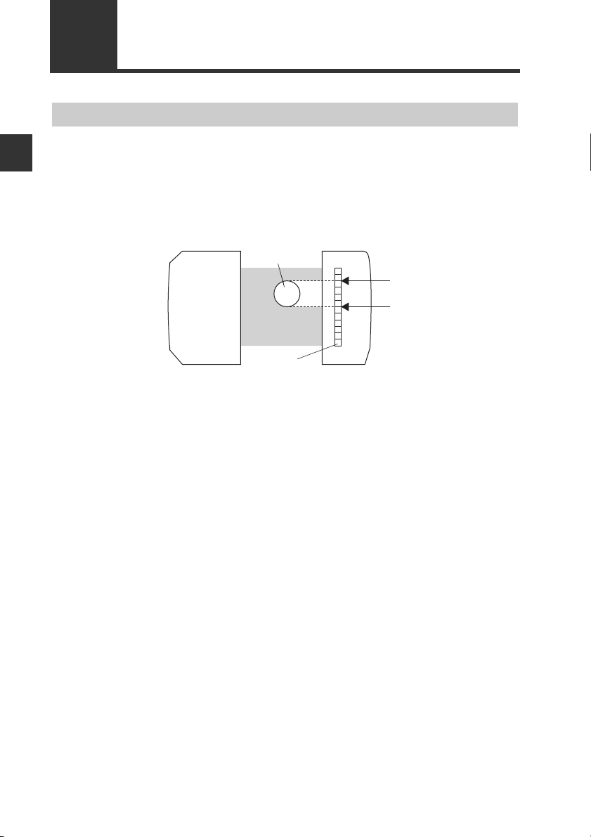
Measurement Principle
This unit receives laser light from the transmitter. The receiver uses a CCD (Charge
Coupled Device) as the receiving detector. The CCD is a linear array of light receiving
elements. When a target is placed between the transmitter and receiver, a shadow is
caused on the receiver. By detecting the light to dark and dark to light transitions, the unit is
able to measure those areas accurately.
For details, refer to "4-3 Setting the Measurement Sensitivity" (page 4-44).
Transmitter Receiver
Object
CCD
Edge
Edge
1-2
IG-E
Page 13
1-1 Overview of the IG Series
Light-shielding object
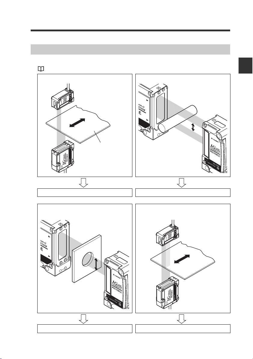
Specialized Measurement Modes
You can select a suitable measurement mode according to the particular application.
"1. Measurement mode" (page 4-8)
Edge control/Positioning Outer diameter/Width measurement
A. Edge control/Positioning mode B. Outer diameter/Width measurement mode
1
Before Use
IG-E
Inner diameter Transparent object Edge control/
Positioning
C. Inner diameter D. Glass edge mode
1-3
Page 14
1-1 Overview of the IG Series
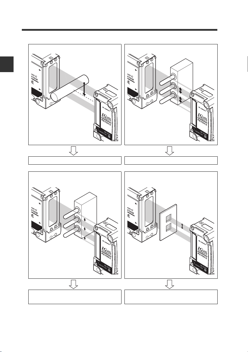
Center position measurement Pitch measurement
1
Before Use
E. Pin position measurement mode F. Pin interval judgment mode
1-4
Multiple diameter measurement Measure the distance between
G. Pin diameter judgment mode
specified edges.
H. Specified edges interval
measurement mode
IG-E
Page 15
1-1 Overview of the IG Series
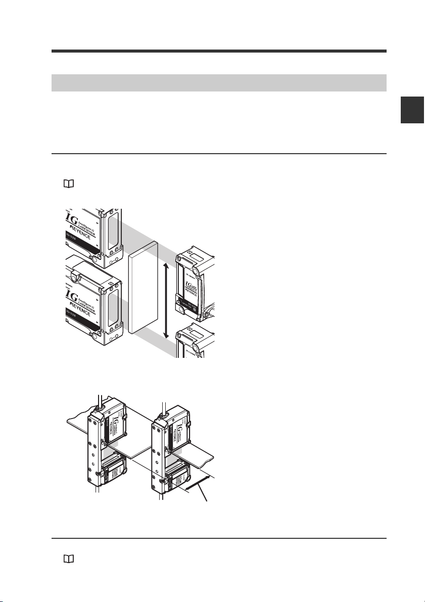
Level to be measured
Using the Expansion Units
The IG Series include main units (IG-1000, IG-1500) and expansion units (IG-1050, IG-
1550). By connecting the expansion unit to the main unit, the IG Series can be used for
various purposes.
Calculation function
To le r ance is judged based on the calculated result (calculated value) of measurement value
of two units of IG Series and the analog output can be performed.
"4-4 Calculation Function" (page 4-47)
Adding the measurement value
The diameter or width of a target that
cannot be measured with one unit can be
measured.
1
Before Use
Subtracting the measurement value
The level of a target can be calculated.
Interference prevention function
Mutual interference can be prevented between the additionally installed IG Series units.
"14. Interference prevention function (only for IG-1000/1500)" (page 4-40)
IG-E
1-5
Page 16
1
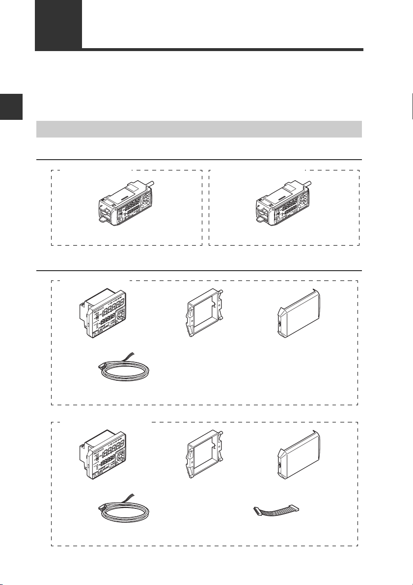
Sensor amplifier x 1
Instruction manual x 1
Sensor amplifier x 1
IG-1000 (main unit) IG-1050 (expansion unit)
IG-1500 (main unit)
Sensor amplifier x 1 Panel mounting
tool x 1
Front protection
cover x 1
Power/Input-output cable (2 m) x 1
(12 cores)
Instruction manual x 1
IG-1550 (expansion unit)
Sensor amplifier x 1 Panel mounting
tool x 1
Front protection
cover x 1
Input-output cable (2 m) x 1
(8 cores)
1-2 Checking the Package Contents
The following equipment and accessories are included in the package. Before using the
unit, make sure that all items are included.
We have thoroughly inspected the package contents before shipment. However, in the
event of defective or broken items, contact your nearest KEYENCE office.
Sensor Amplifier
Before Use
DIN rail mount type
Panel mount type
1-6
Expansion cable
(50mm) x 1
IG-E
Page 17
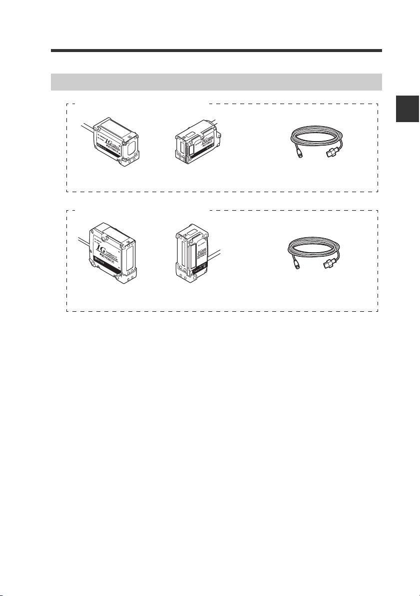
Sensor Head
IG-010 (Measurement range: 10 mm)
Transmitter x 1 Receiver x 1 Sensor head connection cable (2 m)
x 2
IG-028 (Measurement range: 28 mm)
Transmitter x 1 Receiver x 1 Sensor head connection cable (2 m)
x 2
1-2 Checking the Package Contents
1
Before Use
IG-E
1-7
Page 18
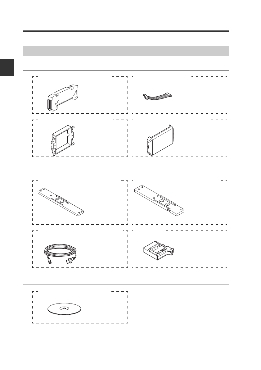
1-2 Checking the Package Contents
End unit
x 2
Expansion cable
(300 mm) x 1
OP-26751 (For IG-1000/IG-1050) OP-35361 (For IG-1550)
Panel mounting
tool x 1
Front protection
cover x 1
OP-4122 (For IG-1500/IG-1550) OP-87076 (For IG-1500/IG-1550)
Hexagon socket
head bolt x 6
(M3 x 5 mm, with
washer)
Hexagon socket
head bolt x 7
(M3 x 5 mm, with
washer)
IG-TB01 (Mounting bracket for the IG-010)
IG-TB02 (Mounting bracket for the IG-028)
Mounting bracket x 1 Mounting bracket x 1
Sensor head
connection
cable x 1
Sensor head
cable connector
x 2
OP-87056 (2 m)/OP-87057(5 m)/
OP-87058 (10 m)/OP-87059 (20 m)
OP-84338
x 1
IG Configuration Software (IG-H1)
List of Optional Parts
1
Before Use
For Sensor amplifier
For Sensor head
Others
To use the IG configuration software (IG Configurator), "RS-232C Communication Unit DLRS1A" is required. For details on DL-RS1A, refer to "RS-232C Communication Unit DLRS1A User’s Manual".
1-8
IG-E
Page 19
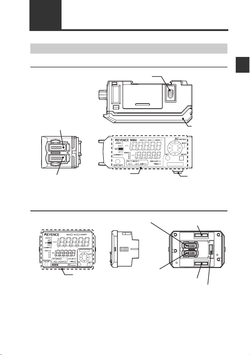
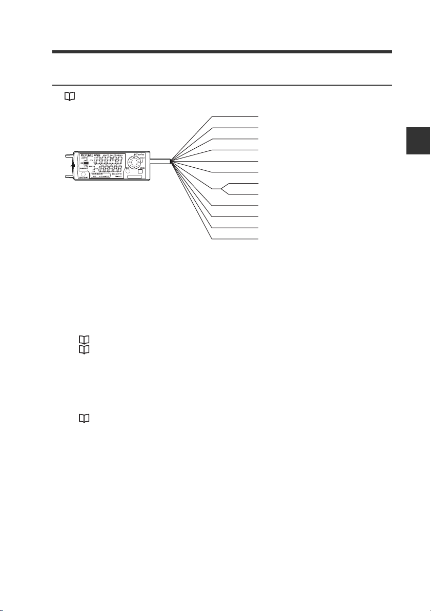
1-3 Part Names and Functions
Expansion unit connector*
1
Amplifier control
unit cover
Sensor head connector (Transmitter side)
Amplifier control unit
Sensor head connector (Receiver side)
Expansion unit
connector*
2
Power/Input-output
cable connector
Expansion unit connector
(upper)*
1
Expansion unit connector (lower)*
2
Sensor head connector (Transmitter side)
Sensor head connector (Receiver side)
Amplifier control unit
Sensor Amplifier Unit
DIN rail mount type (IG-1000/IG-1050)
*1 When shipped from the factory, the protective cover for expansion slots is installed.
*2 It is not installed on the main unit (IG-1000).
Panel mount type (IG-1500/IG-1550)
1
Before Use
*1 It is not installed on the main unit (IG-1500).
*2 When shipped from the factory, the protective seal is attached.
IG-E
1-9
Page 20
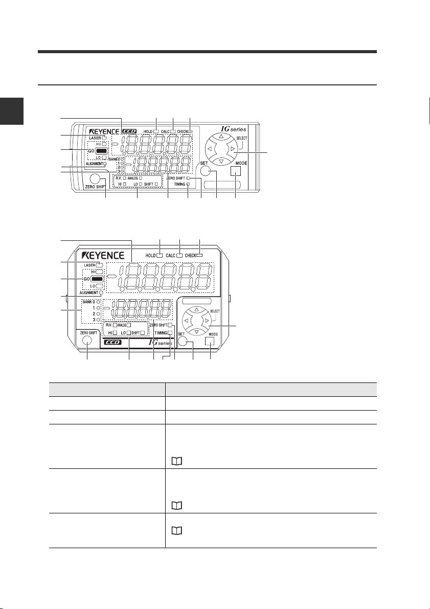
1-3 Part Names and Functions
(11) (12)(10)(6)
(16) (15) (14)
(1)
(2)
(3)
(4)
(5)
(7) (8) (9)
(13)
(11) (12)(10)(6)
(16) (15) (14)
(1)
(2)
(3)
(4)
(5)
(7) (8)(9)
(13)
Amplifier control unit
DIN rail mount type (IG-1000/IG-1050)
1
Before Use
Panel mount type (IG-1500/IG-1550)
Item Description
(1) Main displayDisplays the judgment value (P.V.) and each setting item.
(2) Laser emission indicator Lights on while the laser beams are emitted.
Displays whether the judgment value (P.V.) is HIGH (over
(3) judgment indicator
Optical axis alignment
(4)
indicator
(5) Bank indicator
the upper limit), GO (within the acceptable range) or LOW
(below the lower limit) against the tolerance setting value.
"3-6 Setting the Tolerance Setting Value" (page 3-11)
Lights up when the optical axis is successfully aligned.
Align the optical axis when the target is not present and the
optical alignment indicator is off.
"3-3 Optical Axis Alignment" (page 3-8)
Displays a bank in use.
"3-8 Bank Function (Registering Multiple Tolerance
Setting Values)" (page 3-18)
1-10
IG-E
Page 21
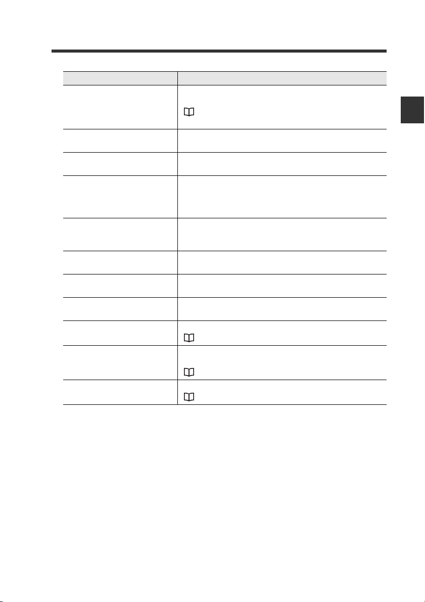
Item Description
(6) Zero shift button
(7) Sub display indicator
(8) Sub display
(9) Timing input indicator
(10) Zero shift indicator
(11) SET button
(12) MODE button
(13) Arrow button
(14) Check indicator
(15) Calculation indicator
(16) Hold indicator
1-3 Part Names and Functions
Press this button to match the internal measurement value
(R.V.) to the shift target value.
"3-7 Zero Shift Function (Shifting the Internal
Measurement Value (R.V.))" (page 3-16)
Lights up according to the type of values displayed on the
sub display.
Displays the internal measurement value (R.V.), analog
output value and each setting (selection) item.
Lights up while the timing input is ON when the timing input
(external input) is set to Level. Lights on approx. 0.5 sec.
when the timing input is set to Edge and the timing input is
turned ON.
Lights up approx. 0.5 sec. when the zero shift button is
pressed and released, or the zero shift input (external
input) is turned ON.
Used to automatically adjust the setting values when
setting each item.
Used when setting each item, starting/ending the setting or
moving items.
Used when selecting setting items, changing display
contents on the sub display, etc.
Lights up when the edge check output is ON.
"9. Edge check function" (page 4-31)
Lights up when calculation is in process using the
calculation function.
"4-4 Calculation Function" (page 4-47)
Lights up when the judgment value (P.V.) is held.
"5. Hold function" (page 4-20)
1
Before Use
IG-E
1-11
Page 22
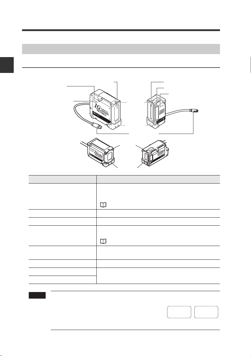
1-3 Part Names and Functions
Note
(1) Optical axis
alignment indicator
[ALIGNMENT]
(4) Optical axis
alignment indicator
[ALIGNMENT]
(2) Power indicator
[POWER]
(5) Position Monitor
(7) Laser transmitter
(6) Laser receiver
(3) Connector
Transmitter Receiver
(8) Top
(9) Bottom
Sensor Head Unit
1
Before Use
IG-028/IG-010
(8) Top
(9) Bottom
Item Description
Lights up when the optical axis is successfully aligned.
(1)
Optical axis alignment
(4)
indicator
(2) Power indicator Lights on when the power is supplied to the sensor head.
(3) Connector Connect with the sensor head connection cable.
(5) Position monitor
(6) Laser receiver
(7) Laser transmitter Emits laser beams. The surface is covered with the glass.
(8) Top
(9) Bottom
Align the optical axis when the target is not present and the
optical alignment indicator is off.
"3-3 Optical Axis Alignment" (page 3-8)
Used to check the laser light-receiving status, measured
parts, etc.
"17. Position monitor" (page 4-41)
Receives laser beams. The surface is covered with the
glass.
Distinguishing between top and bottom is important when
installing the sensor head or measuring.
1-12
Use the transmitter and receiver in combination
of the same serial number. If they are used in
combination of the different serial numbers, the
operation and accuracy are not guaranteed. The
serial number is attached on top of the
transmitter and receiver.
Transmitter
SERIAL No.
12345678
Receiver
No.
12345678
IG-E
Page 23

Installation and Connection2
This chapter describes precautions when installing and connecting
the IG Series.
2-1 Mounting and Wiring the Sensor Amplifier ........ 2-2
2-2 Connecting and Mounting the Sensor Head....... 2-8
2
IG-E
2-1
Page 24
2
CAUTION
Note
Installation and Connection
2-1
Mounting and Wiring the Sensor Amplifier
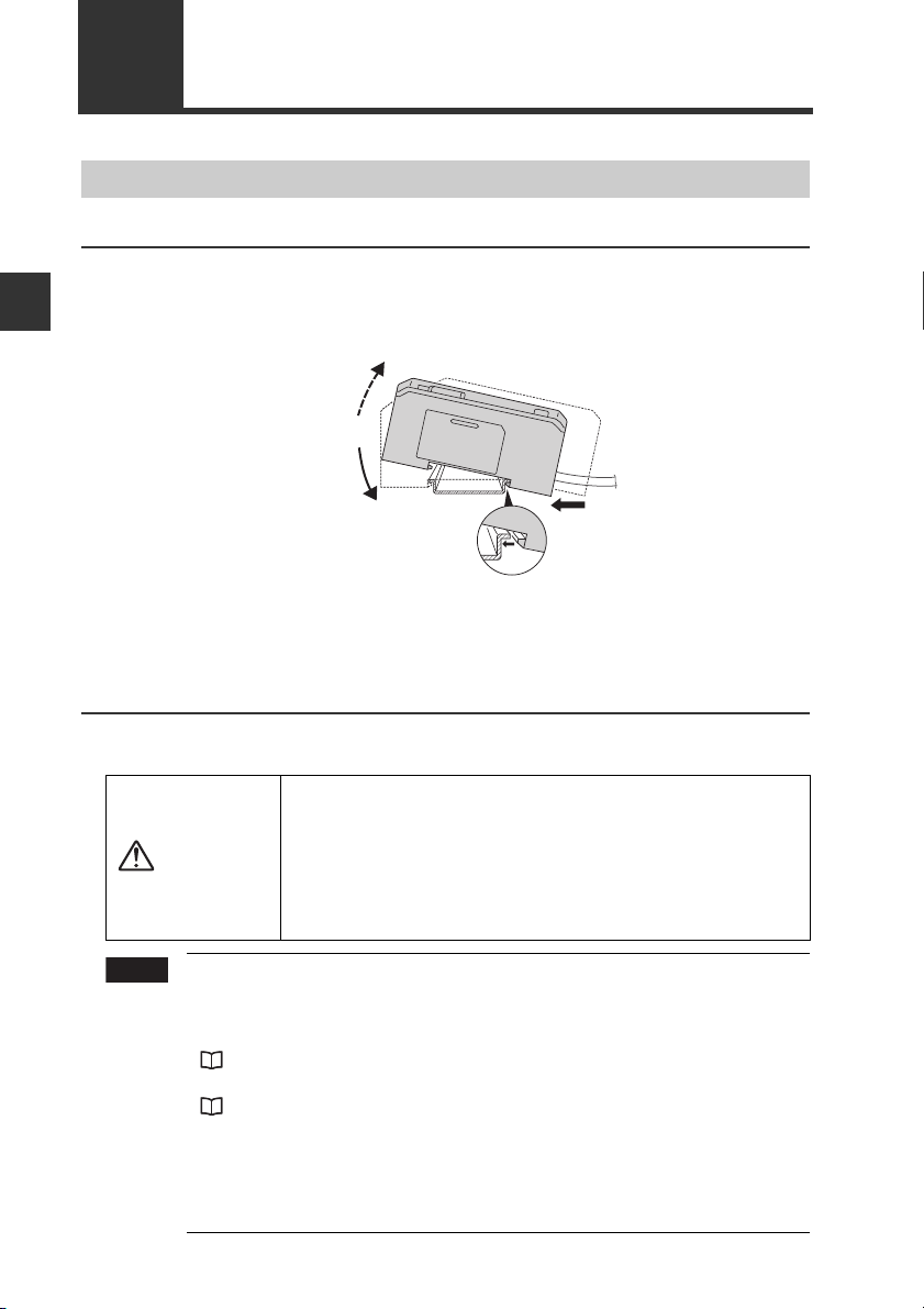
Mounting the Sensor Amplifier
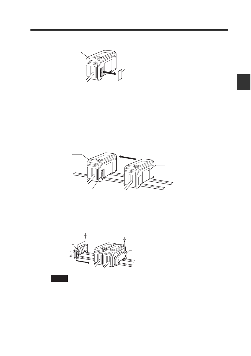
DIN rail mount type, main unit (IG-1000)
Align the claw at the bottom of the main body with the DIN rail. While
1
pushing the main body in the direction of the arrow (1), slant it in the
direction of the arrow (2).
(3)
(2)
To dismount the sensor, raise the main body in the direction of the arrow
2
(3) while pushing the main body in the direction of the arrow (1).
DIN rail mount type, expansion unit (IG-1050)
Several expansion units can be used in connection with the main unit.
Up to 3 expansion units can be connected to one main unit.
• When connecting multiple amplifiers (expansion units),
first check to make sure that the power is turned OFF to all
of the main and expansion units. Connecting the units
with the power turned ON may cause damage to the units.
•Push the amplifiers (expansion units) as close as possible
the main unit. Improper connections may damage the
equipment.
• When connecting the expansion units, make sure to initialize the
connected expansion units and set the output polarity.
(1) When turning on the amplifier for the first time after connecting the
sensor head
"3-1 Operation When the Power is Turned on for the First Time" (page 3-2)
(2) When performing the initial reset
"3-5 Initial Reset (Initialize)" (page 3-10)
• Expansion units with different setting of output polarity (such as an
NPN output expansion unit to a PNP output main unit) cannot be
connected together.
• Expansion units of DIN rail mount type cannot be connected to the
main unit of panel mount type.
(1)
2-2
IG-E
Page 25
2-1 Mounting and Wiring the Sensor Amplifier
Remove the expansion protective cover from the IG-1000 (main unit).
1
Main unit
Connector cover
Install the amplifiers (expansion units) on the DIN rail.
2
Refer to "DIN rail mount type (Main unit)" for details about how to mount.
Push the expansion unit into the main unit connector until a clicking
3
sound can be heard.
The expansion unit additionally installed next to the main unit is referred to as
expansion unit 1. Subsequent expansion units are referred to as expansion unit 2,
expansion unit 3, etc.
Main unit
Expansion unit 1
Connecter
2
Installation and Connection
IG-E
Install the end units (OP-26751: 2 units in a set) (sold separately) on both
4
sides of the amplifiers (main and expansion units). Secure the end units in
place with screws on top (2 on each end unit).
The end units are mounted in the same way as the amplifiers.
End unit
End unit
Note
Fix the amplifiers securely using the end units (OP-26751: 2 units
in a set) (sold separately) or commercially available DIN rail fixing
tool to prevent the amplifiers from slipping the DIN rail or coming
off from the DIN rail due to machine vibration.
2-3
Page 26
2-1 Mounting and Wiring the Sensor Amplifier
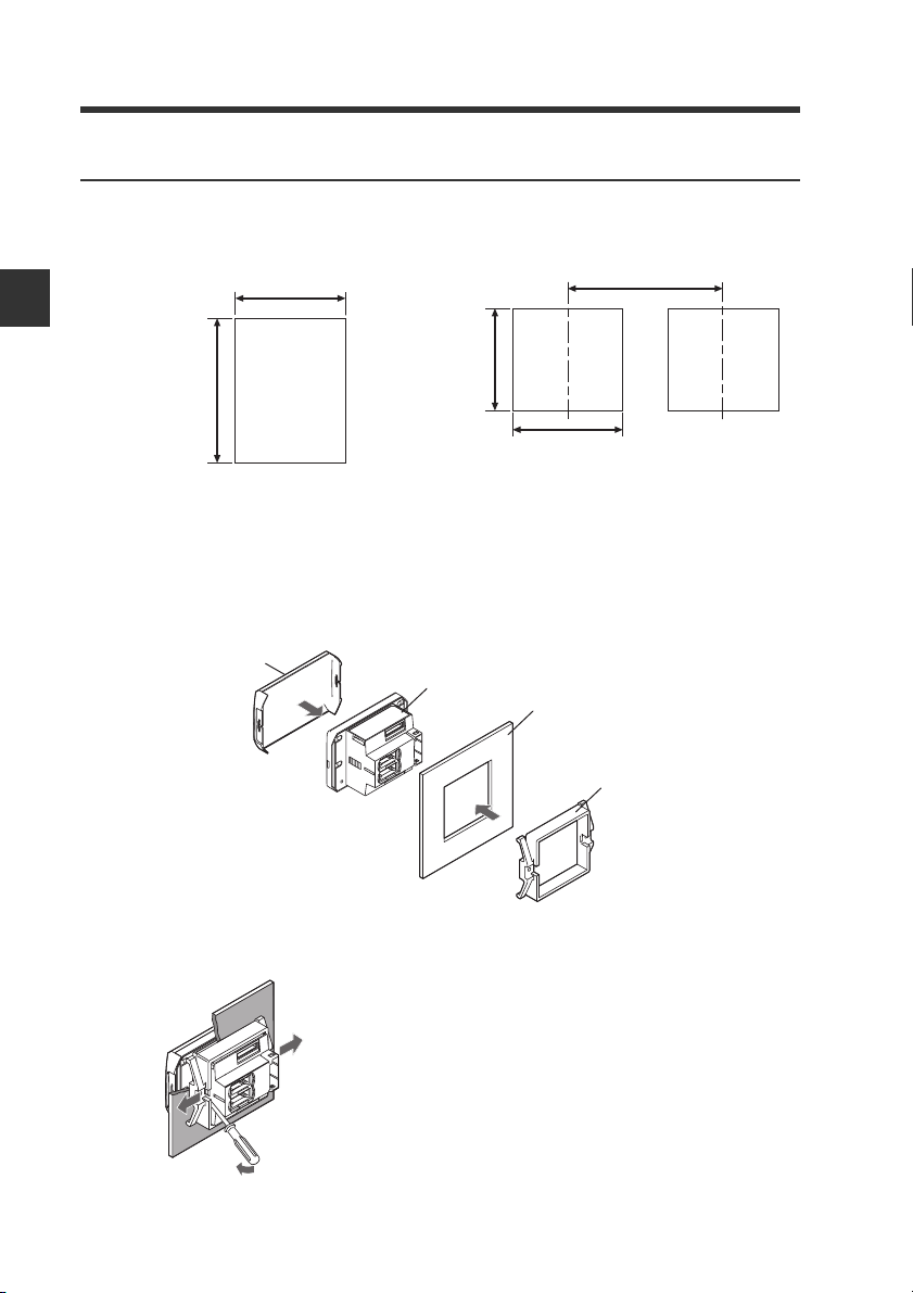
Min. 85mm
45mm
45mm
+ 0.6
− 0
+ 0.6
− 0
Panel mount type, main unit (IG-1500)
Make a hole on the panel to attach according to the size below.
1
When arranging lengthwise to attach When arranging widthwise to attach
+ 0.6
45mm
− 0
2
Installation and Connection
X mm
•Panel thickness 1 to 6 mm
• X=48 x (number of amplifiers) -3
Insert the back side of amplifier to the hole of panel.
2
Arrange the panel mounting tool in the direction below, fix to the amplifier
3
from the back and attach the front protection cover to the amplifier.
Front protection cover
Sensor amplifier
Panel
2-4
Panel mounting tool
To remove the panel mounting tool, widen the claws at both ends of the panel
mounting tool using a slotted screwdriver, etc. and remove alternately.
IG-E
Page 27
2-1 Mounting and Wiring the Sensor Amplifier
CAUTION
Panel mount type, expansion unit (IG-1550)
Several expansion units can be used in connection with the main unit. Up to 3 expansion
units can be connected to one main unit.
• Turn OFF the power before connecting the expansion
cable. Inserting or removing the cable with the power
turned on may cause damage to the units.
•Be sure to completely connect the expansion cable.
Improper connections may damage the equipment.
2
Installation and Connection
Note
1
2
3
• When connecting the expansion units, make sure to initialize the
connected expansion units and set the output polarity.
When turning on the amplifier for the first time after connecting the sensor head
(1)
"3-1 Operation When the Power is Turned on for the First Time" (page 3-2)
(2) When performing the initial reset
"3-5 Initial Reset (Initialize)" (page 3-10)
•
Expansion units with different setting of output polarity (such as an NPN output
expansion unit to a PNP output main unit) cannot be connected together.
•Expansion units of panel mount type cannot be connected to the
main unit of DIN rail mount type.
Make holes on the panel to attach according to the number of amplifiers
(connected expansion units).
For the panel cutting size, refer to the "Panel mount type, main unit".
Install the amplifiers (expansion units) on the panel.
For the amplifier mounting method, refer to the "Panel mount type, main unit".
Connect the amplifier (main unit) and amplifier (expansion unit) using the
expansion cable (50 mm) supplied with the expansion unit.
The expansion unit additionally installed next to the main unit is referred to as
expansion unit 1. Subsequent expansion units are referred to as expansion unit 2,
expansion unit 3, etc.
Main unit
IG-E
Reference
Expansion cable
Expansion unit 1
When arranging the amplifiers side by side, the expansion cable of 300 mm
(OP-35361) is necessary.
2-5
Page 28
2-1 Mounting and Wiring the Sensor Amplifier
Note
Power/Input-output cable
To attach To remove
Sensor Amplifier Wiring
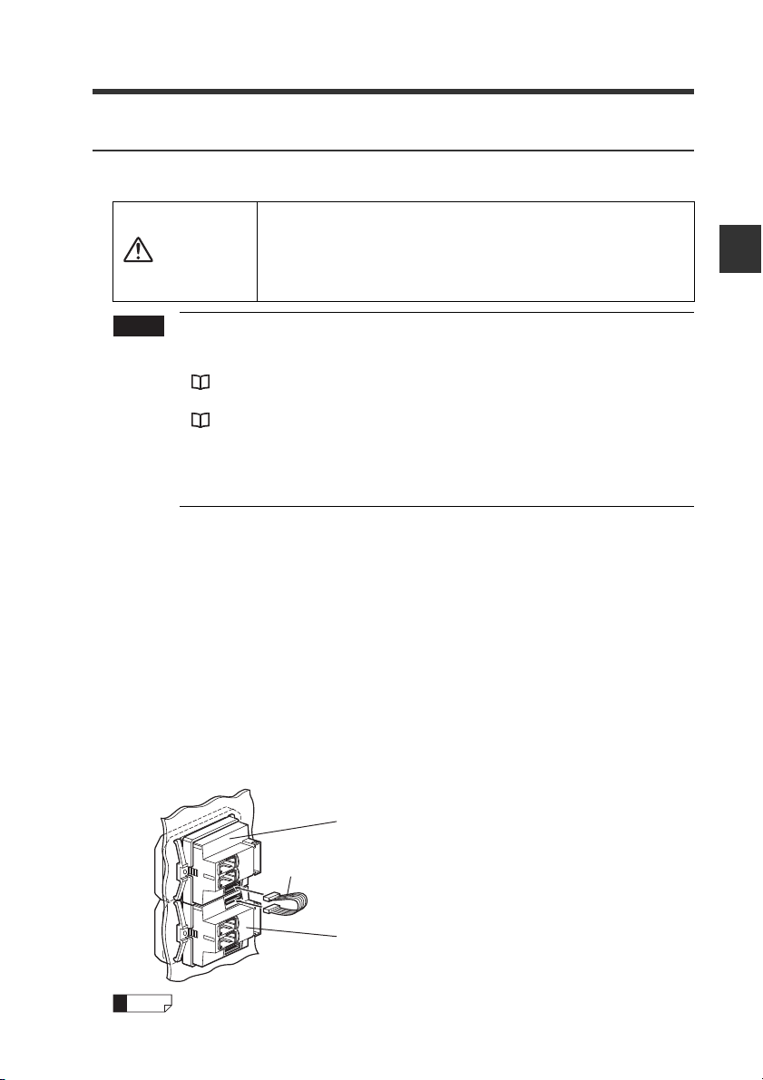
Connecting power/Input-output cable (only for panel mount type)
Connect the power/input-output cable to the panel mount type main unit and connect the
input-output cable to the expansion units.
2
Installation and Connection
• The number of core wire of power/input-output cable for the main unit
is 12, and the number of core wire of Input-output cable for the
expansion units is 8.
• Power for the expansion units is supplied from the main unit.
• If the input-output is not used for the expansion units, cut the cable at
the connector base or terminate the wires properly for future use.
2-6
IG-E
Page 29
2-1 Mounting and Wiring the Sensor Amplifier
Brown
Blue
Black
White
Gray
Light blue
Orange
Shield
Pink
Yellow
Pink/Purple
Purple
Green
10 to 30 VDC
0 V
HIGH judgment output
LOW judgment output
GO judgment output
Analog output +
Analog output GND
External input 1 (Zero shift input)
External input 2 (Reset input)
External input 3 (Timing input)
External Input 4 (Gain input)
Edge check output
*1
*1
*1
*2
*2
*3
*3
*3
*3
Power/Input-output cable
"Output Circuit Diagram" (page 5-4)
*1 IG-1050/IG-1550 (expansion units) do not have brown, blue or light blue wires.
Power is supplied to the expansion units through IG-1000/IG-1500 (main unit).
*2 The analog output can be set to either "When the power is turned on for the first time"
or "When performing the initial reset".
• Not used (OFF)
• 0 to 5 V
• -5 to 5 V
• 1 to 5 V
• 4 to 20 mA
"3-1 Operation When the Power is Turned on for the First Time" (page 3-2)
"3-5 Initial Reset (Initialize)" (page 3-10)
*3 The external input can be selected among the following in addition to the above.
• Bank A input
• Bank B input
• Laser emission stop input
• Not used (OFF)
Gain input can be selected only for the external input 4.
"11. External input" (page 4-33)
2
Installation and Connection
IG-E
2-7
Page 30
2
Note
Transmitter Receiver
Transmitter Receiver
Mounting distance
A
B
Installation and Connection
2-2
Connecting and Mounting the Sensor Head
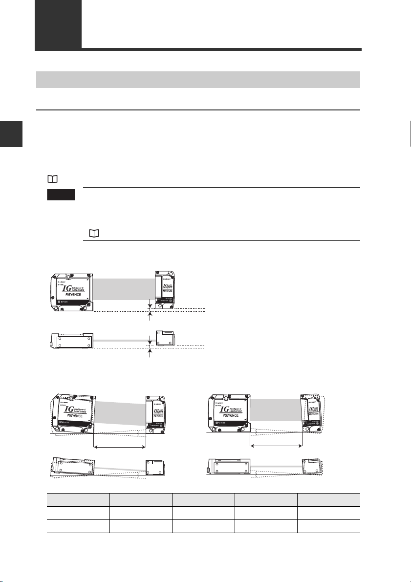
Mounting the Sensor Head
Notes for mounting
If the mounting distance between the transmitter and receiver is as follows, the optical axis
alignment is not necessary when mounting within the "parallel acceptable range" and "tilt
acceptable range".
• IG-010 : 3 to 500 mm
• IG-028 : 50 to 500 mm
If the distance is beyond the above ranges, align the optical axis after mounting.
"3-3 Optical Axis Alignment" (page 3-8)
The minimum object for detection, linearity and temperature
characteristics in the specifications are values when mounting the
sensor head within the "parallel acceptable range" and "tilt acceptable
range".
"5-1 Specifications" (page 5-2)
Parallel acceptable range
Transmitter Receiver
Transmitter Receiver
Tilt acceptable range
Tilt of transmitter Tilt of receiver
Mounting distance
500 mm or less within ±0.05° within ±0.05° within ±1° within ±2°
100 mm or less within ±0.2° within ±0.2° within ±1° within ±2°
within ±0.5 mm
within ±0.5 mm
2-8
Transmitter Receiver
Transmitter Receiver
A B C D
C
Mounting distance
D
IG-E
Page 31

2-2 Connecting and Mounting the Sensor Head
Transmitter Receiver
Received waveform image of CCD
Object
Mounting distance and insertion position of a target
Measurement accuracy changes depending on the mounting distance between the
transmitter and receiver of the sensor head and insertion position of the object.
"5-1 Specifications" (page 5-2)
When the mounting distance is long and the object is far from the receiver, the light
diffraction caused by the object increases. Because of this, the edge of CCD’s lightreceiving waveform generated by the object is skewed increasing measurement error.
To i n cr ease the measurement accuracy, make the mounting distance as short as possible
and move the insertion position of the object closer to the receiver.
When the mounting distance is shor
When the mounting distance is long and
Transmitter Receiver
t and the object is close to the receiver
the object is far from the receiver
Object
Received waveform image of CCD
2
Installation and Connection
IG-E
2-9
Page 32

2-2 Connecting and Mounting the Sensor Head
Mounting from the side
Mounting from the sensor side
Fix using the commercially available screws (IG-010: M3, IG-028: M4).
Tightening torque: 1.6 N·m or less
IG-010 IG-028
2
Installation and Connection
Mounting from the jig side
Fix using the commercially available screws (IG-010: M4, IG-028: M5, length: board
thickness + 5 mm or less).
Tightening torque: 1.6 N·m or less
IG-010 IG-028
2-10
IG-E
Page 33

2-2 Connecting and Mounting the Sensor Head
Mounting from the bottom
Fix using the commercially available screws.
IG-010: M3, board thickness +4 mm or less
IG-028: M3, board thickness +5 mm or less
Tightening torque: 1.6 N·m or less
IG-010 IG-028
When the mounting bracket (IG-TB01/IG-TB02) is used
Attach the mounting bracket to the sensor head.
1
Press the sensor head to the mounting bracket firmly and fix with the included
hexagon socket head bolt (M3, length: 5 mm).
Tightening torque: 1.6 N·m or less
IG-010 IG-028
2
Installation and Connection
IG-E
Note
Fix through the mounting holes from the upper part of the mounting bracket.
2
Use the commercially available hexagon socket head bolt (M4) to fix the mounting
bracket through its holes.
IG-010 IG-028
Press the sensor head to the mounting
bracket firmly and fix.
2-11
Page 34

2-2 Connecting and Mounting the Sensor Head
Note
The red O-ring is attached to the transmission cable and
blue O-ring to the receiver cable. Connect the sensor head
connection cable with red O-ring to the transmitter and
connect the sensor head connection cable with blue O-ring
to the receiver.
Down: R side
Blue O-ring
Right: R side
Sensor Head Connection
Connecting the sensor head and sensor amplifier
Connect the sensor head connection cable to the transmitter and receiver
2
Installation and Connection
1
cables respectively.
(1) Align the arrow position of the connector to insert.
(2) Rotate the connector screw to tighten.
Tighten the connectors securely with hand. If loosely tightened,
the environment resistance IP67 cannot be guaranteed.
Connect the sensor head connection cable on the receiver side to the [R]
2
connector of amplifier.
Remove the lock cover of the connector and
insert it to the connector (R) of amplifier until a
clicking sound can be heard.
Lock cover
Click
Unlocked
2-12
DIN rail mount type
(IG-1000/IG-1050)
Panel mount type
(IG-1500/IG-1550)
IG-E
Page 35

2-2 Connecting and Mounting the Sensor Head
Lock lever
Top: T side
Red O-ring
Left: T side
Attach the lock cover to the connector to fix the cable.
3
Lock cover
Locked
2
Note
Connect the sensor head connection cable on the transmitter side to the
4
[T] connector of amplifier.
DIN rail mount type
(IG-1000/IG-1050)
The connection procedure is the same as the one for the receiver.
When removing the sensor head connection cable, push the lock
lever and pull it out.
Panel mount type
(IG-1500/IG-1550)
Installation and Connection
IG-E
2-13
Page 36

2-2 Connecting and Mounting the Sensor Head
Note
Note
Blue
White
Black
Brown
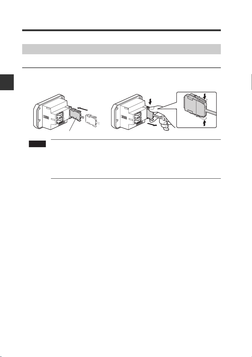
Attaching the sensor head cable connector (OP-84338)
Cut the sensor head connection cable to the required length and attach the new connector
to use the sensor. The attaching method is the same for both transmitter and receiver.
Cut the cable to the required length and strip approx. 15 mm of insulation
1
from the end of the cable.
2
Installation and Connection
Do not strip the core wire insulation.
Insert each cable to the end matching to the same color marks on the
2
connector.
The cables are inserted to the end and tentatively fixed.
Insert further
than here.
2-14
Confirm that all cables are inserted to the specified position and crimp
3
them tight parallel using a plier or similar tool.
If the connector is changed, make sure to connect it to the
amplifier and confirm the normal operation.
If it does not operate normally, crimp the connector again with a
plier.
Once the connector is crimped, it cannot be reused.
IG-E
Page 37

Basic Operations3
This chapter describes basic operations and settings for the IG
Series.
Operation When the Power is Turned on for the First Time
3-1
3-2 Operations on the Main Screens ......................... 3-3
3-3 Optical Axis Alignment ......................................... 3-8
3-4
Registering the Standard Waveform (Gain adjustment)
3-5 Initial Reset (Initialize) ........................................ 3-10
3-6 Setting the Tolerance Setting Value .................. 3-11
3-7
Zero Shift Function (Shifting the Internal Measurement Value (R.V.))
3-8
Bank Function (Registering Multiple Tolerance Setting Values)
3-9 Key Lock Function .............................................. 3-21
3-10 Selecting the Display Unit .................................. 3-22
....... 3-2
...... 3-9
.... 3-16
.... 3-18
3
IG-E
3-1
Page 38

3
Note
GPF
Setting value
Description
PRP
NPN output
RPR
PNP output
QHH
LASER
BANK
0
1
2
3
HI
LO
R.V.
ANALOG
HI SHIFT
ZERO SHIFT
TIMING
LO
ALIGNMENT
#P.)
GO
HOLD CALC
CHECK
Analog output
Setting value
Description
QHH
Not output
W
Analog output after the judgment value (P.V.) is converted
to the range from 0 to 5 V.
W
Analog output after the judgment value (P.V.) is converted
to the range from -5 to 5 V.
W
Analog output after the judgment value (P.V.) is converted
to the range from 1 to 5 V.
CORT
Analog output after the judgment value (P.V.) is converted to
the range from 4 to 20 mA.
3-1
Operation When the Power is Turned on for the First Time
When the amplifier is turned on for the first time after the sensor head is connected, the
initial setting screen appears after a few seconds. Make the initial settings according to the
following procedure.
The initial setting is necessary for both the main unit and the expansion units when units
are added.
The initial setting screen appears only when the power is turned on for
the first time. It will not appear when the power is turned on again. To
change these settings, perform the initial reset.
"3-5 Initial Reset (Initialize)" (page 3-10)
Basic Operations
Power ON
LASER
HI
GO
LO
BANK
0
1
ALIGNMENT
2
3
ANALOG
R.V.
HI SHIFT
LO
Output polarity
HOLD CALC
QWV
PRP
ZERO SHIFT
TIMING
CHECK
Press S / T button to select the polarity of judgment
1
output and edge check output, and then press [MODE]
button.
[MODE] button
Press S / T button to select the type of analog output
2
and press [MODE] button.
3-2
[MODE] button
"10. Analog output scaling" (page 4-32)
HOLD CALC
CHECK
0
1
2
'PF
3
ZERO SHIFT
ANALOG
R.V.
HI SHIFT
LO
TIMING
Perform "3-3 Optical Axis Alignment" (page 3-8) and "3-4 Registering the
Standard Waveform (Gain adjustment)" (page 3-9).
4
LASER
GO
ALIGNMENT
HI
LO
BANK
After the setting is complete, [
3
times on the sub display and the main screen
appears.
] blinks several
Make other settings as necessary.
IG-E
Page 39

3-2 Operations on the Main Screens
LASER
BANK
0
1
2
3
HI
GO
LO
R.V.
ANALOG
HI SHIFT
ZERO SHIFT
TIMING
LO
ALIGNMENT
HOLD CALC
CHECK
R.V. (Internal Measurement Value) and P.V. (Judgment Value)
This section describes R.V. (Internal Measurement Value) displayed on the sub display
(lower level) and P.V. (Judgment Value) displayed on the main display (upper level).
R.V. (Internal Measurement Value)
R.V. (Internal Measurement Value) is the value displayed when a target is inserted into the
measurement range.
* R.V. = Raw Value
P.V. ( Ju dg m e nt Va l ue )
P. V. ( J udgment Value) is the value to
tolera
nce setting value. Also, the analog output is output based on the P.V..
* P.V. = Present Value
"3-6 Setting the Tolerance Setting Value" (page 3-11)
The judgment value (P.V.) and the internal measurement value (R.V.) are basically the
same, however, those values differ only when the hold function and calculation function are
used.
"5. Hold function" (page 4-20)
"4-4 Calculation Function" (page 4-47)
Main Display (Upper Level)
The judgment value (P.V.) is displayed on the main display.
The display varies as below according to each function to be used such as Normal, Hold
function, Calculation function.
Normal
The same value as the internal measurement value (R.V.) is displayed
as a judgment value (P.V.).
[HOLD] ON
LASER
HI
GO
LO
BANK
0
1
ALIGNMENT
2
3
R.V.
HI SHIFT
[CALC] ON
LASER
HI
GO
LO
BANK
0
1
ALIGNMENT
2
3
R.V.
HI SHIFT
HOLD CALC
ANALOG
LO
HOLD CALC
ANALOG
LO
When the hold function is used
CHECK
The judgment value (P.V.) is held according to the hold function settings.
"5. Hold function" (page 4-20)
ZERO SHIFT
TIMING
When the calculation function is used
CHECK
Main unit:
Expansion unit: The same display as for Normal
ZERO SHIFT
TIMING
"4-4 Calculation Function" (page 4-47)
set the judgment output to ON/OFF according to the
Displays the calculated result (calculation value) with the
calculation function as a judgment value (P.V.).
3
Basic Operations
IG-E
Reference
When both the hold function and calculation function are used, the hold
indicator [HOLD] and calculation indicator [CALC] light up. The judgment value
(P.V.) on the main display is displayed as below.
Main unit: Displays the calculation value (CALC value) as a judgment
value (P.V.). Held according to the hold function setting.
Expansion unit: Th
e same display as for Normal. Held according to t
he hold
function setting.
3-3
Page 40

3-2 Operations on the Main Screens
GO
HOLD CALC
CHECK
LASER
BANK
0
1
2
3
HI
LO
R.V.
ANALOG
HI SHIFT
ZERO SHIFT
TIMING
LO
ALIGNMENT
LOW side setting value
[LO]
ON
GO
LASER
BANK
0
1
2
3
HI
LO
R.V.
ANALOG
HI SHIFT
ZERO SHIFT
TIMING
LO
ALIGNMENT
HOLD CALC
CHECK
[HI]
ON
HIGH side setting value
GO
HOLD CALC
CHECK
LASER
BANK
0
1
2
3
HI
LO
R.V.
ANALOG
HI SHIFT
ZERO SHIFT
TIMING
LO
ALIGNMENT
Shift target value
[SHIFT]
ON
LASER
BANK
0
1
2
3
HI
LO
R.V.
ANALOG
HI SHIFT
ZERO SHIFT
TIMING
LO
ALIGNMENT
HOLD CALC
CHECK
GO
All
OFF
[
%#.E
] is displayed
only once.
LASER
BANK
0
1
2
3
HI
LO
R.V.
ANALOG
HI SHIFT
ZERO SHIFT
TIMING
LO
ALIGNMENT
HOLD CALC
CHECK
GO
R.V.
[R.V.]
ON
W
LASER
BANK
0
1
2
3
HI
LO
R.V.
ANALOG
HI SHIFT
ZERO SHIFT
TIMING
LO
ALIGNMENT
HOLD CALC
CHECK
GO
Analog output
[ANALOG]
ON
(1) R.V. display screen
(6) Calculated value display screen
*Displayed only for the main
unit and when the calculation
function is used.
*Displayed only for the
main unit and when the
analog output is used.
(2) Analog output screen
(5) Shift target value setting screen
(3) HIGH side setting value screen
(4) LOW side setting value screen
Sub Display (Lower Level)
The sub display can be switched with the arrow buttons W / X.
According to the type of displayed value, the sub display indicator [R.V. / ANALOG / HI / LO
/ SHIFT] lights up.
3
Basic Operations
3-4
IG-E
Page 41

3-2 Operations on the Main Screens
(1) R.V. display screen
The internal measurement value (R.V.) is displayed. The displayed value is not held.
Reference
(2)Analog output screen (displayed only for the main unit and when the analog
output is used)
The voltage value (unit: V) or current value (unit: mA) of the analog output is displayed.
(3) HIGH side setting value screen
The upper limit of the acceptable range (tolerance setting value) for the object is
displayed. Also, the setting value can be changed. If the judgment value (P.V.) exceeds
the value set here, the HIGH judgment output turns on.
(4) LOW side setting value screen
The lower limit of the acceptable range (tolerance setting value) for the object is
displayed. Also, the setting value can be changed. If the judgment value (P.V.) falls
below the value set here, the LOW judgment output turns on.
(5) Shift target value screen
When the zero shift button is pressed or the zero shift input is set to ON, the internal
measurement value (R.V.) is adjusted to the value set here.
(6) Calculation value screen (displayed only for the main unit and when the
calculation function is used)
The calculated value (CALC value)is displayed. The displayed value is not held.
In the pin diameter judgment mode or pin interval judgment mode, the
measurement values for each pin diameter and each pin interval can be
displayed.
"1. Measurement mode" (page 4-8)
"3-1 Operation When the Power is Turned on for the First Time" (page 3-2)
"3-5 Initial Reset (Initialize)" (page 3-10)
"3-6 Setting the Tolerance Setting Value" (page 3-11)
"3-6 Setting the Tolerance Setting Value" (page 3-11)
"3-7 Zero Shift Function (Shifting the Internal Measurement Value (R.V.))"
(page 3-16)
"4-4 Calculation Function" (page 4-47)
3
Basic Operations
IG-E
3-5
Page 42

LASER
BANK
0
1
2
3
HI
GO
LO
R.V.
ANALOG
HI SHIFT
ZERO SHIFT
TIMING
LO
ALIGNMENT
HOLD CALC
CHECK
3
Basic Operations
3-2 Operations on the Main Screens
Setting Operations
This section explains functions operable on the main screen and functions operable after
the display changes to each setting screen.
Functions Operable on the Main Screen
DIN rail mount type (IG-1000/IG-1050) Panel mount type (IG-1500/IG-1550)
Main screen
Press W or X button.
Switching display on the sub display (lower level)(page 3-4)
Any of the internal measurement value (R.V.), analog output
value, HIGH side setting value, LOW side setting value or shift
target value are displayed and the settings can be changed.
3-6 Setting the Tolerance Setting Value (page 3-11)
HIGH side setting value and LOW side setting value are set. The judgment is
made among HIGH/GO/LOW, and the value is displayed and output.
3-7 Zero Shift Function (Shifting the Internal Measurement
Value (R.V.)) (page 3-16)
The internal measurement value (R.V.) can be shifted (offset)
to an arbitrary shift target value.
While pressing down [MODE], press S or T button.
3-8 Bank Function (Registering Multiple Tolerance Setting Values) (page 3-18)
HIGH side setting value, LOW side setting value, shift target
value, etc. can be saved at up to four banks and switched.
Press [MODE] and [SET] buttons for approx. 2 seconds.
3-4 Registering the Standard Waveform (Gain adjustment) (page 3-9)
Make sure to do this for stabilized measurement when using
for the first time or the setting environment is changed.
Press [MODE] and S buttons for approx. 2 seconds.
Press [MODE] and T buttons for approx. 2 seconds.
3-9 Key Lock Function (page 3-21)
This function prevents unwanted button operations during measurement.
3-6
or
IG-E
Page 43

Available Functions from the Main Screen
Main screen
HOLD CALC
0
1
2
3
R.V.
ANALOG
HI SHIFT
LO
ZERO SHIFT
CHECK
TIMING
Press [MODE] button for approx. 2 seconds.
4-2 Basic Settings and Advanced Settings (page 4-4)
Basic settings
Basic settings such as measurement mode, response time
are made.
Advanced settings
More advanced settings such as hold function, delay timer
enable the unit to be used in wider applications.
Press W and X buttons for approx. 2 seconds.
4-3 Setting the Measurement Sensitivity (page 4-44)
The measurement sensitivity can be adjusted according to
the amount of laser light received.
Press [MODE] and W buttons for approx. 2 seconds.
4-4 Calculation Function (page 4-47)
The inter
sensor amplifi
nal measurement value (R.V.) of two sets of the
er can be calculated (addition or subtraction).
Press [MODE] and X buttons for approx. 2 seconds.
4-5 Calibration Function (page 4-52)
When there is difference between the internal measurement
value (R.V.) and the actual dimension of the object, the value
can be corrected.
While pressing the [MODE] button, press the [SET] button 5
times.
3-5 Initial Reset (Initialize) (page 3-10)
of the setting items except for the calibration setting and
All
ard waveform registration are initialized.
stand
LASER
GO
ALIGNMENT
HI
LO
BANK
3-2 Operations on the Main Screens
3
Basic Operations
IG-E
3-7
Page 44

3-3 Optical Axis Alignment
Reference
When the optical axis alignment indicators [ALIGNMENT] of transmitter, receiver and
amplifier do not light even if the sensor head is installed and turned on, align the optical
axis of the sensor head.
Move the attaching angle of the transmitter and receiver while the target is not
present within the measurement range. Then fix the transmitter and receiver near the
center of the range where the optical axis alignment indicators [ALIGNMENT] light
up.
3
Optical axis alignment indicator [ALIGNMENT]
Basic Operations
Transmitter
If the mounting distance between the transmitter and receiver is as follows, the
optical axis alignment is not necessary when mounting within the "parallel
acceptable range" and "tilt acceptable range".
• IG-010: 3 to 500 mm
• IG-028: 50 to 500 mm
"Notes for mounting" (page 2-8)
Receiver
3-8
IG-E
Page 45

3-4
Registering the Standard Waveform (Gain adjustment)
Be sure to register the standard waveform before measuring. The stable measurement is
achieved by registering the standard waveform (Gain adjustment).
Register the light-receiving amount as 100 % when a target is not present.
"4-3 Setting the Measurement Sensitivity" (page 4-44)
Register the standard waveform when the unit is used for the first time, the setting
environment is changed, or the measurement sensitivity is changed.
The following two methods can be used for registration.
•Press [MODE] and [SET] buttons for approx. 2 seconds.
• Set the external input (Gain input) to ON for 20 ms or more.*
* When the Gain input is set to the external input 4 (purple wire), the standard waveform
can be reg
istered by the external input.
"11. External input" (page 4-33)
Confirm the optical axis alignment indicators [ALIGNMENT] of the
1
transmitter, receiver and amplifier light on.
If the optical axis alignment indicators are off, align the optical axis.
(1)When registering by button operation
2
Press the [MODE] and [SET] button at the same time for approx. 2 seconds.
[CNKIP] is displayed on the main display (upper level) and the standard waveform
is registered. After the registration is complete, [QM] blinks on the sub display
several times and then the main screen is restored.
CHECK
LASER
GO
ALIGNMENT
HOLD CALC
HI
#.K)P
LO
BANK
0
1
2
3
R.V.
HI SHIFT
Registration complete
ANALOG
1-
ZERO SHIFT
LO
TIMING
3
Basic Operations
IG-E
(2)When registering by the external input (Gain input)
Set the external input (Gain input) to ON for 20 ms or more.
When the main screen is displayed, the same display as (1) appears.
Note
•When the laser transmitter or receiver is dirty, do not register
the standard waveform.
• If attempting to register the standard waveform while the
optical axis alignment indicators [ALIGNMENT] are off, one of
the error messages below is displayed and the standard
waveform cannot be registered.
Also note that even if the optical axis alignment indicators
[ALIGNMENT] light on, the error indication shown second from
the right may be displayed and the standard waveform may not
be registered.
"Error displays and corrective actions" (page A-4)
CHECK
LASER
GO
ALIGNMENT
HI
LO
BANK
HOLD CALC
#.K)P
0
1
2
'TTF
3
ANALOG
R.V.
HI SHIFT
LO
ZERO SHIFT
HOLD CALC
#.K)P
0
1
2
'TTQ
3
ANALOG
R.V.
HI SHIFT
LO
ZERO SHIFT
CHECK
TIMING
LASER
HI
GO
LO
BANK
ALIGNMENT
TIMING
LASER
GO
ALIGNMENT
HI
LO
BANK
R.V.
HOLD CALC
#.K)P
0
1
2
'TT5
3
ANALOG
HI SHIFT
LO
ZERO SHIFT
CHECK
TIMING
LASER
GO
ALIGNMENT
HI
LO
BANK
R.V.
HOLD CALC
#.K)P
0
1
2
'TTP
3
ANALOG
HI SHIFT
LO
ZERO SHIFT
CHECK
TIMING
3-9
Page 46

3
[GU
GPF
Note
Reference
Setting value
Description
QHH
Not output
W
Analog output after the judgment value is converted to the range from 0 to 5 V.
W
Analog output after the judgment value is converted to the range from -5 to 5 V.
W
Analog output after the judgment value is converted to the range from 1 to 5 V.
CORT
Analog output after the judgment value is converted to the range from 4 to 20 mA.
LASER
BANK
0
1
2
3
HI
LO
R.V.
ANALOG
HI SHIFT
ZERO SHIFT
TIMING
LO
ALIGNMENT
.QE
GO
HOLD CALC
CHECK
3-5 Initial Reset (Initialize)
If the initial reset is performed, all of the setting items except for the calibration setting and
standard waveform registration are initialized. (When the sensor head setting is changed,
register the standard waveform again. "3-4 Registering the Standard Waveform (Gain
adjustment)" (page 3-9)
Also, with the same operation, the polarity of judgment output and edge check output, and
the analog output se
Main screen
HOLD CALC
LASER
HI
GO
LO
BANK
0
1
ALIGNMENT
2
3
ZERO SHIFT
ANALOG
R.V.
HI SHIFT
LO
Basic Operations
While pressing the
[MODE] button,
press the [SET]
button 5 times.
HOLD CALC
LASER
HI
GO
T'5'V
LO
BANK
0
1
ALIGNMENT
2
;GU
3
ZERO SHIFT
ANALOG
R.V.
HI SHIFT
LO
Performing the initial reset
[MODE] button
HOLD CALC
LASER
HI
GO
QWV
LO
BANK
0
1
ALIGNMENT
2
PRP
3
ZERO SHIFT
ANALOG
R.V.
HI SHIFT
LO
Output polarity
[MODE] button
HOLD CALC
LASER
HI
GO
#P.)
LO
BANK
0
1
ALIGNMENT
2
QHH
3
ZERO SHIFT
ANALOG
R.V.
LO
HI SHIFT
Analog output
tting can be changed.
CHECK
TIMING
CHECK
TIMING
CHECK
TIMING
CHECK
TIMING
1
2
3
4
While pressing the [MODE] button on the main screen,
press the [SET] button 5 times.
[TGUGV] is displayed on the main display (upper level).
Press S / T button to select [
] and press the
[MODE] button.
If [PQ] is selected at this point, only the output polarity and analog
output settings can be changed without performing the initial reset.
Press S / T button to select the output polarity and
press the [MODE] button.
Setting value
PRP
RPR
NPN output
PNP output
Description
Press S / T button to select the analog output and
press the [MODE] button.
3-10
[MODE] button
"10. Analog output scaling" (page 4-32)
LASER
GO
ALIGNMENT
HI
LO
BANK
HOLD CALC
T'5'V
0
1
2
3
ANALOG
R.V.
HI SHIFT
LO
'PF
ZERO SHIFT
TIMING
CHECK
After the initialization is complete, [
5
times on the sub display and the main screen is restored.
While the calculation function is used, perform the initial reset for the main unit first.
•
When buttons other than the S / T button and [MODE] button are pressed during the
initial reset procedure, the initial reset is canceled and the screen in step 2 is restored.
•
When you attempt to initialize the unit while the key lock function is
set, the screen shown on the right appears and the initialization fails.
Cancel the key lock before attempting to initialize the unit.
"3-9 Key Lock Function" (page 3-21)
] blinks several
IG-E
Page 47

3-6
The tolerance setting value consists of the upper limit value (HIGH side setting value) and
the lower limit value (LOW side setting value). By setting these values, judgments are made
in three levels: when the judgment value (P.V.) goes beyond the upper limit (HIGH
judgment), when the judgment goes beyond the lower limit (LOW judgment) and when the
judgment is within the acceptable range (GO judgme
judgment output
HIGH ON OFF OFF
GO OFF ON OFF Off
LOW OFF OFF ON Off Off
Error
*1 When the output mode of judgment output is Normal Open (default value) ON/OFF is
reversed for Normal Close.
*2 The judgment indicator ON/OFF condition can be changed.
*3 "Error displays and corrective actions" (page A-4)
DIN rail mount type (IG-1000/IG-1050) Panel mount type (IG-1500/IG-1550)
Setting the Tolerance Setting Value
nt). Then, the judgment indicator and
are turned ON/OFF.
judgment
*3
"4. Output mode" (page 4-19)
"18. Display Color" (page 4-43)
judgment output
HIGH GO LOW HI GO LO
ON OFF ON
*1
judgment indicator
Lights in red
Lights in red
Off Off
Lights in green
Off
*2
Off
Lights in red
Lights in red
3
Basic Operations
Judgment indicator
The tolerance setting value can be set either manually or automatically.
Item Setting Method
Manual setting
Automatic
setting
Note
Reference
IG-E
To l er ance tuning
Two-point tuning
When setting the tolerance setting value manually using the two-point
tuning, make sure to set "HIGH side setting value
When setting "HIGH side setting value ! LOW side setting value", the judgment
output is as follows.
•
GO judgment output is not output regardless of the judgment value (P.V.).
(When setting HIGH side setting value = LOW side setting value = judgment value
(P.V.) and setting the hysteresis to 0.000, GO judgment output is turned on.)
• When the judgment value (P.V.) goes beyond the HIGH side setting value
and falls below the LOW side setting value, the HIGH judgment output and
LOW judgment output are output at the same time.
Directly enter the tolerance setting value (HIGH side
setting value, LOW side setting value).
Detect the master workpiece and set the tolerance.
Detect the good target and defective target and set the tolerance.
!
LOW side setting value".
3-11
Page 48

3-6 Setting the Tolerance Setting Value
Reference
GO
LASER
BANK
0
1
2
3
HI
LO
R.V.
ANALOG
HI SHIFT
ZERO SHIFT
TIMING
LO
ALIGNMENT
HOLD CALC
CHECK
[HI]
ON
HIGH side setting value
Manual Setting
This is the method to directly enter the tolerance setting value (HIGH side setting value,
LOW side setting value).
Press the W / X button several times on the main screen. Then display the
1
HIGH side setting value on the sub display (lower level).
3
Basic Operations
2
3
"Sub Display (Lower Level)" (page 3-4)
Press S / T button to set the HIGH side setting value.
Item Setting range
HIGH side setting
value
Press the X button once and display the LOW side setting value on the sub
display (lower level).
CHECK
LASER
GO
ALIGNMENT
HOLD CALC
LOW side setting value
HI
LO
BANK
0
1
2
[LO]
ON
3
R.V.
ANALOG
HI SHIFT
LO
ZERO SHIFT
TIMING
Default value
-99.999 to 99.999 8.000
Press S / T button to set the LOW side setting value.
4
After setting, press W / X button to return the sub display to the original display as
necessary.
3-12
Item Setting range
LOW side setting
value
-99.999 to 99.999 2.000
Default value
As soon as the HIGH side setting value and the LOW side setting value are
entered, the judgment and output begin with the new setting value.
IG-E
Page 49

3-6 Setting the Tolerance Setting Value
PQ.WCN
Reference
GO
HOLD CALC
CHECK
LASER
BANK
0
1
2
3
HI
LO
R.V.
ANALOG
HI SHIFT
ZERO SHIFT
TIMING
LO
ALIGNMENT
Tolerance setting width
Master workpiece P.V.
Automatic Setting
Tolerance tuning
When the target (master workpiece) as a reference is present, the HIGH side setting value
(upper limit) and LOW side setting value (lower limit) can automatically be set with the
master workpiece measurement value as the center value.
Note
The tolerance tuning cannot be performed when the judgment value (P.V.) is
displayed as [
If attempting to perform, [
When the judgment value (P.V.) is [
].
] blinks several times on the main display.
HHHH
] and [
HHHH
], they are regarded as -100.00
and 100.00 respectively. When the tuning result exceeds the setting range (-99.999 to
99.999), the limit value of the setting range is considered as the setting value.
Press the W / X button several times on the main screen. Then display the
1
R.V. display screen on the sub display (lower level).
"Sub Display (Lower Level)" (page 3-4)
HOLD CALC
LASER
HI
GO
[R.V.]
LO
BANK
0
1
ALIGNMENT
ON
2
3
R.V.
HI SHIFT
Measure the master workpiece and press the [SET] button.
2
CHECK
R.V.
ZERO SHIFT
ANALOG
LO
TIMING
The judgment value (P.V.) as a reference value for the tolerance setting is imported.
UGV
] and the tolerance setting width are displayed alternately on the sub display (lower level).
[
Press S / T button to set the tolerance setting width.
3
Item Setting range
Setting width 0.000 to 99.999 0.100
Measurement upper limit value
HIGH side setting value (upper limit)
Master work P.V. (reference value)
LOW side setting value (lower limit)
3
Basic Operations
Default value
Setting width
4
IG-E
Measurement lower limit value
Press the [SET] button to complete the tolerance tuning.
[UGV] blinks on the main display (upper level), and the HIGH side setting value and
LOW side setting value are determined. Then, the display returns to the R.V. screen
automatically.
3-13
Page 50

3-6 Setting the Tolerance Setting Value
Reference
Two-point tuning
With this method, the median value of the good target and defective target is set as the
tolerance setting value when there are good target and HIGH/LOW defective target.
• When the internal measurement value (R.V.) is [], it is regarded as
0.000.
• When the internal measurement value (R.V.) is [HHHH] and [HHHH ], they are
regarded as -100.00 and 100.00 respectively.
3
Basic Operations
1
2
• When the tuning result exceeds the setting range (-99.999 to 99.999), the
limit value of the setting range becomes the setting value.
Press the W / X button several times on the main screen. Then display the
HIGH side setting value on the sub display (lower level).
"Sub Display (Lower Level)" (page 3-4)
HOLD CALC
LASER
HIGH side setting value
HI
GO
LO
BANK
0
1
ALIGNMENT
2
[HI]
3
R.V.
ON
HI SHIFT
CHECK
ZERO SHIFT
ANALOG
LO
TIMING
Measure the good target and press the [SET] button. (HIGH side 1st point
confirmation operation)
The internal measurement value (R.V.) is imported as a good target measurement
value.
[JKUGV] is displayed on the main display (upper level).
3-14
Measure the HIGH side defective target and press the [SET] button. (HIGH
3
side 2nd point confirmation operation)
The internal measurement value (R.V.) is imported as a measurement value for
HIGH side defective target.
After [UGV] blinks on the main display (upper level) , the judgment value (P.V.) is
displayed.
On the sub display (lower level), the median value of the good target value (1st point)
imported on step 5 and HIGH defective target value (2nd point) is displayed.
Setting the HIGH side setting value (upper limit) is complete.
Press the X button once and display the LOW side setting value on the sub
4
display (lower level).
CHECK
LASER
GO
ALIGNMENT
HOLD CALC
LOW side setting value
HI
LO
BANK
0
1
2
[LO]
ON
3
R.V.
ANALOG
HI SHIFT
LO
ZERO SHIFT
TIMING
IG-E
Page 51

3-6 Setting the Tolerance Setting Value
Setting value for the HIGH side defective target
Setting value for the LOW side defective target
Setting value for the good target
Measurement upper limit value
Measurement lower limit value
LOW side setting value (lower limit)
HIGH side setting value (upper limit)
Measure the good target again and press the [SET] button. (LOW side 1st
5
point confirmation operation)
The internal measurement value (R.V.) is imported as a good target measurement
value.
[NQUGV] is displayed on the main display (upper level).
Measure the LOW side defective target and press the [SET] button. (LOW
6
side 2nd point confirmation operation)
The internal measurement value (R.V.) is imported as a measurement value for LOW
side defective target.
After [UGV] blinks on the main display (upper level) , the judgment value (P.V.) is
displayed.
On the sub display (lower level), the median value of the good target value (1st point)
imported on step 5 and LOW defective target value (2nd point) is displayed.
Setting the LOW side setting value (lower limit) is complete.
T
he two-point tuning is complete.
3
Basic Operations
IG-E
3-15
Page 52

3
3-7
Zero Shift Function (Shifting the Internal Measurement Value (R.V.))
The internal measurement value (R.V.) is shifted (offset) to an arbitrary shift target value.
The judgment value (P.V.) is shifted (offset) as well.
The following two methods can be used.
•Press the [ZERO SHIFT] button (within 1 second).
• Set the external input (zero shift input) to ON for 20 ms or more.*
* When the zero shift input is set for the external input 1 (pink wire), the zero shift is
enabled by the external input.
"11. External input" (page 4-33)
Setting the Shift Target Value
Basic Operations
Press the W / X button several times on the main screen. To display the
1
shift target value on the sub display (lower level).
"Sub Display (Lower Level)" (page 3-4)
LASER
GO
ALIGNMENT
Press S / T button to set the shift target value.
2
Shift target value -99.999 to 99.999 0.000
HOLD CALC
Shift target value
HI
LO
BANK
0
1
2
[SHIFT]
3
ZERO SHIFT
ANALOG
R.V.
ON
HI SHIFT
LO
Item Setting range
CHECK
TIMING
Default value
3-16
Press W / X button to return the sub display to the original screen.
3
IG-E
Page 53

3-7 Zero Shift Function (Shifting the Internal Measurement Value (R.V.))
Reference
'TT
LASER
BANK
0
1
2
3
HI
GO
LO
R.V.
ANALOG
HI SHIFT
ZERO SHIFT
TIMING
LO
ALIGNMENT
5*KHV
HOLD CALC
CHECK
Starting the Zero Shift
When the following operation is performed on the main screen, the zero shift indicator
[ZERO SHIFT] lights up for approx. 0.5 second and the current internal measurement value
(R.V.) shifts to the shift target value.
•Press the zero shift button [ZERO SHIFT] (within 1 second).
•Turn ON the zero shift input of external input for 20 ms or more.
Note
•When the zero shift from the external input is performed, if the power
is turned OFF, the previous state before the zero shift function is
restored. If you wish to keep the shifted state of the internal
measurement value (R.V.) even after the power is turned OFF, set the
zero shift value memory function to ON.
" 13. Saving zero shift value function" (page 4-39)
•When the internal measurement value (R.V.) is [
], the zero shift
function cannot be used. After the following screen appears, the main
screen is automatically restored.
When the zero shift is performed by pressing the zero shift button, the shifted
state of the internal measurement value (R.V.) is preserved even after the
power is turned off.
3
Basic Operations
Canceling the Zero Shift (Reset)
When the following operation is performed on the main screen, the zero shift is canceled
and the internal measurement value (R.V.) returns to the previous state (initial state) before
the zero shift function is used.
ro shift button [ZERO SHIFT] for 2 seconds or more.
HOLD CALC
CHECK
5*KHV
TGUGV
ZERO SHIFT
ANALOG
LO
TIMING
•Press the ze
The following screen appears after operation.
LASER
HI
GO
LO
BANK
0
1
ALIGNMENT
2
3
R.V.
HI SHIFT
IG-E
3-17
Page 54

3
Note
3-8
Using the bank function, you can register up to four patterns of specified tolerance settings.
By using the bank function, each setting item registered beforehand can be switched easily.
Bank Function (Registering Multiple Tolerance Setting Values)
Setting items registered with the bank
Setting items Reference page
HIGH side setting value
LOW side setting value
Basic Operations
Shift target value
Sensitivity setting
Binarization level
Number of filters
Number of pins
Edge number 1,
edge number 2
*1 The shifted amount when the internal measurement value (R.V.) is shifted using the
zero shift function is saved in each bank.
(example) Suppose the zero shift function is used with bank 0, then the unit is switched
*2 This can be set only when the measurement mode is set to "Pin interval judgment
mode" or "Pin diameter judgment mode".
*3 This can be set only when the measurement mode is set to "Specified edges interval
measurement mode".
*1
*2
*3
to bank 1, and while in bank 1, the z
switched back to bank 0, the zero shift associated with bank 0 is recalled.
"3-6 Setting the Tolerance Setting Value"
(page 3-11)
"3-7 Zero Shift Function (Shifting the Internal
Measurement Value (R.V.))" (page 3-16)
"4-3 Setting the Measurement Sensitivity"
(page 4-44)
"1. Measurement mode" (page 4-8)
ero shift is used again. If the unit is
3-18
When the bank is switched, the internal measurement value (R.V.)
shows [
elapses.
"3. Average number of times (Response time)" (page 4-17)
] until the average number of times (response time)
IG-E
Page 55

Reference
3-8 Bank Function (Registering Multiple Tolerance Setting Values)
How to Switch the Bank
The following two methods can be used to switch the bank.
•Press the button on the amplifier.
•Use the external inputs (Bank A input, Bank B input)*
* When the Bank A input and Bank B input are set for the external inputs, the bank can be
switched using the external inputs.
" 11. External input" (page 4-33)
•
Note
Switching the bank by button operation
While pressing the [MODE] button on the main screen, press the S / T button.
The bank is switched and the bank indicator [BANK 0 to 3] lights up according to the selected bank.
<Bank 0 is selected>
<Bank 1 is selected>
<Bank 2 is selected>
<Bank 3 is selected>
IG-E
When the bank is switched, the internal measurement value (R.V.) shows
] until the average number of times (response time) elapses.
[
"3. Average number of times (Response time)" (page 4-17)
•
When the measurement mode is "Pin interval judgment mode" or "Pin
diameter judgment mode", if the bank is switched and the setting of
number of pins is changed, the judgment value (P.V.) shows
] and is held even if the judgment value (P.V.) is held.
[
"1. Measurement mode" (page 4-8)
"5. Hold function" (page 4-20)
HI
LO
BANK
0
1
2
3
R.V.
HI SHIFT
HOLD CALC
ZERO SHIFT
ANALOG
LO
TIMING
BANK 0 lights up.
LASER
Bank indicator
GO
ALIGNMENT
CHECK
While pressing the [MODE]
BANK 1 lights up.
BANK 2 lights up.
HI
LO
HI
LO
BANK
0
1
2
3
R.V.
HI SHIFT
BANK
0
1
2
3
R.V.
HI SHIFT
HOLD CALC
ANALOG
LO
HOLD CALC
ANALOG
LO
LASER
Bank indicator
GO
ALIGNMENT
LASER
Bank indicator
GO
ALIGNMENT
button, press
ZERO SHIFT
TIMING
While pressing the [MODE]
button, press
ZERO SHIFT
TIMING
CHECK
CHECK
T
.
While pressing the [MODE]
T
.
button, press
T
.
While pressing the [MODE]
T
.
BANK 3 lights up.
HI
LO
BANK
0
1
2
3
R.V.
HI SHIFT
HOLD CALC
ANALOG
LO
LASER
Bank indicator
GO
ALIGNMENT
button, press
CHECK
ZERO SHIFT
TIMING
When S is pressed while pressing down the [MODE] button, the screen moves
to the opposite direction.
3
Basic Operations
3-19
Page 56

3-8 Bank Function (Registering Multiple Tolerance Setting Values)
Reference
Switching the bank by the external input
When the Bank A input and Bank B input are set for the external inputs, the bank can be
switched using the external inputs.
"11. External input" (page 4-33)
Set the key lock function.
1
If you switch the bank by the external input, the sensor amplifier must be in a key
3
locked state.
"3-9 Key Lock Function" (page 3-21)
Basic Operations
By combining ON/OFF setting of bank A input and bank B input, you can
2
switch the banks.
• The bank input must be held 20 ms or longer.
"11. External input" (page 4-33)
• The combinations of bank A input and bank B input are shown in the following
table.
Bank Bank A input Bank B input
Bank 0 OFF OFF
Bank 1 ON OFF
Bank 2 OFF ON
Bank 3 ON ON
If the external input is not set to bank A or bank B, it is regarded as OFF.
(example) If only Bank A input is set for the external input, only two patterns
(bank 0 and bank 1) can be switched using the external input.
ON : Short-
OFF: Open
circuited
3-20
IG-E
Page 57

3-9 Key Lock Function
The key lock function prevents unwanted button operations during measurement.
When the key lock function is active, operations other than switching the main screen and
canceling the key lock function are disabled.
Reference
If you switch the bank by the external input, the key lock function must be set.
"3-8 Bank Function (Registering Multiple Tolerance Setting Values)" (page 3-18)
Starting the Key Lock
While pressing the [MODE] button on the main screen, press S or T button for 2 seconds
or more.
After [NQE] blinks on the main display (upper level) for several seconds, the main screen is
restored.
CHECK
LASER
GO
ALIGNMENT
If butt
HOLD CALC
HI
LO
BANK
0
1
2
3
R.V.
HI SHIFT
ANALOG
Lock set
LO
.QE
ZERO SHIFT
TIMING
ons other than display switching button on the sub display (lower
level) are operated
in the key-locked state, [NQE] is displayed on the main display (upper level) and setting
change operation is ignored.
Canceling the Key Lock (Unlock)
While pressing the [MODE] button, press S or T button for 2 seconds or more.
After [WPN] blinks on the sub display (lower level) for several seconds, the main screen is
restored.
HOLD CALC
ANALOG
CHECK
WP.
ZERO SHIFT
LO
TIMING
Lock canceled
LASER
HI
GO
LO
BANK
0
1
ALIGNMENT
2
3
R.V.
HI SHIFT
3
Basic Operations
IG-E
3-21
Page 58

3-10 Selecting the Display Unit
[GU
Note
Reference
LASER
BANK
0
1
2
3
HI
GO
LO
R.V.
ANALOG
HI SHIFT
ZERO SHIFT
TIMING
LO
ALIGNMENT
HOLD CALC
CHECK
;GU
LASER
BANK
0
1
2
3
HI
LO
R.V.
ANALOG
HI SHIFT
ZERO SHIFT
TIMING
LO
ALIGNMENT
T'5'V
GO
HOLD CALC
CHECK
Performing the initial reset
Item mm inch
HIGH side setting value 8.000 0.3000
LOW side setting value 2.000 0.1000
Tolerance setting width 0.100 0.0040
Trigger level 0.100 0.0040
Hysteresis 0.020 0.0010
Analog output scaling
Upper limit 10.000 0.3937
Lower limit 0.000 0.0000
Calibration Function
SET1 0.000 0.0000
SET2 5.000 0.2000
When a particular operation is performed during the initial reset, the display unit can be selected
among "mm" and "inch". (Initial value: "mm")
"3-5 Initial Reset (Initialize)" (page 3-10)
Main screen
While pressing the [MODE] button on the main screen,
1
press the [SET] button 5 times.
3
While pressing the
[TGUGV] is displayed on the main display (upper level).
[MODE] button,
press the [SET]
button 5 times.
Basic Operations
Press S / T button to select [
2
[MODE] and [Zero Shift] buttons at the same time for
] and press the
approx. 2 seconds.
Press [Mode]
and [Zero Shift]
buttons for 2
seconds
LASER
HI
GO
LO
BANK
0
1
ALIGNMENT
2
3
ANALOG
R.V.
HI SHIFT
[MODE] button
HOLD CALC
7PKV
LO
//
ZERO SHIFT
CHECK
TIMING
Press S / T button to select the display unit and
3
press the [MODE] button.
Setting value
OO
KPEJ
mm
inch
Description
Go to step 3 of "3-5 Initial Reset (Initialize)" (page 3-10).
The display unit is not initialized even after performing the initial reset.
• If the display unit "inch" is selected, the decimal point positions for the
display range and setting range of displayed values with unit "mm" move to
the left by one digit.
(example) Display range -99.99 to 99.99 (mm) o -9.999 to 9.999 (inch)
Setting range -99.999 to 99.999 (mm) o -9.9999 to 9.9999 (inch)
• If the display unit "inch" is selected, the default values are changed as below.
3-22
IG-E
Page 59

Setting Various Functions4
This chapter describes the various functions of the IG Series.
4-1 Setting Operations ................................................ 4-2
4-2 Basic Settings and Advanced Settings............... 4-4
4-3 Setting the Measurement Sensitivity................. 4-44
4-4 Calculation Function ........................................... 4-47
4-5 Calibration Function ........................................... 4-52
4
IG-E
4-1
Page 60

4
Setting Various Functions
4-1 Setting Operations
This section explains functions operable on the main screen and functions operable after
the display changes to each setting screen.
Functions Available on the Main Screen
DIN rail mount type (IG-1000/IG-1050) Panel mount type (IG-1500/IG-1550)
Main screen
HOLD CALC
0
1
2
3
ANALOG
R.V.
HI SHIFT
LO
ZERO SHIFT
CHECK
TIMING
Press W or X button.
Switching display on the sub display (lower level) (page 3-4)
Any of the internal measurement value (R.V.), analog output
value, HIGH side setting value, LOW side setting value or shift
target value is displayed and the setting can be changed.
3-6 Setting the Tolerance Setting Value (page 3-11)
HIGH side setting value and LOW side setting value are set. The judgment is
made among HIGH/GO/LOW, and the value is displayed and output.
3-7 Zero Shift Function (Shifting the Internal Measurement
Value (R.V.)) (page 3-16)
The internal measurement value (R.V.) can be shifted (offset)
to an arbitrary shift target value.
While pressing down [MODE], press S or T button.
3-8 Bank Function (Registering Multiple Tolerance Setting
Values) (page 3-18)
HIGH side setting value, LOW side setting value, shift target
value, etc. can be saved at up to four banks and switched
Press [MODE] and [SET] buttons for approx. 2 second
s.
3-4 Registering the Standard Waveform (Gain adjustment)
(page 3-9)
Make sure to do this for stabilized measurement when using
for the first time or the setting environment is changed.
Press [MODE] and S buttons for approx. 2 seconds.
or
Press [MODE] and T buttons for approx. 2 seconds.
3-9 Key Lock Function (page 3-21)
This function prevents unwanted button operations during measurement.
LASER
GO
ALIGNMENT
HI
LO
BANK
.
4-2
IG-E
Page 61

4-1 Setting Operations
Functions Available after the Display Changes to Each Setting Screen
Main screen
HOLD CALC
0
1
2
3
ANALOG
R.V.
HI SHIFT
LO
ZERO SHIFT
CHECK
TIMING
Press [MODE] button for approx. 2 seconds.
4-2 Basic Settings and Advanced Settings (page 4-4)
Basic settings
Basic settings such as measurement mode, response time
are made.
Advanced settings
More advanced settings such as hold function, delay timer
enable the unit to be used in wider applications.
Press W and X buttons for approx. 2 seconds.
4-3 Setting the Measurement Sensitivity (page 4-44)
The measurement sensitivity can be adjusted according to
the amount of laser light received on the receiver.
Press [MODE] and W buttons for approx. 2 seconds.
4-4 Calculation Function (page 4-47)
The inter
nal measurement value (R.V.) made
as a result of a
calculation between two sensor amplifiers (addition or
subtraction).
Press [MODE] and X buttons for approx. 2 seconds.
4-5 Calibration Function (page 4-52)
When there is difference between the internal measurement
value (R.V.) and the actual dimension of the object, the value
can be corrected.
While pressing the [MODE] button, press the [SET] button 5
times.
5 Initial Reset (Initialize) (pag
3-
e 3-10)
All of the setting items except for the calibration setting and
standard waveform registration are initialized.
LASER
GO
ALIGNMENT
HI
LO
BANK
4
Setting Various Functions
IG-E
4-3
Page 62

4-2
Basic Settings and Advanced Settings
List of Setting Items
The following items can be set.
4
Type Setting items Description
1. Measurement mode
2. Measurement direction
Basic setting Advanced setting
Setting Various Functions
3. Average number of times
(Response time)
4. Output mode
5. Hold function
6. Timing input
7. Delay timer
8. Hysteresis
9. Edge check function
10. Analog output scaling
Select a suitable measurement
mode according to the shape of
object and applications.
Select either the top side or the
bottom side of sensor head as a
starting point of measurement.
By selecting the average number
of times, the response time of
judgment output is determined.
According to the judgment value
(P.V.), select the output mode (NO/
NC) of judgment output ON/OFF.
The holding method is set for the
judgment value (P.V.).
Set the using method of the timing
input used for the hold function.
Set the delay timer for the
judgment output.
The hysteresis for the tolerance
setting value is set.
Yo u can check if the measurement
is correct by checking the number
of edges of object.
The analog output scaling for the
judgment value (P.V.) is set.
Reference
page
4-8
4-17
4-17
4-19
4-20
4-27
4-27
4-30
4-31
4-32
4-4
IG-E
Page 63

4-2 Basic Settings and Advanced Settings
Type Setting items Description
11. External input
12. Saving the standard
waveform function
13. Saving zero shift value
function
Advanced setting
14. Interference prevention
function
15. Display digit
16. Power saving indication
17. Position monitor
18. Display color
Select functions to be assigned to
4 external inputs.
Make the setting for nonvolatile
memory (EEPROM) to save the
standard waveform.
Make the setting for nonvolatile
memory (EEPROM) to save the
state that the display is shifted by
the zero shift function.
Make the setting to use the
interference prevention function of
the main unit (IG-1000/IG-1500).
Set the displayed digits of the
judgment value (P.V.) and the
internal measurement value (R.V.).
Make the setting for the power
saving indication of the indicator.
Set the display method of the
position monitor.
Set the illumination color of the
judgment indicator and the display
color of the main display of the
panel mount type amplifier (IG1500/IG-1550).
Reference
page
4-33
4-39
4-39
4-40
4-40
4-41
4-41
4-43
4
Setting Various Functions
IG-E
4-5
Page 64

4-2 Basic Settings and Advanced Settings
LASER
BANK
0
1
2
3
HI
GO
LO
R.V.
ANALOG
HI SHIFT
ZERO SHIFT
TIMING
LO
ALIGNMENT
HOLD CALC
CHECK
#'&)
LASER
BANK
0
1
2
3
HI
LO
R.V.
ANALOG
HI SHIFT
ZERO SHIFT
TIMING
LO
ALIGNMENT
(PE
GO
HOLD CALC
CHECK
VQR
LASER
BANK
0
1
2
3
HI
LO
R.V.
ANALOG
HI SHIFT
ZERO SHIFT
TIMING
LO
ALIGNMENT
FKT
GO
HOLD CALC
CHECK
LASER
BANK
0
1
2
3
HI
LO
R.V.
ANALOG
HI SHIFT
ZERO SHIFT
TIMING
LO
ALIGNMENT
#W'
GO
HOLD CALC
CHECK
PQ
LASER
BANK
0
1
2
3
HI
LO
R.V.
ANALOG
HI SHIFT
ZERO SHIFT
TIMING
LO
ALIGNMENT
QWV
GO
HOLD CALC
CHECK
'PF
LASER
BANK
0
1
2
3
HI
LO
R.V.
ANALOG
HI SHIFT
ZERO SHIFT
TIMING
LO
ALIGNMENT
GO
HOLD CALC
CHECK
LASER
BANK
0
1
2
3
HI
LO
R.V.
ANALOG
HI SHIFT
ZERO SHIFT
TIMING
LO
ALIGNMENT
2TQ
GO
HOLD CALC
CHECK
Basic setting
Main screen
1.
Measurement
mode
2. Measurement
direction
3. Response time
4. Output mode
Basic setting complete
[MODE]
Press for 2 seconds.
[MODE]
or X
[MODE]
or X
[MODE]
or X
[MODE]
or X
[MODE]
or X
S or T
Select the advanced settings
[MODE]
or X
Return to the
main screen.
5.
Go to the hold function
setting screen
(page 4-8)
Setting Screen
This section describes operations and setting screen to make the basic settings and the
detailed setting.
How to go to the setting screen
Press the [MODE] button for approx. 2 seconds on the main screen.
The setting screen appears.
Basic operations on the setting screen
4
Setting Various Functions
Changing the setting value: S / T button
Go to the next setting item: [MODE] button or X button
Return to the previous setting item: W button
Skip the rest of the setting items and finish: Press and hold the [MODE] button for approx. 2
seconds.
Setting screen view
The setting item is displayed on the main display (upper level) and the setting value is
displayed on the sub display (lower level).
4-6
(page 4-17) (page 4-19)
(page 4-17)
IG-E
Page 65

Advanced settings
5. Hold function 6.Timing input
7. Delay timer
8. Hysteresis
9. Edge check
function
10.
Analog output
scaling
*1
[MODE]
or X
[MODE]
or X
[MODE]
or X
[MODE]
or X
[MODE]
or X
[MODE]
or X
Return to the
main screen.
From the advanced
settings selection screen
11. External Input
12.
Saving the standard
waveform function
13.
Saving zero shift
value function
[MODE]
or X
[MODE]
or X
[MODE]
or X
14.
Interference
prevention
*2
15.
Display digit
16.
Powe r saving
indication
[MODE]
or X
[MODE]
or X
[MODE]
or X
17. Position
monitor
18. Display color
Advanced setting
complete
[MODE]
or X
[MODE]
or X
[MODE]
or X
[MODE]
or X
(page 4-20)
(page 4-43)
HOLD CALC
LASER
GO
ALIGNMENT
HI
LO
BANK
*.&
0
1
2
3
R.V.
ANALOG
HI SHIFT
LO
LASER
HI
GO
LO
BANK
ALIGNMENT
HOLD CALC
*;5
0
1
2
3
ANALOG
R.V.
HI SHIFT
LO
(page 4-30) (page 4-31) (page 4-32)
LASER
HI
GO
LO
BANK
ALIGNMENT
HOLD CALC
KP
0
1
2
&'(.V
3
ANALOG
R.V.
HI SHIFT
LO
(page 4-33) (page 4-39) (page 4-39)
HOLD CALC
LASER
HI
GO
KPH
LO
BANK
0
1
ALIGNMENT
2
3
R.V.
ANALOG
HI SHIFT
LO
(page 4-40) (page 4-40) (page 4-41)
HOLD CALC
LASER
HI
GO
/QP
LO
BANK
0
1
ALIGNMENT
2
&'(.V
3
R.V.
ANALOG
HI SHIFT
LO
(page 4-41)
*1 Displayed only for the main unit and when the analog output setting is made.
*2 Displayed only for the main unit with the expansion unit additionally installed.
IG-E
CHECK
U*
ZERO SHIFT
TIMING
CHECK
ZERO SHIFT
TIMING
CHECK
ZERO SHIFT
TIMING
CHECK
QHH
ZERO SHIFT
TIMING
CHECK
ZERO SHIFT
TIMING
4-2 Basic Settings and Advanced Settings
LASER
GO
ALIGNMENT
HI
LO
BANK
R.V.
VK/
0
1
2
.G8'.
3
ANALOG
HI SHIFT
LO
ZERO SHIFT
TIMING
LASER
GO
ALIGNMENT
HI
LO
BANK
CHECK
HOLD CALC
(page 4-27) (page 4-27)
HI
LO
BANK
R.V.
HI
LO
BANK
R.V.
HI
LO
BANK
R.V.
HI
LO
BANK
R.V.
%*-
0
1
2
3
ANALOG
HI SHIFT
)#P
0
1
2
3
ANALOG
HI SHIFT
FU2
0
1
2
3
ANALOG
HI SHIFT
%Q.
0
1
2
3
ANALOG
HI SHIFT
CHECK
HOLD CALC
QHH
ZERO SHIFT
LO
TIMING
CHECK
HOLD CALC
/QHH
ZERO SHIFT
LO
TIMING
HOLD CALC
CHECK
ZERO SHIFT
LO
TIMING
HOLD CALC
CHECK
)Q)4P
ZERO SHIFT
LO
TIMING
LASER
HI
GO
LO
BANK
ALIGNMENT
LASER
HI
GO
LO
BANK
ALIGNMENT
LASER
HI
GO
LO
BANK
ALIGNMENT
LASER
HI
GO
LO
BANK
ALIGNMENT
LASER
GO
ALIGNMENT
LASER
GO
ALIGNMENT
LASER
GO
ALIGNMENT
LASER
GO
ALIGNMENT
HOLD CALC
&.;
0
1
2
3
R.V.
ANALOG
HI SHIFT
LO
HOLD CALC
#P)
0
1
2
F'(.V
3
ANALOG
R.V.
HI SHIFT
LO
HOLD CALC
5(V
0
1
2
/QHH
3
ANALOG
R.V.
HI SHIFT
LO
HOLD CALC
'EQ
0
1
2
3
ANALOG
R.V.
HI SHIFT
LO
HOLD CALC
0
1
2
3
ANALOG
R.V.
LO
HI SHIFT
QHH
ZERO SHIFT
TIMING
ZERO SHIFT
TIMING
ZERO SHIFT
TIMING
QHH
ZERO SHIFT
TIMING
'PF
ZERO SHIFT
TIMING
CHECK
4
Setting Various Functions
CHECK
CHECK
CHECK
CHECK
4-7
Page 66

4-2 Basic Settings and Advanced Settings
Reference
1. Measurement mode
A suitable measurement mode is set according to the shape of object and applications.
When using modes other than the glass edge mode to measure small targets
or a transparent object, set the sensitivity setting to "High sensitivity mode ".
"4-3 Setting the Measurement Sensitivity" (page 4-44)
4
Measurement mode Description
Edge control/
Positioning mode
Setting Various Functions
Outer diameter/Width
Measurement mode
Inner diameter/
Opening
Measurement mode
Glass edge
mode
Pin position
Measurement mode
Pin interval
judgment mode
Pin diameter
judgment mode
Specified edges
interval
Measurement mode
This mode is for the measuring of the distance from the
edge of the measurement range to the edge of a target.
"Edge control/Positioning mode" (page 4-9)
This mode is for the measuring of the outer diameter or
width of a target.
"Outer diameter/Width measurement mode"
(page 4-10)
This mode is for the measuring of the inner diameter.
"Inner diameter" (page 4-11)
The operation is the same as the one for the "Edge
control/Positioning mode". Use this mode if the target is
transparent such as glass.
"Glass edge mode" (page 4-12)
This mode is for the measuring of the distance from the
edge of the measurement range to the center of a
cylinder.
"Pin position measurement mode" (page 4-13)
This mode is for measuring the intervals (openings)
between pins of all objects accompanying multiple pins
lined up and judging if they are within the tolerance
range.
"Pin interval judgment mode" (page 4-14)
This mode is for measuring the pin diameters of all
objects accompanying multiple pins lined up and judging
if they are within the tolerance range.
"Pin diameter judgment mode" (page 4-15)
This mode is for measuring the distance from one edge
to the other of a target. Specify the two edges for
measurement.
"Specified edges interval measurement mode"
(page 4-16)
Default
value
c
4-8
IG-E
Page 67

Edge control/Positioning mode
z
z
Light-shielding
target
Measurement
range
R.V.
Top
Bottom
Measurement
range
R.V.
Top
Bottom
Reference
R.V.
Top
Bottom
R.V.
Top
Bottom
With this mode, the internal measurement value (R.V.) is
determined by measuring the distance from the edge of
the measurement range to the edge of the target. (lightshielding object).
Use this mode for the edge control or positioning.
4-2 Basic Settings and Advanced Settings
Details
"2. Measurement direction" (page 4-17) When "Top" is selected
The distance from the top edge of the measuring range to the bottom most light to dark
transition as seen by the receiver is determined as an internal measurement value (R.V.).
"2. Measurement direction" (page 4-17) When "Bottom" is selected
The distance from the top most light to dark transition as seen by the receiver to the bottom
of the measuring range is determined as an internal measurement value (R.V.).
• If there is no object present , the internal measurement value (R.V.) becomes
[].
"2 Display Screen and Output" (page A-9)
• If the target shields light of the entire measurement range, the entire
measurement range becomes the internal measurement value (R.V.).
4
Setting Various Functions
IG-E
4-9
Page 68

4-2 Basic Settings and Advanced Settings
Reference
Measurement
range
R.V.
Top
Bottom
R.V.
Top
Bottom
Outer diameter/Width measurement mode
The internal measurement value (R.V.) is determined by
measuring the outer diameter or width of the object.
4
Details
Setting Various Functions
The distance from the top most light to dark transition as seen by the receiver to the bottom
most dark to light transition as seen by the receiver is determined as an internal
measurement value (R.V.).
• If there is no object present , the internal measurement value (R.V.) becomes
[].
"2 Display Screen and Output" (page A-9)
• If the object is in the following status, the internal measurement value (R.V.)
becomes [].
4-10
IG-E
Page 69

Inner diameter
Measurement range
R.V.
Top
Bottom
R.V.
Top
Bottom
4-2 Basic Settings and Advanced Settings
The internal measurement value (R.V.) is determined by
measuring the inner diameter.
Details
The distance from the top most dark to light transition as seen by the receiver to the next
light to dark transition as seen by the receiver is determined as an internal measurement
value (R.V.).
Reference
• If there is no object present , the internal measurement value (R.V.) becomes
[].
"2 Display Screen and Output" (page A-9)
• If the object is in the following status, the internal measurement value (R.V.)
becomes [].
4
Setting Various Functions
IG-E
4-11
Page 70

4-2 Basic Settings and Advanced Settings
z
z
Tr ansparent
object
Measurement
range
Top
Bottom
R.V.
Measurement
range
R.V.
Top
Bottom
Reference
R.V.
Top
Bottom
Top
R.V.
Bottom
Glass edge mode
4
Details
Setting Various Functions
"2. Measurement direction" (page 4-17) When "Top" is set
The distance from the top edge of the measuring range to the bottom most dark to light
transition as seen by the receiver is determined as an internal measurement value (R.V.).
Use this mode if the object is transparent such as glass.
With this mode, the internal measurement value (R.V.) is
determined by measuring the distance from the edge of the
measurement range to the edge of the target.
Use this mode for the edge control or positioning.
For transparent objects such as glass, more light is blocked by
the edge of the target that the interior of the target. The edge is
detected by utilizing this feature. The measurement sensitivity
value is automatically changed to the value suitable for the
detection of the transparent object.
4-12
"2. Measurement direction" (page 4-17) When "Bottom" is set
The distance from the top most light to dark transition as seen by the receiver to the bottom
of the measuring range is determined as an internal measurement value (R.V.).
• If there is no target present , the internal measurement value (R.V.) becomes
[].
"2 Display Screen and Output" (page A-9)
•For a target with high degree of transparency, its edge may not be detected
correctly even if the glass edge mode is used. In that case, set the
measurement sensitivity.
"4-3 Setting the Measurement Sensitivity" (page 4-44)
• If there is no edge within the measurement range, the distance cannot be
measured correctly.
IG-E
Page 71

Pin position measurement mode
z
z
R.V.
Measurement
range
Top
Bottom
Top
Bottom
AA
B
C
R.V.
B
C
R.V.
Top
Bottom
Top
Bottom
AA
C
B
R.V.
C
B
The internal measurement value (R.V.) is determined by
measuring the distance from the edge of the
measurement range to the center of a target.
4-2 Basic Settings and Advanced Settings
Details
"2. Measurement direction" (page 4-17) When "Top" is set
The position of the top most light to dark transition as seen by the receiver is defined as point B. The position
of the bottom most dark to light transition as seen by the receiver is defined as point C. The distance form the
top of the measuring range to center point of B and C is the internal measurement value (R.V.).
"2. Measurement direction" (page 4-17) When "Bottom" is set
The position of the top most light to dark transition as seen by the receiver is defined as point C. The position
of the bottom most dark to light transition as seen by the receiver is defined as point B. The distance form the
bottom of the measuring range to center point of B and C is the internal measurement value (R.V.).
•
Reference
If there is no object present , the internal measurement value (R.V.) becomes [
"2 Display Screen and Output" (page A-9)
•
If the object is in the following status, the internal measurement value (R.V.) becomes [
4
Setting Various Functions
].
].
IG-E
4-13
Page 72

4-2 Basic Settings and Advanced Settings
Reference
Measurement
range
d1
d1 and d2 show pin intervals.
d2
Top
Bottom
(2KR
LASER
BANK
0
1
2
3
HI
LO
R.V.
ANALOG
HI SHIFT
ZERO SHIFT
TIMING
LO
ALIGNMENT
(PE
GO
HOLD CALC
CHECK
LASER
BANK
0
1
2
3
HI
LO
R.V.
ANALOG
HI SHIFT
ZERO SHIFT
TIMING
LO
ALIGNMENT
#W'
GO
HOLD CALC
CHECK
LASER
BANK
0
1
2
3
HI
GO
LO
R.V.
ANALOG
HI SHIFT
ZERO SHIFT
TIMING
LO
ALIGNMENT
HOLD CALC
CHECK
2KP
1. Measurement mode
Number of pins-specifying screen
3. Average number of times
[MODE]
or X
[MODE]
or X
Pin interval judgment mode
4
Setting Various Functions
Details
The number of intervals is specified on the number of pins-specifying screen. If the all pin
intervals are within the acceptable range, GO judgment is output. If even only one interval
is out of the acceptable range, HIGH judgment is output.
"3-6 Setting the Tolerance Setting Value" (page 3-11)
When this mode is used, the judgment value (P.V.) and the internal measurement value
(R.V.) represent the measured pin intervals.
When S or T button is pressed on the screen displaying the judgment value (P.V.) and the internal
measurement value (R.V.), the number of pin interval counting from the top is displayed can be changed.
(example) When the number of pins is set to 3
The intervals (openings) of transmitted light as seen by
the receiver are measured and judged if they are all
within the acceptable range.
•
Note
The hold function is fixed to the Sample hold.
"5. Hold function" (page 4-20)
•
The analog output is fixed to the lower limit.
"10. Analog output scaling" (page 4-32)
•
If the zero shift function is used, the
average value of intervals of all pins being
measured shifts to the shift target value.
"3-7 Zero Shift Function (Shifting the Internal
Measurement Value (R.V.))" (page 3-16)
Number of pins-specifying screen
When the pin interval measurement mode is set, the display goes to the number of pinsspecifying screen.
Press S / T button on the number of pins-specifying screen to specify the number of pins.
4-14
If the number of pins existing within the measurement range differs from the
specified number and the top and bottom edges of CCD is light-blocked, the
internal measurement value (R.V.) becomes [].
"2 Display Screen and Output" (page A-9)
Item Setting range Default value
Number of the pins 2 to 14 2
IG-E
Page 73

4-2 Basic Settings and Advanced Settings
Measurement
range
d1
d1 and d2 show pin diameters.
d2
Top
Bottom
)2KR
LASER
BANK
0
1
2
3
HI
LO
R.V.
ANALOG
HI SHIFT
ZERO SHIFT
TIMING
LO
ALIGNMENT
(PE
GO
HOLD CALC
CHECK
LASER
BANK
0
1
2
3
HI
LO
R.V.
ANALOG
HI SHIFT
ZERO SHIFT
TIMING
LO
ALIGNMENT
#W'
GO
HOLD CALC
CHECK
LASER
BANK
0
1
2
3
HI
GO
LO
R.V.
ANALOG
HI SHIFT
ZERO SHIFT
TIMING
LO
ALIGNMENT
HOLD CALC
CHECK
2KP
1. Measurement mode
Number of pins-specifying screen
3. Average number of times
[MODE]
or X
[MODE]
or X
Pin diameter judgment mode
The diameters of all targets in the measuring range are
measured and judged if they are all within the acceptable
range.
•
Note
Details
The number of diameters is specified on the number of pins-specifying screen. If all pin
diameters are within the acceptable range, GO judgment is output. If even only one
diameter is out of the acceptable range, HIGH judgment is output.
"3-6 Setting the Tolerance Setting Value" (page 3-11)
When this mode is used, the judgment value (P.V.) and the internal measurement value
(R.V.) represent the measured pin diameters.
When S or T button is pressed on the screen displaying the judgment value (P.V.) and the internal
measurement value (R.V.), the number of diameters counting from the top is displayed can be changed.
(example) When the number of pins is set to 2
The hold function is fixed to the Sample hold.
"5. Hold function" (page 4-20)
•
The analog output is fixed to the lower limit.
"10. Analog output scaling" (page 4-32)
•
If the zero shift function is used, the
average value of diameters of all pins being
measured shifts to the shift target value.
"3-7 Zero Shift Function (Shifting the Internal
Measurement Value (R.V.))" (page 3-16)
4
Setting Various Functions
Reference
If the number of pins existing within the measurement range differs from the
specified number and the top and bottom edges of CCD is light-blocked, the
internal measurement value (R.V.) becomes [].
"2 Display Screen and Output" (page A-9)
Number of pins-specifying screen
When the pin diameter judgment mode is set, the display goes to the number of pinsspecifying screen.
Press S / T button on the number of pins-specifying screen to specify the number of pins.
Item Setting range Default value
Number of the pins 2 to 14 2
IG-E
4-15
Page 74

4-2 Basic Settings and Advanced Settings
Reference
Edge number
A
B
C
Top
Bottom
Top
1 (–4)
2 (–3)
3 (–2)
4 (–1)
Bottom
1. Measurement mode
Edge number setting screen 1 Edge number setting screen 2
[MODE]
or X
[MODE]
or X
3. Average number of times
[MODE]
or X
Specified edges interval measurement mode
The internal measurement value (R.V.) is determined by
measuring the distance from one edge to the other edge
of the target. Specify the two edges for measurement.
4
Specifying the edge
Setting Various Functions
To specify the edge, when counting from the top, use a positive number (1 to 99). When counting
from the bottom, use a negative number (-1 to -99).
When specifying the edge of the measurement range on the top side, specify the top. When
measuring from the edge of the measurement range on the bottom side, specify the bottom.
(example) Setting for measuring the length of A, B and C with 2 pins of the object.
* The bracket ( ) shows the edge number when counting edges from the bottom side.
Specified range Two edge numbers to specify
A
B
C
Either Top and 1, or Top and -4
Any one of 1 and 2, 1 and -3, -4 and 2, or -4 and -3
Any one of 1 and 4, 1 and -1, -4 and 4, or -4 and -1
If there is no specified edge within the measurement range, the internal
measurement value (R.V.) is determined as [].
"2 Display Screen and Output" (page A-9)
Edge number setting screen
When the specified edges interval measurement mode is set, the display goes to the edges number setting screen.
HOLD CALC
LASER
GO
ALIGNMENT
HI
LO
BANK
HOLD CALC
(PE
0
1
2
*75T
3
R.V.
ANALOG
HI SHIFT
LO
ZERO SHIFT
CHECK
TIMING
LASER
GO
ALIGNMENT
HI
LO
BANK
HOLD CALC
'F)
0
1
2
3
R.V.
ANALOG
HI SHIFT
LO
ZERO SHIFT
CHECK
TIMING
LASER
GO
ALIGNMENT
LO
HI
BANK
0
1
2
3
R.V.
HI SHIFT
HOLD CALC
'F)
ZERO SHIFT
ANALOG
LO
TIMING
CHECK
LASER
GO
ALIGNMENT
HI
LO
BANK
#W'
0
1
2
3
R.V.
ANALOG
HI SHIFT
LO
ZERO SHIFT
CHECK
TIMING
Press S / T button on the edge number setting screen to specify the edge number.
Specify the edge for the top side on the edge number setting screen 1 and set the edge for
the bottom side on the edge number setting screen 2. If the setting is made reversely, a
negative value will be assigned to the internal measurement value (R.V.).
4-16
Item Setting range Default value
Edge number
99 to 1, VQR (Top), DVO (Bottom), -1 to +99 1 or 2
IG-E
Page 75

4-2 Basic Settings and Advanced Settings
2. Measurement direction
This is displayed when any of "Edge control/Positioning mode", "Glass edge mode" or "Pin
position measurement mode" is set for "1. Measurement mode" (page 4-8). (If
measurement modes other than the above are set, this screen is skipped.)
Item Setting range Default value
Measurement Direction VQR (Top), DVO (Bottom) VQR
For details, refer to the "1. Measurement mode" (page 4-8).
3. Average number of times (Response time)
The response time is the time from when the sensor head starts the measuring operation
and the value at the measurement position is established as an internal measurement
value (R.V.) and judgment value (P
average number of times is increased, the response time becomes longer, and the internal
measurement value (R.V.) and judgment value (P.V.) stabilize.
Item Setting range
Average number of times
*1 When "Pin interval judgment mode" or "Pin diameter judgment mode" is set for "1.
Measurement mode" (page 4-8), "JUR" and "" to "" cannot be set.
Response time list
Configuration
hsp 1 0.49 0.49 1.96
11
2 2 4.90
4 4 6.86
8 8 10.78
16 16 18.62
32 32 34.30
64 64 65.66
128 128 128.38
256 256 253.82
512 512 1.96 505.68
1024 1024 3.92 1009.40
2048 2048 7.84 2016.84
4096 4096 15.68 4031.72
*1 Response time when modes other than "Pin interval judgment mode" and "Pin
diameter judgment mode" are set for " 1. Measurement mode" (page 4-8)
Reference
IG-E
Average
number of
times
The same values as the above are assigned for the analog output.
.V.), to time until when the judgment is output. When the
*1
JUR / / / / / / / / / /
/ / /
Sampling cycle
(ms)
0.98
R.V. update cycle
(ms)
0.98
Default value
Response time
(ms)
3.92
*1
4
Setting Various Functions
4-17
Page 76

4-2 Basic Settings and Advanced Settings
Example
When the average number of times is 8
Sampling period (0.98 ms)
112 3 4 5 6 7 8
Average measurement time
Internal data
Internal measurement
value (R.V.)
Average measurement time
4
Setting Various Functions
Response time list when "Pin interval judgment mode" and "Pin diameter
judgment mode" are set
9 10 11
Average measurement time
ABC
Update
Update
cycle
cycle
Averages data to and
outputs data A.
Averages data to and
outputs data A.
Averages data to and
outputs data A.
8
2
9
3
10
Configuration
11
2 2 7.84
4 4 9.80
88 13.72
16 16 21.56
32 32 4.90 43.12
64 64 6.86 86.24
128 128 10.78 172.48
256 256 18.62 344.96
Average
number of
times
R.V. update cycle
(ms)
3.92
Response time
(ms)
6.86
*1
*1 Pin interval judgment mode : Response time per pin interval:1 (Number of the pins:
2) When the pin interval is n (number of the pins: n+1),
multiply the response time by n.
Pin diameter judgment mode : Response time per number of the pins: 1 When the
number of the pins is n, multiply the response time by
n.
4-18
IG-E
Page 77

4-2 Basic Settings and Advanced Settings
4. Output mode
According to the judgment value (P.V.), set the output mode (NO/NC) of judgment output
ON/OFF and edge check output.
Item Setting range Default value
Output mode PQ (Normally Open), PE (Normally Close) PQ
There are three judgment outputs as below.
•HIGH judgment output (Black wire)
•GO judgment output (Gray wire)
•LOW judgment output (White wire)
The judgment output is turned ON/OFF as below according to the tolerance setting value.
"3-6 Setting the Tolerance Setting Value" (page 3-11)
"9. Edge check function" (page 4-31)
When Normally Open is set
Judgment
HIGH ON OFF OFF
GO OFF ON OFF
LOW OFF OFF ON
*1
Error
*2
""
When Normally Close is set
Judgment
HIGH OFF ON ON
GO ON OFF ON
LOW ON ON OFF
Error
""
*1 "Error displays and corrective actions" (page A-4)
*1
*1
*2
*2 When the judgment value (P.V.) is "-----".
Reference
Regardless of the output mode setting, the judgment indicator on the sensor
amplifier interlocks the judgment output when Normally Open is set.
"3-6 Setting the Tolerance Setting Value" (page 3-11)
The following is the default state of the judgment indicator. The lighting status
can be changed in the items for "18. Display Color".
"18. Display Color" (page 4-43)
Judgment
HIGH
GO Off
LOW Off Off
Error
"" Off Off Off
Judgment output
HIGH GO LOW
ON OFF ON
OFF OFF OFF
Judgment output
HIGH GO LOW
OFF ON OFF
ON ON ON
Judgment output
HIGH GO LOW
Lights in red
Lights in red
Off Off
Lights in green
Off
Off
Lights in red
Lights in red
4
Setting Various Functions
IG-E
4-19
Page 78

4-2 Basic Settings and Advanced Settings
Note
Reference
5. Hold function
The holding method is set for the judgment value (P.V.).
Functions other than "Auto peak hold" and "Auto bottom hold" are held using the external
input (timing input).
When functions other than "Auto peak hold" and "Auto bottom hold"
are set, assign the external input 3 (pink/purple wire) to the timing input.
"11. External input" (page 4-33)
• While the judgment value (P.V.) is held, the hold indicator on the sensor
4
Setting Various Functions
amplifier lights up.
[HOLD] ON
LASER
HI
GO
LO
BANK
ALIGNMENT
HOLD CALC
0
1
2
3
ANALOG
R.V.
HI SHIFT
LO
ZERO SHIFT
TIMING
CHECK
Hold Function Description
Sample hold
When the timing input is turned ON, the judgment value
(P.V.) is held.
"Sample hold" (page 4-21)
Peak hold
The maximum value of the specified period (sampling
period) is held as a judgment value (P.V.).
"Peak hold" (page 4-22)
Bottom hold
The minimum value of the specified period (sampling
period) is held as a judgment value (P.V.).
"Bottom hold" (page 4-23)
Peak-to-peak
hold
The difference between the maximum value and
minimum value of the specified period (sampling period)
is held as a judgment value (P.V.).
"Peak-to-peak hold" (page 4-24)
Auto peak
hold
According to the specified trigger level, the maximum
value sampled is held as a judgment value (P.V.).
The external input is not required.
"Auto peak hold" (page 4-25)
Auto bottom
hold
According to the specified trigger level, the minimum
value sampled is held as a judgment value (P.V.).
The external input is not required.
"Auto bottom hold" (page 4-26)
Default
value
c
4-20
IG-E
Page 79

4-2 Basic Settings and Advanced Settings
Display value
Time
Judgment value (P.V.)
Internal measurement value (R.V.)*
1
Timing Input
ON
OFF
Display value
Time
Judgment value (P.V.)
Internal measurement value (R.V.)*
2
Timing Input
ON
OFF
Power ON or
Reset input *
1
After the power is turned on or reset is input, the judgment value (P.V.) is
[- - - - -] until the timing input is first turned ON.
Sample hold
When the timing input is turned ON, the judgment value (P.V.) is held.
When "Level" is set for "6. Timing input" (page 4-27)
The sampling period is from the falling edge of the timing input to the next rising edge. On
the rising edge, the judgment value (P.V.) is held.
*1 The main unit (IG-1000/IG-1500)displays the calculation value (CALC value) when the
calculation function is used.
"4-4 Calculation Function" (page 4-47)
When "Edge" is set for "6. Timing input" (page 4-27)
The sampling period is from the rising edge of the timing input to the next rising edge of the
timing input. On the rising edge, the judgment value (P.V.) is held.
4
Setting Various Functions
"11. External input" (page 4-33)
*1
*2 The main unit (IG-1000/IG-1500)displays the calculation value (CALC value) when the
calculation function is used.
"4-4 Calculation Function" (page 4-47)
IG-E
4-21
Page 80

4-2 Basic Settings and Advanced Settings
Display value
Time
Timing Input
Sampling period Sampling periodSampling period
ON
OFF
Power ON or
Reset input *
1
After the power is turned on or reset is input, the judgment value (P.V.) is
[- - - - -] until the timing input is first turned ON.
Judgment value (P.V.)
Internal measurement value (R.V.)*
2
Peak hold
The maximum value of the specified period (sampling period) is held as a judgment value
(P.V.).
When "Level" is set for "6. Timing input" (page 4-27)
The sampling period is from the falling edge of the timing input to the next rising edge. On
the rising edge, the internal measurement value (R.V.) maximized during the sampling
period is held as a judgment value. When the timing input is turned OFF, the next sampling
period begins.
4
Setting Various Functions
"11. External input" (page 4-33)
*1
*2 The main unit (IG-1000/IG-1500) displays the calculation value (CALC value) when the
calculation function is used.
"4-4 Calculation Function" (page 4-47)
When "Edge" is set for "6. Timing input" (page 4-27)
The sampling period is from the rising edge of the timing input to the next rising edge of the
timing input. On the rising edge, the internal measurement value (R.V.) maximized during
the sampling period is held as a judgment value. When the timing input is turned ON, the
next sampling period has already begun.
"11. External input" (page 4-33)
*1
*2 The main unit (IG-1000/IG-1500) displays the calculation value (CALC value) when the
calculation function is used.
4-22
"4-4 Calculation Function" (page 4-47)
IG-E
Page 81

4-2 Basic Settings and Advanced Settings
Display value
Time
Timing Input
Sampling period Sampling periodSampling period
ON
OFF
Power ON or
Reset input *
1
After the power is turned on or reset is input, the judgment value (P.V.) is
[- - - - -] until the timing input is first turned ON.
Judgment value (P.V.)
Internal measurement value (R.V.)*
2
Display value
Time
Timing Input
Sampling period Sampling period Sampling period
ON
OFF
Power ON or
Reset input *
1
After the power is turned on or reset is input, the judgment value (P.V.) is
[- - - - -] until the timing input is first turned ON.
Judgment value (P.V.)
Internal measurement value (R.V.)*
2
Bottom hold
The minimum value of the specified period (sampling period) is held as a judgment value (P.V.).
When "Level" is set for "6. Timing input" (page 4-27)
The sampling period is from the falling edge of the timing input to the next rising edge. On the
rising edge, the internal measurement value (R.V.) minimized during the sampling period is held
as a judgment value. When the timing input is turned OFF, the next sampling period begins.
*1 "11. External input" (page 4-33)
*2 The main unit (IG-1000/IG-1500) displays the calculation value (CALC value) when the
calculation function is used.
"4-4 Calculation Function" (page 4-47)
When "Edge" is set for "6. Timing input" (page 4-27)
The sampling period is from the rising edge of the timing input to the next rising edge of the
timing input. On the rising edge, the internal measurement value (R.V.) minimized during
the sampling period is held as a judgment value. When the timing input is turned ON, the
next sampling period has already begun.
4
Setting Various Functions
*1 "11. External input" (page 4-33)
*2 The main unit (IG-1000/IG-1500) displays the calculation value (CALC value) when the
calculation function is used.
IG-E
"4-4 Calculation Function" (page 4-47)
4-23
Page 82

4-2 Basic Settings and Advanced Settings
Display value
Time
Timing Input
Sampling period Sampling period
ON
OFF
Power ON or
Reset input *
1
After the power is turned on or reset is input, the judgment value (P.V.) is
[- - - - -] until the timing input is first turned ON.
p : Maximum
b : Minimum
b
b’
p’
(p’-b’)
p
(p-b)
Judgment value (P.V.)
Internal measurement value (R.V.)*
2
Display value
Time
Timing Input
Sampling period Sampling period
ON
OFF
Power ON or
Reset input *
1
After the power is turned on or reset is input, the judgment value (P.V. ) is
[- - - - -] until the timing input is first turned ON.
b
b’
p’
(p’-b’)
p
(p-b)
p : Maximum
b : Minimum
Judgment value (P.V.)
Internal measurement value (R.V.)*
2
Peak-to-peak hold
The difference between the maximum value and minimum value of the specified period
(sampling period) is held as a judgment value (P.V.).
When "Level" is set for "6. Timing input" (page 4-27)
The sampling period is from the falling edge of the timing input to the next rising edge. On
the rising edge, the difference between the maximum value and minimum value of the
internal measurement value (R.V.) during the sampling period is held as a judgment value
(P.V.). When the timing input is turned OFF, the next sampling period begins.
4
Setting Various Functions
"11. External input" (page 4-33)
*1
*2 The main unit (IG-1000/IG-1500) displays the calculation value (CALC value) when the
calculation function is used.
"4-4 Calculation Function" (page 4-47)
When "Edge" is set for "6. Timing input" (page 4-27)
The sampling period is from the rising edge of the timing input to the next rising edge of the timing
input. On the rising edge, the difference between the maximum value and minimum value of the
internal measurement value (R.V.) during the sampling period is held as a judgment value (P.V.).
When the timing input is turned ON, the next sampling period has already begun.
*1 "11. External input" (page 4-33)
*2 The main unit (IG-1000/IG-1500) displays the calculation value (CALC value) when the
calculation function is used.
"4-4 Calculation Function" (page 4-47)
4-24
IG-E
Page 83

4-2 Basic Settings and Advanced Settings
Display value
Time
Timing Input
Trigger level
Hysteresis
ON
OFF
Power ON or
Reset input *
1
*
3
*
2
Judgment value (P.V.)
Internal measurement value (R.V.)*
4
5. Hold function
Trigger level setting screen
7. Delay timer
[MODE]
or X
[MODE]
or X
Auto peak hold
When the internal measurement value (R.V.) goes beyond the specified trigger level, the
sampling begins. When it falls below the trigger level, the sampling finishes. When the
sampling finishes, the internal measurement value (R.V.) maximized during the sampling
period is held as a judgment value (P.V.).
The external input is not required.
*1 "11. External input" (page 4-33)
*2 After the power is turned on or reset is input, the judgment value (P.V.) is [] until
the judgment value (P.V.) is first held.
*3 While the
process, it continues.
*4 The main unit (IG-1000/IG-1500) displays the calculation value (CALC value) when the
calculation function is used.
Reference
Trigger level setting screen
When the auto peak hold is set, the display goes to the trigger level setting screen.
timing input is ON, the sampling does not start. If the sampling is already in
"4-4 Calculation Function" (page 4-47)
• The operation by the timing input is the same regardless of the "6. Timing
input" (page 4-27) setting.
• After the sampling starts, if the internal measurement value (R.V.) becomes
"" before the sampling falls below the specified trigger level, the
sampling is automatically finished and the maximized value during the
sampling period is held as a judgment value (P.V.).
4
Setting Various Functions
LASER
GO
ALIGNMENT
HI
LO
BANK
HOLD CALC
*.&
0
1
2
#WVQ2
3
R.V.
ANALOG
HI SHIFT
LO
ZERO SHIFT
TIMING
CHECK
LASER
GO
ALIGNMENT
HOLD CALC
0
1
2
3
R.V.
ANALOG
HI SHIFT
LO
VT)
ZERO SHIFT
TIMING
CHECK
HI
LO
BANK
LASER
GO
ALIGNMENT
HI
LO
BANK
HOLD CALC
&.;
0
1
2
3
R.V.
ANALOG
HI SHIFT
LO
QHH
ZERO SHIFT
TIMING
CHECK
Press S / T button on the trigger level setting screen to specify the trigger level.
Item Setting range Default value
Trigger level -99.999 to 99.999 0.100
The hysteresis presents the same value as the one set for "8. Hysteresis"
(page 4-30).
IG-E
Reference
4-25
Page 84

4-2 Basic Settings and Advanced Settings
Reference
Display value
Time
Timing Input
Trigger level
Hysteresis
ON
OFF
Power ON or
Reset input *
1
*
3
*
2
Judgment value (P.V.)
Internal measurement value (R.V.)*
4
Reference
LASER
BANK
0
1
2
3
HI
GO
LO
R.V.
ANALOG
HI SHIFT
ZERO SHIFT
TIMING
LO
ALIGNMENT
VT)
HOLD CALC
CHECK
#WVQD
LASER
BANK
0
1
2
3
HI
LO
R.V.
ANALOG
HI SHIFT
ZERO SHIFT
TIMING
LO
ALIGNMENT
*.&
GO
HOLD CALC
CHECK
QHH
LASER
BANK
0
1
2
3
HI
LO
R.V.
ANALOG
HI SHIFT
ZERO SHIFT
TIMING
LO
ALIGNMENT
&.;
GO
HOLD CALC
CHECK
5. Hold function
Trigger level setting screen
7. Delay timer
[MODE]
or X
[MODE]
or X
Auto bottom hold
When the internal measurement value (R.V.) falls below the specified trigger level, the
sampling begins. When it goes beyond the trigger level, the sampling finishes. When the
sampling finishes, the internal measurement value (R.V.) minimized during the sampling
period is held as a judgment value (P.V.).
The external input is not required.
4
Setting Various Functions
4-26
*1 "11. External input" (page 4-33)
*2 After the power is turned on or reset is input, the judgment value (P.V.) is [] unt
the judgment value (P.V.) is first held.
*3 While the timing input is ON,
the sampling does not start. If the sampling is already in
process, it continues.
*4 The main unit (IG-1000/IG-1500) displays the calculation value (CALC value) when the
calculation function is used.
"4-4 Calculation Function" (page 4-47)
• The operation by the timing input is the same regardless of the "6. Timing
input" (page 4-27) setting.
• After the sampling starts, if the internal measurement value (R.V.) becomes
"" before the sampling goes beyond the specified trigger level, the
sampling is automatically finished and the minimized value during the
sampling period is held as a judgment value (P.V.).
Trigger level setting screen
When the Auto bottom hold is set, the display goes to the trigger level setting screen.
Press S / T button on the trigger level setting screen to specify the trigger level.
Item Setting range Default value
Trigger level -99.999 to 99.999 0.100
The hysteresis presents the same value as the one set for "8. Hysteresis"
(page 4-30).
IG-E
il
Page 85

4-2 Basic Settings and Advanced Settings
6. Timing input
The external input (timing input) operation used for "5. Hold function" (page 4-20) is set.
If "Auto peak hold" or "Auto bottom hold" is set, this item is skipped.
Item Setting range Default value
Timing Input NGXGN (Level), GFIG (Edge) NGXGN
For details, refer to the "5. Hold function" (page 4-20).
7. Delay timer
The delay timer for the judgment output is set.
There are three judgment outputs as below.
•HIGH judgment output (Black wire)
•GO judgment output (Gray wire)
•LOW judgment output (White wire)
The judgme
output mode settings.
nt output is turned ON/OFF according to the tolerance setting value a
"3-6 Setting the Tolerance Setting Value" (page 3-11)
"4. Output mode" (page 4-19)
4
Setting Various Functions
nd the
Delay timer off
ON-delay timer
OFF-delay timer
1-shot timer
IG-E
Delay Timer Description
The delay timer is not used. c
Time required to change the GO judgment output
operation from OFF to ON is delayed for specified time
set on the timer.
"ON-delay timer" (page 4-28)
Time required to change the GO judgment output
operation from ON to OFF is delayed for specified time
set on the timer.
"OFF-delay timer" (page 4-29)
When GO judgment output is turned ON, if the specified
time elapses, GO judgment output is automatically
turned OFF.
"1-shot timer" (page 4-29)
Default
value
4-27
Page 86

4-2 Basic Settings and Advanced Settings
Reference
Timing chart
• The following are the timing charts when the output mode of judgment output
is Normally Open (default value). ON/OFF is reversed for Normally Close.
"4. Output mode" (page 4-19)
• The hysteresis is not taken into account in the following timing charts. Note
that the hysteresis affects the ON/OFF timing of the actual judgment output.
"8. Hysteresis" (page 4-30)
Delay timer off
4
Setting Various Functions
The delay timer is not used.
Judgment value (P.V.)
HIGH side setting value
LOW side setting value
HIGH judgment output
GO judgment output
LOW judgment output
ON-delay timer
Time required to change the GO judgment output operation from OFF to ON is delayed for
specified time set on the timer. Also, tim e required to change the HIGH judgment output
and LOW judgment output operations from ON to OFF is delayed.
ON
OFF
ON
OFF
ON
OFF
Time
4-28
Judgment value (P.V.)
HIGH side setting value
LOW side setting value
HIGH judgment output
GO judgment output
LOW judgment output
ON
OFF
ON
OFF
ON
OFF
Time
Timer value
IG-E
Page 87

4-2 Basic Settings and Advanced Settings
Time
Timer value
Judgment value (P.V.)
HIGH side setting value
LOW side setting value
ON
OFF
ON
OFF
ON
OFF
HIGH judgment output
GO judgment output
LOW judgment output
7. Delay timer
Timer setting screen
8. Hysteresis
[MODE]
or X
[MODE]
or X
OFF-delay timer
Time required to change the GO judgment output operation from ON to OFF is delayed for
specified time set on the timer. Also, time required to change the HIGH judgment output
and LOW judgment output operations from OFF to ON is delayed.
4
1-shot timer
Setting Various Functions
When the GO judgment output is turned ON, if the specified time set on the timer elapses,
the GO judgment output is forcibly turned OFF. The HIGH judgment output and the LOW
judgment output are not turned ON.
Judgment value (P.V.)
HIGH side setting value
LOW side setting value
HIGH judgment output
GO judgment output
LOW judgment output
ON
OFF
ON
OFF
ON
OFF
Timer value
Time
Timer setting screen
When the timer settings other than the Delay timers off are set, the display goes to the timer
setting screen. (When the Delay timer off is set, this screen is skipped.)
LASER
GO
ALIGNMENT
HI
LO
BANK
HOLD CALC
&.;
0
1
2
QP&
3
ANALOG
R.V.
HI SHIFT
LO
ZERO SHIFT
TIMING
LASER
GO
ALIGNMENT
HI
LO
BANK
HOLD CALC
&.;6
0
1
2
3
ANALOG
R.V.
HI SHIFT
LO
ZERO SHIFT
CHECK
TIMING
LASER
GO
ALIGNMENT
HI
LO
BANK
CHECK
Press S / T button on the timer setting screen to specify the timer.
Item Setting range Default value
Timer value 1 to 9999 (ms)60
HOLD CALC
*;5
0
1
2
3
ANALOG
R.V.
HI SHIFT
LO
ZERO SHIFT
CHECK
TIMING
IG-E
4-29
Page 88

4-2 Basic Settings and Advanced Settings
Reference
8. Hysteresis
The hysteresis for the tolerance setting value is set.
If the judgment value (P.V.) fluctuates due to the vibration of the object, etc. and the
judgment output repeats ON/OFF, increasing the hysteresis value stabilizes ON/OFF.
"3-6 Setting the Tolerance Setting Value" (page 3-11)
Item Setting range Default value
Hysteresis 0.000 to 99.999 0.020
4
Judgment value (P.V.)
HIGH side setting value
Setting Various Functions
LOW side setting value
HIGH judgment output
GO judgment output
LOW judgment output
ON
OFF
ON
OFF
ON
OFF
Hysteresis
Hysteresis
Time
The above is the timing chart when the output mode of judgment output is
Normally Open (default value). ON/OFF is reversed for Normally Close.
"4. Output mode" (page 4-19)
4-30
IG-E
Page 89

4-2 Basic Settings and Advanced Settings
9. Edge check
Number of edges-setting screen
10. Analog output scaling
[MODE]
or X
[MODE]
or X
9. Edge check function
Yo u can check the validity of a measurement by checking the number of edges in the
measuring range.
The examples of use are as follows.
• Preventing abnormal values from being measured due to dust, oil, etc. stuck to the
measurement part (Setting B).
• Detecting a foreign object incorporated (setting A or B)
• Confirming that the target is inserted into the measurement range (setting A)
Edge check function Description
Default
value
Off
The edge check function is not used. c
Setting A
If the number of edges of the target differs from the
specified number, the check indicator [CHECK] lights up
and the edge check output (green wire) is turned ON.
"Power/Input-output cable" (page 2-7)
If the number of edges of the target differs from the specified
number, the check indicator [CHECK] lights up and the edge
Setting B
check output (green wire) is turned ON. However, if the
number of edges of the object is 0 (when the object cannot
be measured), the check indicator [CHECK] is turned off
and the edge check output is turned OFF.
"Power/Input-output cable" (page 2-7)
Reference
•Set B if you wish to distinguish between the case that the object is not
present within the measurement range and the case that the number of
edges of the object differs from the specified number.
• The above explanation is applicable to the case when the output mode of
judgment output is Normal Open (default value). Only ON/OFF of the edge
check output is reversed for Normal Close.
"4. Output mode" (page 4-19)
Number of edges-setting screen
When the setting A or setting B is set, the display goes to the number of edges-setting
screen. (When OFF is set, this screen is skipped.)
4
Setting Various Functions
LASER
GO
ALIGNMENT
HI
LO
BANK
HOLD CALC
%J-
0
1
2
3
R.V.
ANALOG
HI SHIFT
LO
ZERO SHIFT
TIMING
CHECK
#
LASER
GO
ALIGNMENT
HI
LO
BANK
HOLD CALC
%PV
0
1
2
'&)
3
ANALOG
R.V.
LO
HI SHIFT
ZERO SHIFT
CHECK
TIMING
LASER
GO
ALIGNMENT
HI
LO
BANK
HOLD CALC
#P)
0
1
2
FGH.V
3
R.V.
ANALOG
HI SHIFT
LO
ZERO SHIFT
CHECK
TIMING
Press S / T button on the number of edges-setting screen to specify the number of edges.
The number of edges being measured is displayed on the main display (upper level).
Item Setting range Default value
Number of edges 0 to 99 1
IG-E
4-31
Page 90

4-2 Basic Settings and Advanced Settings
Reference
Lower limit Upper limit
5
1
Judgment value
(P.V.)
(V)
(V)
5
1
Lower limit Upper limit
Judgment value
(P.V.)
10.
Analog Output
Scaling
Upper limit
specifying screen
Lower limit
specifying screen
[MODE]
or X
[MODE]
or X
11. External Input
[MODE]
or X
10. Analog output scaling
The analog output scaling for the judgment value (P.V.) is set.
If the setting not to output the analog output is set, this screen is skipped.
"3-1 Operation When the Power is Turned on for the First Time" (page 3-2)
"3-5 Initial Reset (Initialize)" (page 3-10)
4
Analog output Description
Default setting
Scaling is not performed. c
Setting Various Functions
Free range
Scaling is performed. The analog output range can be
changed by specifying the upper limit and lower limit of
the judgment value (P.V.).
Example 1: Lower limit Upper limit
(Analog output 1 to 5 V)
Example 2: Lower limit ! Upper limit
(Analog output 1 to 5 V)
• If Upper limit = Lower limit is set, the analog output is output as below.
Judgment value (P.V.) d Upper limit: Analog output lower limit (When 1-5 V o 1 V)
Judgment value (P.V.)
!
Upper limit: Analog output upper limit (When 1-5 V o 5 V)
• When "Pin interval measurement mode" or "Pin diameter measurement
mode" is set for "1. Measurement mode" (page 4-8), the analog output is
fixed to the output lower limit.
Upper limit setting screen and lower limit setting screen
When the free range is set, the display goes to the upper limit setting screen and lower limit
setting screen. (When the default is set, these two screens are skipped.)
Default
value
4-32
LASER
GO
ALIGNMENT
HI
LO
BANK
HOLD CALC
#P)
0
1
2
(TGG
3
R.V.
ANALOG
HI SHIFT
LO
ZERO SHIFT
CHECK
TIMING
LASER
GO
ALIGNMENT
HOLD CALC
0
1
2
3
ANALOG
R.V.
LO
HI SHIFT
#P*
ZERO SHIFT
TIMING
CHECK
HI
LO
BANK
LASER
GO
ALIGNMENT
HOLD CALC
0
1
2
3
ANALOG
R.V.
LO
HI SHIFT
#P.
ZERO SHIFT
TIMING
CHECK
HI
LO
BANK
LASER
GO
ALIGNMENT
HI
LO
BANK
HOLD CALC
KP
0
1
2
F'(.V
3
R.V.
ANALOG
HI SHIFT
LO
ZERO SHIFT
CHECK
TIMING
Press S / T button on each setting screen to specify the upper limit and the lower limit.
Item Setting range Default value
Upper limit -99.999 to 99.999 10.000
Lower limit -99.999 to 99.999 0.000
IG-E
Page 91

11. External input
11. External Input
External input 1 setting screen External input 2 setting screen
[MODE]
or X
[MODE]
or X
[MODE]
or X
External input 3 setting screen External input 4 setting screen
12. Saving the standard light-receiving amount
[MODE]
or X
[MODE]
or X
Yo u can select functions to be assigned to four external inputs (External input 1 to 4).
"Power/Input-output cable" (page 2-7)
External Input Description
Default setting
User setting
External input setting screen
When the user setting is set, each function of the external input 1 to 4 can be set.
Functions that can be set differ for each external input. (When the default is set, these four
screens are skipped.)
HOLD CALC
LASER
HI
GO
KP
LO
BANK
0
1
ALIGNMENT
2
3
ANALOG
R.V.
HI SHIFT
LO
HOLD CALC
LASER
HI
GO
LO
BANK
0
1
ALIGNMENT
2
6K/P)
3
ANALOG
R.V.
HI SHIFT
LO
Press S / T button on each setting screen to specify functions.
External Input 1 (Pink wire) External Input 2 (Yellow wire)
Setting
value
UJKHV Zero shift input c TGUGV Reset input c
DPMC Bank A input DPMC Bank A input
DPMD Bank B input DPMD Bank B input
NUVR
QHH Not use QHH Not use
External input 3 (Pink/Purple wire) External Input 4 (Purple wire)
Setting
value
VKOPI Timing Input c QHH Not use c
DPMC Bank A input ICKP Gain input
DPMD Bank B input DPMC Bank A input
NQHH
QHH Not use NUVR
Reference
IG-E
Laser emission stop input
Laser emission stop input
When the same function is selected for multiple external inputs, if any are ON,
ON (OR operation) works.
Functions for the exter nal inputs remain the same as the
factory default setting.
Functions for the external inputs are changed from the
factory default setting.
CHECK
75T
ZERO SHIFT
TIMING
CHECK
KP
ZERO SHIFT
TIMING
Description
Description
4-2 Basic Settings and Advanced Settings
LASER
HI
GO
LO
BANK
ALIGNMENT
LASER
HI
GO
LO
BANK
ALIGNMENT
Default
value
Default
value
HOLD CALC
CHECK
KP
0
1
2
5JK(V
3
ZERO SHIFT
R.V.
ANALOG
HI SHIFT
LO
TIMING
HOLD CALC
CHECK
KP
0
1
2
Q((
3
ZERO SHIFT
ANALOG
R.V.
HI SHIFT
LO
TIMING
Setting
value
NUVR
Setting
value
DPMD Bank B input
Laser emission stop input
Laser emission stop input
HOLD CALC
LASER
HI
GO
LO
BANK
0
1
ALIGNMENT
2
TGUGV
3
R.V.
ANALOG
HI SHIFT
LO
HOLD CALC
LASER
HI
GO
)CP
LO
BANK
0
1
ALIGNMENT
2
/QHH
3
ANALOG
R.V.
HI SHIFT
LO
Description
Description
KP
ZERO SHIFT
ZERO SHIFT
Default value
c
4
Setting Various Functions
CHECK
TIMING
CHECK
TIMING
Default
value
Default
value
4-33
Page 92

4-2 Basic Settings and Advanced Settings
Internal measurement
value (R.V.)
Max. 20 ms
Min. 20 msMin. 20 ms
R.V. before shifted R.V. after shifted
ON
OFF
Zero shift input
Zero shift input
When the zero shift input is set to ON, the internal measurement value (R.V.) is shifted
(offset) to an arbitrary shift target value.
"3-7 Zero Shift Function (Shifting the Internal Measurement Value (R.V.))" (page 3-16)
Timing chart
4
Setting Various Functions
Minimum Input Time
ON time: 20 ms
OFF time: 20 ms
Reset input
When the reset input is turned ON while using the hold function, the judgment value (P.V.)
in the held state is canceled and the value becomes [].
"5. Hold function" (page 4-20)
Timing chart
Minimum Input Time
ON time: 20 ms
OFF time: 20 ms
4-34
Judgment value
(P.V.) judgment
output
Reset input
Before resetting [- --- -]
Max. 20 ms
ON
OFF
Min. 20 ms
Min. 20 ms
IG-E
Page 93

4-2 Basic Settings and Advanced Settings
z
Measured period Measured period
Max. 2 msMax. 2 msMax. 2 ms
Hold released
Sample hold
Min. 2 msMin. 2 ms
ON
OFF
Timing Input
Judgment value
(P.V.) judgment
output
Timing Input
When the timing input is turned ON while using the hold function, the judgment value (P.V.)
is held.
"5. Hold function" (page 4-20)
Timing chart
When Sample hold is set
"6. Timing input" (page 4-27) setting: "Level"
"6. Timing input" (page 4-27) setting: "Edge"
4
Setting Various Functions
Judgment value
(P.V.) judgment
output
IG-E
Sample holdSample hold Sample hold
Timing Input
ON
OFF
Min. 2 msMin. 2 ms
Max. 2 msMax. 2 msMax. 2 ms
4-35
Page 94

4-2 Basic Settings and Advanced Settings
z
Max. 2 msMax. 2 ms
Min. 2 msMin. 2 ms
ON
OFF
Max. 2 ms
Sampling period 1
Sampling period 1 result Sampling period 2 resultPrevious result
Sampling period 2
Judgment value
(P.V.) judgment
output
Timing Input
Judgment value
(P.V.) judgment
output
Max. 2 msMax. 2 ms
Min. 2 msMin. 2 ms
ON
OFF
Timing Input
Sampling period 1
Sampling period 1 result Sampling period 2 resultPrevious result
Sampling period 2 Sampling period 3
When Peak hold, Bottom hold or Peak-to-peak hold is set
"6. Timing input" (page 4-27) setting: "Level"
4
"6. Timing input" (page 4-27) setting: "Edge"
Setting Various Functions
Minimum Input Time
ON time: 2 ms
OFF time: 2 ms
4-36
IG-E
Page 95

4-2 Basic Settings and Advanced Settings
Reference
Judgment value
(P.V.) judgment
output
Within the
response time
[
]*
1
Within the
response time
Within the
response time
Max. 8 ms
Max. 20 ms
Max. 20 ms
Min. 20 ms
ON
OFF
Bank A input
ON
OFF
Bank B input
Max. 20 ms
Bank 1 Bank 2 Bank 3Bank 0
[
]*
1
[
]*
1
In this example, after 8 ms have passed, Bank A
and Bank B are judged as OFF and operation at
Bank 0 may be performed during a certain period.
Bank A input/Bank B input
By combining ON/OFF setting of bank A input and bank B input, you can switch the banks.
"3-8 Bank Function (Registering Multiple Tolerance Setting Values)" (page 3-18)
Timing chart
*1 When the bank is switched, the internal measurement value (R.V.) shows [] until
the average number of times (response time) elapses.
"3. Average number of times (Response time)" (page 4-17)
When the judgment value (P.V.) is held using the hold function, the judgment
value (P.V.) remains held even if ON/OFF for bank A input or bank B input is
switched. However, the judgment output changes according to the setting value
set for the new bank.
"5. Hold function" (page 4-20)
4
Setting Various Functions
Minimum Input Time
ON time: 20 ms
OFF time: 20 ms
IG-E
4-37
Page 96

4-2 Basic Settings and Advanced Settings
Reference
Laser emission stop input
The laser emission continues to stop while the laser emission stop input is ON. The laser
emission indicator on the sensor amplifier lights off while the laser emission is stopped.
"Amplifier control unit" (page 1-10)
While the laser emission is stopped, the internal measurement value (R.V.)
shows [].
"2 Display Screen and Output" (page A-9)
Timing chart
4
Setting Various Functions
Laser emission
stop input
Laser being transmitted
ON
OFF
Max. 2 ms*
Min. 2 ms
Laser emission being stopped
1
Max. 2 ms
Laser being transmitted
*1 After 2.5 ms (max.), the internal measurement value (R.V.) becomes [].
Minimum Input Time
ON time: 2 ms
OFF time: 2 ms
Gain input
When the Gain input is set to ON, the standard waveform is registered (Gain adjustment).
"3-4 Registering the Standard Waveform (Gain adjustment)" (page 3-9)
Timing chart
Before registering the standard waveform
Gain input
ON
OFF
*1 1.5 sec. is taken when "Nonvolatile memory (EEPROM) storage function" is set for
"12. Saving the standard waveform function".
Minimum Input Time
ON time: 20 ms
OFF time: 100 ms
*1
*1 1.5 sec. is taken when "Nonvolatile memory (EEPROM) storage function" is set for
"12. Saving the standard waveform function".
Registering
Max. 120 ms*
Min. 20 ms
The standard waveform registration complete
1
4-38
IG-E
Page 97

4-2 Basic Settings and Advanced Settings
12. Saving the standard waveform function
When the standard waveform is registered (Gain adjustment) with the external input, make
the setting for nonvolatile memory (EEPROM) to save the standard waveform.
When the standard waveform is registered with the sensor amplifier button operation, it is
saved on the nonvolatile memory (EEPROM) regardless of the setting.
"3-4 Registering the Standard Waveform (Gain adjustment)" (page 3-9)
Note
If the data is written in the nonvolatile memory (EEPROM) over 500
thousand times, the error message is displayed and the setting may not
be saved any more. (The measurement operation is possible.)
"Error displays and corrective actions" (page A-4)
When saving on the nonvolatile memory (EEPROM) is not necessary
such as when you frequently register the standard waveform with PLC,
setting OFF is recommended.
4
Setting Various Functions
Saving the Standard Waveform
OFF
Not save on the nonvolatile memory (EEPROM) c
ON
Save on the nonvolatile memory (EEPROM)
Description
Default value
13. Saving zero shift value function
When the zero shift is performed with the external input, make the setting for the nonvolatile
memory (EEPROM) to save the shifted status.
When the zero shift is performed with the sensor amplifier button operation, it is saved on
the nonvolatile memory (EEPROM) regardless of the setting.
"3-7 Zero Shift Function (Shifting the Internal Measurement Value (R.V.))" (page 3-16)
Note
Saving the Standard Waveform
OFF
If the data is written in the nonvolatile memory (EEPROM) over 1 million
times, the error message is displayed and the setting may not be saved
any more. (The measurement operation is possible.)
"Error displays and corrective actions" (page A-4)
When saving on the nonvolatile memory (EEPROM) is not necessary
such as when you frequently perform the zero shift with PLC, setting
OFF is recommended.
Description
Not save on the nonvolatile memory (EEPROM) c
Default value
IG-E
ON
Save on the nonvolatile memory (EEPROM)
4-39
Page 98

4-2 Basic Settings and Advanced Settings
Note
14.
Interference prevention function (only for IG-1000/1500)
This function allows the amplifier to prevent the mutual interference caused by light
diffraction between sensor heads.
When the "Interference prevention function setting" is set to ON, this function is effective
among the added four amplifiers.
When this setting is OFF, the laser emission timing is synchronized within 20 Ps. (When the
average number of times is set to hsp: within 40Ps)
"3. Average number of times (Response time)" (page 4-17)
When the expansion units are not installed, this screen is skipped.
4
Setting Various Functions
OFF
ON
15. Display Digit
The number of digits of the judgment value (P.V.), the internal measurement value (R.V.) or
the calculation value (CALC value) displayed on the sensor amplifier is set.
. Tr uncate a number to 4 decimal places
. Tr uncate a number to 3 decimal places c
. Tr uncate a number to 2 decimal places
Tr uncate a number to 1 decimal places
When the "Interference prevention function setting" is set to ON, the
update timing of the internal data on the main unit and the expansion
unit do not match. Therefore, when a moving target is measured using
the calculation mode, the measurement value may greatly differ from
the actual value.
"4-4 Calculation Function" (page 4-47)
Interference
prevention
Interference prevention function OFF c
Interference prevention function ON
Display Digit Description Default value
Description
Default
value
4-40
IG-E
Page 99

4-2 Basic Settings and Advanced Settings
LASER
BANK
0
1
2
3
HI
LO
R.V.
ANALOG
HI SHIFT
ZERO SHIFT
TIMING
LO
ALIGNMENT
GO
HOLD CALC
CHECK
Move to the left
Reference
Red
Green
Position
monitor
16. Power saving indication
When button operations are not performed more than one minute, the power saving
indication is activated with the sensor amplifier and the sensor head.
The power saving indication is activated as soon as the setting is complete. The normal
display is restored by pressing any of the buttons.
Power save function Sensor Amplifier Sensor Head
OFF
Normally ON Normally ON c
Default value
Half
Animation display
All
All OFF
*1
Normally ON
Only the Power indicator
[POWER] is ON.
*1 Only one segment (horizontal bar in the center) on the main
display (upper) flashes, moving in order on the display from right
to left. Also, the sub display indicator turns off.
17. Position monitor
he display status of the position monitor is set.
T
Position monitor Description
Default setting
OK/NG display
Red : Off
Off
Position monitor display
Use the position monitor on the side of the sensor head
receiver to check the amount of laser light received.
The position monitor display varies depending on "1.
Measurement mode" (page 4-8) and "2. Measurement
direction" (page 4-17)
When a transparent object is measured, the
red LED may flicker. However, if the green
LED lights on in the stable condition, this is
not a problem. If desired, set "Red : Off".
Green LED: Only the measured area lights ON.
Red LED: Only the light received area lights ON.
Green LED: Lights ON for GO judgment.
Red LED: Lights ON for HIGH judgment, LOW judgment and error.
"3-6 Setting the Tolerance Setting Value" (page 3-11)
If GO: red is set for "18. Display Color" (page 4-43), the
lighting method for green LED and red LED is reversed.
Green LED: Only the measured part lights ON
Red LED: Always OFF
Green LED: Always OFF
Red LED: Always OFF
4
Setting Various Functions
Default value
c
IG-E
4-41
Page 100

4-2 Basic Settings and Advanced Settings
z
R.V.*
1
R.V.*
1
Transmitter Receiver
Top
Bottom
Top
Bottom
Lights in red :
Lights in green :
Off :
Display example of the normal setting
The range with the green LED ON is the measured target and the internal measurement
value (R.V.) is determined. If the green LED all lights off, the internal measurement value
(R.V.) is determined as [].
CCD judges that the light enters only the range with the red LED ON (exceeding the
binarization level).
Display pattern 1
1. Measurement mode : Edge control/Positioning [C.GFI], Glass edge [F.INU]
2. Measurement direction : Top [VQR]
Top
Top
4
Setting Various Functions
Bottom
Transmitter Receiver
Bottom
Display pattern 2
1. Measurement mode : Edge control/Positioning [C.GFI], Glass edge [F.INU]
2. Measure
Transmitter Receiver
ment Direction : Bottom [DVO]
Top
Bottom
Top
Bottom
R.V.
R.V.
R.V.
R.V.
Lights in red :
Lights in green :
Off :
Lights in red :
Lights in green :
Off :
Display patter
1. Measurement mode : Outer diameter/Width measurement [D.FKC],
*1 When "Pin interval judgment mode" or "Pin diameter judgment mode" is set, this range
is not the internal measurement value (R.V.).
4-42
n 3
Pin interval judgment [H.RKR], Pin diameter judgment [I.RKF]
Specified edge interval measurement [J.WUT]
IG-E
 Loading...