

Page 1
Transmission Type Laser Sensor
IG Series Setting Guide
Amplifier Display
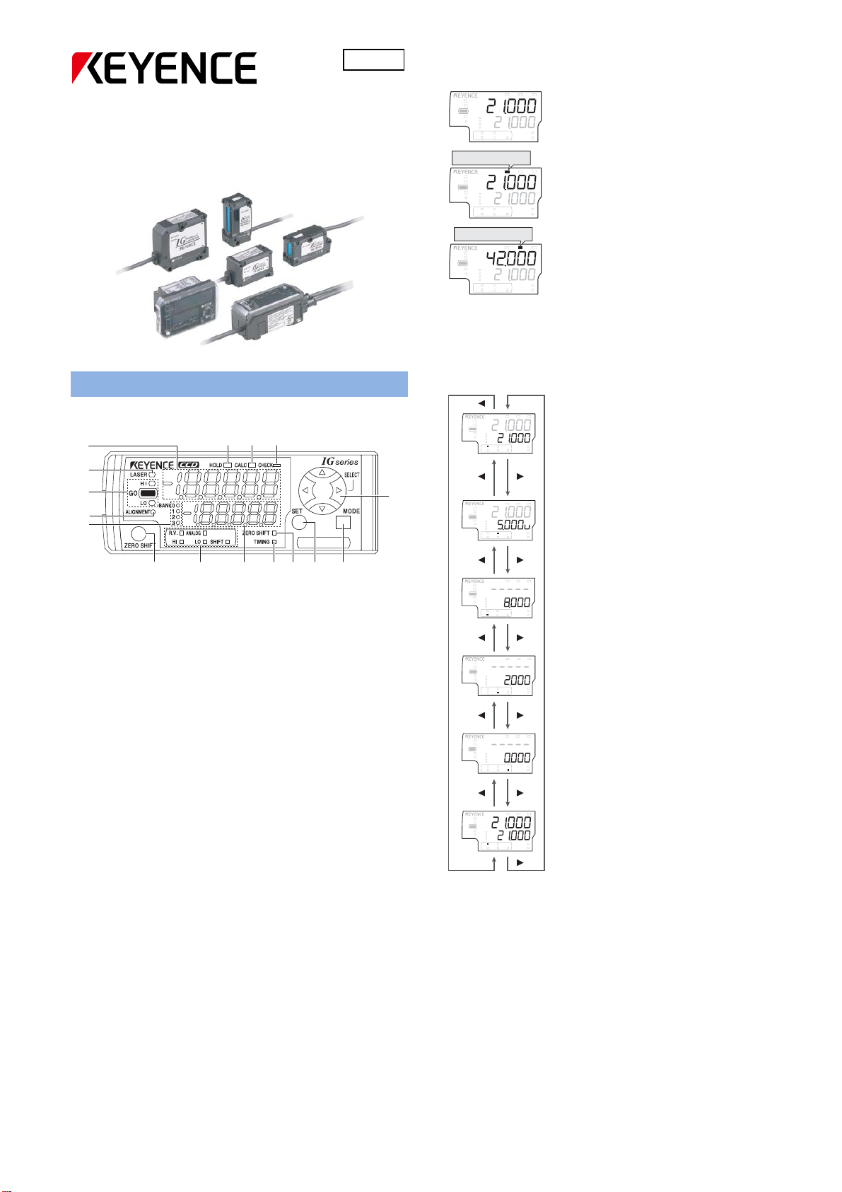
Names of the part of the amplifier
(1)
(2)
(3)
(4)
(5)
(16) (15) (14)
460GB
(13)
Digital LED Display
● Main Display
LASER
GO
ALIGNMENT
LASER
GO
ALIGNMENT
LASER
GO
ALIGNMENT
HOLD CALC
HI
LO
BANK
0
1
2
3
ANALOG
R.V.
HI SHIFT
LO
[HOLD] lights up.
HOLD CALC
HI
LO
BANK
0
1
2
3
ANALOG
R.V.
HI SHIFT
LO
[CALC] lights up.
HOLD CALC
HI
LO
BANK
0
1
2
3
ANALOG
R.V.
HI SHIFT
LO
ZERO SHIFT
ZERO SHIFT
ZERO SHIFT
CHECK
Normal
The internal measurement value is
displayed.
TIMING
CHECK
When Hold function is used
The held value is displayed.
TIMING
CHECK
When Calculation function is used
Main:The calculation result is displayed.
When the hold mode is used, the value
TIMING
would be held also.
Expansion:The measurement value of the
expansion unit itself is displayed.
● Sub display
The Sub display can be switched by pressing the left/right arrow
buttons.
LASER
GO
ALIGNMENT
LASER
GO
ALIGNMENT
HOLD CALC
HI
LO
BANK
0
1
2
3
ZERO SHIFT
ANALOG
R.V.
HI SHIFT
LO
HOLD CALC
HI
LO
BANK
0
1
2
3
ZERO SHIFT
ANALOG
R.V.
HI SHIFT
LO
CHECK
R.V.(Internal measurement value)
The actual measurement value is
displayed. This is not held.
TIMING
CHECK
Analog output (when it is set ON)
The voltage value (V) or the current
(mA) value is displayed.
TIMING
(6) (7) (8) (9) (10) (11) (12)
(1) Main display
(2) Laser emission LED
(3) Judgment LED
(4) Analog range LED
(5) Program bank LED
(6) ZERO SHIFT button
(7) Sub display explanation LED
(8) Sub display
(9) Timing input LED
(10) Zero Shift input LED
(11) SET button
(12) MODE button
(13) Arrow buttons
(14) Alarm LED
(15) Calculation LED
(16) Hold input LED
HOLD CALC
CHECK
LASER
GO
ALIGNMENT
LASER
GO
ALIGNMENT
LASER
GO
ALIGNMENT
HI
LO
BANK
0
1
2
3
ZERO SHIFT
ANALOG
R.V.
LO
HI SHIFT
HOLD CALC
HI
LO
BANK
0
1
2
3
ZERO SHIFT
ANALOG
R.V.
HI SHIFT
LO
HOLD CALC
HI
LO
BANK
0
1
2
3
ZERO SHIFT
R.V.
ANALOG
LO
HI
SHIFT
HIGH Limit setting value
The upper limit set is displayed.
TIMING
CHECK
LOW limit setting value
The lower limit set is displayed.
TIMING
CHECK
Shift target value
When the ZERO SHIFT button is
pressed, the R.V. will be matched to
TIMING
the value set here.
HOLD CALC
CHECK
LASER
GO
ALIGNMENT
HI
LO
BANK
0
1
2
3
ZERO SHIFT
ANALOG
R.V.
HI SHIFT
LO
Calculation value
The Calculation value is displayed. This
is not held.
TIMING
1
Page 2
r
Setup Functions
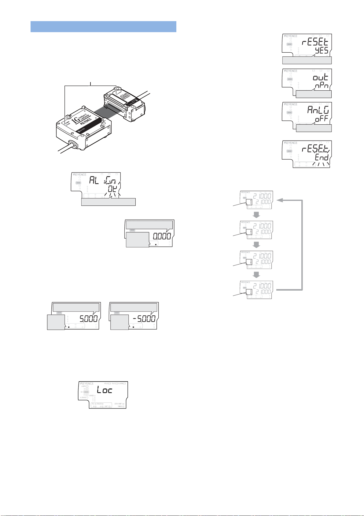
Registering the standard waveform
To measure the target stable, the standard waveform must be
registered first.
1. Confirm that the laser transmitted from the transmitter is reaching
the receiver properly, and the [ALIGNMENT] lamp is lighting.
Optical axis alignment indicator [ALIGNMENT]
Receive
Transmitter
2. Press [MODE] and [SET] for at least 2 seconds.
The standard waveform will be registered.
HOLD CALC
LASER
HI
GO
LO
BANK
0
1
ALIGNMENT
2
3
ANALOG
R.V.
HI SHIFT
LO
Registration complete
Set the R.V. value to the Shift target value
1. Press the left/right arrow buttons until
the sub display shows the Shift target
value.
2. Press the up/down arrow button to change the Shift target value.
3. Press the [ZERO SHIFT] button.
4. The current R.V. value would be set to the Shift target value.
Set the HIGH and LO tolerance.
1. Press the left/right arrow buttons until the sub display shows the
HIGH/LOW limit setting value.
HOLD CALC
LASER
HIGH tolerance value
HI
GO
LO
BANK
0
1
ALIGNMENT
2
[HI]
3
ANALOG
R.V.
lights up.
HI SHIFT
LO
CHECK
ZERO SHIFT
TIMING
2. Input the HIGH or LO tolerance by pressing the up/down arrow
buttons.
3. The HIGH and LOW tolerance will be set.
Setting the Key Lock
1. Press the [MODE] and the up (or down) arrow button for at least 2
seconds.
CHECK
ZERO SHIFT
TIMING
LASER
HI
GO
LO
ALIGNMENT
[SHIFT]
lights up.
LASER
LOW tolerance value
HI
GO
LO
BANK
0
1
ALIGNMENT
2
[LO]
3
ANALOG
R.V.
lights up.
HI SHIFT
LO
HOLD CALC
Shift target value
BANK
0
1
2
3
ANALOG
R.V.
HI SH IFT
LO
HOLD CALC
CHECK
ZERO SHIFT
TIMING
CHECK
ZERO SHIFT
TIMING
Initializing the sensor
HOLD CALC
HOLD CALC
HOLD CALC
CHECK
ZERO SHIFT
TIMING
CHECK
ZERO SHIFT
TIMING
CHECK
ZERO SHIFT
TIMING
1. Press the SET button 5 times while
pressing the MODE button. The main
display will show “rESET”.
2. Select “YES” by pressing the up/down
arrow button, and press the [MODE]
button. The main display will show “out”.
3. Select the output polarity from “NPN”
and “PNP” by pressing the up/down
arrow button, and press the [MODE]
button. The main display will show
“AnLG”.
LASER
HI
GO
LO
BANK
0
1
ALIGNMENT
2
3
ANALOG
R.V.
HI SHIFT
LO
Performing the initial reset
LASER
HI
GO
LO
BANK
0
1
ALIGNMENT
2
3
ANALOG
R.V.
HI SHIFT
LO
Output polarity
LASER
HI
GO
LO
BANK
0
1
ALIGNMENT
2
3
ANALOG
R.V.
HI SHIFT
LO
Analog output
HOLD CALC
4. Select the analog output from “oFF”,
“0-5V”, “-5-5V”, “1-5V” and “4-20mA” by
pressing the up/down arrow button, and
press the [MODE] button. The sensor
will be initialized.
LASER
HI
GO
LO
ALIGNMENT
BANK
0
1
2
3
R.V.
HI SHIFT
ANALOG
LO
CHECK
ZERO SHIFT
TIMING
Changing the bank (program)
1. Press the up/down arrow button while pressing the [MODE] button.
HOLD CALC
<While Bank 0 is selected>
BANK 0 lights
< While Bank 1 is selected>
BANK 1 lights
< While Bank 2 is selected>
BANK 2 lights
< While Bank 3 is selected>
BANK 3 lights
LASER
GO
ALIGNMENT
LASER
GO
ALIGNMENT
LASER
GO
ALIGNMENT
LASER
GO
ALIGNMENT
HI
LO
BANK
HI
LO
BANK
HI
LO
BANK
HI
LO
BANK
0
1
2
3
ZERO SHIFT
ANALOG
R.V.
HI SHIFT
LO
Press ▼ while holding
down the [MODE] button.
HOLD CALC
0
1
2
3
ZERO SHIFT
ANALOG
R.V.
HI SHIFT
LO
Press ▼ while holding
down the [MODE] button.
HOLD CALC
0
1
2
3
ZERO SHIFT
ANALOG
R.V.
HI SHIFT
LO
Press ▼ while holding
down the [MODE] button.
HOLD CALC
0
1
2
3
ZERO SHIFT
R.V.
ANALOG
HI SHIFT
LO
CHECK
TIMING
CHECK
TIMING
CHECK
TIMING
CHECK
TIMING
Press ▼ while
holding down the
[MODE] button.
2. The bank (program) would be switched to another one. Each bank
(program) will have an own HIGH limit setting value/LOW limit
setting value/Shift target value/Sensitivity setting/Binarization
level/Number of filter/Number of pin/Edge number 1 and 2.
2. The Key Lock display would appear.
Canceling the Key Lock
1. When the Key Lock is set, press the MODE and the up (or down)
arrow button for at least 2 seconds.
2. The Key Lock would be cancelled.
2
Page 3

Basic setting mode
How to enter the Basic setting mode
1. Press the [MODE] button for at least 2 seconds.
04 Output method
LASER
HI
GO
LO
ALIGNMENT
2. Press the [MODE] or left/right arrow button and select the function
number.
Set the output status from [Normally Open] or [Normally Closed].
01 Measurement mode
HOLD CALC
LASER
HI
GO
LO
ALIGNMENT
BANK
0
1
2
3
R.V.
HI SHIFT
ANALOG
LO
CHECK
ZERO SHIFT
TIMING
Set the measurement mode from [Edge control], [Outer diameter],
[Inner diameter], [Glass edge], [Pin position], [Pin interval], [Pin
diameter] and [Specified edge].
[Edge control]:
When the measurement direction is set to the “top” side
Top
Bottom
Top
Bottom
R.V.
Measurement
range
When the measurement direction is set to the “bottom” side
Top
Top
BANK
0
1
2
3
R.V.
HI SHIFT
ANALOG
LO
HOLD CALC
CHECK
ZERO SHIFT
TIMING
R.V.
Bottom
Bottom
[Outer diameter]:
Top
Bottom
Top
Bottom
R.V.
Bottom
Top
Top
R.V.
Bottom
[Inner diameter]:
Top
Bottom
Top
Bottom
R.V.
Bottom
Top
Top
R.V.
Bottom
[Glass edge]:
The operation is the same as [Edge control], but the measurement
sensitivity is higher.
02 Measurement direction
HOLD CALC
LASER
HI
GO
LO
ALIGNMENT
BANK
0
1
2
3
R.V.
HI SHIFT
ANALOG
LO
CHECK
ZERO SHIFT
TIMING
Set the measurement direction from [Top] or [Bottom].
[Top]: Measures the distance from the top side of the sensor head to
the edge.
[Bottom]: Measures the distance from the bottom side of the sensor
head to the edge.
03 Averaging(Response time)
HOLD CALC
LASER
HI
GO
LO
ALIGNMENT
BANK
0
1
2
3
R.V.
HI SHIFT
ANALOG
LO
CHECK
ZERO SHIFT
TIMING
Set the average number of times. If the average number of times is set
higher, the response time becomes longer, but the detection will be
more stable.
3
Page 4

Advanced setting mode
How to enter the Advanced setting mode
1. Press the [MODE] button for at least 2 seconds.
HOLD CALC
HOLD CALC
CHECK
ZERO SHIFT
TIMING
CHECK
ZERO SHIFT
TIMING
2. Press the [MODE] or left/right arrow
button until the sub display will show
“End”.
3. Press the up/down arrow button. The
main display will show “Pro”.
LASER
GO
LASER
GO
HI
LO
HI
LO
BANK
0
1
2
3
R.V.
HI SHIFT
BANK
0
1
2
3
R.V.
HI SHIFT
ANALOG
LO
ANALOG
LO
4. Press the [MODE] or left/right arrow button and select the function
number.
Function Explanation
05 Hold function
Set how to hold the value from
[Sample], [Peak], [Bottom],
[Peak to peak], [Auto peak] and
[Bottom peak].
06 Timing input
Set how the timing input for the
hold function is used from
07 Delay timer
[Level] and [Edge].
Set the delay timer for the
judgment output from [Off],
[ON-delay], [OFF-delay] and
[1-shot].
08 Hysteresis
Set the hysteresis for the
judgment value.
09 Edge check function
Set the Edge check function,
which will tell you if the number
of edges inside the
measurement range is correct.
10 Analog output scaling
Set how the analog voltage or
current should output, related to
11 External input
the value.
Assign each input function to
the 4 external inputs.
12 Memorizing the standard
waveform
Set if the standard waveform
has to be memorized to the
EEPROM or not, when the
registration was done by the
external input.
13 Memorizing the zero shift
Set if the shift target value has
to be memorized to the
EEPROM or not, when the zero
shift was input.
14 Interference prevention
Set to use the interference
prevention function.
15 Display digit
Set the number of digits from
[Default], [0.001], [0.01], [0.1]
16 Power saving
and [1].
Set to use the power saving
function.
17 Position monitor
Set the lighting conditions for
the light on the sensor head.
18 Display color
Set the color of the judgment
light, and the color of the main
display.
4
1114-1
 Loading...