


 Loading...
Trio
AG-203
CR Oscillator
Instruction Manual
Contents
Features |
3 |
Specifications |
4 |
Circuit Description |
6 |
Panel Controls and Their Functions |
8 |
Operating Instructions |
10 |
Applications |
12 |
Maintenance |
15 |
Adjustment |
16 |
Caution |
17 |
Parts List |
18 |
PC Board |
21 |
Schematic Diagram |
22 |
Features
•All solid-state circuitry ensure extreme high stability, minimum warm-up time and less power consumption.
•High reliability with adoption of direct coupled circuits throughout the entire stage.
•Compact styling with vertical type panel for easy operation.
•Frequency dial scale calibrated with single-scale graduations for frequency range 10Hz to 1MHz selectable in 5 ranges.
•High output design; more than 7V rms at no load and more than 3.5V rms at 600Ω. Output level is fully adjustable with a 10dB step, 6 range attenuator and a level indicator.
•Low output impedance of 600Ω. The attenuator provides accuracy of ±1dB at 600Ω load.
•Sine and Square waves easily available.
•Synchronizing input terminal.
•Extremely high stability against variation of power source.
Specifications
Frequency Range
Frequency accuracy
(Sine Wave Characteristics)
Output voltages (no-load)
Frequency Characteristics
(reference freq. 1KHz)
Distortion Factor
(Square wave characteristic)
x 1 range; 10Hz – 100Hz x 10 range; 100Hz – 1KHz
x100 range; 1KHz – 10KHz x 1K range; 10KHz – 100KHz
x 10K range; 100KHz – 1MHz
±(3% ±1Hz)
7V rms or more
10Hz – 1MHz, ±1dB
400Hz – 20KHz, 0.1% or less 100Hz – 100KHz, 0.3% or less (x 10 range for 100Hz) 50Hz – 200KHz, 0.5% or less 20Hz – 500KHz, 1% or less 10Hz – 1MHz, 1.5% or less
Output Voltage (no load) |
10V p-p or more |
Sag: |
5% or less at 50Hz |
Rise and Fall times: |
200ns or less |
Overshoot: |
2% or less (at 1KHz, max output) |
Duty ratio: |
50% ±5% (at 1KHz, max output) |
(External Synchronization Characteristics) |
|
Synchronization range: |
±1V |
Max, allowable input voltage: |
10V rms |
Input impedance: |
Approx 10KΩ |
Output impedance: |
600Ω ±10% |
Output attenuator: |
0dB, -10dB, -20dB, -30dB, -40dB, |
|
and –50dB in 6 steps (accuracy: |
|
±1dB at 600Ω load. |
(Stability against power source voltage variation (with respect to variation of 100V ±10%))
Frequency drift: |
Within ±5% |
Output Voltage Variation: |
Within ±0.5dB |
Operating Temperature: |
0-50°(relative humidity less than |
Power Requirements: |
90%) |
AC 100V (120V, 220V or 240V), 50- |
|
Power Consumption: |
60Hz |
5 Watts |
|
External View: |
See Fig. 2 on page 9 |
Dimensions: |
Casing 128(W) x 238(D) x |
|
190(H)mm. |
|
Overall (including knobs); 130(w) x |

Weight: |
268(D) x 215(H)mm. |
2.9kg. |
|
Accessories: |
Power cord (1) |
|
Output cord; one red and black test |
|
cord with basket clip and antenna |
|
plug. |
|
Banana plug; red (1) and black (1) |
|
Fuse; 0.125A (2) and 0.2A (2) |
|
Instruction Manual (1) |
Circuit Description
1. Summary
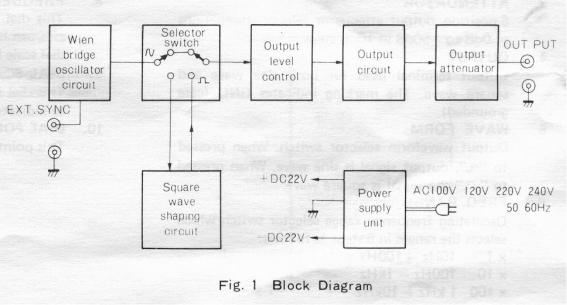
When reading the following descriptions, refer to the block diagram (Fig. 1) and the schematic diagram.
The sine-wave signal generated by the Wien bridge oscillator circuit is fed through the WAVE FORM selector switch set at the " ~ " position to the OUTPUT control, by means of which it is adjusted to any desired voltage.
If the WAVE FORM switch is in the “ _” position, the sine-wave signal is shaped into the square wave and the voltage is also adjusted by the OUTPUT control.
The signal voltage thus adjusted is applied to the output circuit, where its impedance is appropriately converted, and then delivered through an output attenuator to the output terminal. The attenuator provides selectable attenuations of 0dB through -50dB in 10dB steps at 600Ω of output impedance.
2. Wien Bridge Oscillator Circuit
The Wien bridge oscillator circuit elements consist of the resistance elements, which may be switched over for 5 ranges by the FREQ. RANGE switch, and the variable capacitor controlled by the FREQUENCY dial.
These elements provide means to vary the oscillating frequency continuously over 10 times its frequency on one range, thus determining any desired frequency within the entire frequency range from 10Hz to 1MHz.
The amplifier circuit for the oscillator circuit is composed of a 2-stage differential amplifier and an output stage, employing an DC amplifier circuit. The first stage is a high input impedance circuit with FET while the driver stage is a wide band, high amplification type circuit with PNP transistors featuring high cut-off frequency. The output stage is a SEPP circuit using complementary transistors.
The output voltage is fed back with positive polarity through the oscillator elements to form an oscillating circuit, while it is also fed back with negative polarity through the non-linear thermistor to stabilize the amplitude.
3. Square Wave Shaping Circuit
The square wave shaping circuit is a Schmidt-trigger circuit in which the sine wave signal from the oscillator circuit is shaped into a square wave. It is composed of an emitter coupled Schmidt-trigger circuit and a buffer amplifier, thus providing sufficient rising and falling characteristics.
4. Output Circuit
The output circuit converts the impedance of signal from the OUTPUT control and feeds the signal to the output attenuator at a low impedance. It is a SEPP-OCL circuit employing complementary transistors to provide sufficiently low output impedance characteristics over the range from DC to 1MHz.
5. Output Attenuator
The 6-position output attenuator selects attenuations of 0dB to -50dB in 10dB steps. At the 0dB position with the OUTPUT control turned fully clockwise, the output voltage (sine wave at no-load time) is more than 7V rms.
The output impedance is rated for 600Ω and the attenuation accuracy is as high as ±1.0dB at a 600Ω load.
6. Power Supply
The Power supply circuit is powered by AC (100V, 120V or 220V) and delivers DC ±22V sufficiently stabilized by large capacity smoothing capacitors (220OmF x 2) and a voltage stabilizer.
Panel Controls and Their Functions
The table below describes the functions of panel controls. Refer to the panel diagram on page 9. (Fig 2)
FRONT PANEL
This lamp (light emitting diode) lights when POWER switch (2) is ON.
2.POWER
Pushbutton type switch turns on the power when pressed.
3.ATTENUATOR
6-position output attenuator selects attenuations of 0dB to -50dB in 10dB steps.

4.OUTPUT
Output terminal used for both sine wave and square wave. The marking indicates GND (case grounded).

5.WAVE FORM
Output waveform selector switch. When pressed to “~”, output signal is sine wave. When pressed to “_” the signal is square wave.
6.FREQ. RANGE
Oscillating frequency range selector switch which selects the ranges in 5 steps as follows:
X 1 10Hz -100Hz x10 100HzlkHz x100 1kHz - 10kHz
x 1K 10KHz – 100KHz x 10K 100KHz – 1MHz
7.Amplitude
Amplitude adjuster to continuously vary the amplitude of output voltage.
8.FREQUENCY DIAL
This dial adjusts oscillating frequencies. Frequencies can be read by multiplying the reading on the dial scale by magnification of FREQ.RANGE.
9.DIAL SCALE
This dial is calibrated with graduations of 10-100 to indicate oscillating frequencies.
10.DIAL POINTER
This pointer indicates frequencies on the dial scale.
REAR PANEL
11.Sync.
External synchronizing signal input terminals fir GND for connection of synchronizing signal to AG-203.
12.Fuse
Fuse fore Power supply.
13.A.C. Connector
For connection of the supplied A.C. connector.
14.Power Voltage Selector.
This selector is preset to 240V position. A.C. power of 100V, 120V or 220V may be used by changing the position of the selector.
Operating Instructions
1. Start-up
First check that the fuse (12) and the power voltage selector (14) are in the normal positions, then connect the supplied AC power cord to your AC outlet. Press the power switch (2) and the pilot lamp (1) will light indicating that the unit is ready for operation. Allow 2 or 3 minutes for the unit to warm up so that it is stabilized.
Loading...