


 Loading...
JVC AV-32230/G, AV-32230/H, AV-32230/M, AV-32260/G, AV-32260/H Service Manual
...AV-32230
AV-32260
SERVICE MANUAL
COLOR TELEVISION
BASIC CHASSIS
AV-32230 AV-32230 AV-32230
/G
/H
/M
AV-32260 AV-32260 AV-32260
AC
/G
/H
/M
TV |
TV |
|
RM-C306 |
RM-C305 |
|
[AV-32230] [AV-32260] |
|
|
CONTENTS |
|
|
a SPECIFICATIONS |
.................................................................................................................................... |
2 |
a SAFETY PRECAUTIONS ........................................................................................................................ |
3 |
|
a FEATURES .............................................................................................................................................. |
|
5 |
a MAIN DIFFERENCE LIST ........................................................................................................................ |
6 |
|
a HOW TO IDENTIFY MODELS .................................................................................................................. |
6 |
|
a FUNCTIONS ............................................................................................................................................. |
|
7 |
a SPECIFIC SERVICE INSTRUCTIONS .................................................................................................... |
8 |
|
a SERVICE ADJUSTMENTS .................................................................................................................... |
13 |
|
¤ STANDARD CIRCUIT DIAGRAM (APPENDIX) .................................................................................. |
2-1 |
|
a PARTS LIST ........................................................................................................................................... |
|
35 |
|
|
No. 51802 |
|
COPYRIGHT © 2001 VICTOR COMPANY OF JAPAN, LTD. |
|
|
|
Feb. 2001 |

AV-32230
AV-32260
SPECIFICATIONS
Items |
|
|
|
|
|
Contents |
|
|
|||||
|
|
|
|
|
|
|
Dimensions (W × H × D) |
30-1/4” × 26-1/4” × 21-1/2” / 76.8cm × 66.7cm × 54.7cm |
|||||
················································································································································································································ |
||||||
Mass |
112.2 lbs / 51.0 kg |
|
|
|
||
················································································································································································································ |
||||||
TV RF System |
CCIR(M) |
|
|
|
|
|
················································································································································································································ |
||||||
Color Sound System |
NTSC, BTSC System (Multi Channel Sound) |
|||||
················································································································································································································ |
||||||
TV Receiving Channels and Frequency |
|
|
|
|
|
|
VL Band |
(02~06) 54MHz~88MHz |
|
|
|
||
VH Band |
(07~13) 174MHz~216MHz |
|
|
|
||
UHF Band |
(14~69) 470MHz~806MHz |
|
|
|
||
················································································································································································································ |
||||||
CATV Receiving Channels and Frequency |
|
|
|
|
|
|
Low Band |
(02~06, A-8) by (02~06&01) |
— |
|
|
||
|
||||||
High Band |
(07~13) by (07~13) |
|
|
|
||
Mid Band |
(A~1) by (14~22) |
|
|
|
||
Super Band |
(J~W) by (23~36) |
|
|
(54MHz~804MHz) |
||
Hyper Band |
(W+1~W+28) by (37~64) |
|
|
|
||
Ultra Band |
(W+29~W+84) by (65~125) |
|
|
|
||
Sub Mid Band |
(A8, A4~A1) by (01, 96~99) |
— |
|
|
||
|
||||||
TV/CATV Total Channel |
180 Channels |
|
|
|
|
|
················································································································································································································ |
||||||
Intermediate Frequency |
|
|
|
|
|
|
Video IF Carrier |
45.75MHz |
|
|
|
|
|
Sound IF Carrier |
41.25MHz (4.5MHz) |
|
|
|
||
Color Sub Carrier |
3.58MHz |
|
|
|
|
|
················································································································································································································ |
||||||
Power Input |
120V AC, 60Hz |
|
|
|
||
Power Consumption |
133W [AV-32260], 128W [AV-32230] |
|||||
················································································································································································································ |
||||||
Picture Tube |
32” (80cm) Measured Diagonally |
|
|
|
||
High Voltage |
31kV±1.3kV (at zero beam current) |
|||||
················································································································································································································ |
||||||
Speaker |
2” × 4-3/4” / 5 |
× 12cm Oval type × |
2 |
|
|
|
Audio Power Output |
3W × 2 |
|
|
|
|
|
················································································································································································································ |
||||||
Video / Audio Input (1 / 2 / 3) |
Video(1,2,3) |
: 1Vp-p, 75Ø (RCA pin jack) |
||||
|
Audio(1,2,3) |
: 500mVrms ( -4dBs ), High Impedance (RCA pin jack) |
||||
|
S-Video ( Input 1 Over ) |
|
|
|
||
|
Y |
: 1Vp-p Positive (negative sync provided, when terminated with 75Ø) |
||||
|
C |
: 0.286Vp-p (burst signal, when terminated with 75Ø) |
||||
|
Component Input ( Input 2 ) |
|
|
|
||
|
Y |
: 1Vp-p positive (negative sync provided, when terminated with 75Ø) |
||||
|
PB/PR |
: 0.7Vp-p 75 Ø |
|
|
|
|
················································································································································································································ |
||||||
Audio Output |
Variable |
: More then 0~1550mVrms (+6dBs) |
||||
(Variable) |
|
Low impedance (400Hz when modulated 100%) (RCA pin jack) |
||||
················································································································································································································ |
||||||
AV Compu link EX Input |
3.5mm mini jack |
|
|
|
||
················································································································································································································ |
||||||
Antenna terminal |
75Ø(VHF/UHF) Terminal, F-Type Connector |
|||||
················································································································································································································ |
||||||
Remote Control Unit |
RM-C305-1A [AV-32260], RM-C306-1A [AV-32230] |
|||||
|
(AA/R6/UM-3 battery × 2) |
|
|
|
||
|
|
|
|
|
|
|
Design & specifications are subject to change without notice.
2 |
No. 51802 |
AV-32230
AV-32260
SAFETY PRECAUTIONS
1.The design of this product contains special hardware, many circuits and components specially for safety purposes. For continued protection, no changes should be made to the original design unless authorized in writing by the manufacturer. Replacement parts must be identical to those used in the original circuits. Service should be performed by qualified personnel only.
2.Alterations of the design or circuitry of the products should not be made. Any design alterations or additions will void the manufacturer's warranty and will further relieve the manufacturer of responsibility for personal injury or property damage resulting therefrom.
3.Many electrical and mechanical parts in the products have special safety-related characteristics. These characteristics are often not evident from visual inspection nor can the protection afforded by them necessarily be obtained by using replacement components rated for higher voltage, wattage, etc. Replacement parts which have these special safety characteristics are identified in the parts list of Service manual. Electrical components having such features are identified by shading on the schematics and by (  ) on the parts list in Service manual. The use of a substitute replacement which does not have the same safety characteristics as the recommended replacement part shown in the parts list of Service manual may cause shock, fire, or other hazards.
4.Use isolation transformer when hot chassis.
The chassis and any sub-chassis contained in some products are connected to one side of the AC power line. An isolation transformer of adequate capacity should be inserted between the product and the AC power supply point while performing any service on some products when the HOT chassis is exposed.
5.Don't short between the LIVE side ground and ISOLATED (NEUTRAL) side ground or EARTH side ground when repairing.
Some model's power circuit is partly different in the GND. The dif-
ference of the GND is shown by the LIVE : (  ) side GND, the ISOLATED(NEUTRAL) : (
  ) side GND and EARTH : (
  ) side GND. Don't short between the LIVE side GND and
ISOLATED(NEUTRAL) side GND or EARTH side GND and never measure with a measuring apparatus (oscilloscope etc.) the LIVE side GND and ISOLATED(NEUTRAL) side GND or EARTH side
GND at the same time.
If above note will not be kept, a fuse or any parts will be broken.
6.If any repair has been made to the chassis, it is recommended that the B1 setting should be checked or adjusted (See ADJUSTMENT OF B1 POWER SUPPLY).
7.The high voltage applied to the picture tube must conform with that specified in Service manual. Excessive high voltage can cause an increase in X-Ray emission, arcing and possible component damage, therefore operation under excessive high voltage conditions should be kept to a minimum, or should be prevented. If severe arcing occurs, remove the AC power immediately and determine the cause by visual inspection (incorrect installation, cracked or melted high voltage harness, poor soldering, etc.). To maintain the proper minimum level of soft X-Ray emission, components in the high voltage circuitry including the picture tube must be the exact replacements or alternatives approved by the manufacturer of the complete product.
8.Do not check high voltage by drawing an arc. Use a high voltage meter or a high voltage probe with a VTVM. Discharge the picture tube before attempting meter connection, by connecting a clip lead to the ground frame and connecting the other end of the lead through a 10kØ 2W resistor to the anode button.
9.When service is required, observe the original lead dress. Extra precaution should be given to assure correct lead dress in the high voltage circuit area. Where a short circuit has occurred, those components that indicate evidence of overheating should be replaced.
Always use the manufacturer's replacement components.
10.Isolation Check
(Safety for Electrical Shock Hazard)
After re-assembling the product, always perform an isolation check on the exposed metal parts of the cabinet (antenna terminals, video/
audio input and output terminals, Control knobs, metal cabinet, screwheads, earphone jack, control shafts, etc.) to be sure the product is safe to operate without danger of electrical shock.
(1)Dielectric Strength Test
The isolation between the AC primary circuit and all metal parts exposed to the user, particularly any exposed metal part having a return path to the chassis should withstand a voltage of 1100V AC (r.m.s.) for a period of one second.
(. . . . Withstand a voltage of 1100V AC (r.m.s.) to an appliance rated up to 120V, and 3000V AC (r.m.s.) to an appliance rated 200V or more, for a period of one second.)
This method of test requires a test equipment not generally found in the service trade.
(2)Leakage Current Check
Plug the AC line cord directly into the AC outlet (do not use a line isolation transformer during this check.). Using a “Leakage Current Tester”, measure the leakage current from each exposed metal part of the cabinet, particularly any exposed metal part having a return path to the chassis, to a known good earth ground (water pipe, etc.). Any leakage current must not exceed 0.5mA AC (r.m.s.).
However, in tropical area, this must not exceed 0.2mA AC (r.m.s.).
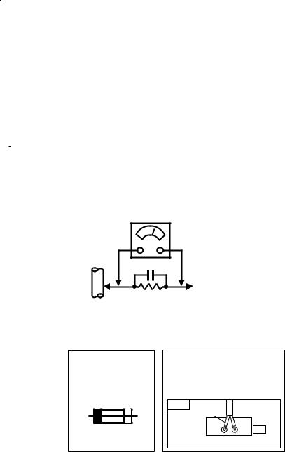
• Alternate Check Method
Plug the AC line cord directly into the AC outlet (do not use a line isolation transformer during this check.). Use an AC voltmeter having 1000 ohms per volt or more sensitivity in the following manner.
Connect a 1500Ø 10W resistor paralleled by a 0.15µF AC-type capacitor between an exposed metal part and a known good earth ground (water pipe, etc.). Measure the AC voltage across the resistor with the AC voltmeter. Move the resistor connection to each exposed metal part, particularly any exposed metal part having a return path to the chassis, and measure the AC voltage across the resistor. Now, reverse the plug in the AC outlet and repeat each measurement. Any voltage measured must not exceed 0.75V AC
(r.m.s.). This corresponds to 0.5mA AC (r.m.s.).
However, in tropical area, this must not exceed 0.3V AC (r.m.s.). This corresponds to 0.2mA AC (r.m.s.).
|
AC VOLTMETER |
|
(HAVING 1000Ø/V, |
GOOD |
OR MORE SENSITIVITY) |
|
|
EARTH |
|
GROUND 0.15 F AC-TYPE |
|
|
PLACE THIS PROBE |
|
ON EACH EXPOSED |
1500Ø 10W |
METAL PART |
|
11.High voltage hold down circuit check.
After repair of the high voltage hold down circuit, this circuit shall be checked to operate correctly.
See item “How to check the high voltage hold down circuit”.
This mark shows a fast operating fuse, the letters indicated below show the rating.
 A
A 
 V
V
POWER CORD REPLACEMENT WARNING Connecting thr white line side of
power cord to “WHT” character side.
PWB
White line side
PW
WHT
No. 51802 |
3 |
AV-32230
AV-32260
REPLACEMENT OF CHIP COMPONENT
aCAUTIONS
1.Avoid heating for more than 3 seconds.
2.Do not rub the electrodes and the resist parts of the pattern.
3.When removing a chip part, melt the solder adequately.
4.Do not reuse a chip part after removing it.
aSOLDERING IRON
1.Use a high insulation soldering iron with a thin pointed end of it.
2.A 30w soldering iron is recommended for easily removing parts.
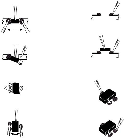
aREPLACEMENT STEPS
1.How to remove Chip parts
 Resistors, capacitors, etc.
(1)As shown in the figure, push the part with tweezers and alternately melt the solder at each end.
(2) Shift with tweezers and remove the chip part.
2.How to install Chip parts
 Resistors, capacitors, etc.
(1)Apply solder to the pattern as indicated in the figure.
(2)Grasp the chip part with tweezers and place it on the solder.
Then heat and melt the solder at both ends of the chip part.
 Transistors, diodes, variable resistors, etc.
(1) Apply extra solder to each lead.
SOLDER |
SOLDER |
(2)As shown in the figure, push the part with tweezers and alternately melt the solder at each lead. Shift and remove the chip part.
Note : After removing the part, remove remaining solder from the pattern.
 Transistors, diodes, variable resistors, etc.
(1)Apply solder to the pattern as indicated in the figure.
(2)Grasp the chip part with tweezers and place it on the solder.
(3)First solder lead A as indicated in the figure.
A
 B
B
C
(4) Then solder leads B and C.
A
 B
B
C 
4 |
No. 51802 |
FEATURES
•Full-square CRT (cathode ray tube) reproduces fine textured picture in every detail.
•I2C bus control utilizes single chip ICs.
•Built in Twin Tuner system. [Only for AV-32260 model]
•Built-in HYPER-SURROUND system.
•Adoption of the Picture-In-Picture (PIP) function. [Only for AV-32260 model]
AV-32230
AV-32260
•3 LINE DIGITAL COMB FILTER circuit improved picture quality.
•Component input terminal for talking best advantage of Component
Video Signal.
•Audio Video input terminal. (S-input ×1, V-input ×2)
•Variable audio output terminal.
•Closed-caption broadcasts can be viewed.
•With AV COMPU LINK EX terminal.
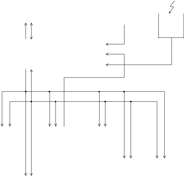
a SYSTEM BLOCK DIAGRAM
IC702 |
(Only for AV-32260 model) |
|
||
E2PROM 4k bit |
|
|||
|
|
|
|
|
|
IF2 |
|
Remote |
|
|
|
|
||
|
|
|
|
|
|
|
|
|
control |
|
|
|
|
|
|
|
|
|
unit |
SCL 1 |
SDA 1 |
|
AFC 2 |
IC701 |
AFC 1 |
|
|
MAIN MICON |
|
|
|
SCL 0 |
SDA 0 |
IC301 |
|
|
|
IC101 |
|
IC501 |
|
|
|
|
||
PIP |
|
|
|
1 CHIP |
|
AVSW |
|
|
|
|
||
CONTROL |
|
|
CONTROL |
|
CONTROL |
|
|
|
|
|||
|
|
|
|
|
|
|
|
|
|
|
|
|
(Only for AV-32260 |
|
|
|
|
|
|
|
|
|
|||
model) |
|
|
|
|
|
|
|
|
|
|||
|
|
|
|
|
TU001 |
|
TU001 |
|
||||
|
|
|
|
|
|
|
|
|
|
|
||
|
|
|
|
|
|
|
|
TUNER 1 |
|
TUNER 2 |
|
|
|
|
|
|
|
|
|
|
|
|
|
|
|
|
IC001 |
|
|
|
|
|
|
(Only for AV-32260 |
||||
|
|
|
|
|
|
|
model) |
|||||
|
MTS, TONE |
|
|
|
|
|
|
|||||
|
|
|
|
|
|
|
|
|
|
|||
|
SURROUND CONTROL |
|
|
|
|
|
|
|
||||
|
|
|
|
|
|
|
|
|
|
|
|
|
No. 51802 |
5 |
AV-32230
AV-32260
MAIN DIFFERENCE LIST
[AV-32230/G & AV-32230/H & AV-32230/M]
! |
|
Model |
AV-32230/G |
AV-32230/H |
AV-32230/M |
||
Part name |
|
||||||
|
|
|
|
|
|
||
|
MAIN PWB |
|
SAC-1535A-M2 |
SAC-1536A-M2 |
SAC-1537A-M2 |
||
|
|
|
|
|
|
|
|
|
CRT SOCKET PWB |
|
SAC-3508A-M2 |
SAC-3509A-M2 |
SAC-3510A-M2 |
||
|
|
|
|
|
|
|
|
! |
PICTRE TUBE |
|
A80QCF240X14L |
A80LJF30X08-G |
M80JUA061X06 |
||
|
|
|
|
|
|
|
|
! |
DEG. COIL |
|
QQW0086-001 |
CELD066-002JA |
|
|
|
|
|
|
|||||
|
|
|
|
|
|
|
|
[AV-32260/G & AV-32260/H & AV-32260/M]
! |
|
Model |
AV-32260/G |
AV-32260/H |
AV-32260/M |
||
Part name |
|
||||||
|
|
|
|
|
|
||
|
MAIN PWB |
|
SAC-1529A-M2 |
SAC-1530A-M2 |
SAC-1531A-M2 |
||
|
|
|
|
|
|
|
|
|
CRT SOCKET PWB |
|
SAC-3508A-M2 |
SAC-3509A-M2 |
SAC-3510A-M2 |
||
|
|
|
|
|
|
|
|
! |
PICTURE TUBE |
|
A80QCF240X14L |
A80LJF30X08-G |
M80JUA061X06 |
||
|
|
|
|
|
|
|
|
! |
DEG. COIL |
|
QQW0086-001 |
CELD066-002JA |
|
|
|
|
|
|
|||||
|
|
|
|
|
|
|
|
HOW TO IDENTIFY MODELS
•The difference between AV-32230/G , AV-32230/H and AV-32230/M is in the PICTURE TUBE.
As the result of the difference in PICTURE TUBE, the MAIN PWB also differ.
|
|
Model |
|
|
|
|
|
|
|
|
|
|
|
|||
! |
Part name |
|
AV-32230/G |
|
AV-32230/H |
|
AV-32230/M |
|||||||||
|
|
|
|
|
|
|
|
|
|
|
|
|
|
|
|
|
! |
RATING LABEL |
|
LC31139-001A-A |
|
|
|
|
|
|
|
|
|
|
|
||
|
|
|
|
|
|
|
|
|
|
|
||||||
- - - - - - - - - - - - - - - - - - - - - - - - - - - - - - - - - - - - - - - - - - - - - - - - - - - - - - - - - - - - - - - - - - - - - - - - - - - - - - - - - - - - - - - - - - - - - - - - - - - - - - - - - - - - - - - - - - - - - - - - - - - - - - - - - - - - - |
||||||||||||||||
|
|
|
INDICATED AV-32230 |
|
INDICATED AV-32230 |
|
INDICATED AV-32230 |
|||||||||
|
|
|
|
|
|
|
|
|
|
|
|
|
|
|
|
|
|
|
|
|
|
|
|
|
|
|
|
|
|
|
|
|
|
|
|
|
|
|
|
|
|
|
|
|
|
|
|
|
|
|
|
|
|
|
|
|
|
|
|
|
|
|
|
|
|
|
|
|
|
|
|
|
|
|
|
|
|
|
|
|
|
|
|
|
|
|
|
|
|
|
|
|
|
|
|
|
|
|
|
|
|
INDICATED “G” |
INDICATED “H” |
INDICATED “M” |
6 |
No. 51802 |
AV-32230
AV-32260
•The difference between AV-32260/G , AV-32260/H and AV-32260/M is in the PICTURE TUBE.
As the result of the difference in PICTURE TUBE, the MAIN PWB also differ.
|
|
Model |
|
|
|
|
|
|
|
|
|
|
|
|||
! |
Part name |
|
AV-32260/G |
|
AV-32260/H |
|
AV-32260/M |
|||||||||
|
|
|
|
|
|
|
|
|
|
|
|
|
|
|
|
|
! |
RATING LABEL |
|
LC31139-001A-A |
|
|
|
|
|
|
|
|
|
|
|
||
|
|
|
|
|
|
|
|
|
|
|
||||||
- - - - - - - - - - - - - - - - - - - - - - - - - - - - - - - - - - - - - - - - - - - - - - - - - - - - - - - - - - - - - - - - - - - - - - - - - - - - - - - - - - - - - - - - - - - - - - - - - - - - - - - - - - - - - - - - - - - - - - - - - - - - - - - - - - - - - |
||||||||||||||||
|
|
|
INDICATED AV-32260 |
|
INDICATED AV-32260 |
|
INDICATED AV-32260 |
|||||||||
|
|
|
|
|
|
|
|
|
|
|
|
|
|
|
|
|
|
|
|
|
|
|
|
|
|
|
|
|
|
|
|
|
|
|
|
|
|
|
|
|
|
|
|
|
|
|
|
|
|
|
|
|
|
|
|
|
|
|
|
|
|
|
|
|
|
|
|
|
|
|
|
|
|
|
|
|
|
|
|
|
|
|
|
|
|
|
|
|
|
|
|
|
|
|
|
|
|
|
|
|
|
INDICATED “G” |
INDICATED “H” |
INDICATED “M” |
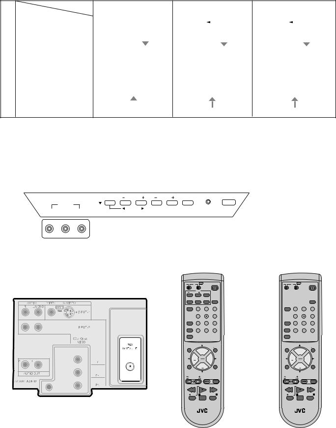
FUNCTIONS
a FRONT PANEL
MENU |
CHANNEL |
VOLUME |
POWER ON TIMER |
|
INPUT3 |
OPERATE |
|
VIDEO |
AUDIO |
||
|
L/MONO R
a REMOTE CONTROL UNIT
(RM-C305-1A) [AV-32260] |
(RM-C306-1A) [AV-32230] |
a REAR PANEL
TV CATV VCR |
DVD |
POWER |
TV CATV VCR |
DVD |
POWER |
|
|
|
|
PIP |
ON/MOVE |
|
|
|
|
|
|
CHANNEL |
|
|
|
|
|
|
|
SOURCE FREEZE |
SWAP |
INPUT |
|
|
|
INPUT |
|
VIDEO STATUS |
1 |
2 |
3 |
VIDEO STATUS |
1 |
2 |
3 |
|
4 |
5 |
6 |
|
4 |
5 |
6 |
DISPLAY |
7 |
8 |
9 |
DISPLAY |
7 |
8 |
9 |
SLEEP TIMER |
100+ |
0 RETURN+ |
SLEEP TIMER 100+ |
0 RETURN+ |
|||
HYPER SURROUND |
|
|
|
HYPER SURROUND |
|
|
|
RM-C305 |
|
|
|
RM-C305 |
|
|
|
MUTING |
+ |
V CHIP |
MUTING |
+ |
|
V CHIP |
|
|
|
|
|
|
|||
|
CH |
|
|
CH |
|
|
|
VOL |
|
VOL |
VOL |
|
VOL |
||
|
|
+ |
|
|
|
+ |
|
|
CH |
EXIT |
|
CH |
|
EXIT |
|
|
|
|
|
|
|||
MENU |
|
|
PIP OFF |
MENU |
|
|
PIP OFF |
VCR CHANNEL |
VCR/DVD |
|
VCR CHANNEL |
VCR/DVD |
|
||
PREV NEXT |
|
POWER |
TV/VCR |
PREV NEXT |
POWER |
TV/VCR |
|
REW |
PLAY |
FF |
REW |
PLAY |
|
FF |
|
REC |
STOP PAUSE |
REC |
STOP |
PAUSE |
|||
OPEN/CLOSE |
|
STILL/PAUSE |
OPEN/CLOSE |
|
STILL/PAUSE |
||
TV TV
No. 51802 |
7 |

AV-32230
AV-32260
SPECIFIC SERVICE INSTRUCTIONS
DISASSEMBLY PROCEDURE
REMOVING THE REAR COVER
1.Unplug the power supply cord.
2.Remove the 11 screws marked A as shown in Fig.1.
3.Withdraw the REAR COVER toward you.
[CAUTION]
•When reinstalling the rear cover, carefully push it inward after inserting the MAIN PWB into the rear cover groove.
REMOVING THE SPEAKER
• After removing the rear cover.
1.Remove the 2 screws marked K as shown in Fig.1.
2.Withdraw the speaker backward.
3.Follow the same steps when removing the other hand speaker.
REMOVING THE CHASSIS
• After removing the rear cover.
1.Slightly raise the both sides of the chassis by hand and remove the 3 claws marked B under the chassis from the front cabinet as shown in Fig.1.
2.Withdraw the chassis backward along the rail in the arrow direction marked C as shown in Fig.1.
(If necessary, take off the wire clamp, connector’s etc.)
*When conducting a check with power supplied, be sure to confirm that the CRT earth wire is connected to the CRT SOCKET PWB
and the MAIN PWB.
REMOVING THE TERMINAL BOARD
• After removing the rear cover.
1.Remove the 4 screws marked D as shown in Fig.1.
2.When you pull out the TERMINAL BOARD in the direction of arrow marked E as shown in Fig.1, it can be removed.
CHECKING THE MAIN PW BOARD
1.To check the back side of the MAIN PW Board.
1)Pull out the chassis. (Refer to REMOVING THE CHASSIS).
2)Erect the chassis vertically so that you can easily check the back side of the MAIN PW Board.
[CAUTION]
•When erecting the chassis, be careful so that there will be no contacting with other PW Board.
•Before turning on power, make sure that the CRT earth wire and other connectors are properly connected.
WIRE CLAMPING AND CABLE TYING
1.Be sure clamp the wire.
2.Never remove the cable tie used for tying the wires together.
Should it be inadvertently removed, be sure to tie the wires with a new cable tie.
REMOVING THE FRONT CONTROL AND FRONT AV INPUT PW BOARDS
• After removing the rear cover and chassis.
1.Remove the 2 screws marked F and the 2 screws marked G as shown in Fig.1.
2.Then remove the FRONT CONTROL PWB and FRONT AV INPUT PWB.
(If necessary, take off the wire, connector’s etc.)
REMOVING THE LF PW BOARD
• After removing the rear cover and chassis.
1. Lift the left side of the LF PWB while pressing the 2 PWB stoppers marked H in the arrow direction marked J as shown in Fig.1.
2.Then remove the LF PWB.
(If necessary, take off the wire, connector’s etc.)
8 |
No. 51802 |

AV-32230
AV-32260
FRONT CABINET
PICTURE TUBE
CRT SOCKET PWB
SPEAKER
K (x2)
FRONT AV INPUT PWB
CLAW PIP PWB (Only for AV-32260 model)
|
PWB |
B |
MAIN PWB |
|
|
||
|
STOPPER |
|
|
G (x2) |
H |
|
|
J |
|
|
|
|
|
|
|
|
|
FRONT |
|
|
F |
(x2) |
CONTROL PWB |
|
|
|
|
||
|
|
CLAW |
|
|
|
|
|
|
|
K |
|
|
B |
|
(x2) |
|
|
|
E |
REAR COVER |
|
|
LF PWB |
|
|
|
|
||
|
|
|
C |
|
|
|
|
AV SELECTOR |
|
|
|
|
PWB |
|
D (x4)
CHASSIS BASE
A (x11)
Fig.1
No. 51802 |
9 |
AV-32230
AV-32260
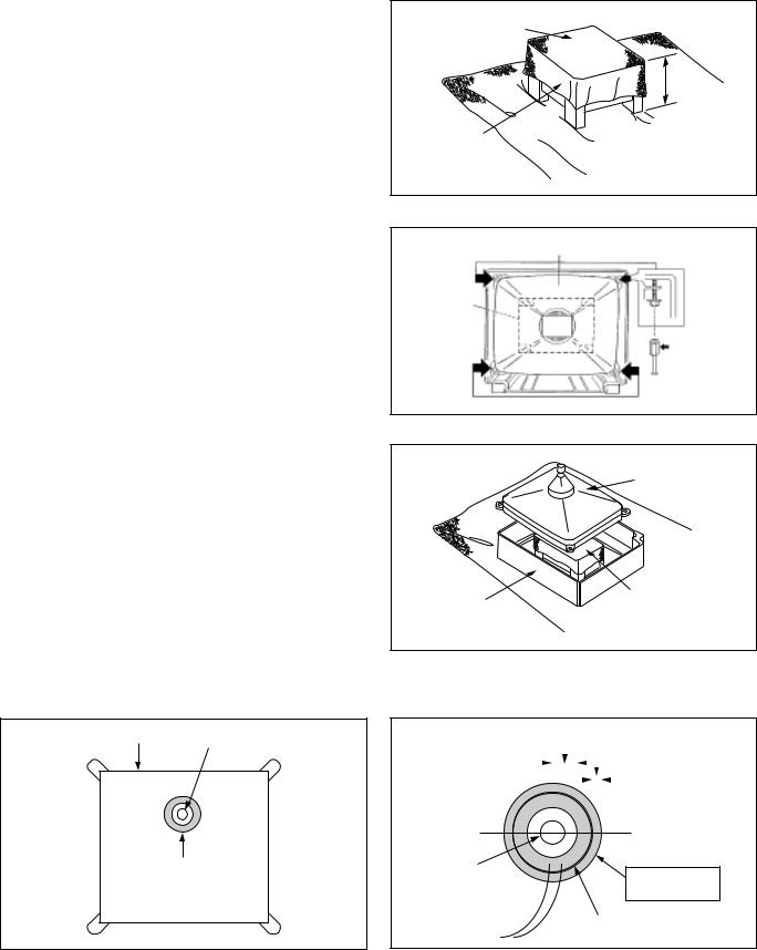
REMOVING THE CRT
* Replacement of the CRT should be performed by 2 or more persons.
• After removing the rear cover, chassis etc.,
1.Putting the CRT change table on soft cloth, the CRT change table should also be covered with such soft cloth (shown in Fig.2).
2.While keeping the surface of CRT down, mount the TV set on the CRT change table balanced will as shown in Fig.3.
3.Remove 4 screws marked by arrows with a box type screwdriver as
shown in Fig.3.
•Since the cabinet will drop when screws have been removed, be sure to support the cabinet with hands.
4.After 4 screws have been removed, put the cabinet slowly on cloth (At this time, be carefully so as not to damage the front surface of the cabinet) shown in Fig.4.
•The CRT should be assembled according to the opposite sequence of its dismounting steps.
*The CRT change table should preferably be smaller that the CRT surface, and its height be about 35cm.
COATING OF SILICON GREASE FOR ELECTRICAL INSULATION ON THE CRT ANODE CAP SECTION.
•Subsequent to replacement of the CRT and HV transformer or repair of the anode cap, etc. by dismounting them, be sure to coat silicon
grease for electrical insulation as shown in Fig.5.
Wipe around the anode button with clean and dry cloth. (Fig.5)
Coat silicon grease on the section around the anode button. At this time, take care so that any silicon greases dose not sticks to the anode button. (Fig.6)
Silicon grease product No. KS - 650N
CRT |
Anode button |
Silicon grease coating
Fig. 5
CRT CHANGE TABLE
APPROX.
35cm
CLOTH 
Fig. 2
CRT
CRT
CHANGE
TABLE
BOX
TYPE
SCREW
DRIVER
Fig. 3
CRT
CABINET |
CRT |
|
CHANGE TABLE |
||
|
Fig. 4
Approx. |
|
|
|
|
|
|
|
|
|
Silicon grease |
||||
20mm (Do not |
|
|
|
|
|
|
|
|
|
|
|
|
|
|
|
|
|
|
|
|
|
|
|
|
|
|
|
should be coated |
|
coat grease on |
|
|
|
|
|
|
|
|
|
|
by 5mm or more |
|||
this section |
|
|
|
|
|
|
|
|
|
|
|
|
||
|
|
|
|
|
|
|
|
|
|
|
|
from the outside |
||
|
|
|
|
|
|
|||||||||
|
|
|
|
|
|
|
|
|
|
|
|
|
|
diameter of anode |
|
|
|
|
|
|
|
|
|
|
|
|
|
|
|
|
|
|
|
|
|
|
|
|
|
|
|
|
|
cap. |
|
|
|
|
|
|
|
|
|
|
|
|
|
|
|
Anode button |
Coating position |
|
(No sticking of |
||
of silicon grease |
||
silicon grease) |
||
|
||
|
Anode cap |
Fig. 6
10 |
No. 51802 |
AV-32230
AV-32260
MEMORY IC REPLACEMENT
1. Memory IC
This model use a memory IC.
This memory IC stores data for proper operation of the video and deflection circuits.
When replacing, be sure to use an IC containing this (initial value) data.
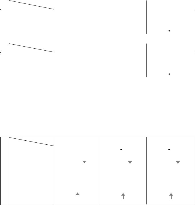
2. Memory IC replacement procedure
|
Procedure |
Screen display |
|
|
|
|
|
|
(1) |
Power off |
|
|
Switch off the power and disconnect the power cord from the outlet. |
|
|
|
|
(2) |
Replace the memory IC |
|
|
Initial value must be entered into the new IC. |
|
|
|
|
(3) |
Power on |
|
|
Connect the power cord to the outlet and switch on the power. |
|
(4)System constant check and setting
1) Press SLEEP TIMER key and, while the indication of “SLEEP TIMER
|
0 MIN.” is being displayed, press DISPLAY key and VIDEO STATUS |
SERVICE MENU |
|
|
|
|
key on the remote control unit simultaneously. |
PICTURE |
|
SOUND |
|
|
2) The SERVICE MENU screen of Fig.1 is displayed. |
|
|
||
|
THEATER |
|
OTHERS |
|
|
|
3) While the SERVICE MENU is displayed, again simultaneously press |
LOW LIGHT |
HIGH LIGHT |
|
|
|
the DISPLAY and VIDEO STATUS keys to display the Fig.2 SYSTEM |
|
|||
|
RF AFC |
|
|
|
|
|
CONSTANT screen. |
|
|
|
|
|
VCO(CW) |
|
I2C BUS CTRL |
|
|
|
4) Refer to the SYSTEM CONSTANT table and check the setting items. |
|
|
||
|
SELECT |
BY |
|
|
|
|
Where these differ, select the setting item with the MENU UP/DOWN |
EXIT BY |
EX |
||
|
OPERATE |
BY |
|||
|
key and adjust the setting with the MENU LEFT/RIGHT keys. (The |
IT |
|||
|
|
|
|
|
|
|
letters of the selected item are displayed in yellow.) |
|
[AV-32230] |
|
|
|
5) After adjusting, release the MENU LEFT/RIGHT key to store the |
|
|
||
|
|
|
|
|
|
|
setting value. |
|
|
|
|
|
6) Press the EXIT key twice to return the normal screen. |
SERVICE MENU |
|
|
|
|
|
|
|
||
|
|
PICTURE |
|
SOUND |
|
|
|
THEATER |
|
OTHERS |
|
|
|
PIP |
|
|
|
|
|
LOW LIGHT |
HIGH LIGHT |
|
|
(5) Receive channel setting |
RF AFC1 |
|
RF AFC2 |
|
|
VCO(CW) |
|
I2C BUS CTRL |
|
||
|
Refer to the OPERATING INSTRUCTIONS(USER'S GUIDE) and set the |
|
|
||
|
SELECT |
BY |
|
|
|
|
receive channels (Channels Preset) as described. |
EXIT BY |
EX |
||
|
OPERATE |
BY |
|||
|
|
IT |
|||
|
|
|
[AV-32260] |
|
|
(6) |
User settings |
|
|
Fig.1 |
|
|
|
|
|
|
|
Check the user setting items according to Table 2. |
|
|
|
|
|
|
|
|
Where these do not agree, refer to the OPERATING INSTRUCTIONS (US- |
|
|
|
|
|
|
|
|
|
|
|
|
|
|
|
|
|
ER'S GUIDE) and set the items as described. |
|
|
|
|
|
|
|
|
|
|
SYSTEM CONSTANT |
|
|
|
|||
|
|
|
|
|
|
|||
|
|
|
|
|
|
|
|
|
|
|
|
MODEL |
|
: |
99–99999 |
|
|
|
|
|
PURITY |
|
: |
NO |
|
|
|
|
|
|
|||||
(7) SERVICE MENU setting |
|
|
CCD |
|
: |
YES |
|
|
|
|
V-CHIP |
|
: |
YES |
|
|
|
Verify what to set in the SERVICE MENU, and set whatever is |
|
|
|
|
|
|||
|
|
CAN V-CHIP |
: |
YES |
|
|
||
necessary.(Fig.1) Refer to the SERVICE ADJUSTMENT for setting. |
|
|
999999999 999 |
|
|
|
||
|
|
|
|
|
|
|
|
|
|
|
|
SELECT |
BY |
|
EXIT BY |
EX |
|
|
|
|
OPERATE |
BY |
|
|
||
|
|
|
|
IT |
|
|||
|
|
|
|
|
|
|
|
|
|
|
|
|
|
|
|
|
|
|
|
|
|
|
Fig.2 |
|
|
|
No. 51802 |
11 |
Loading...