


 Loading...
JVC AV-32D104/AMA, AV-32D104/ARA, AV-32D104/AYA, AV-32D304/AMA, AV-32D304/ARA Service Manual
...SERVICE MANUAL
COLOR TELEVISION
AV-32D104/AYA, AV-32D104/ARA,
AV-32D104/AMA, AV-32D304/AYA,
AV-32D304/ARA, AV-32D304/AMA
BASIC CHASSIS
GE3
AV-32D104 AV-32D304 [RM-C1255G] [RM-C1253G]
TABLE OF CONTENTS
1 PRECAUTION. . . . . . . . . . . . . . . . . . . . . . . . . . . . . . . . . . . . . . . . . . . . . . . . . . . . . . . . . . . . . . . . . . . . . . . . . 1-3 2 SPECIFIC SERVICE INSTRUCTIONS . . . . . . . . . . . . . . . . . . . . . . . . . . . . . . . . . . . . . . . . . . . . . . . . . . . . . . 1-4 3 DISASSEMBLY . . . . . . . . . . . . . . . . . . . . . . . . . . . . . . . . . . . . . . . . . . . . . . . . . . . . . . . . . . . . . . . . . . . . . . . 1-9 4 ADJUSTMENT . . . . . . . . . . . . . . . . . . . . . . . . . . . . . . . . . . . . . . . . . . . . . . . . . . . . . . . . . . . . . . . . . . . . . . . 1-15 5 TROUBLE SHOOTING. . . . . . . . . . . . . . . . . . . . . . . . . . . . . . . . . . . . . . . . . . . . . . . . . . . . . . . . . . . . . . . . . 1-35
COPYRIGHT © 2003 VICTOR COMPANY OF JAPAN, LIMITED
No.52121
2003/5
SPECIFICATION
Items |
Contents |
|||
|
|
|
||
AV-32D104 |
|
AV-32D304 |
||
|
|
|
||
|
|
|
|
|
Dimensions (W × H × D) |
|
85.9 cm × 68.4 cm × 54.8 cm (33-7/8" × |
27" × 21-5/8") |
|
|
|
|
|
|
Mass |
|
52.0kg (114.4Ibs) |
|
|
|
|
|
|
|
TV RF System |
|
CCIR(M) |
|
|
|
|
|
|
|
Color System |
|
NTSC |
|
|
|
|
|
|
|
Sound System |
|
BTSC (Multi Channel Sound) |
|
|
|
|
|
|
|
TV Receiving Channels |
VHF LOW |
02ch~06ch : 54MHz~88MHz |
|
|
and Frequency |
|
|
|
|
VHF HIGH |
07ch~13ch : 174MHz~216MHz |
|
|
|
|
|
|
||
|
|
|
|
|
|
UHF |
14ch~69ch : 470MHz~806MHz |
|
|
|
|
|
|
|
|
CATV |
54MHz~804MHz |
|
|
|
|
Low Band : 02~06, A-8 by 02~06&01 |
|
|
|
|
High Band : 07~13 by 07~13 |
|
|
|
|
Mid Band : A~I by 14~22 |
|
|
|
|
Super Band : J~W by 23~36 |
|
|
|
|
Hyper Band : W+1~W+28 by 37~64 |
|
|
|
|
Ultra Band : W+29~W+84 by 65~125 |
|
|
|
|
Sub Mid Band : A8, A4~A1 by 01, 96~99 |
||
TV / CATV Total Channel |
180 Channels |
|
|
|
|
|
|
|
|
Intermediate Frequency |
Video IF Carrier |
45.75 MHz |
|
|
|
|
|
|
|
|
Sound IF Carrier |
41.25 MHz (4.5MHz) |
|
|
|
|
|
|
|
Color Sub Carrier |
|
3.58 MHz |
|
|
|
|
|
|
|
Power Input |
|
AC120V , 60Hz |
|
|
|
|
|
|
|
Power Consumption |
|
128W |
|
|
|
|
|
||
Picture Tube |
|
Full square Visible size:80cm (32") measured diagonally, (W65.6 cm × H49.6 cm) |
||
|
|
|
|
|
High Voltage |
|
31kV ±1.3kV (at zero beam current) |
|
|
|
|
|
||
Speaker |
|
5cm × 12cm (2" × 4-3/4"), Oval type × 2 |
||
|
|
|
|
|
Audio Power Output |
|
5W + 5W |
|
|
|
|
|||
Antenna Terminal (VHF / UHF) |
75 Ω unbalanced coaxial, F-type connector |
|||
|
|
|
|
|
INPUT1 (Rear) |
VIDEO |
1V(p-p), negative sync, 75 Ω , RCA pin jack × 1 |
||
|
|
|
|
|
|
S-VIDEO |
Mini DIN 4-pin × 1 |
|
|
|
|
Y : 1V(p-p), negative sync, 75 Ω |
|
|
|
|
C : 0.286V(p-p), (burst signal), 75 Ω |
|
|
|
|
|
||
|
AUDIO (L/MONO, R) |
500mVrms(-4dBs), high impedance, RCA pin jack × 2 |
||
|
|
|
|
|
INPUT2 (Rear) |
VIDEO |
--------- |
|
1V(p-p), negative sync, 75 Ω , RCA pin |
|
|
|
|
jack × 1 |
|
COMPONENT VIDEO |
Y&Video : 1V(p-p), negative sync, 75 Ω |
, |
Y : 1V(p-p), negative sync, 75 Ω , |
|
|
RCA pin jack × 1 |
|
RCA pin jack × 1 |
|
|
Pb/Pr : 0.7V(p-p), 75 Ω , RCA pin jack × |
2 |
Pb/Pr : 0.7V(p-p), 75 Ω , RCA pin jack × 2 |
|
|
|
|
|
|
AUDIO (L / MONO, R) |
500mVrms(-4dBs), high impedance, RCA pin jack × 2 |
||
|
|
|
||
INPUT3 (Front) |
VIDEO |
1V(p-p), negative sync, 75 Ω , RCA pin jack × 1 |
||
|
|
|
||
|
AUDIO (L / MONO, R) |
500mV(rms)(-4dBs), high impedance, RCA pin jack × 2 |
||
|
|
|
|
|
AUDIO OUTPUT (L / R) |
|
500mV(rms)(-4dBs)low Impedance, (400kHz when modulated 100%) , |
||
|
|
RCA pin jack × 2 |
|
|
AV COMPULINK lll |
|
--------- |
|
3.5mm mini jack × 1 |
|
|
|
|
|
Remote Control Unit |
|
RM-C1255G (AA/R6/UM-3 battery × 2) |
|
RM-C1253G (AA/R6/UM-3 battery × 2) |
|
|
|
|
|
Design & specifications are subject to change without notice.
1-2 (No.52121)
SECTION 1 PRECAUTION
1.1SAFETY PRECAUTIONS
(1)The design of this product contains special hardware, many circuits and components specially for safety purposes. For continued protection, no changes should be made to the original design unless authorized in writing by the manufacturer. Replacement parts must be identical to those used in the original circuits. Service should be performed by qualified personnel only.
(2)Alterations of the design or circuitry of the products should not be made. Any design alterations or additions will void the manufacturer's warranty and will further relieve the manufacturer of responsibility for personal injury or property damage resulting therefrom.
(3)Many electrical and mechanical parts in the products have special safety-related characteristics. These characteristics are often not evident from visual inspection nor can the protection afforded by them necessarily be obtained by using replacement components rated for higher voltage, wattage, etc. Replacement parts which have these special safety characteristics are identified in the parts list of Service manual. Electrical components having such features are identified by shading on the schematics and by (  ) on the parts list in Service manual. The use of a substitute replacement which does not have the same safety characteristics as the recommended replacement part shown in the parts list of Service manual may cause shock, fire, or other hazards.
(4)Use isolation transformer when hot chassis.
The chassis and any sub-chassis contained in some products are connected to one side of the AC power line. An isolation transformer of adequate capacity should be inserted between the product and the AC power supply point while performing any service on some products when the HOT chassis is exposed.
(5)Don't short between the LIVE side ground and ISOLATED (NEUTRAL) side ground or EARTH side ground when repairing.
Some model's power circuit is partly different in the GND. The difference of the GND is shown by the LIVE : (  ) side GND, the ISOLATED (NEUTRAL) : (
  ) side GND and EARTH : (
  ) side GND.
Don't short between the LIVE side GND and ISOLATED (NEUTRAL) side GND or EARTH side GND and never measure the LIVE side GND and ISOLATED (NEUTRAL) side GND or EARTH side GND at the same time with a measuring apparatus (oscilloscope etc.). If above note will not be kept, a fuse or any parts will be broken.
(6)If any repair has been made to the chassis, it is recommended that the B1 setting should be checked or adjusted (See ADJUSTMENT OF B1 POWER SUPPLY).
(7)The high voltage applied to the picture tube must conform with that specified in Service manual. Excessive high voltage can cause an increase in X-Ray emission, arcing and possible component damage, therefore operation under excessive high voltage conditions should be kept to a minimum, or should be prevented. If severe arcing occurs, remove the AC power immediately and determine the cause by visual inspection (incorrect installation, cracked or melted high voltage harness, poor soldering, etc.). To maintain the proper minimum level of soft X-Ray emission, components in the high voltage circuitry including the picture tube must be the exact replacements or alternatives approved by the manufacturer of the complete product.
(8)Do not check high voltage by drawing an arc. Use a high voltage meter or a high voltage probe with a VTVM. Discharge the picture tube before attempting meter connection, by connecting a clip lead
to the ground frame and connecting the other end of the lead through a 10kΩ 2W resistor to the anode button.
(9)When service is required, observe the original lead dress. Extra precaution should be given to assure correct lead dress in the high voltage circuit area. Where a short circuit has occurred, those components that indicate evidence of overheating should be replaced. Always use the manufacturer's replacement components.
(10)Isolation Check (Safety for Electrical Shock Hazard)
After re-assembling the product, always perform an isolation check on the exposed metal parts of the cabinet (antenna terminals, video/audio input and output terminals, Control knobs, metal cabinet, screw heads, earphone jack, control shafts, etc.) to be sure the product is safe to operate without danger of electrical shock.
a)Dielectric Strength Test
The isolation between the AC primary circuit and all metal parts exposed to the user, particularly any exposed metal part having a return path to the chassis should withstand a voltage of 3000V AC (r.m.s.) for a period of one second. (. . . . Withstand a voltage of 1100V AC (r.m.s.) to an appliance rated up to 120V, and 3000V AC (r.m.s.) to an appliance rated 200V or more, for a period of one second.)
This method of test requires a test equipment not generally found in the service trade.
b)Leakage Current Check
Plug the AC line cord directly into the AC outlet (do not use a line isolation transformer during this check.). Using a "Leakage Current Tester", measure the leakage current from each exposed metal part of the cabinet, particularly any exposed metal part having a return path to the chassis, to a known good earth ground (water pipe, etc.). Any leakage current must not exceed 0.5mA AC (r.m.s.).
However, in tropical area, this must not exceed 0.2mA AC (r.m.s.).
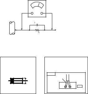
Alternate Check Method
Plug the AC line cord directly into the AC outlet (do not use a line isolation transformer during this check.). Use an AC voltmeter having 1000Ω per volt or more sensitivity in the following manner. Connect a 1500Ω 10W resistor paralleled by a 0.15µF AC-type capacitor between an exposed metal part and a known good earth ground (water pipe, etc.). Measure the AC voltage across the resistor with the AC voltmeter. Move the resistor connection to each exposed metal part, particularly any exposed metal part having a return path to the chassis, and measure the AC voltage across the resistor. Now, reverse the plug in the AC outlet and repeat each measurement. Any voltage measured must not exceed 0.75V AC (r.m.s.). This corresponds to 0.5mA AC (r.m.s.).
However, in tropical area, this must not exceed 0.3V AC (r.m.s.). This corresponds to 0.2mA AC (r.m.s.).
AC VOLTMETER (HAVING 1000 /V,
/V,
OR MORE SENSITIVITY)
0.15 F AC-TYPE |
|
||
|
|
PLACE THIS PROBE |
|
1500 |
10W |
ON EACH EXPOSED |
|
METAL PART |
|||
|
|
||
GOOD EARTH GROUND
(11)High voltage hold down circuit check.
After repair of the high voltage hold down circuit, this circuit shall be checked to operate correctly.See item "How to check the high voltage hold down circuit".
This mark shows a fast operating fuse, the letters indicated below show the rating.
 A
A 
 V
V
POWER CORD REPLACEMENT WARNING.
Connecting the white line side of power cord to "WHT" character side.
PWB |
White line side |
PW |
WHT |
(No.52121)1-3

SECTION 2
SPECIFIC SERVICE INSTRUCTIONS
2.1FEATURES
•Title CLOSED CAPTION broadcast of C1~C4 and T1~T4 formula is receivable.
•The voice multiplex function of the MTS system is built in.
•By the 3-line digital comb filter, the refreshed image can be seen.
•Expression of a favorite screen can be chosen by the VIDEO STATUS function.
•A program can be enjoyed with a powerful sound by the HYPER SURROUND function.
•Since the V-chip is built in, it can choose, view and listen to a healthy program.
•The RETURN + function is built-in.
•A quick favorite program can be looked for by the HYPER-SCAN function.
•Since the component signal input terminal is equipped, it reappears direct without deteriorating the signal from DVD.
•By the THEATER PRO function, a reality to which it is viewing and listening in the movie theater can be tasted. (AV-32D304 only)
•By the COMPULINK III function, operation interlocked with the DVD deck can be performed from remote control. (AV-32D304 only)
2.2HOW TO IDENTIFY MODELS
How to recognize from the appearance of the model concerned is written below.
Please distinguish from several contents currently printed on the rating label.
MODEL NAME
AV-32D104 or AV-32D304
***********
DISTINGUISH NAME
AYA , ARA or AMA
1-4 (No.52121)
2.3MAIN DIFFERENCE LIST
Item |
AV-32D104/AYA |
AV-32D104/ARA |
AV-32D104/AMA |
AV-32D304/AYA |
AV-32D304/ARA |
AV-32D304/AMA |
|
|
|
|
|
|
|
THEATER PRO BUTTON |
|
NON |
|
|
YES |
|
|
|
|
|
|
|
|
WHITE BLANCE |
|
NON |
|
|
YES |
|
(COLOR TEMP.) |
|
|
|
|
|
|
GAME BUTTON |
|
YES |
|
|
NON |
|
|
|
|
|
|
|
|
BBE SYSTEM |
|
NON |
|
|
YES |
|
|
|
|
|
|
||
VIDEO-IN |
NON (comnon use to Component-Y) |
|
YES |
|
||
(INPUT-2:REAR-TERMINAL) |
|
|
|
|
|
|
|
|
|
|
|
|
|
AV COMPULINK lll |
|
NON |
|
|
YES |
|
|
|
|
|
|
|
|
REMOTE CONTROL UNIT |
|
RM-C1255G |
|
|
RM-C1253G |
|
|
|
|
|
|
|
|
ILLUMINATION |
|
NON |
|
|
YES |
|
(REMOTE CONTROL UNIT) |
|
|
|
|
|
|
|
|
|
|
|
|
|
MAIN PWB ASS'Y |
SGE-1505A-M2 |
SGE-1509A-M2 |
SGE-1501A-M2 |
SGE-1507A-M2 |
SGE-1511A-M2 |
SGE-1503A-M2 |
|
|
|
|
|
|
|
CRT SOCKET PWB ASS'Y |
SGE-3503A-M2 |
SGE-3505A-M2 |
SGE-3501A-M2 |
SGE-3503A-M2 |
SGE-3505A-M2 |
SGE-3501A-M2 |
|
|
|
|
|
|
|
AV SELECT PWB ASS'Y |
SGE-5501A-M2 |
← |
← |
SGE-5502A-M2 |
← |
← |
|
|
|
|
|
|
|
FRONT CABINET ASS'Y |
LC10641-006A-A |
← |
← |
LC10641-005C-A |
← |
← |
|
|
|
|
|
|
|
TERMINAL BOARD |
LC20899-006A-A |
← |
← |
LC20899-004A-A |
← |
← |
|
|
|
|
|
|
|
PICTURE TUBE (ITC) |
A80AKB50X04 |
A80AEJ15X01 |
A80JUA061X06 |
A80AKB50X04 |
A80AEJ15X01 |
A80JUA061X15 |
|
|
|
|
|
|
|
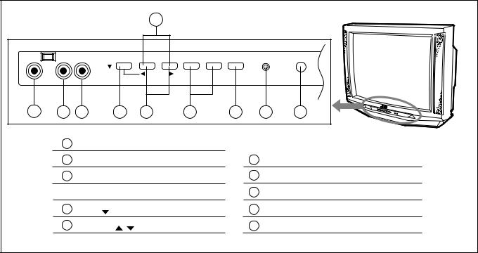
2.4FUNCTIONS
FRONT PANEL CONTROLS
|
|
|
|
|
6 |
|
|
|
|
|
|
|
|
|
MENU |
- CHANNEL + |
- VOLUME + |
POWER |
ON TIMER |
|
|
INPUT3 |
|
|
|
|
|
|
|
|
|
|
|
|
|
|
|
OPERATE |
|
|
|
|
|
VIDEO |
L/MONO-AUDIO-R |
|
|
|
|
|
|
|
|
|
1 |
2 |
3 |
|
4 |
5 |
7 |
8 |
|
9 |
10 |
|
1 |
INPUT 3 : VIDEO |
|
|
|
|
|
|
||
|
2 |
INPUT 3 : AUDIO L/MONO |
|
|
6 |
CHANNEL (-/+) BUTTON |
||||
|
3 |
INPUT 3 : AUDIO R |
|
|
7 |
VOLUME (-/+) BUTTON |
||||
|
|
|
|
|
|
|
||||
|
|
|
|
|
|
|
|
8 |
POWER SW BUTTON |
|
|
4 |
MENU ( |
) BUTTON |
|
|
9 |
ON TIMER / POWER INDICATOR |
|||
|
|
|
|
|
|
|
||||
|
5 |
OPERATE ( |
/ |
) BUTTON |
|
|
10 |
REMOTE CONTROL SENSOR |
||
|
|
|
|
|
|
|
||||
(No.52121)1-5
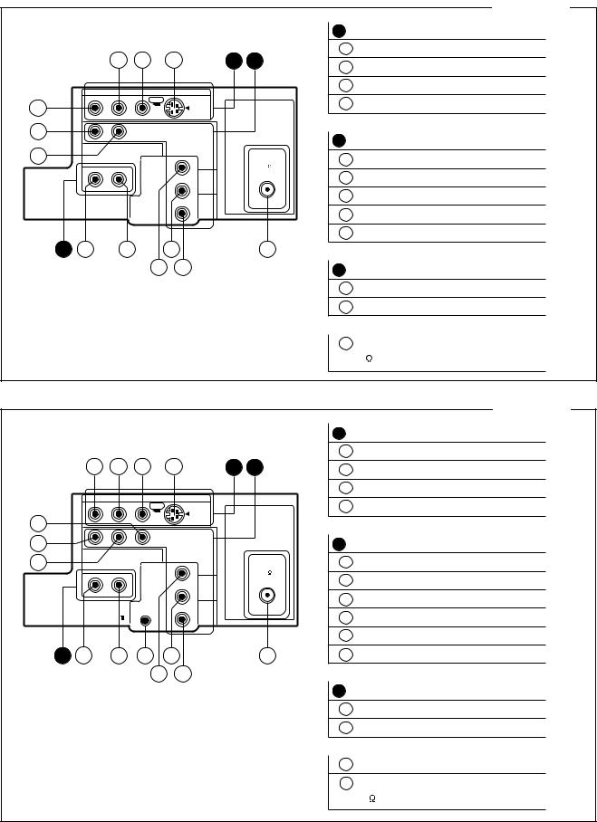
REAR TERMINAL
|
|
|
|
|
|
|
|
|
AV-32D104 |
|
|
|
|
|
|
|
A |
INPUT 1 TERMINAL |
|
|
|
|
|
|
|
|
1 |
|
S-VIDEO |
|
|
3 |
2 |
1 |
A |
B |
2 |
|
VIDEO |
|
|
|
|
|
|
|
|
||
|
AUDIO |
VIDEO |
S-VIDEO |
|
|
3 |
|
AUDIO-L/MONO |
|
|
|
|
|
|
|
||||
|
R |
L/MONO |
OVER |
|
|
|
4 |
|
AUDIO-R |
4 |
|
|
|
INPUT 1 |
|
|
|
||
|
|
|
|
|
|
|
|
|
|
7 |
|
|
|
INPUT 2 |
|
|
|
|
|
|
|
|
|
|
|
B |
|
|
|
|
|
|
|
COMPONENT |
|
|
INPUT 2 TERMINAL |
||
6 |
|
|
|
VIDEO-IN |
|
|
|
|
|
|
|
|
|
|
|
6 |
|
AUDIO-L/MONO |
|
|
|
|
|
Y |
|
75 |
|
||
|
R |
L |
|
|
|
|
|
||
|
|
VIDEO |
|
(VHF / UHF) |
|
|
|
||
|
|
|
|
|
7 |
|
AUDIO-R |
||
|
|
|
|
|
|
|
|
||
|
AUDIO OUT |
|
PB |
|
|
|
|
|
|
|
|
|
|
|
|
8 |
|
COMPONENT-Y / VIDEO-IN |
|
|
|
|
|
|
|
|
|
||
|
|
|
|
PR |
|
|
9 |
COMPONENT-PB |
|
|
|
|
|
|
|
|
|||
|
|
|
|
|
|
|
10 COMPONENT-PR |
||
C |
12 |
11 |
|
9 |
|
14 |
|
|
|
|
|
|
8 |
10 |
|
|
C AUDIO OUTPUT TERMINAL (Fixed) |
||
|
|
|
|
|
|
|
|||
|
|
|
|
|
|
|
11 |
AUDIO-L |
|
|
|
|
|
|
|
|
12 |
AUDIO-R |
|
|
|
|
|
|
|
|
14 ANTENNA TERMINAL |
||
|
|
|
|
|
|
|
|
|
758*( 7*( |
|
|
|
|
|
|
|
|
|
AV-32D304 |
|
|
|
|
|
A |
INPUT 1 TERMINAL |
|
|
|
|
|
1 |
S-VIDEO |
4 |
3 |
2 |
1 |
A B |
2 |
VIDEO |
|
|
|
|
|
3 |
AUDIO-L/MONO |
AUDIO |
VIDEO |
S-VIDEO |
|
|
|
|
R |
L/MONO |
OVER |
|
|
4 |
AUDIO-R |
|
|
|
INPUT 1 |
|
||
|
|
|
|
|
|
|
5 |
|
|
|
|
|
|
7 |
|
|
INPUT 2 |
|
|
|
|
|
|
|
B |
INPUT 2 TERMINAL |
|
6 |
|
|
COMPONENT |
|
5 |
VIDEO |
|
|
|
|
|||
R |
L |
|
Y |
75 |
|
|
|
|
(VHF / UHF) |
6 |
AUDIO-L/MONO |
||
|
|
|
|
|||
|
|
|
|
|
||
AUDIO OUT |
|
PB |
|
7 |
AUDIO-R |
|
|
|
|
|
|||
|
|
|
|
|
||
AV CONPULINK |
|
PR |
|
8 |
COMPONENT-Y |
|
|
|
|
|
|
9 COMPONENT-PB |
|
C 12 |
11 |
13 |
9 |
14 |
10 COMPONENT-PR |
|
|
|
8 |
10 |
|
|
|
C AUDIO OUTPUT TERMINAL (Fixed)
11 AUDIO-L
12 AUDIO-R
13 COMPULINK TERMINAL
14 ANTENNA TERMINAL
758*( 7*(
1-6 (No.52121)

REMOTE CONTROL UNIT
|
|
|
|
|
|
|
|
RM-C1255G [AV-32D104] |
||
|
|
|
1 |
VCR/ DVD KEY |
|
|
|
|
|
|
1 |
|
|
2 |
TV/ CATV KEY |
|
|
|
|
|
|
|
|
|
|
|
|
|
|
|||
|
|
|
3 |
INPUT KEY: |
TV VIDEO1 |
VIDO2 |
V2-COMPONENT |
VIDEO3 |
||
2 |
11 |
|
4 |
DISPLAY KEY |
|
|
|
|
|
|
|
|
|
|
|
|
|
|
|
||
|
|
|
5 |
SLEEP TIMER KEY: 0 |
15 |
30 |
165 180 |
|
|
|
3 |
|
|
6 |
HYPER SURROUND KEY |
|
|
|
|
||
4 |
12 |
|
|
Hyper Surround Can be Changed ON/OFF |
|
|
||||
5 |
|
|
7 |
VIDEO STATUS KEY: STANDARD DYNAMIC THEATER |
GAME |
|||||
6 |
|
|
8 |
MUTING KEY |
|
|
|
|
|
|
7 |
18 |
|
9 |
VOLUME (+/-) KEY / VOL. ( |
/ |
) KEY |
|
|
||
|
|
|
|
|
||||||
19 |
13 |
|
10 |
MENU KEY: |
PICTURE ADJUST SOUND ADJUST |
|
|
|||
|
|
|
|
|
INITIAL SETUP |
CLOCK/TIMERS |
|
|
||
8 |
14 |
|
11 |
POWER KEY |
|
|
|
|
|
|
|
|
15 |
|
|
|
|
|
|
||
|
|
|
|
|
|
|
|
|
|
|
9 |
|
|
12 |
CHANNEL NUMBER KEY |
|
|
|
|
||
10 |
16 |
|
13 |
GAME KEY |
|
|
|
|
|
|
|
|
|
14 |
C.C. (CLOSED CAPTION) KEY: |
OFF |
CAPTION TEXT |
|
|
||
|
17 |
|
15 |
CHANNEL (+/-) KEY / CH. ( |
/ |
) KEY |
|
|
||
|
|
|
|
|
||||||
|
|
|
16 |
EXIT KEY |
|
|
|
|
|
|
|
|
|
17 |
VCR CONTROL KEY |
|
|
|
|
|
|
|
|
|
18 |
RETURN + KEY |
|
|
|
|
|
|
|
|
|
19 |
100+KEY |
|
|
|
|
|
|
|
|
|
|
|
|
|
|
RM-C1253G [AV-32D304] |
||
1
2
3
4
5
6
7
8
9
10
11
12
13
20
19
14
15
17
18
1VCR/ DVD KEY
2TV/ CATV KEY
3 INPUT KEY:  TV VIDEO1
 VIDO2
VIDO2 V2-COMPONENT
 VIDEO3
4DISPLAY KEY
5SLEEP TIMER KEY:  0
0 15
15 30
30 
 165
165 180
180 
6SOUND KEY
HYPER SORRUND and BBE Can be Changed ON/OFF
7VIDEO STATUS KEY:  STANDARD
  DYNAMIC
 THEATER
 GAME
GAME 
8THEATER PRO KEY
9MUTING KEY
10 VOLUME +/- KEY / VOL. ( /
/  ) KEY
) KEY
16 |
11 |
MENU KEY |
PICTURE ADJUST |
|
|
SOUND ADJUST |
|
|||
|
INITIAL SETUP |
|
|
CLOCK/TIMERS |
|
|
||||
|
|
|
|
|
|
|
||||
12POWER KEY
13CHANNEL NUMBER KEY
14LIGHT KEY
15C.C. (CLOSED CAPTION) KEY:  OFF
OFF CAPTION
 TEXT
TEXT
16CHANNEL (+/-)KEY / CH. ( /
/ ) KEY
) KEY
17EXIT KEY
18VCR CONTROL KEY
19RETURN + KEY
20100+KEY
(No.52121)1-7
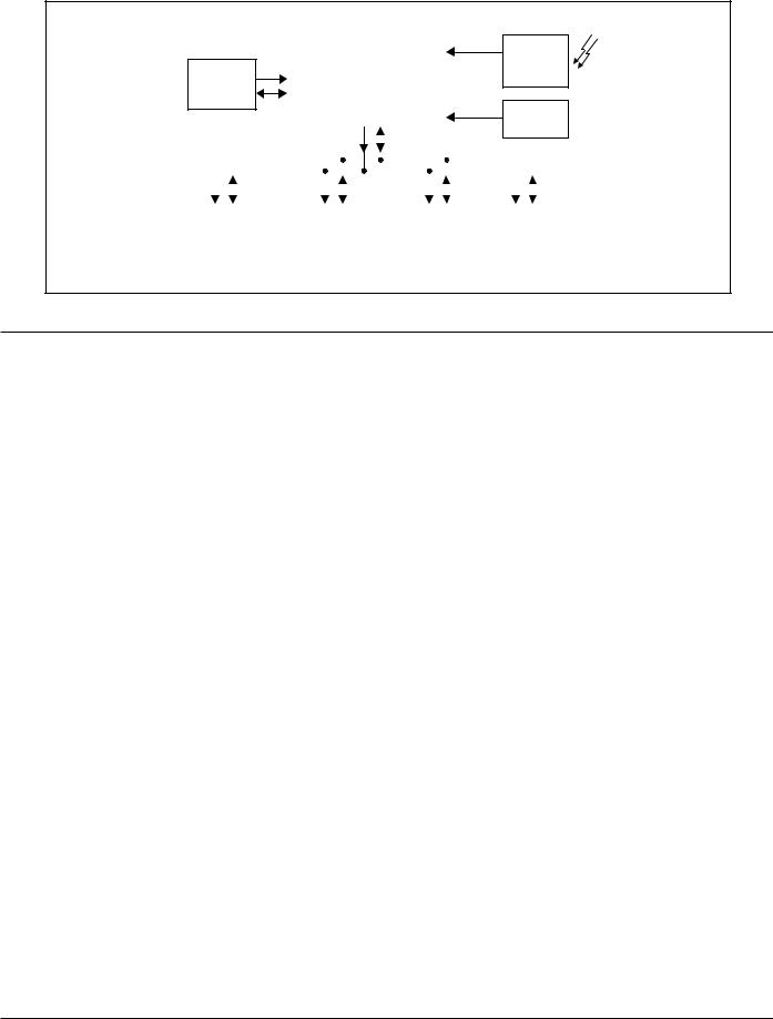
2.5SYSTEM BLOCK DIAGRAM
IC702
MEMORY
S C L 1 |
S D A 1 |
MAIN MI-COM |
REMOCON |
|
|
IC201 |
|
(MICOM/V/C/DEF) |
A F T 1 |
|
|
|
|
SCL0 |
SDA0 |
|
|
IC7701
REMOCON RECEIVER
IC101
IF DET
|
|
|
|
|
|
|
|
|
|
|
|
|
|
|
|
|
|
|
|
S C L 0 |
|
|
|
S D A 0 |
S C L 0 |
|
|
|
S D A 0 |
S C L 0 |
|
|
|
S D A 0 |
S C L 0 |
|
|
|
S D A 0 |
|
|
|
|
|
|
|
|
IC501 |
|
IC5501 |
|
TU001 |
|
IC5201 |
MTS |
|
AV SW |
|
TUNER |
|
3L Y/C |
|
|
|
|
|
|
|
2.6MAIN MI-COM (CPU) PIN FUNCTION
Pin |
Pin name |
I/O |
Function |
|
No. |
||||
|
|
|
||
|
|
|
|
|
|
|
|
|
|
1 |
LED/ADC8Bit |
I |
AFT control2 |
|
|
|
|
|
|
2 |
ADC8bit |
I |
AFT control1 |
|
|
|
|
|
|
3 |
ADC8bit/TC1/Int2 |
I |
Key IN |
|
|
|
|
|
|
4 |
uPLDVss |
- |
GND |
|
|
|
|
|
|
5 |
Reset |
I |
RESET,RESET:[L] |
|
|
|
|
|
|
6 |
Xout |
O |
8MHz OSC |
|
|
|
|
|
|
7 |
Xin |
I |
8MHz OSC |
|
|
|
|
|
|
8 |
TEST |
- |
GND |
|
|
|
|
|
|
9 |
uP DVdd |
- |
5V |
|
|
|
|
|
|
10 |
AGC_MUTE |
O |
AGC_MUTE,MUTING:[L],NORMALY:[H] |
|
11 |
UP VVss |
- |
GND |
|
|
|
|
|
|
12 |
TV HGND |
- |
GND |
|
|
|
|
|
|
13 |
FBP in |
I |
FBP |
|
|
|
|
|
|
14 |
Hout |
O |
H OUT |
|
|
|
|
|
|
15 |
HVcc |
- |
9V |
|
16 |
HAFC 1 |
- |
H AFC |
|
|
|
|
|
|
17 |
Vsaw |
- |
GND |
|
|
|
|
|
|
18 |
Vout |
O |
V OUT |
|
|
|
|
|
|
19 |
EW out |
O |
EW OUT |
|
|
|
|
|
|
20 |
Xray |
I |
X RAY |
|
21 |
Ys |
I |
YS |
|
22 |
Cb in |
I |
Cb INPUT |
|
23 |
Y in |
I |
Y INPUT |
|
24 |
Cr in |
I |
Cr INPUT |
|
25 |
TV DVcc |
- |
3.3V |
|
26 |
V3in/Cin |
I |
V3 IN |
|
27 |
EHTin |
I |
EHT IN |
|
28 |
V2in/Yin |
I |
V2 IN |
Pin |
Pin name |
I/O |
Function |
||
No. |
|||||
|
|
|
|
||
|
|
|
|
||
|
|
|
|
||
29 |
TV DGND |
I |
GND |
||
|
|
|
|
|
|
30 |
V1in |
|
I |
V1 IN |
|
|
|
|
|
|
|
31 |
ABCL |
|
O |
ABCL IN |
|
|
|
|
|
||
32 |
Moni OUT |
- |
MONITOR |
||
|
|
|
|
||
33 |
Black Det |
O |
BLACK DETECTION |
||
|
|
|
|
|
|
34 |
SVMout |
|
- |
SVM OUT |
|
|
|
|
|
||
35 |
APL DET |
- |
APL FILTER |
||
|
|
|
|
||
36 |
Chroma PLL |
O |
APL FILTER |
||
|
|
|
|
|
|
37 |
fsc out |
|
- |
3.58MHz |
|
|
|
|
|
||
38 |
TV YC Vcc |
O |
5V |
||
|
|
|
|
|
|
39 |
R out |
|
O |
R OUT |
|
|
|
|
|
|
|
40 |
G out |
|
O |
G OUT |
|
|
|
|
|
|
|
41 |
B out |
|
- |
B OUT |
|
|
|
|
|
||
42 |
RGB Vcc |
I |
9V |
||
|
|
|
|
|
|
43 |
IK in |
|
- |
IK INPUT |
|
44 |
TV AGND |
- |
GND |
||
|
|
|
|
||
45 |
uP AGND |
- |
GND |
||
|
|
|
|
||
46 |
uP Avdd |
O |
5V |
||
|
|
|
|
||
47 |
MAIN-POWER |
O |
MAIN POWER:ON:[L],OFF[H] |
||
|
|
|
|
||
48 |
HAZARD |
I |
SELFCHECK:HAZARD:[H],NORMALY:[L] |
||
|
|
|
|
|
|
49 |
SDA |
SDAO |
I/O |
SCA0 |
|
|
|
|
|
|
|
50 |
SDA |
SDAO |
O |
SCL0 |
|
|
|
|
|
||
51 |
PWM7Bit/TC2/Int0 |
I/O |
SDA1(EEPROM) |
||
|
|
|
|
||
52 |
PWM14bit |
O |
AGC ADJUST |
||
|
|
|
|
||
53 |
Int5/Stop |
O |
SCL1(EEPROM) |
||
|
|
|
|
||
54 |
Int4/TC3 |
O |
LED,ON:[L],OFF:[H] |
||
|
|
|
|
||
55 |
Int3/RXIN |
I |
REMOCON INPUT |
||
|
|
|
|
||
56 |
LED2/CSOUT |
I |
COMPULINK |
||
|
|
|
|
|
|
1-8 (No.52121)
SECTION 3
DISASSEMBLY
3.1DISASSEMBLY PROCEDURE
3.1.1 REMOVING THE REAR COVER
•Unplug the power plug.
(1)As shown in Fig.2, take out the 14 screws [A].
(2)Remove the REAR COVER toward you.
NOTE :
When reinstalling the REAR COVER, carefully push it inward after inserting the chassis into the REAR COVER groove.
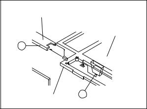
3.1.2 REMOVING THE CHASSIS BASE
•Remove the REAR COVER.
(1)Slightly raise the both sides of the CHASSIS BASE by hand, and teka out the 2 claws [B] (Fig.1 and Fig.2) under the both sides of the chassis from the chassis rail.
(2)As shown in Fig.1, draw the CHASSIS BASE backward along the chassis rail [C] (Fig.1) in the arrow direction [D] (Fig.2).
(If necessary, detach the wire clamp, connector's etc.)
NOTE :
When conducting a check with power supplied, be sure to confirm that the CRT earth wire is connected to the CRT SOCKET PWB and the MAIN PWB.
3.1.3REMOVING THE TERMINAL BOARD
• Remove the REAR COVER.
(1) As shown in Fig.2, take out the 4 screws [E].
(2) When you pull out the TERMINAL BOARD, it can be removed.
3.1.4REMOVING THE FRONT CONTROL PW BOARD
•Remove the REAR COVER.
•Remove the CHASSIS BASE.
(1)As shown in Fig.2, take out the 3 screws [F] attached the FRONT CONTROL PWB with the front cabinet.
(2)Then remove the FRONT CONTROL PWB.
3.1.5 REMOVING THE FRONT TERMINAL PW BOARD
•Remove the REAR COVER.
•Remove the CHASSIS BASE.
(1)As shown in Fig.2, take out the 2 screws [G].
(2)Then remove the FRONT TERMINAL PWB.
3.1.6REMOVING THE SPEAKER
• Remove the REAR COVER.
• Remove the CHASSIS BASE.
(1) As shown in Fig.2, take out the 4 screws [H].
(2) Follow the same steps when removing the other hand SPEAKER.
3.1.7CHECKING THE MAIN PW BOARD
•To check the backside of the MAIN PWB.
(1)Pull out the CHASSIS BASE. (Refer to REMOVING THE CHASSIS BASE).
(2)Erect the chassis vertically so that you can easily check from the backside of the MAIN PWB.
CAUTION :
•When erecting the chassis, be careful so that there will be no contacting with other PWB.
•Before turning on power, make sure that the CRT earth wire and other connectors are properly connected.
3.1.8 WIRE CLAMPING AND CABLE TYING
(1)Be sure to clamp the wire.
(2)Never remove the cable tie used for tying the wires together.
Should it be inadvertently removed, be sure to tie the wires with a new cable tie.
FRONT CABINET
|
MAIN PWB |
C |
|
CHASSIS BASE |
B |
Fig.1 |
|
(No.52121)1-9

FRONT CABINET
CRT
SPEAKER


 H
H
POWER CORD
CRT SOCKET PWB
FRONT TERMINAL PWB
CLAW B
MAIN PWB
HTV
G
CHASSIS BASE

 H
H
FRONT
CONTROL F
PWB
SPEAKER
CLAW B |
D |
|
AV SEL PWB |
E |
|
TERMINAL BOARD |
REAR COVER |
|
NOTE
This illustration describes about AV-32D304. Although the AV-32D104 is slightly different from this illustration, it can
use for AV-32D104 in the same steps as this illustration.
A
Fig.2
1-10 (No.52121)
3.2REMOVING THE CRT
NOTE:
•Replacement of the CRT should be performed by 2 or more persons.
•After removing the REAR COVER, CHASSIS etc.,
(1)Putting the CRT change table on soft cloth, the CRT change table should also be covered with such soft cloth (shown in Fig. 3).
(2)While keeping the surface of CRT down, mount the TV set on the CRT change table balanced will as shown in Fig. 3.
(3)Remove 4 screws marked by arrows with a box type screwdriver as shown in Fig. 4.
NOTE:
Since the cabinet will drop when screws have been removed, be sure to support the cabinet with hands.
(4)After 4 screws have been removed, put the cabinet slowly on cloth (At this time, be carefully so as not to damage the front
surface of the cabinet) shown in Fig. 5.
NOTE:
•The CRT should be assembled according to the opposite sequence of its dismounting steps.
•The CRT change table should preferably be smaller that the CRT surface, and its height be about 35cm.
CRT CHANGE TABLE
APPROX.
35cm
CLOTH 
Fig.3
CRT
CRT CHANGE TABLE
BOX
TYPE SCREW DRIVER
Fig.4
CRT
CABINET |
CRT |
|
CHANGE TABLE |
||
|
Fig.5
(No.52121)1-11
Loading...